

Frigidaire FFED3015PBA, FFED3015PBB, FFED3015PBC, FFED3015PBD, FFED3015PBE Installation Guide
...Page 1
iNSTALLATiON iNSTRUCTiONS
30" ELECTRIC DROP-IN RANGE
iNSTALLATiON AND SERVICE MUST BE PERFORMED BY A QUALiFiED iNSTALLER.
iMPORTANT: SAVE FOR LOCAL ELECTRICAL iNSPECTOR'S USE.
READ AND SAVE THESE iNSTRUCTiONS FOR FUTURE REFERENCE.
United States
FOR YOUR SAFETY: Do not store or use gasoline
or other flammable vapors and liquids in the vicinity of this or
any other appliance.
Table of Contents
Important Safety Instructions ........................................... 2
Cutout Dimensions ....................................................... 3-4
Electrical Requirements .................................................... 5
Electrical Connection .................................................... 5-6
Serial Plate Location ......................................................... 6
Range Installation ............................................................ 7
Anti-tip Bracket Installation ........................................... 8-9
Check Operation ............................................................ 10
Model and Serial Number Location ................................ 10
Before you call for Service.............................................. 10
Important Notes to the Installer
1. Read all instructions contained in these installation
instructions before installing range.
2. Remove all packing material from the oven and the
drawer compartments before connecting the electrical
supply to the range.
3. Observe all governing codes and ordinances.
4. Be sure to leave these instructions with the consumer.
Important Note to the Consumer
Keep these instructions with your owner's guide for future
reference.
Printed in Canada
P/N 318201627 (1209) Rev.B
English - pages 1-10
Espaflol- paginas 11-20
Page 2
iMPORTANT SAFETY iNSTRUCTiONS
This manual contains important safety symbols and instructions. Please pay attention to these
symbols and follow all instructions given.
• Besure your range isinstalled and grounded properly
by a qualified installer or service technician.
• This range must be electrically grounded in
accordance with local codes or, in their absence,
with the National Electrical Code ANSI/NFPA No.
70--latest edition.
• The installation of appliances designed for
manufactured (mobile) home installation must conform
with Manufactured Home Construction and Safety
Standard, title 24CFR, part 3280 [Formerly the Federal
Standard for Mobile Home Construction and Safety,
title 24, HUD (part 280)] or when such standard
is not applicable, the Standard for Manufactured
Home Installation 1982 (Manufactured Home Sites,
Communities and Setups), ANSI Z225.1/NFPA 501A-
latest edition, or with local codes.
• Make sure the wall coverings around the range
can withstand the heat generated by the range.
• Before installing the range in an area covered
with linoleum or any other synthetic floor
covering, make sure the floor covering can
withstand heat at least 90°F above room
temperature without shrinking, warping or
discoloring. Do not install the range over carpeting
unless you place an insulating pad or sheet of 1/4"
thick plywood between the range and carpeting.
Never leave children alone or
unattended in the area where an appliance is in
use. As children grow, teach them the proper, safe use
of all appliances. Never leave the oven door open when
the range is unattended.
Stepping, leaning or sitting on the
door of this range can result in serious injuries and
can also cause damage to the range.
horizontally a minimum of 5 inches beyond the bottom
of the cabinet.
Do not use the oven as a storage space. This
creates a potentially hazardous situation.
Never use your range for warming or heating the
room. Prolonged use of the range without adequate
ventilation can be dangerous.
Do not store or use gasoline or other flammable
vapors and liquids near this or any other
appliance. Explosions or fires could result.
Reset all controls to the "off" position after using
a programmable timing operation.
FOR MODELS WiTH SELF-CLEAN FEATURE:
Remove broiler pan, food and other utensils before
self-cleaning the oven. Wipe up excessspillage. Follow
the pre cleaning instructions inthe Use and Care Guide.
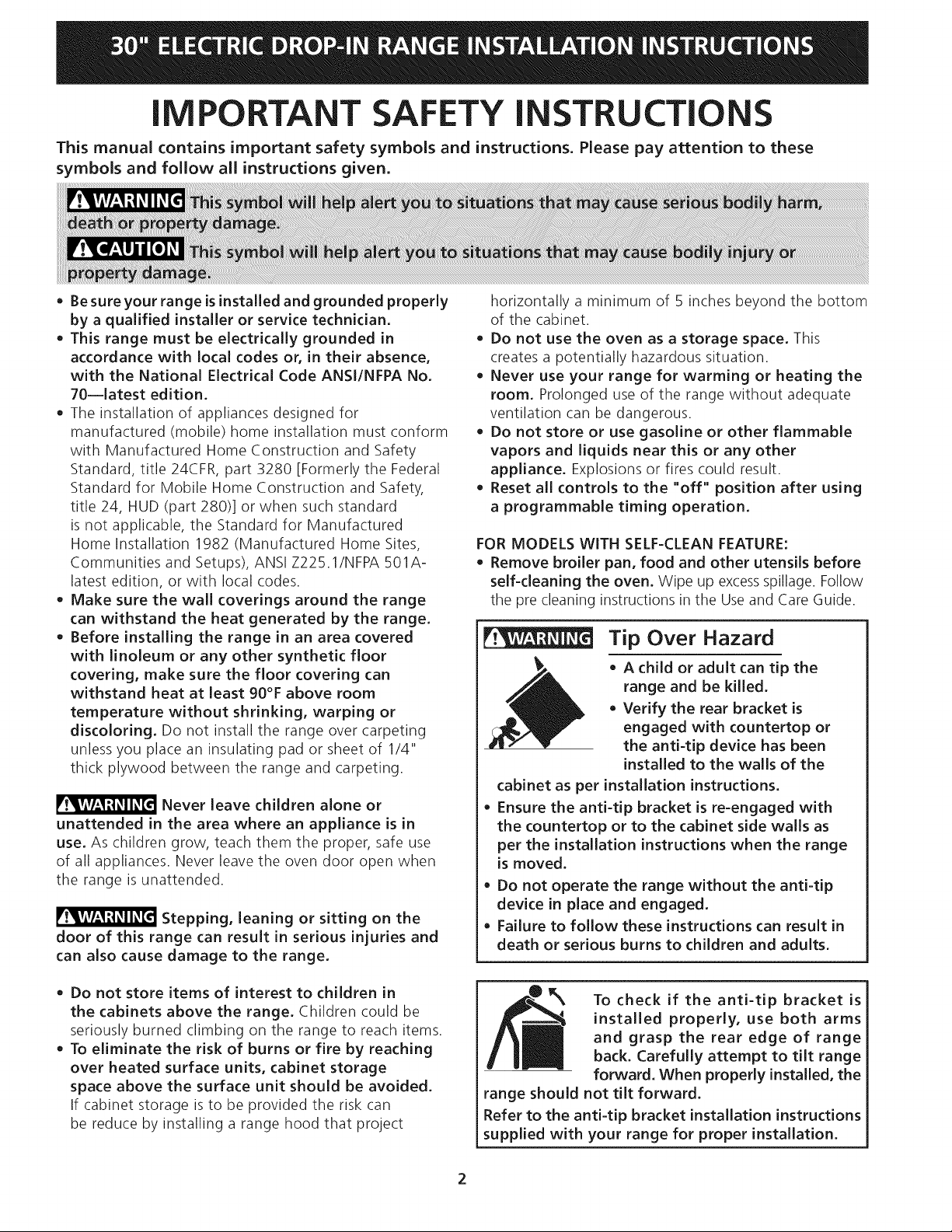
Tip Over Hazard
A child or adult can tip the
range and be killed.
Verify the rear bracket is
engaged with countertop or
the anti-tip device has been
installed to the walls of the
cabinet as per installation instructions.
Ensure the anti-tip bracket is re=engaged with
the countertop or to the cabinet side walls as
per the installation instructions when the range
is moved.
Do not operate the range without the anti-tip
device in place and engaged.
Failure to follow these instructions can result in
death or serious burns to children and adults.
Do not store items of interest to children in
the cabinets above the range. Children could be
seriously burned climbing on the range to reach items.
To eliminate the risk of burns or fire by reaching
over heated surface units, cabinet storage
space above the surface unit should be avoided.
If cabinet storage isto be provided the risk can
be reduce by installing a range hood that project
To check if the anti=tip bracket is
installed properly, use both arms
and grasp the rear edge of range
back. Carefully attempt to tilt range
forward. When properly installed, the
range should not tilt forward.
Refer to the anti-tip bracket installation instructions
supplied with your range for proper installation.
Page 3
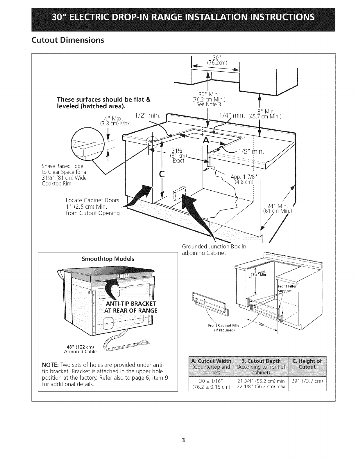
Cutout Dimensions
30"
(76.2cm) I
These surfaces should be flat &
leveled (hatched area),
11/2"Max. 1/2" rain.
(3.8 cm) Max.
ShaveRaisedEdge
to ClearSpacefor a
311/2'' (81cm)Wide
Cooktop Rim.
Locate Cabinet Doors
1" (2.5 cm) Min.
from Cutout Opening
Smoothtop Models
(76.2cm.MLn.)
SeeNote 3 I
18" Min.
rain. (45.7cm Min.)
1/2" _nin.
C
/
24" Min.
cm Min.
j'
Grounded Junction Box in
adjoining Cabinet
ANTI-TIP BRACKET
AT REAR OF RANGE
48" (122 cm)
Armored Cable
NOTE: Two sets of holes are provided under anti-
tip bracket. Bracket isattached in the upper hole
position at the factory. Refer also to page 6, item 9
for additional details.
'N.
Front Cabinet Filler
(If required)
30 _+1/16" 21 3/4" (55.2 cm) min 29" (73.7 cm)
(76.2 _+0.15 cm) 22 1/8" (56.2 cm) max
3
Page 4
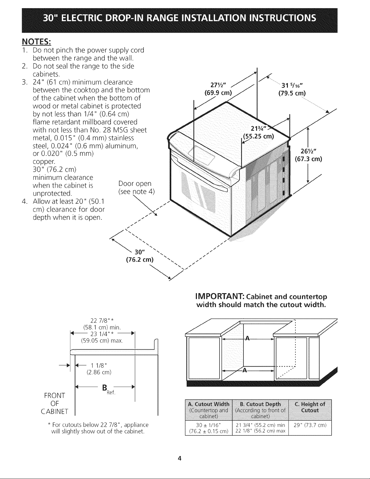
NOTES:
1. Do not pinch the power supply cord
between the range and the wall.
2. Do not seal the range to the side
cabinets.
3. 24" (61 cm) minimum clearance
between the cooktop and the bottom
of the cabinet when the bottom of
wood or metal cabinet is protected
by not lessthan 1/4" (0.64 cm)
flame retardant millboard covered
with not less than No. 28 MSG sheet
metal, 0.015" (0.4 mm) stainless
steel, 0.024" (0.6 mm) aluminum,
or 0.020" (0.5 mm)
copper.
30" (76.2 cm)
minimum clearance
when the cabinet is
unprotected.
4. Allow at least 20" (50.1
cm) clearance for door
depth when it is open.
Door open
(see note 4)
I
I
271/2" """ 31 s/16"
(69.9 cm) (79.5 cm)
55.25 crn)
261/2"
(67.3 crn)
/ /
(76.2 cm) "-. i j
22 7/8" *
(58.1 cm) min.
(59.05 cm) max. r
_ 23 1/4"*
_/_ 11/8"
" (2.86 cm)
_!_ BRef
FRONT
OF
CABINET
* For cutouts below 22 7/8", appliance
will slightly show out of the cabinet.
IM PO RTANT: Cabinet and countertop
width should match the cutout width.
30 _+1/16" 21 3/4" (55.2 cm) min 29" (73.7 cm)
(76.2 _+0.15 cm) 22 1/8" (56.2 cm) max
4
Page 5
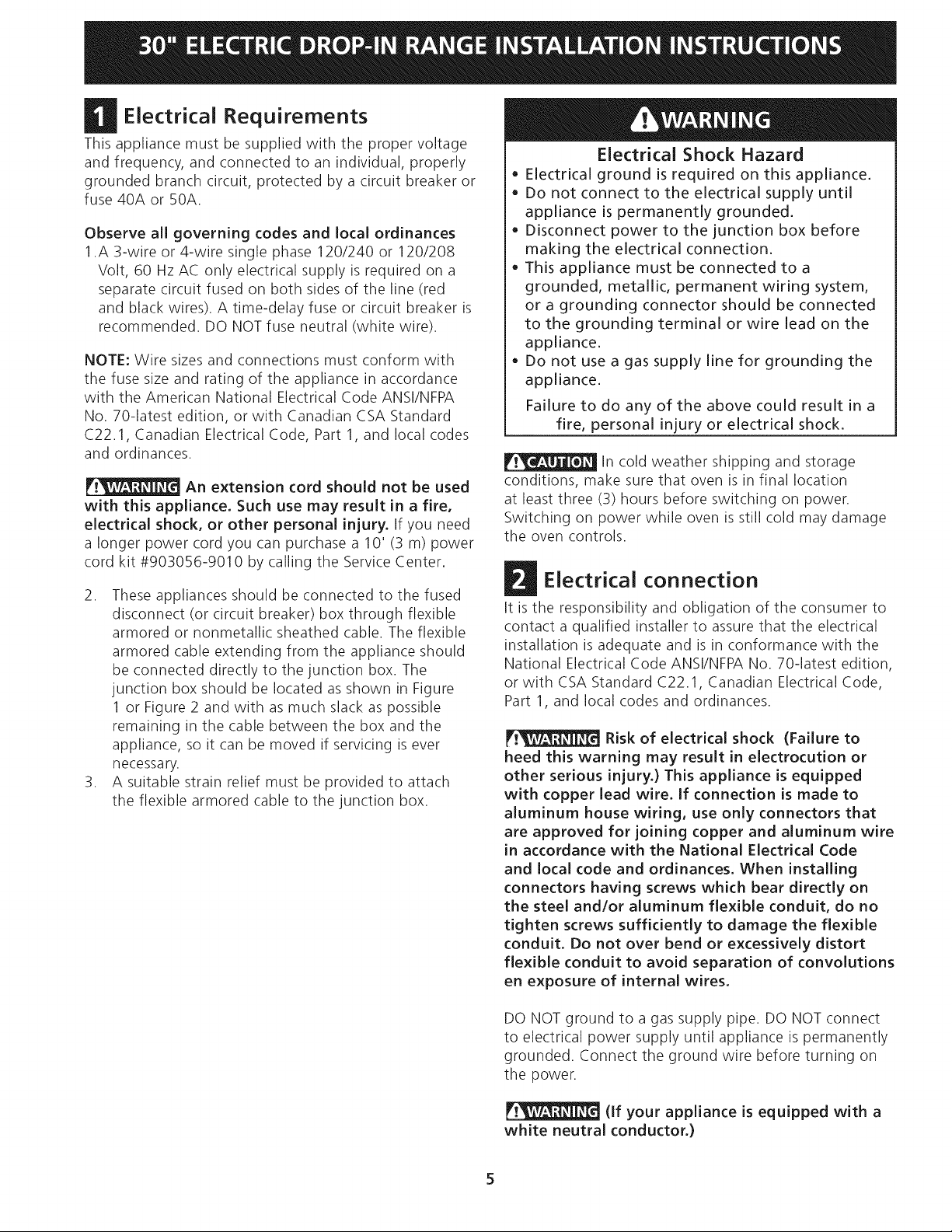
D Electrical Requirements
This appliance must be supplied with the proper voltage
and frequency, and connected to an individual, properly
grounded branch circuit, protected by a circuit breaker or
fuse 40A or 50A.
Observe all governing codes and local ordinances
1.A 3-wire or 4-wire single phase 120/240 or 120/208
Volt, 60 Hz AC only electrical supply is required on a
separate circuit fused on both sides of the line (red
and black wires). A time-delay fuse or circuit breaker is
recommended. DO NOT fuse neutral (white wire).
NOTE: Wire sizes and connections must conform with
the fuse size and rating of the appliance in accordance
with the American National Electrical Code ANSI/NFPA
No. 70-latest edition, or with Canadian CSA Standard
C22.1, Canadian Electrical Code, Part 1, and local codes
and ordinances.
An extension cord should not be used
with this appliance. Such use may result in a fire,
electrical shock, or other personal injury. If you need
a longer power cord you can purchase a 10' (3 m) power
cord kit #903056-9010 by calling the Service Center.
2. These appliances should be connected to the fused
disconnect (or circuit breaker) box through flexible
armored or nonmetallic sheathed cable. The flexible
armored cable extending from the appliance should
be connected directly to the junction box. The
junction box should be located as shown in Figure
1 or Figure 2 and with as much slack as possible
remaining in the cable between the box and the
appliance, so it can be moved if servicing is ever
necessary.
3. A suitable strain relief must be provided to attach
the flexible armored cable to the junction box.
Electrical Shock Hazard
• Electrical ground is required on this appliance.
• Do not connect to the electrical supply until
appliance is permanently grounded.
• Disconnect power to the junction box before
making the electrical connection.
• This appliance must be connected to a
grounded, metallic, permanent wiring system,
or a grounding connector should be connected
to the grounding terminal or wire lead on the
appliance.
• Do not use a gas supply line for grounding the
appliance.
Failure to do any of the above could result in a
fire, personal injury or electrical shock.
In cold weather shipping and storage
conditions, make sure that oven is in final location
at least three (3) hours before switching on power.
Switching on power while oven is still cold may damage
the oven controls.
Electrical connection
It is the responsibility and obligation of the consumer to
contact a qualified installer to assure that the electrical
installation is adequate and is in conformance with the
National Electrical Code ANSI/NFPA No. 70-latest edition,
or with CSA Standard C22.1, Canadian Electrical Code,
Part 1, and local codes and ordinances.
Risk of electrical shock (Failure to
heed this warning may result in electrocution or
other serious injury.) This appliance is equipped
with copper lead wire. if connection is made to
aluminum house wiring, use only connectors that
are approved for joining copper and aluminum wire
in accordance with the National Electrical Code
and local code and ordinances. When installing
connectors having screws which bear directly on
the steel and/or aluminum flexible conduit, do no
tighten screws sufficiently to damage the flexible
conduit. Do not over bend or excessively distort
flexible conduit to avoid separation of convolutions
en exposure of internal wires.
DO NOT ground to a gas supply pipe. DO NOT connect
to electrical power supply until appliance is permanently
grounded. Connect the ground wire before turning on
the power.
(If your appliance is equipped with a
white neutral conductor.)
Page 6
Thisapp(ianceismanufacturedwith awhite neutral
powersupplyandaframeconnectedcopperwire.
Theframeisgroundedbyconnectionof grounding
leadto neutralleadattheterminationof the
conduit,if usedinUSA,in anewbranchcircuit
installation(1996NEC),mobilehome,recreational
vehicles,where(ocalcodedo not permitgrounding
troughtheneutral(white)wireor in Canada,
disconnectthewhite andgreenleadfromeach
otherandusegroundleadto groundunit in
accordancewith localcodes,connectneutrallead
to branchcircuit-neutralconductorinusualmanner
seeFigure4.If yourapplianceisto beconnected
to a3wire groundedjunctionbox(USonly),
wherelocalcodepermitconnectingtheappliance-
groundingconductorto theneutral(white)see
Figure 3.
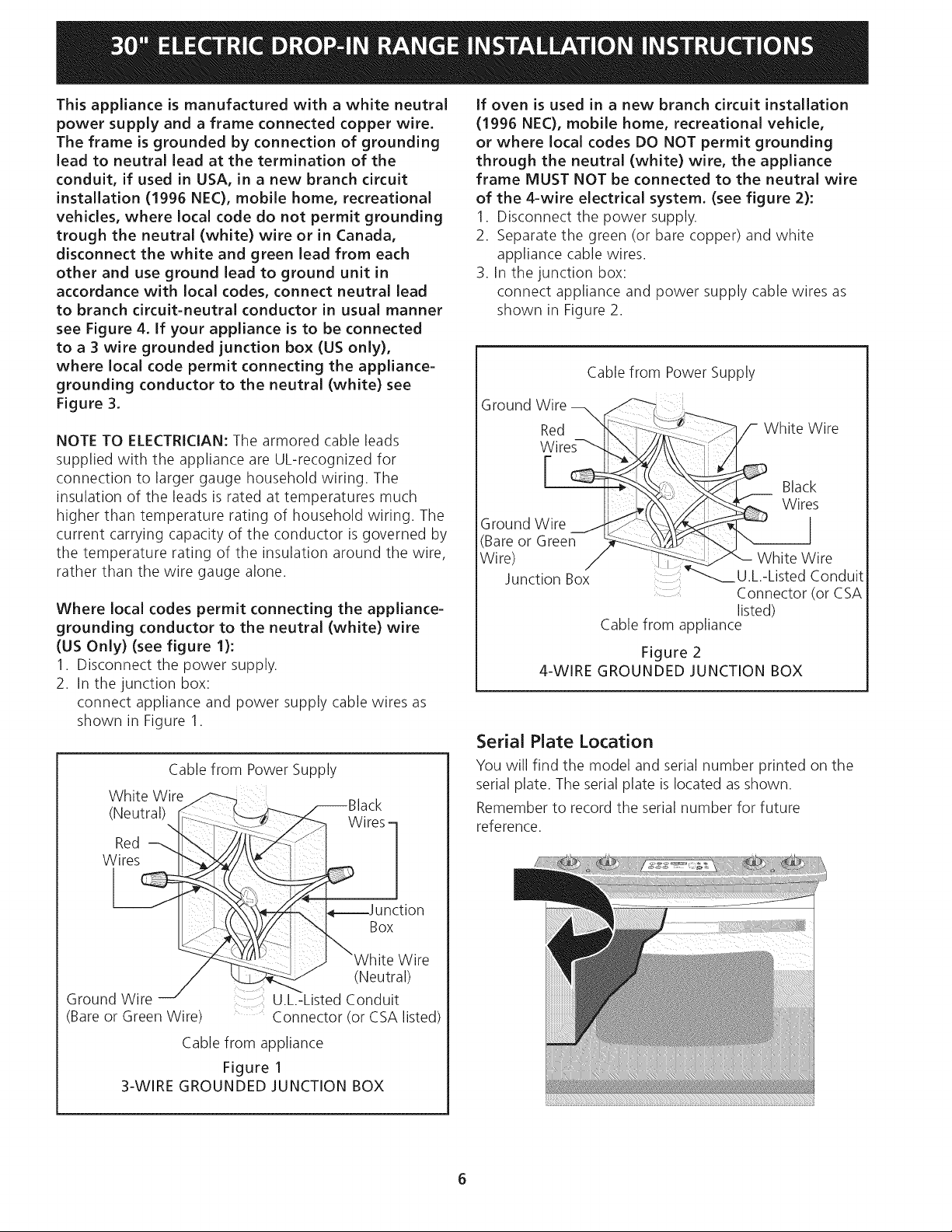
If oven is used in a new branch circuit installation
(1996 NEC), mobile home, recreational vehicle,
or where local codes DO NOT permit grounding
through the neutral (white) wire, the appliance
frame MUST NOT be connected to the neutral wire
of the 4-wire electrical system. (see figure 2):
1. Disconnect the power supply.
2. Separate the green (or bare copper) and white
appliance cable wires.
3. In the junction box:
connect appliance and power supply cable wires as
shown in Figure 2.
Cable from Power Supply
NOTE TO ELECTRICIAN: The armored cable leads
supplied with the appliance are UL-recognized for
connection to larger gauge household wiring. The
insulation of the leads is rated at temperatures much
higher than temperature rating of household wiring. The
current carrying capacity of the conductor is governed by
the temperature rating of the insulation around the wire,
rather than the wire gauge alone.
Where local codes permit connecting the appliance-
grounding conductor to the neutral (white) wire
(US Only) (see figure 1):
1. Disconnect the power supply.
2. In the junction box:
connect appliance and power supply cable wires as
shown in Figure 1.
Cable from Power Supply
White Wire _
(Neutral).,[" _ rCKs-
Red _:z-
Red __ _,_"--_'-_
Ground Wire __
____ Black
Ground Wire
(Bare or
Wire) Green __
Junction Box
4-WIRE GROUNDED JUNCTION BOX
Serial Plate Location
You will find the model and serial number printed on the
serial plate. The serial plate is located as shown.
Remember to record the serial number for future
reference.
i
---___ U.L.-Listed Conduit
Cable from appliance
Figure 2
hite Wire
s
White Wire
Connector (or CSA
listed)
_---J I _\_/z_,. I_---J uncti° n
Ground Wire J sted c(Nned_[_l)
(Bare or Green Wire) Connector (or CSA listed)
Cable from appliance
Figure 1
3-WIRE GROUNDED JUNCTION BOX
Page 7

Range Installation
The electrical power to the range must
be shut off while line connections are being made.
Failure to do so could result in serious injury or death.
Countertop Preparation
• The cooktop sides of the range fit over the cutout
edge of your countertop.
• If you have a square finish (flat) countertop, no
countertop preparation is required. Cooktop sides lay
directly on edge of countertop.
• Formed front-edged countertops must have molded
edge shaved flat 3/4" (1.9 cm) from each front corner
of opening (Figure 3).
• Tile countertops may need trim cut back 3/4"(1.9
cm) from each front corner and/or rounded edge
flattened (Figure 3).
• If the existing cutout width is greater than
30 1/16" (76,4 cm), reduce the 3A" (1.9 cm)
dimension.
back at front corners of
countertop opening.
Figure 3
This range is designed to hang from the countertop. It
does not rest on the floor.
Be sure the bottom of any wall cabinets are a minimum
of 30" (76.2 cm) above the rangetop area.
To eliminate the hazard or reaching over heated surface
units, cabinet storage space located above the surface
units should be avoided. If cabinet storage is to be
provided, the hazard can be reduced by installing a range
hood that projects horizontally a minimum of 5" (12.7
cm) beyond the bottom front edge of the cabinets.
Important Note: Door removal is not a requirement for
installation of the range, but is an added convenience.
The appliance should be placed on a table or the front of
the appliance should be raised to be able to fully open
the door. Please refer to the Useand Care Guide for
oven door removal instructions.
1. Install base cabinets 30" (76.2cm) apart, and be
sure they are plumb and level before attaching to
countertop.
2. Cut countertop exactly as shown in Figure 1. Shave
raised edge level to clear 31 1/2" (81cm) wide rim
on rolled edge styled countertops.
3. Install the wiring junction box in an adjoining cabinet
or under the floor (range has 48"/122cm of conduit).
Cut 1-1/4" (3.2cm) hole to bring conduit to the
junction box.
4. To provide an optimum installation, the top surface
of the countertop must be level and flat (lie on the
same plane) around the 3 sides that are adjacent to
range cooktop. Proper adjustments to make the top
flat should be made or gaps between the countertop
may occur.
5. _ To reduce the risk of damaging your
appliance, do not handle or manipulate it by the
ceramic glass. Manipulate with care.
6. Move range in front of cabinet opening.
7. Push the electric conduit through the hole and
attach it to the junction box. Leave enough slack in
the conduit to allow the range to be pulled forward
several inches for service if necessary.
8. Oven door is heavy. It is advisable to remove door
and eliminate its weight as range is lifted into
position. See oven door removal instructions in
the Use and Care Guide. NEVER lift the appliance
by the control panel doing so may damage_ the
control panel. Lift the range into position on
the countertop and make sure the appliance is
centered in the cutout opening to be sure that
the flanges of the upper side panel are sitting
on the countertop to avoid glass breakage.
7
Page 8

D Anti-tip Bracket installation
A. Preferred Anti-tip installation (All models)
1. The range is equipped with an anti-tip bracket
attached to the back of the range with two screws.
If countertop thickness is greater than 1/2" (1.3cm),
relocate anti-tip bracket to the lower position 1/4"
(6.4 mm) below (see figure 4).
2. Anti-slide brackets Installation (Figure 5):
A.Place the range so that it is about 6" out of the
cabinet.
B. Insert from below the shoulder screws in the
bottom bracket (one on each side)
C. Slide the range into its final position.
D. Position the "L" bracket against the side of the
cabinet so that it is retained by the shoulder
screws, hold bracket and mark the holes on the
inside of the cabinet. Drill pilot holes into cabinet
where you just marked (Caution should be taken
to avoid drilling through the opposite side of the
cabinet). Attach the "L" bracket to the cabinet
with the screws provided (don't forget to insert
the shoulder screw into the bracket).
E. Repeat steps D on the other side.
3. Install the decorative lower trim under the door
using the screws provided with the range.
Figure 5
B. Alternate Anti tip installation (All models)
1. The range is equipped with two anti-tip "L" brackets
located on each side of the range with two screws
(see figure 6).
Figure 4
Figure 6
Page 9
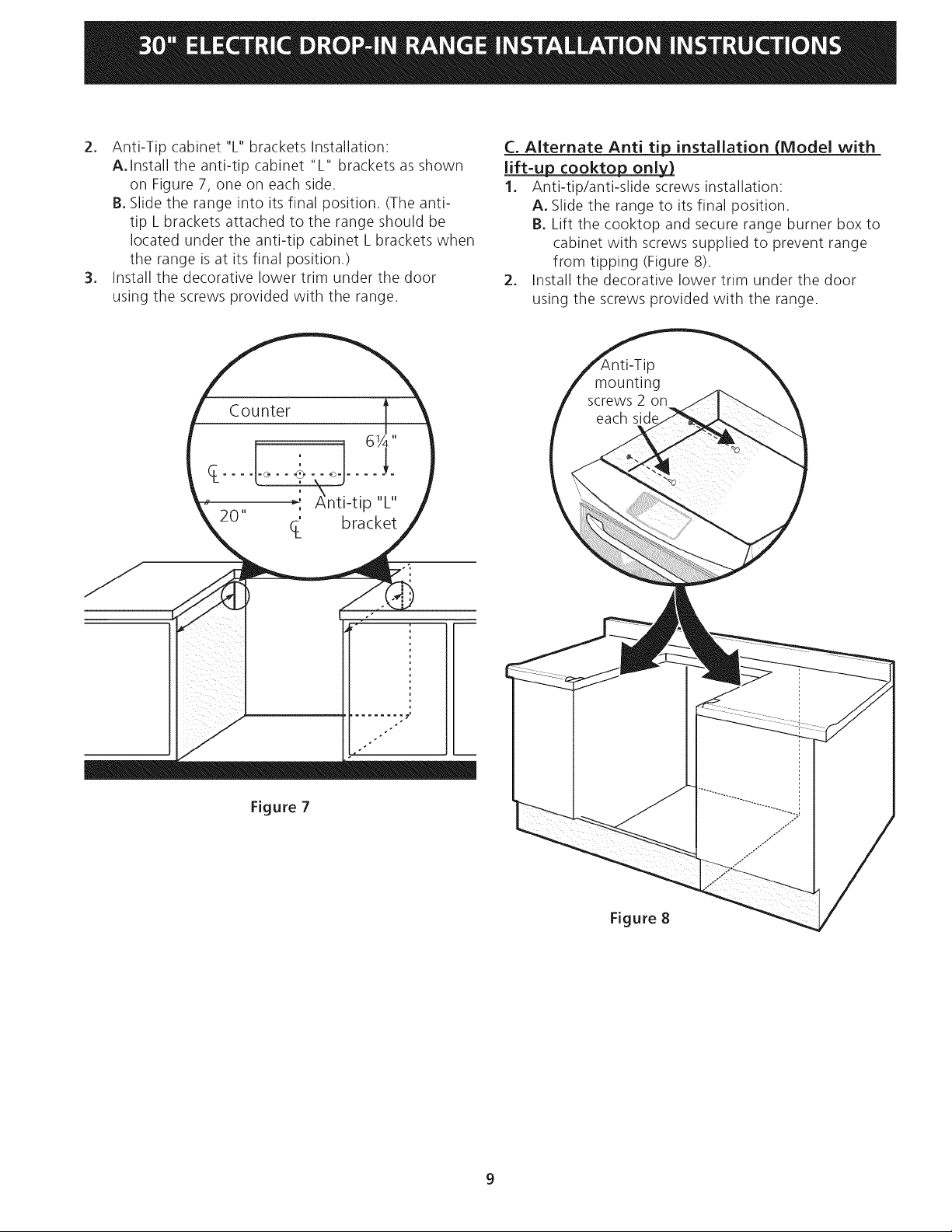
2. Anti-Tipcabinet"L"bracketsInstallation:
A.Installtheanti-tipcabinet"L"bracketsasshown
onFigure7,oneoneachside.
B.Slidetherangeintoitsfinalposition.(Theanti-
tipLbracketsattachedto therangeshouldbe
locatedundertheanti-tipcabinetLbracketswhen
therangeisatitsfinalposition.)
3. Installthedecorativelowertrimunderthedoor
usingthescrewsprovidedwiththerange.
Counter
,' _,nti-tip "L"
20" C_ bracket
C. Alternate Anti tip_ installation (Model with
lift=up cooktop onl_
1. Anti-tip/anti-slide screws installation:
A. Slide the range to its final position.
B. Lift the cooktop and secure range burner box to
cabinet with screws supplied to prevent range
from tipping (Figure 8).
2. Install the decorative lower trim under the door
using the screws provided with the range.
i_ ii ili
ii ii iii i _i
iiI i i _ii
i i
Figure 7
Figure 8
9
Page 10

Checking Operation
Some models have manual controls. Refer to the Owner's
Guide and check all controls for correct operation.
Some models are equipped with an electronic oven
control. Each of the functions has been factory checked
before shipping. However, it is suggested that you verify
the operation of the electronic oven controls once more.
Refer to the Owner's Guide for operation. Follow the
instructions for the Clock, Timer, Bake, Broil, Convection
(some models) and Clean (some models) functions.
Bake-After setting the oven to 350°F (177°C) for baking,
the lower element in the oven should become red.
Broil-When the oven is set to BROIL, the upper element
in the oven should become red.
Clean (some models)-When the oven is set for a self-
cleaning cycle, the upper element should become red
during the preheat portion of the cycle. After reaching
the self-cleaning temperature, the lower element will
become red.
Convection (some models)-When the oven is set for
convection baking or roasting, both elements cycle on
and off alternately and the convection fan will turn. The
convection fan will stop turning when the oven door is
opened during convection baking or roasting.
Model and Serial Number Location
The serial plate is located along the side of the oven door
in the open position.
When ordering parts for or making inquires about your
oven, always be sure to include the model and serial
numbers and a lot number or letter from the serial plate
on your oven.
Before You Call for Service
Read the Avoid Service Checklist and operating
instructions in your Owner's Guide. It may save you time
and expense. The list includes common occurrences that
are not the result of defective workmanship or materials
in this appliance.
Refer to the warranty in your Owner's Guide for our
toll-free service number and address. Please call or write
if you have inquiries about your product and/or need to
order parts.
IMPORTANT NOTE: A fan inside the upper rear part
above the oven (some models) provides additional
cooling of the oven electrical and electronic components.
The fan will continue to run after the oven has been
operating at high temperatures.
10
Page 11

f
INSTRUCCIONE
f
ESTUFA ELECTRICA
DE INSTALACION
|l
EMPOTRABLE DE
LA INSTALACION Y EL SERVICIO DEBEN SER EFECTUADOS POR UN INSTALADOR
CALIFICADO.
IMPORTANTE: GUARDE ESTAS INSTRUCCIONES PARA USO DEL iNSPECTOR LOCAL DE
ELECTRICIDAD. LEA Y GUARDE ESTAS INSTRUCCIONES PARA REFERENCIA FUTURA.
Estados Unidos
PARA SU SEGURIDAD: No aimacene ni utilice gasolina
u otros vapores y liquidos inflamables en ia proximidad de este o de
cuaiquier otto artefacto.
Tabla de materias
Importantes instrucciones de seguridad .......................... 12
Gabinete dimensiones ............................................... 13-14
Requerimientos el_ctricos............................................... 15
Conexi6n el_ctrica .................................................... 15-16
Ubicaci6n de la placa de serie ........................................ 16
Instalaci6n de la estufa ................................................... 17
Instrucciones de instalaci6n de
la fijaci6n anti-indinaci6n .......................................... 18-19
Comprobaci6n del Funcionamiento ................................ 20
UbicaciOn del numero de modelo y de serie ................... 20
Antes de Ilamar al servicio .............................................. 20
Notas importantes para el
instalador
1. Leatodas las instrucciones antes de instalar la cocina.
2. Retire todo material de empaquetado del homo y de
la gaveta de entibiado antes de conectar el suministro
el_ctrico a la cocina.
3. Observe todo cOdigo o reglamento.
4. AsegOrese de dejar estas instrucciones con el
consumidor
Impreso en Canada
Nota importante para el
consumidor
Mantenga estas instrucciones con el manual del usuario
para futuras referencias.
P/N 318201627 (1209) Rev.B
English - pages 1-10
Espahol- p5ginas 11-20
Page 12

IMPORTANTES INSTRUCCIONES DE SEGURIDAD
Este manual contiene importantes mensajes de seguridad. Siempre lea y obedezca todo mensaje de
seguridad.
• Aseg_rese que su cocina est_ instalada y
conectada adecuadamente a tierra pot un
instalador calificado o un t_cnico de servicio.
• Esta cocina debe set conectada a tierra
el_ctricamente de acuerdo con los c6digos locales,
o de no existir, con la National Electrical Code
ANSI/NFPA No.70- _ltima edicion.
• La instalaciOn de electrodom_sticos destinados
para casas (movibles) deben conformarse con la
Manufactured Home Construction and Safety
Standard, titulo 24CFR, parte 3280 [antiguamente
la Federal Standard for Mobile Home Construction
and Safety, titulo 24, HUD (parte 280)] o cuando este
c6digo no se aplica, la Standard for Manufactured
Home Installation 1982 (Manufactured Home sites,
communities and setups); ANSIZ225.1/NFPA 501A-
01tima edici6n o con c6digos locales.
• Asegerese que el empapelado de pared alrededor
de la cocina pueda resistir el calor generado pot la
cocina.
• Antes de instalar la cocina en una _rea cubierta
de linoleo o cualquier otro revestidos de piso
sint_tico, asegurese que Cste pueda resistir al
menos 90°F sobre la temperatura de la pieza sin
encogerse, ladearse o descolorareis. No instale la
cocina encima de una alfombra a menos que coloque
una placa de aislamiento o una plancha de 1/4" de
madera entre la cocina y el alfombrado.
Nunca deje a los ni_os solos o
sin cuidado en el area donde el electrodom_stico
et_ en uso. A medida que los niflos crezcan, ens_fleles
el uso adecuado de los electrodom_sticos. Nunca deje
la puerta del homo abierta cuando la cocina est_ sin
supervisi6n.
Pisar, apoyarse o sentarse en
las puertas o los cajones de la cocina pueden causar
graves heridas y tambi_n daffar la cocina.
• No coloque cosas que atraigan a los niffos sobre
los gabinetes encima de la cocina. Los niflos
podrian sufrir quemaduras tratando de alcanzarlos.
• Para evitar riesgos de quemaduras o incendios
al tocar superficies calientes, se deben evitar los
armarios sobre la superficie de los quemadores.
Si existe un armario, se pueden reducir los
riesgos instalando una campana que se extienda
horizontalmente en un minimo de 5" por sobre la
parte inferior de los armarios.
* No use el homo como espacio de almacenamiento.
Esto crea una situaciOn muy peligrosa.
* Nunca use su cocina para calentar la pieza. El
uso prolongado de la cocina sin ventilaci6n adecuada
puede ser peligroso.
* No guarde o use gasolina u otros vapores
inflamables y liquidos cerca de _ste o cualquier
otto electrodom_stico. Esto podria causar una
explosi6n o un incendio.
* Vuelva a programar todos los controles a la
posicion "off" (apagado) despu_s de haber
utilizado el conteo contador autom_tico.
PARA LOS MODELOS CON AUTO-LIMPIEZA:
* Retire el rostisador, la comida y otros utensilios
antes de auto-limpiar el homo. Limpie todo exceso
de derrames. Siga las instrucciones para la pre-limpieza
en el Manual del usuario.
_o de voicamiento
* Un ni_o o adulto puede volcar la
estufa y acabar muerto.
* Verificar que el braquet trasero
este calibrado con la cubierta o
el utensilio del anti-vuelco sea
instalado en las paredes del cabinete como la
indican las instrucciones.
* Asegurar que el braquet antivuelco sea calibrado con
la cubierta o los lados de la cabina asi como Io indican
las instrucciones cuando la estufa sea movida.
* No utilice la estufa sin el dispositivo antivuelco
instalado y acoplado,
* Si no se siguen estas instrucciones, se puede provocar
la muerte o quemaduras graves en niffos y adultos,
Para verificar si la fijaciones de anti-
indinaci6n est_ instalado correctamente,
sostenga el borde trasero de la parte
trasera de la estufa usando ambos brazos.
Intente inclinar la estufa hacia adelante
con cuidado. Si est_ instalada correctamente, la estufa
no deberia inclinarse hacia adelante.
Consulte las instrucciones de instalacion del soporte
antivuelco proporcionadas con la estufa para instalarlo
adecuadamente.
12
Page 13

Gabinete Dimensiones
30"
Lijela parte
elevadedel borde
para obtenerlas
311/2'' (81cm)de
anchodel reborde
de la planchade
cocinar.
Ubique las puertas de
los armarios un minimo
de 1" de la abertura.
Modelos de superfide lisa
C
VeaNote 3 I
18" Min.
',rain. (45, cm Min.)
311/2''
(81
Exacto
App. 1-7/8"
(4,8 cm)
La caja de empaJmes de
conexi6n con la tJerra.
Cable Blindado
NOTA: Hay dos juegos de agujeros debajo del
soporte antivuelco. Elsoporte viene colocado, desde
la f_ibrica, en el agujero superior. Refi6rase para
paginar 14, el articulo 9 para detalles adicionales.
Front Cabinet Fi[[er
(If required)
30 _+1/16" 21 3/4" (55.2cm) rain 22 29"
(76.2 _+0.15cm) 1/8" (56.2cm) max (73.7cm)
13
Page 14

NOTAS:
1.No pellizque el cord6n electrico entre la estufa y la pared.
2.No selle la estufa a los armarios de lado.
3.Un espacio mfnimo de 24" (61 cm)
entre la superficie de la estufa y el
fondo del armario cuando el fondo
del armario de madera o metal est,1
protegido por no menos de 1/4"
(0.64 cm) de madera resistente
al fuego cubierta por una I_imina
met_ilica de MSG, n0mero 28,
0.015" (0.4 ram) de acero inoxidable,
0.024" (0.6 ram) de aluminio, o
0.02" (0.5 ram) de cobre.
Un espacio mfnimo
de 30" (76.2 cm)
cuando el armario
no est,1 protegido.
4.Deje por los 20"
(50.! cm) de
espacio libre para
la profundidad de
la puerta cuando
esta abierta.
55.25 cm)
261/2"
(67.3 cm)
22 7/8" *
(58.1 cm) rain.
1)I
(59.05 cm) max. ["
__ 23 1/4"*
i
k
_-- 11/8"
-- (2.86 cm)
PARTE _ BRef.
DELANTERA
DEL
ARMARIO
• Para los recortados menos que 22 7/8", el
electrodomestico apareceria ligeramente en el
exterior del armario.
IMPORTANTE: El ancho de la cubierta y el
armario debe de set igual al ancho del torte.
30 _+1/16" 21 3/4" (55.2cm) min 29" (73.7cm)
(76.2 _+0.15cm) 22 1/8" (56.2cm)max
14
Page 15

Requerimientos Electricos
Se debe proveer el voltaje y la frecuencia apropiados
a este electrodom_stico, y conectarse a un circuito
individual correctamente puesto a tierra, protegido por un
interruptor o un fusible de 40A o 50A
Observe todos los c6digos que gobiernan y
ordenanzas locales
1. Un cable de 3 o 4 alambres monof_isico 120/240 o
120/208 voltios, 60 hertzios es la Onicafuente el_ctrica
que requiere en un circuito separado en ambos lados de
la linea (alambre negro y alambre rojo) (serecomienda
un fusible o un interruptor de retraso de tiempo). No
funda a cable neutro (alambre blanco).
NOTA: Lostamahos y las conexiones del alambre deben
conformarse con el tamaho del fusible y el grado de la
aplicaciSn de acuerdo con el cSdigo El_ctrico Nacional
Americano ANSI/NFPANo. 70- ultima ediciSn, o con
el est_indar CSA canadiense C22.1, cSdigo el_ctrico
canadiense, parte 1, y cSdigos y ordenanzas locales.
No se debera usar extensiones
para enchufar este electrodom_stico, Esto podria
causar un incendio, choque el_ctrico u otto tipo
de da_o personal. Si usted necesita un cable mas
largo, puede ordernar un cable de 10" kit 903056-9010
llamando al centro de Servicio.
2. Esteelectrodom_stico debe conectarse a la caja de
fusibles (o de cortocircuito), por medio de un cable
blindado flexible o un cable con forro no met_ilico. El
cable blindado flexible que va desde el electrodom_stico
debe de estar conectado directamente a la caja de
empalme. La caja de empalme debe de estar Iocalizada
en el lugar que se indica en la Figura 1 o 2, dejando
tanto exceso de cable como sea posible entre la caja y el
electrodom_stico, de forma que asi el electrodom_stico
se pueda mover f_icilmente, sifuera necesario para
hacer una reparaciOn.
3. Se debe de usar un conector que reduzca la tirantez de
una forma adecuada para unir el cable blindado flexible
a la caja de empalme.
Riesgo de choque el_ctrico
+ Una puesta a tierra se requiere en este aparato,
+ No Io conecte a la corriente electrica hasta que el
aparato haya sido puesto a tierra.
+ Desconecte la corriente electrica a la caja de
empalmes antes de hacer la conexi6n electrica,
+ Este aparato debe estar conectado con un
sistema de alambres puesto en tierra, met_lico
y permanente o un conector de puesta a tierra
debe conectarse al terminal de puesta a tierra o el
alambre conductor en al aparato.
+ No utilice el suministro de gas para hacer la puesta
a tierra.
La falta de cualquiera de las instrucdones
mendonadas podria resultar en un incendio, choque
electrico o lesiones personales,
Conexi6n electrica
El usuario tiene la responsabilidad personal y obligaciOn
de utilizar un instalador calificado, para asegurar que la
instalaciSn el_ctrica est,1hacha de forma adecuada y est,1
conforme con el CSdigo El_ctrico Nacional ANSI/NFPA
No. 70-01tima ediciSn en los Estados Unidos, o el CSdigo
El_ctrico Canadiense CSA Standard C22.1, Part 1, en
Canada1.
Riesgo de choque el¢ctrico
(El no prestar atendon a esta advertencia puede
resultar en electrocucion u otras lesiones graves,)
Este electrodom_stico est_ equipado con alambre
de cobre, Si se va a conectar con cableado de
aluminio del hogar, utilizar _nicamente conectores
que est_n aprobados para unit cobre y aluminio de
acuerdo al Codigo National El_ctrico (NEC pot sus
siglas en ingles) y leyes y codigos locales, AI instalar
conectores con torniHos que empujen directamente
contra el acero y/o aluminio del conducto flexible,
no apretar los tornillos sufidentemente que da_en
el conducto flexible, No doblar de m_s o deformar
el conducto flexible para evitar separar el espiral y
descubrir los alambres internos,
En cuanto alas condiciones de
despacho y almacenamiento en el invierno, aseg0rese de
que el homo llegue a su destino final como minimo tres
(3) horas antes de encenderlo. Si se enciende el homo
cuando a0n est,1frio, se pueden dahar los controles.
NO conecte el alambre puesto a tierra a una tuberia
de suministro de gas. NO conecte el suministro de
energia el_ctrica hasta que el electrodom_stico haya sido
permanentemente puesto a tierra. Conecte el alambre
de puesto a tierra antes de enchufar por primera vez el
electrodom_stico.
(Si su electrodom_stico est_
equipado con un conductor neutro blanco,)
15
Page 16
Esteelectrodom6sticoest_fabricadoconun
suministroel6ctriconeutroblancoy unalambrede
cobreconectadoal armazon.Elarmazonestapuesto
atierrapot unenlacedela conexi6n a tierra con la
conexi6n del neutro al final de la linea el6ctrica, si es
usado en los estados unidos una nueva instalad6n
de drcuito de bifurcad6n (1996 NEC), casa rodante,
vehiculos recreacionales, o donde los c6digos locales
no permitan poner a tierra mediante el neutro
(blanco) o en Canada, desconectar la conexi6n
blanca de la verde y utilizar la conexi6n a tierra para
poner a tierra la unidad de acuerdo a los c6digos
locales, conectar el neutro al drcuito de bifurcaci6n-
conductor neutro de manera usual. Vet Figura 4. Si
su electrodom6stico va a set conectado a una caja de
conexion puesta a tierra de 3 cables (en los estados
unidos solamente), donde los c6digos locales
permitan conectar el conductor de poner a tierra-
electrodom6stico con el neutro (blanco) vet Figura 3.
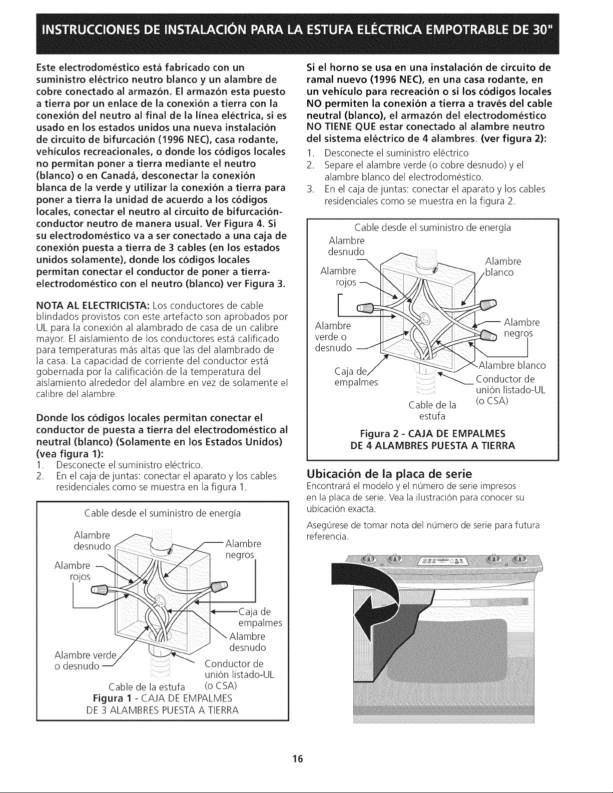
Si el horno se usa en una instalacion de circuito de
ramal nuevo (1996 NEC), en una casa rodante, en
un vehiculo para recreacion o si los codigos locales
NO permiten la conexion a tierra a traves del cable
neutral (blanco), el armazon del electrodom6stico
NO TIENE QUE estar conectado al alambre neutro
del sistema el6ctrico de 4 alambres. (ver figura 2):
1. Desconecte el suministro el_ctrico
2. Separe el alambre verde (o cobre desnudo) y el
alambre blanco del electrodom@stico.
3. En el caja de juntas: conectar el aparato y los cables
residenciales como se muestra en la figura 2.
Cable desde el suministro de energia
Alambre
desnudo _-_._
--_, S _, Alambre
Alamb.re "$_..........._ _.._' _/blanco
NOTA AL ELECTRICISTA: Los conductores de cable
blindados provistos con este artefacto son aprobados pot
UL para la conexi6n al alambrado de casa de un calibre
mayor. El aislamiento de los conductores est5 calificado
para temperaturas ross altas que las del alambrado de
la casa. La capacidad de corriente del conductor est5
gobernada pot la calificaci6n de la temperatura del
aislamiento alrededor del alambre en vez de solamente el
calibre del alambre.
Donde los c6digos locales permitan conectar el
conductor de puesta a tierra del eiectrodom6stico al
neutral (blanco) (Solamente en los Estados Unidos)
(vea figura 1):
1. Desconecte el suministro el_ctrico.
2. En el caja de juntas: conectar el aparato y los cables
residenciales como se muestra en la figura 1.
Cable desde el suministro de energia
Alambre -------__
desnudo ¢ k
/_Alambre
,..1
Alambre--,__" _[_/J/((:_-
,_kegros
rojosL_
A,ambre ._...i_-r_ _i _] _ A,ambre
desnudo
Caja _ f_ _ _AITmbre bancO
empalmes _ Conductor de
Figura 2 - CAJA DE EMPALMES
DE 4 ALAMBRES PUESTA A TIERRA
_j_, ,
uni6n listado-UL
Cable de la (o CSA)
estufa
negr
OS
Ubicacion de ia plata de serie
Encontrar_iel modelo y el n0mero de serie impresos
en la placa de serie. Vea la ilustraci6n para conocer su
ubicaci6n exacta.
Aseg0rese de tomar nota del n0mero de serie para futura
referencia.
Cable de la estufa
Figura 1 - CAJA DE EM
DE 3 ALAMBRES PUESTA
Caja de
empalmes
I \ Alambre
J desnudo
Conductor de
uni6n listado-UL
(o CSA)
PALMES
A TIERRA
16
Page 17
Instalaci6n de la estufa
La corriente el_ctrica a la estufa debe
apagarse mientras se hagan las conexiones. Si no se
hace esto puede provocar da_o serio o muerte.
Preparacion del mostrador
• Las extremidades de la cocina sobrepasan el borde de
su mostrador.
• Sitiene un mostrador con las extremidades
cuadradas (planas), no se necesita ninguna
preparaci6n del mostrador.
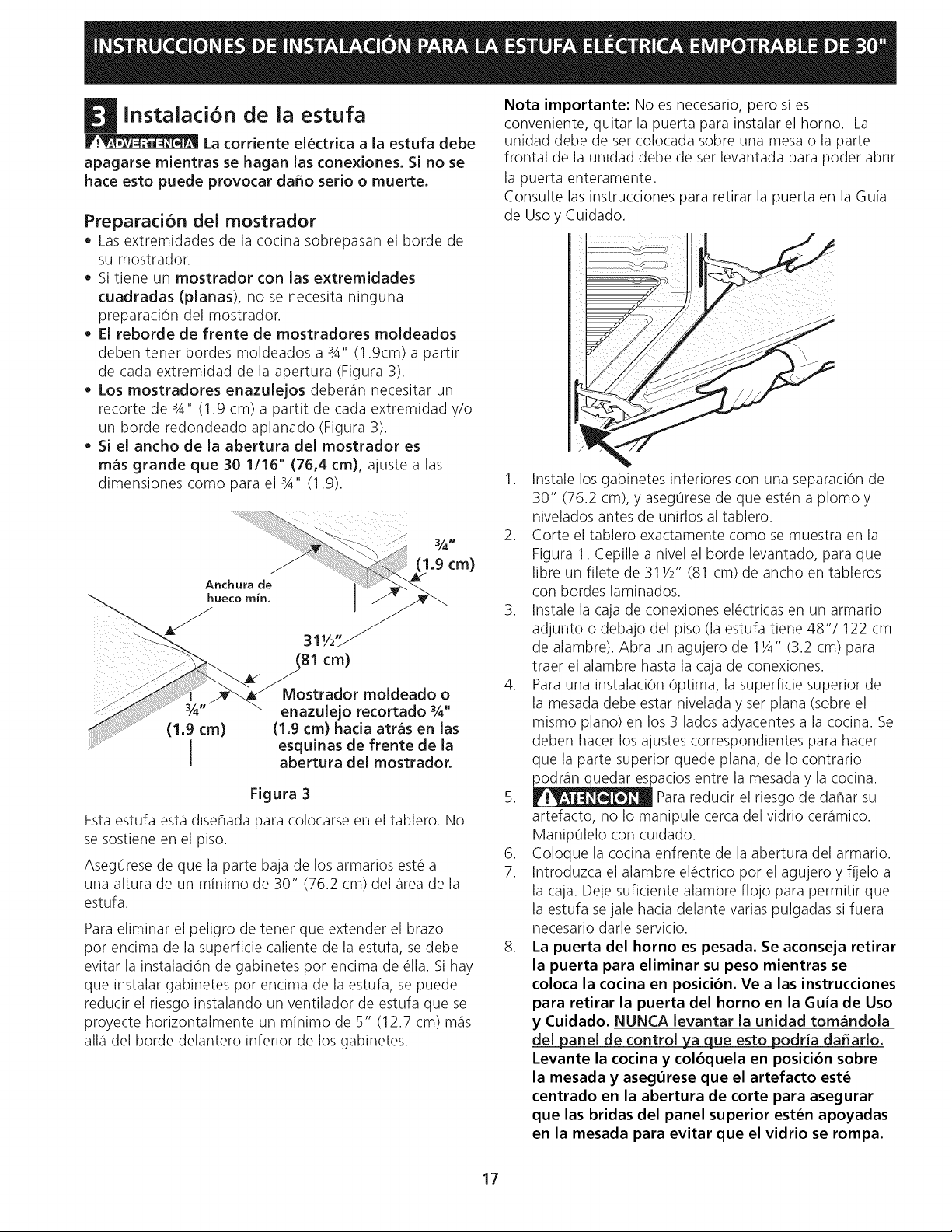
El reborde de frente de mostradores moldeados
deben tenet hordes moldeados a 3A" (1.gcm) a partir
de cada extremidad de la apertura (Figura 3).
Los mostradores enazulejos deber_in necesitar un
recorte de 3A" (1.9 cm) a partit de cada extremidad y/o
un horde redondeado aplanado (Figura 3).
Si el ancho de la abertura del mostrador es
m_s grande que 30 1/16" (76,4 cm), ajuste alas
dimensiones como para el 3A" (1.9).
Mostrador moldeado o
enazulejo recortado %"
(1.9 cm)
Esta estufa est,1disehada para colocarse en el tablero. No
se sostiene en el piso.
Aseg0rese de que la parte baja de los armarios est_ a
una altura de un minimo de 30" (76.2 cm) del _ireade la
estufa.
Para eliminar el peligro de tenet que extender el brazo
pot encima de la superficie caliente de la estufa, se debe
evitar la instalaci6n de gabinetes pot encima de @lla.Sihay
que instalar gabinetes pot encima de la estufa, se puede
reducir el riesgo instalando un ventilador de estufa que se
proyecte horizontalmente un minimo de 5" (12.7 cm) m_is
all_idel horde delantero inferior de los gabinetes.
(1.9 cm) hada atr_s en las
esquinas de frente de la
abertura del mostrador.
Figura 3
Nota importante: No es necesario, pero si es
conveniente, quitar la puerta para instalar el horno. La
unidad debe de set colocada sobre una mesa o la parte
frontal de la unidad debe de set levantada para poder abrir
la puerta enteramente.
Consulte las instrucciones para retirar la puerta en la Guia
de Uso y Cuidado.
1. Instale los gabinetes inferiores con una separaci6n de
30" (76.2 cm), y aseg0rese de que est_n a plomo y
nivelados antes de unirlos al tablero.
2. Corte el tablero exactamente como se muestra en la
Figura 1. Cepille a nivel el horde levantado, para que
libre un filete de 311/2" (81 cm) de ancho en tableros
con hordes laminados.
3. Instale la caja de conexiones el_ctricas en un armario
adjunto o debajo del piso (la estufa tiene 48"/122 cm
de alambre). Abra un agujero de 11/4"(3.2 cm) para
traer el alambre hasta la caja de conexiones.
4. Para una instalaci6n 6ptima, la superficie superior de
la mesada debe estar nivelada y set plana (sobre el
mismo piano) en los 3 lados adyacentes a la cocina. Se
deben hacer los ajustes correspondientes para hacer
que la parte superior quede plana, de Io contrario
podr_in quedar espacios entre la mesada y la cocina.
5. _ Para reducir el riesgo de dahar su
artefacto, no Io manipule cercadel vidrio cer_imico.
Manip01elo con cuidado.
6. Coloque la cocina enfrente de la abertura del armario.
7. Introduzca el alambre el_ctrico pot el agujero y fijelo a
la caja. Deje suficiente alambre flojo para permitir que
la estufa sejale hacia delante varias pulgadas si fuera
necesario darle servicio.
8. La puerta del horno es pesada. Se aconseja retirar
la puerta para elirninar su peso rnientras se
coloca la cocina en posicion. Ve a las instrucciones
para retirar la puerta del horno en la Guia de Uso
y Cuidado. NUNCA levantar la unidad tom_ndola
del panel de control ya que esto podria da#arlo.
Levante la cocina y coloquela en posicion sobre
la mesada y asegurese que el artefacto est_
centrado en la abertura de corte para asegurar
que las bridas del panel superior est_n apoyadas
en la mesada para evitar que el vidrio se rompa.
17
Page 18
D Instrucdones de instalaci6n de la
fijacion anti-vuelco
A. Instalad6n preferida anti-vuelco (Todos los
modelos)
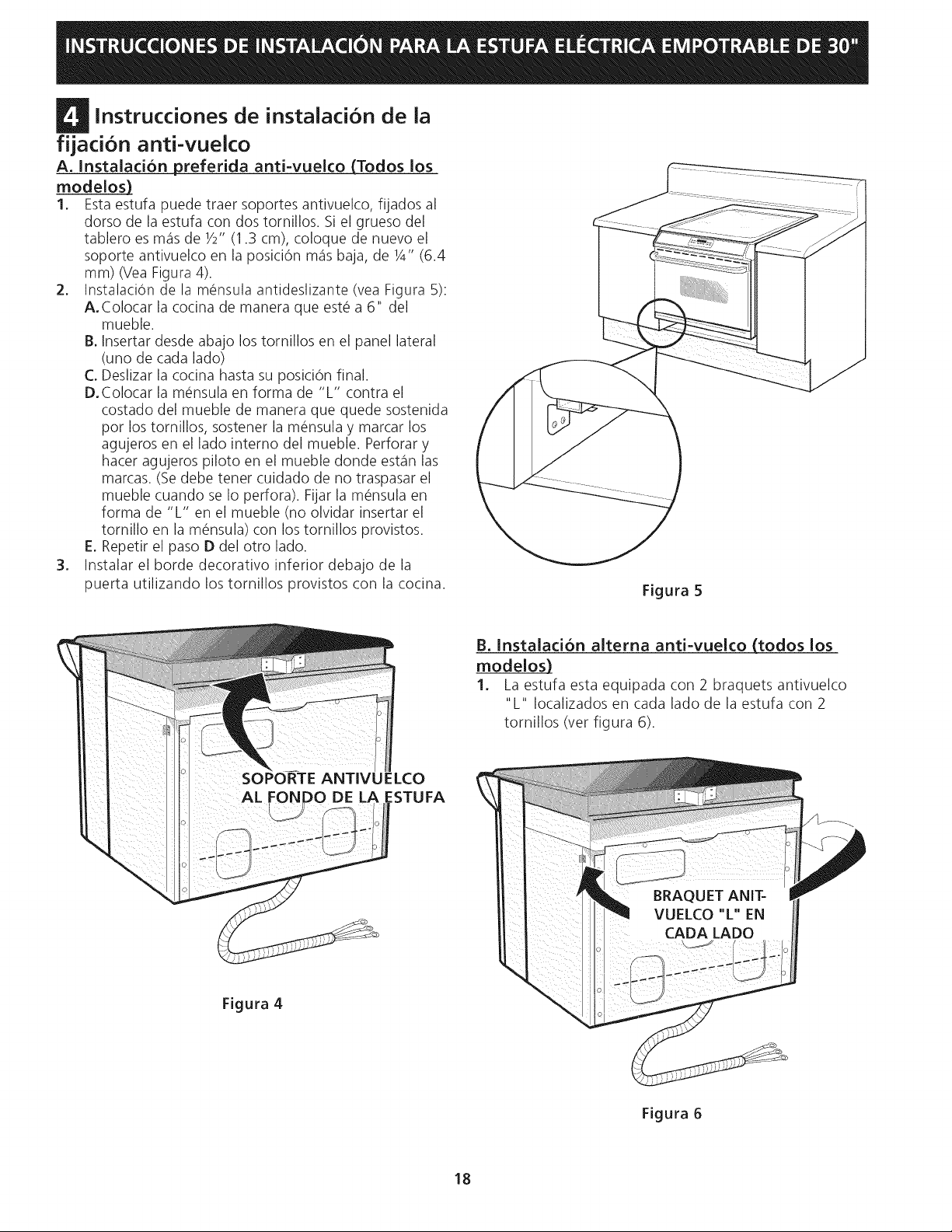
1. Esta estufa puede traer soportes antivuelco, fijados al
dorso de la estufa con dos tornillos. Si el grueso del
tablero esm_isde 1/2"(1.3 cm), coloque de nuevo el
soporte antivuelco en la posici6n m_isbaja, de 1/4"(6.4
mm) (Vea Figura 4).
2. InstalaciOn de la m_nsula antideslizante (vea Figura 5):
A.Colocar la cocina de manera que est_ a 6" del
mueble.
B. Insertar desde abajo los tomillos en el panel lateral
(uno de cada lado)
C. Deslizar la cocina hasta su posiciOn final.
D.Colocar la m_nsula en forma de "L" contra el
costado del mueble de manera que quede sostenida
por los tornillos, sostener la m_nsula y marcar los
agujeros en el lado intemo del mueble. Perforar y
hacer agujeros piloto en el mueble donde est_in las
marcas. (Se debe tener cuidado de no traspasar el
mueble cuando se Io perfora). Fijar la m_nsula en
forma de "L" en el mueble (no olvidar insertar el
tomillo en la m_nsula) con los tomillos provistos.
E. Repetir el paso D del otro lado.
3. Instalar el horde decorativo inferior debajo de la
puerta utilizando los tomillos provistos con la cocina.
Figura 5
SOPORTE ANTIVUELCO
Figura 4
B. Instalad6n alterna anti-vuelco (todos los
modelos)
1. La estufa esta equipada con 2 braquets antivuelco
"L" Iocalizados en cada lado de la estufa con 2
tomillos (ver figura 6).
:STUFA
18
Figura 6
Page 19
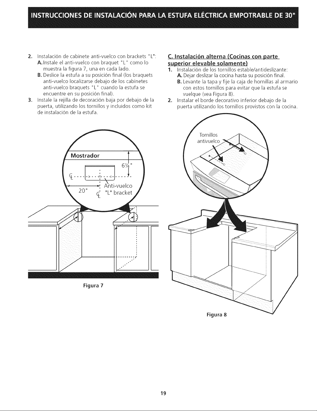
2. InstalaciOndecabineteanti-vuelcoconbrackets"L":
A.Instaleelanti-vuelcoconbraquet"L" comoIo
muestralafigura7,unaencadalado.
B.Deslicelaestufaasuposici6nfinal(losbraquets
anti-vuelcoIocalizarsedebajodeloscabinetes
anti-vuelcobraquets"L"cuandolaestufase
encuentreensuposiciOnfinal).
3. Instalelarejilladedecoraci6nbajapordebajodela
puerta,utilizandolostornillosyincluidoscomokit
deinstalaci6ndelaestufa.
C. Instalaci6n alterna (Cocinas con parte
superior elevable solamente)
1. Instalaci6n de los tornillos estable/antideslizante:
A. Dejar deslizar la cocina hasta su posici6n final,
B. Levante la tapa y fije la caja de hornillas al armario
con estos tornillos para evitar que la estufa se
vuelque (vea Figura 8).
2. Instalar el horde decorativo inferior debajo de la
puerta utilizando los tornillos provistos con la cocina.
iii_ iil i
Figura 7
Figura 8
19
Page 20
g Comprobaci6n del funcionamiento
Algunos modelos tienen controles manuales. Consulte
el Manual del Usuario y aseg0rese de que todos los
controles funcionen correctamente.
Algunos modelos est_in equipados con un control
electr6nico. Cada funci6n ha sido probada en la f_ibrica
antes del transporte. Sin embargo, sugerimos que Ud.
verifique el funcionamiento de los controles del homo
una vez m_qs.V_ase el Manual del Usuario para la
operaci6n. Siga las instrucciones para el reloj minutero,
Cocer, Asar, Convecci6n (algunos modelos) y las
funciones de limpieza (algunos modelos).
Bake/Cocer-Despu_s de poner el homo a 350°F (177°C)
para cocer, el elemento inferior debe ponerse rojo.
Broil/Asar-Cuando est_qpuesto para BROIL,el elemento
superior se debe poner rojo.
Clean/Limpieza (algunos modelos)-C uando el
homo est_qpuesto para un ciclo de auto-limpieza, el
elemento superior se pondr_i rojo durante el periodo
de precalentamiento del ciclo. Despu_s de alcanzar la
temperatura de auto-limpieza, el elemento inferior se
pondr_i rojo.
Convection/Convecci6n (algunos modelos)--Cuando
el homo se pone a CONV/BAKE los dos elementos
se encienden y se apagan alternando en un ciclo y
el ventilador se pone en marcha. Elventilador de
convecci6n se parar_i cuando se abre la puerta del homo
durante el cocido o el asado pot convecci6n.
NOTA IMPORTANTE: Un ventilador en la parte superior
y atr_is, arriba del homo (algunos modelos) provee un
enfriamiento adicional para los componentes el_ctricos
y electr6nicos del homo. Elventilador seguir_i en marcha
cuando el homo ha estado operando alas temperaturas
altas.
Ubicacion del numero de modelo y de serie
La placa con el n0mero de modelo y de serie est,1
ubicada en el horde de la puerta del homo en la posici6n
abierta.
Cuando haga pedidos de repuestos o solicite informaci6n
con respecto a su homo, est@siempre seguro de incluir
el n0mero de modelo y de serie y el n0mero o letra del
Iote de la placa de serie de su homo.
Antes de ilamar ai servicio
Lea la secciOn Lista de Control de Averias en su Manual
del Usuario. Esto le podr_i ahorrar tiempo y gastos. Esta
lista incluye ocurrencias comunes que no son el resultado
de defectos de materiales o fabricaci6n de este artefacto.
Lea la garantia y la informaci6n sobre el servicio en su
Manual del Usuario para obtener el n0mero de tel@fono
gratuito y la direcci6n del servicio. Pot favor Ilame o
escriba si tiene preguntas acerca de su homo o necesita
repuestos.
2O
 Loading...