

Page 1
ELECTRIC COOKTOP INSTALLATION INSTRUCTIONS
INSTALLATION AND SERVICE MUST BE PERFORMED BY A QUALIFIED INSTALLER.
IMPORTANT: SAVE FOR LOCAL ELECTRICAL INSPECTOR'S USE.
READ AND SAVE THESE INSTRUCTIONS FOR FUTURE REFERENCE.
WARNING
FOR YOUR SAFETY: Do not store or use gasoline or other flammable vapors and liquids in
the vicinity of this or any other appliance.
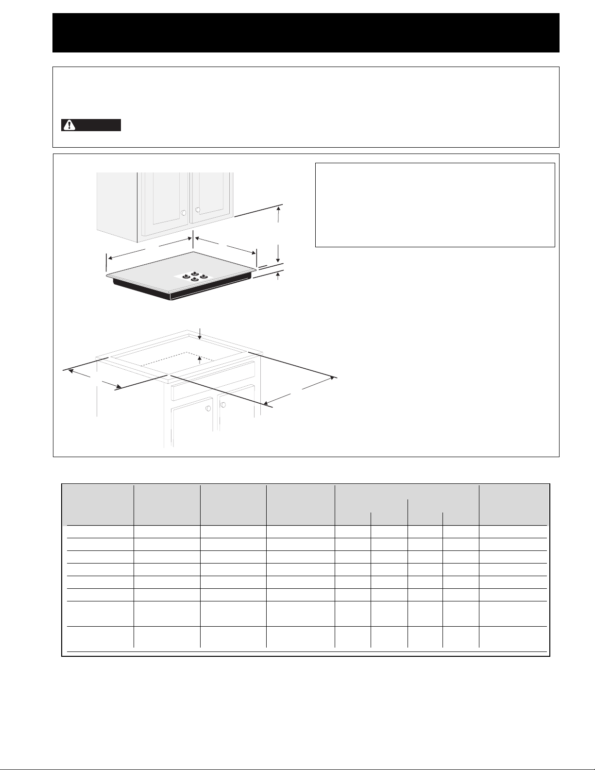
Cooktop Dimensions
A
B
Cooktop Cutout Dimensions
F
E
30" Min. *
(76.2 cm)
C
IMPORTANT INSTALLATION-INFORMATION
• All electric cooktops run off a single phase, three-wire
or four-wire cable, 240/208 volt, 60 hertz, AC only
electrical supply with ground.
• Please note minimum distances between cooktop and
adjacent and overhead cabinetry is 30" (76.2 cm).
D
* 30" (76.2 cm) min. for unprotected cabinet
24" (61 cm) min. for protected surface
Figure 1
CUTOUT DIMENSIONS
MODEL A. LENGTH B. WIDTH C. DEPTH D. LENGTH E. WIDTH F. DEPTH BELOW
3
26" Coil Elements 25
30" Ceramic-Glass 30
/
4 (65.4) 21
3
/
4 (78.1) 21
30" Coil Elements 30 (76.2) 21
1
32" Ceramic-Glass 32
32" Coil Elements 32
36" Ceramic-Glass 36
/
4 (81.9) 20
1
/
4 (81.9) 20
3
/
4 (93.3) 21
36" Coil Elements 36 (91.4) 18 (45.7) 3
9
/
16 (54.8) 3
3
/
8 (54.3) 3 (7.6) 29
1
/
2 (54.6) 3 (7.6) 26
1
/
4 (51.4) 3
1
/
4 (51.4) 3
3
/
8 (54.3) 3 (7.6) 35
1
/
2 (8.9) 25 (63.5) 25 (63.5) 20
3
/
4 (9.5) 31 (78.7) 31
3
/
4 (9.5) 31 (78.7) 31
7
/
8 (9.8) 34
(36"X18"model)
1
36" Coil Elelments 36 (91.4) 21
/
2 (54.6) 3 (7.6) 32
(36"X211/2"model)
All dimensions are in inches (cm).
Only some models are available in Canada.
* Allow 2" (5 cm) space below cooktop to clear the electric cable and allow for installation of the junction box on the wall at the
back of the cooktop.
1
MIN. MAX. MIN. MAX. COOKTOP*
5
/
8 (75.2) 29
3
/
4 (67.9) 28
7
/
8 (91.1) 36
1
/
4 (87) 34
3
/
4 (83.2) 34
1
/
7
/
8 (75.9) 20
1
/
4 (71.8) 19
1
/
4 (79.4) 19 (48.3) 19
1
/
4 (79.4) 19 (48.3) 19
1
/
8 (91.8) 20
3
/
8 (87.3) 16
1
/
4 (87) 19 (48.3) 20 (50.8) 5 (12.7)
2 (52.1) 20
1
/
4 (51.4) 20
1
/
8 (48.6) 20 (50.8) 5 (12.7)
1
/
4 (51.4) 20
5
/
8 (42.2) 16
1
/
2 (52.1) 5
1
/
2 (52.1) 5 (12.7)
1
/
4 (48.9) 5
1
/
4 (48.9) 5
1
/
2 (52) 5 (12.7)
3
/
4 (42.5) 5
1
/
2 (14)
3
/
4 (14.6)
3
/
4 (14.6)
7
/
8 (14.9)
P/N 318201410 (0201) Rev. B
English – pages 1-6
Español – pages 7-13
Français – pages 14-20
Page 2
ELECTRIC COOKTOP INSTALLATION INSTRUCTIONS
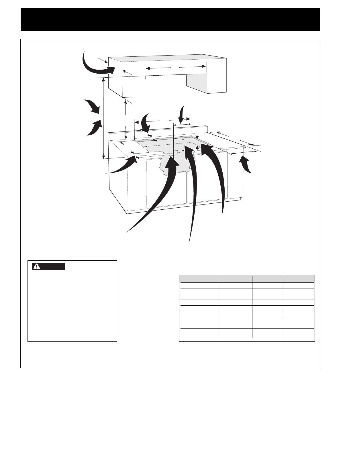
Overhead Cabinet Should Not Exceed a Maximum
Depth of 13" (33 cm)
30" (76.2 cm) Min.
Clearance Between the
Top of the Cooking
Platform and the Bottom
of an Unprotected Wood
or Metal Cabinet
24" (61 cm) Min. when
Bottom of Wood or Metal
Cabinet is Protected by Not
Less Than 1/8" Flame
Retardant Millboard Covered
With Not Less Than No. 28
MGS Sheet Steel, 0.015"
(0.4 mm) Stainless Steel,
0.024" (0.6 mm) Aluminum
or 0.020" (0.5 mm) Copper
2 1/2" (6.4 cm) Min.
From Edge of Cutout
to Front Edge of
Countertop
18"
(45.7 cm)
E
J Min.
Recommended
Distance Between
Rear Edge of Cutout
and Nearest
Combustible Surface
Above Countertop
D
A
Min.
( 25.4 cm)
10"
F
25" Min.
(63.5 cm Min.)
H Min. From Edge of
Cooktop to Nearest
Combustible Wall (Either Side
of Unit).
Approximate Location
of Junction Box
* Letters on this figure refer to chart on front
page except for G, H and J.
CAUTION
To eliminate the
risk of burns or fire by reaching
over heated surfaces, cabinet
storage space located above the
cooktop should be avoided. If
cabinet storage is provided, risk
can be reduced by installing a
range hood that projects
horizontally a minimum of 5"
(12.7 cm) beyond the bottom of
the cabinets.
Figure 2 – COUNTERTOP CUTOUT OPENING
Drawers cannot be used with
this cooktop since burner box
extends G below surface of
countertop.
12"
(30.5 cm)
MODEL GH J
26" Coil Elements 31/2 " (8.9 cm) 3" (7.6 cm) 2" (5.1 cm)
30" Ceramic-Glass 4" (10.2 cm) 71/2 " (19.1 cm) 2" (5.1 cm)
30" Coil Elements 6" (15.2 cm) 71/2 " (19.1 cm) 21/4 " (5.7 cm)
32" Ceramic-Glass 4" (10.2 cm) 71/2 " (19.1 cm) 2" (5.1 cm)
32" Coil Elements 6" (15.2 cm) 71/2 " (19.1 cm) 21/4 " (5.7 cm)
36" Ceramic-Glass 4" (10.2 cm) 71/2 " (19.1 cm) 2" (5.1 cm)
36" Coil Elements 6" (15.2 cm) 3" (7.6 cm) 3" (7.6 cm)
(36" X 18")
36" Coil Elements 6" (15.2 cm) 71/2 "(19.1 cm) 21/4 " (5.7 cm)
(36" X 211/2")
2
Page 3
ELECTRIC COOKTOP INSTALLATION INSTRUCTIONS
WARNING
Important Notes to the Installer
1. Read all instructions contained in these installation
instructions before installing the cooktop.
2. Remove all packing material before connecting the
electrical supply to the cooktop.
3. Observe all governing codes and ordinances.
4. Be sure to leave these instructions with the consumer.
Important Note to the Consumer
Keep these instructions with your owner's guide for future
reference.
IMPORTANT SAFETY
INSTRUCTIONS
• Be sure your cooktop is installed and grounded
properly by a qualified installer or service
technician.
• These cooktops must be electrically grounded in
accordance with local codes or, in their absence,
with the National Electrical Code ANSI/NFPA No.
70—latest edition in the United States, or with
CSA Standard C22.1, Canadian Electrical Code, Part
1, in Canada.
An extension cord must not be used with this
appliance. Such use may result in a fire, electrical
shock, or other personal injury.
2. The appliance should be connected to the fused
disconnect (or circuit breaker) box through flexible
armored or nonmetallic sheathed cable. The flexible
armored cable extending from this appliance should
be connected directly to the grounded junction box.
The junction box should be located as shown in
Figure 2 with as much slack as possible remaining in
the cable between the box and the appliance, so it
can be moved if servicing is ever necessary.
3. A suitable strain relief must be provided to attach
the flexible armored cable to the junction box.
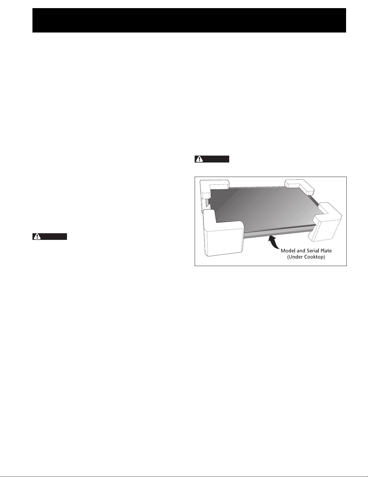
Unpacking Instructions
(Models with Ceramic-Glass Smoothtop Only)
WARNING
must be shut off while line connections are being
made. Failure to do so could result in serious injury
or death.
The electrical power to the cooktop
Provide Electrical Connection
Install the junction box under the cabinet and run 120/
240 or 120/208 Volt, AC wire from the main circuit
panel. DO NOT connect the wire to the circuit panel at
this time.
Electrical Requirements
Observe all governing codes and local ordinances.
1. A 3-wire or 4-wire single phase 120/240 or 120/208
Volt, 60 Hz AC only electrical supply is required on a
separate circuit fused on both sides of the line (timedelay fuse or circuit breaker is recommended). DO
NOT fuse neutral. The fuse size must not exceed the
circuit rating of the appliance specified on the
nameplate.
NOTE: Wire sizes and connections must conform with
the fuse size and rating of the appliance in accordance
with the National Electrical Code ANSI/NFPA No. 70–
latest edition, or with CSA Standard C22.1, Canadian
Electrical Code, Part 1, and local codes and ordinances.
Figure 3
1. Leave corner supports on cooktop until completion
of Electrical Connection.
2. Be sure the bottle of cleaner conditioner packed in
the literature bag is left where the user can find it
easily. It is important that the ceramic-glass
smoothtop be pretreated before use.
Electrical Connection
Connect the flexible armored cable that extends from
the surface unit to the junction box using a suitable
strain relief at the point the armored cable enters the
junction box. Then make the electrical connection as
follows.
Electrical ground is required on this appliance.
3
Page 4
ELECTRIC COOKTOP INSTALLATION INSTRUCTIONS
This appliance is equipped with a copper conductor
flexible cable. If connection is made to aluminum house
wiring, use only special connectors which are approved
for joining copper and aluminum wires in accordance
with the National Electrical Code and local codes and
ordinances.
This appliance is manufactured with a frame connected
green (or bare copper) ground wire.
1. If connecting to a 3-wire supply cable (U.S.A.
only): If local codes permit connection of the
frame grounding conductor to the neutral
(white) wire: (The 3-conductor cord or cable must
be replaced with a 4-conductor cord or cable where
grounding through the neutral conductor is prohibited
in new installations, mobile homes, recreational
vehicles or in other areas where local codes do not
permit neutral grounding)
Connect the green (or bare copper) wire (and the
white wire for model with warmer zone) from the
appliance cable to the supply cable ground wire
(white or bare) inside the junction box. Connect the
remaining wires inside the junction box (see Figure 4
or 5) from the power supply cable to the matching
colors of the appliance cable wires.
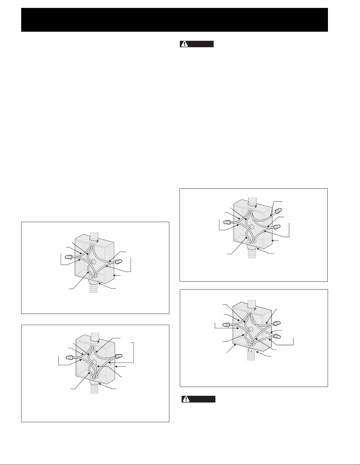
Cable from Power Supply
WARNING
Improper connection of aluminum
house wiring to copper leads can result in a short
circuit or fire. Use only connectors designed for
joining copper to aluminum, and follow the
manufacturer's recommended procedure closely.
2. If connecting to a 4-wire supply cable (also
mobile homes): The appliance frame must not be
connected to the neutral wire of the 4-wire electrical
system. Connect the appliance white wire (if a 4-wire
appliance cable is supplied) to the power supply cable
white wire. Cap the white wire from the power
supply cable if a 3-wire appliance cable is supplied.
Connect the remaining wires from the supply cable to
the matching color wires from the appliance cable
(see Figure 6 or 7). The green (or bare copper) wire
must now be used to ground the appliance in
accordance with local electrical codes. The green (or
bare copper) wire from the power supply cable is
grounded inside the house service panel.
Cable from Power Supply
Ground Wire
Red
Wires
White Wire
Black
Wires
Ground Wire
Red
Wires
Ground Wire
(Bare or Green Wire)
Cable from appliance
Figure 4 – U.S.A. Only
3-WIRE GROUNDED JUNCTION BOX
Cable from Power Supply
Ground Wire
Red
Wires
Ground Wire
(Bare or Green Wire)
Cable from appliance
Figure 5 – U.S.A. Only
Models 36" with Warmer Zone Only
3-WIRE GROUNDED JUNCTION BOX
Black
Wires
Junction Box
U.L.-Listed Conduit
Connector (or CSA listed)
Black
Wires
Junction Box
White Wire
U.L.-Listed Conduit
Connector (or CSA listed)
Junction Box
Ground Wire
(Bare or Green Wire)
Cable from appliance
U.L.-Listed Conduit
Connector (or CSA listed)
Figure 6 – 4-WIRE GROUNDED JUNCTION BOX
Cable from Power Supply
Ground Wire
Red
Wires
Ground Wire
(Bare or Green Wire)
Junction Box
Cable from appliance
White Wire
Black
Wires
White Wire
U.L.-Listed Conduit
Connector (or CSA listed)
Figure 7 – 4-WIRE GROUNDED JUNCTION BOX
Models 36" with Warmer Zone Only
WARNING
DO NOT ground to a gas supply pipe.
DO NOT connect to electrical power supply until
appliance is permanently grounded. Connect the
ground wire before turning on the power.
4
Page 5
ELECTRIC COOKTOP INSTALLATION INSTRUCTIONS
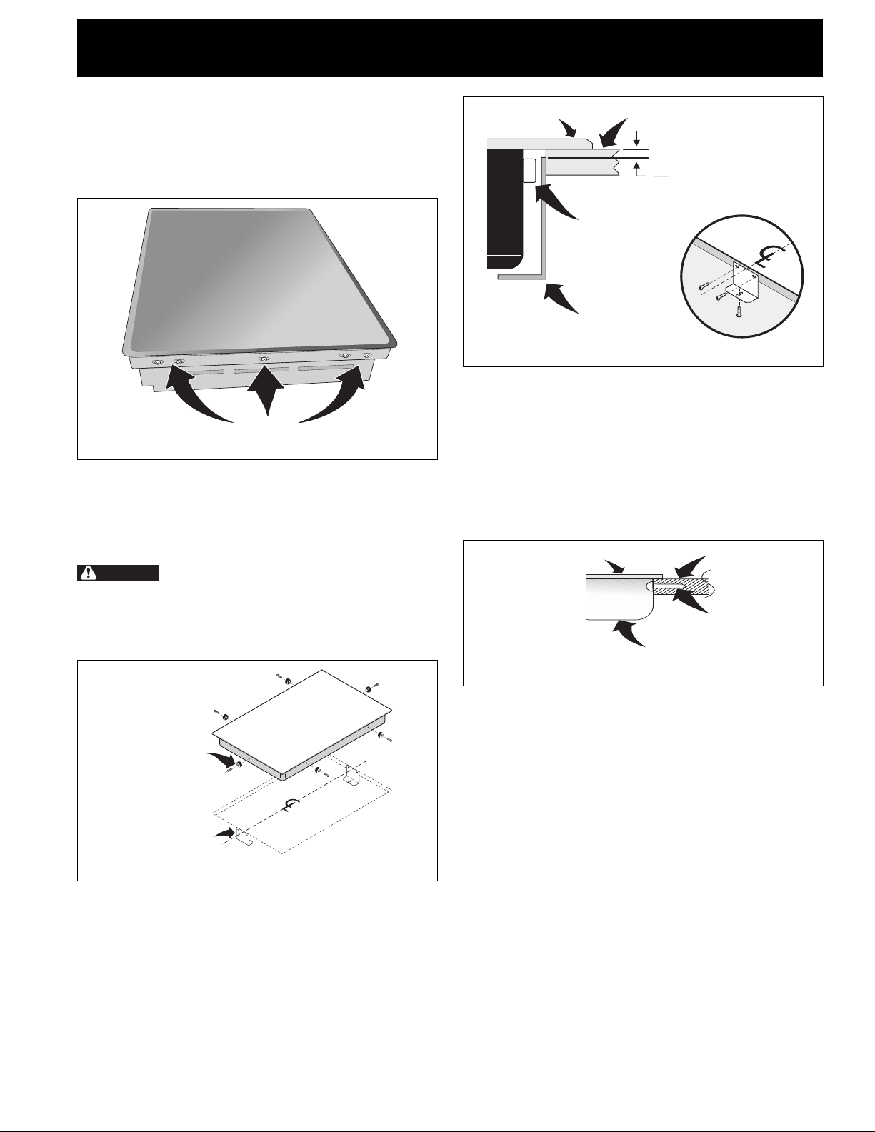
Cooktop Installation
1. All Ceramic-Glass Cooktops
Visually inspect the cooktop for damage. Also make
sure all cooktop screws are tight (see Figure 8).
SCREWS
Figure 8
Set the cooktop into the countertop cutout.
NOTE: Do not use caulking compound; cooktop
should be removable for service when needed.
WARNING
the edges of the cooktop. These spacers center the
cooktop in the space provided. The cooktop must
be centered to prevent excess heat buildup that
may result in heat damage or fire (see Figure 9).
Do not remove the nylon spacers on
COOKTOP
NYLON
SPACER
RETAINER
BRACKET
COUNTERTOP
Retainer Brackets Must Be
Installed At Lest 1/16"
(0.16 cm) BELOW
Countertop
Figure 10
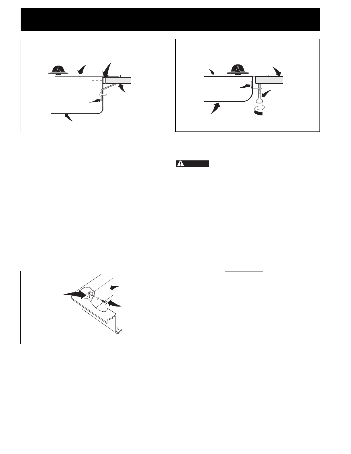
2. Models: 26" and 36" (36"X18") Coil Elements
Cooktops
Set the cooktop into the contertop cutout. Lift the
cooktop and fasten the ends of the box to the counter
with wood screws (figure 11). Lower the cooktop.
Align the knobs on the shafts and press down with
even pressure. After setting the unit into the opening,
all remaining work must be done from inside the
cabinet.
COOKTOP
BURNER BOX
COUNTERTOP
SCREW
Figure 11
6 NYLON SPACERS
POSITION BRACKETS
ON UNIT CUTOUT
CENTERLINE
2 RETAINER
BRACKETS
Figure 9
The retainer brackets MUST be installed, to meet
local codes or, in their absence, with the National
Electrical Code ANSI/NFPA No. 70—latest edition,
or with CSA Standard C22.1, Canadian Electrical
Code, Part 1 (see Figure 10).
3. Models: 32" Coil Elements Cooktops
1. Place cooktop into countertop opening and
center unit in cutout.
2. Remove all surface units and drip bowls.
3. Unit clamp down information. Once unit is
installed in counter opening, you must clamp unit
down as shown in figure 12.
4. Put back all surface units and drip bowls.
5. Make electrical connections as outlined in
"Electrical Connection" section.
5
Page 6
ELECTRIC COOKTOP INSTALLATION INSTRUCTIONS
Reach down through surface unit openings and install the four
hold down retainers with screws as shown. Be certain cooking
top is firmly retained to counter top.
COOKTOP
HOLD DOWN
RETAINER
BURNER BOX
NYLON SPACER
COUNTERTOP
Figure 12
4. Models: 30" and 36" (36"X 211/2") Coil Elements
Cooktops
- These cooktops are designed to fit various cutout
sizes. The minimum and maximum cutout openings
are shown in figure 1.
- If cooktop is to be used in new installation, use
minimum cutout dimensions in figure 1.
- Attach cooktop to cabinet using wood screws
through holes in vertical walls of burner box.
- If cooktop is to be installed as a replacement
in an existing countertop opening (not
exceeding maximum cutout dimensions as
shown in figure 1), the following steps must
be taken:
1. Insert 4 screws and installation spacers through
holes in vertical walls of burner box (see figure
13).
2. Place cooktop into countertop opening and
center unit in cutout.
BURNER BOX
SPACER
To clamp down, insert bracket with offset side of angle into slot
on each side of unit. The tumb screw should then be run thru
bracket and un against bottom of counter. Tighten until draws
down.
COOKTOP
HOLD DOWN
RETAINER
BURNER BOX
COUNTERTOP
SCREW
Figure 14
Checking Operation
Refer to the Owner's Guide for operation.
CAUTION
Do not touch cooktop glass or elements.
They may be hot enough to burn.
Model and Serial Number Location
The serial plate is located under the cooktop or in the
burner box and can be seen by lifting up the main top of
unit.
When ordering parts for or making inquires about your
cooktop, always be sure to include the model and serial
numbers and a lot number or letter from the serial plate
on your cooktop.
Before You Call for Service
Read the Avoid Service Checklist and operating
instructions in your Owner's Guide. It may save you time
and expense. The list includes common occurrences that
are not the result of defective workmanship or materials
in this appliance.
SCREW
Figure 13
3. Tighten each screw finger tight or until spacers
are snug against burner box walls.
4. Prior to tightening installation screws, exert
downward pressure on burner box to assure
flanges on burner box rest firmly on counter.
Tighten all screws evenly.
5. Unit clamp down information. Once unit is
installed in counter opening, you must clamp unit
down as shown in figure 14.
6. Make electrical connections as outlined in
"Electrical Connection" Section.
Refer to the warranty in your Owner's Guide for our
service phone number and address. Please call or write if
you have inquiries about your product and/or need to
order parts.
6
Page 7

INSTRUCCIONES PARA LA INSTALACION DE LA ESTUFA ELECTRICA
LA INSTALACION Y EL SERVICIO DEBEN SER EFECTUADOS POR UN INSTALADOR CALIFICADO.
IMPORTANTE: GUARDE ESTAS INSTRUCCIONES PARA USO DEL INSPECTOR LOCAL DE
ELECTRICIDAD.
LEA Y GUARDE ESTAS INSTRUCCIONES PARA REFERENCIA FUTURA.
PARA SU SEGURIDAD: No almanece ni utilice gasolina u otros vapores y líquidos inflamables
en la proximidad de este o de cualquier otro artefacto.
Dimensiones de la Estufa
INFORMACION IMPORTANTE PARA LA
INSTALACION
• Todas las estufas eléctricas funcionan con una
alimentación eléctrica con puesta a tierra de fase singular,
30" Min. *
(76.2 cm)
A
B
C
3 o 4 alambres, 240/208 voltios, 60 hertz y sólo AC.
• Favor de notar que las distancias mínimas entre la superficie
de la estufa y los gabinetes adyacentes y por encima son
de 30" (76.2 cm).
Dimensiones del Recortado de la Estufa
F
E
D
* 30" (76.2 cm) mín. para un gabinete desprotegido.
24" (61 cm) mín. para una superficie protegida.
Figura 1
DIMENSIONES DE RECORTADO F. PROFUNDIDAD
MODELO A. LONGITUD B. ANCHURA C. PROFUNDIDAD D. LONGITUD E. ANCHURA DEBAJO DE LA
3
26" Resistencias espirales 25
30" Vidrio-cerámica 30
/
4 (65.4) 21
3
/
4 (78.1) 21
30" Resistencias espirales 30 (76.2) 21
1
32" Vidrio-cerámica 32
32" Resistencias espirales 32
36" Vidrio-cerámica 36
/
4 (81.9) 20
1
/
4 (81.9) 20
3
/
4 (93.3) 21
9
/
16 (54.8) 3
3
/
8 (54.3) 3 (7.6) 29
1
/
2 (54.6) 3 (7.6) 26
1
/
4 (51.4) 3
1
/
4 (51.4) 3
3
/
8 (54.3) 3 (7.6) 35
36" Resistencias espirales 36 (91.4) 18 (45.7) 3
(36"X18"modelo)
1
36" Resistencias espirales 36 (91.4) 21
/
2 (54.6) 3 (7.6) 32
(36"X211/2"modelo)
1
/
2 (8.9) 25 (63.5) 25 (63.5) 20
3
/
4 (9.5) 31 (78.7) 31
3
/
4 (9.5) 31 (78.7) 31
7
/
8 (9.8) 34
MIN. MAX. MIN. MAX. ESTUDFA*
5
/
8 (75.2) 29
3
/
4 (67.9) 28
7
/
8 (91.1) 36
1
/
4 (87) 34
3
/
4 (83.2) 34
1
/
7
/
8 (75.9) 20
1
/
4 (71.8) 19
1
/
4 (79.4) 19 (48.3) 19
1
/
4 (79.4) 19 (48.3) 19
1
/
8 (91.8) 20
3
/
8 (87.3) 16
1
/
4 (87) 19 (48.3) 20 (50.8) 5 (12.7)
2 (52.1) 20
1
/
4 (51.4) 20
1
/
8 (48.6) 20 (50.8) 5 (12.7)
1
/
4 (51.4) 20
5
/
8 (42.2) 16
1
/
2 (52.1) 5
1
/
2 (52.1) 5 (12.7)
1
/
4 (48.9) 5
1
/
4 (48.9) 5
1
/
2 (52) 5 (12.7)
3
/
4 (42.5) 5
1
/
2 (14)
3
/
4 (14.6)
3
/
4 (14.6)
7
/
8 (14.9)
Todas las dimensiones se dan en pulgadas (cm).
Solamente algunos modelos están disponibles en Canadá.
* Deje 2" (5 cm) de hueco debajo de la estufa para espacio para el cable eléctrico y la instalación de la caja de empalmes en la
pared detrás de la estufa.
P/N 318201410 (0201) Rev. B
English – pages 1-6
Español – páginas 7-13
7
Français – pages 14-20
Page 8

INSTRUCCIONES PARA LA INSTALACION DE LA ESTUFA ELECTRICA
El armario superior no debe sobrepasar una
profundidad máxima de 13" (33 cm)
A
Min.
30" (76.2 cm) min. de espacio
entre la parte superior del
fogón y la parte inferior de un
armario de madera o metal sin
protección.
24" (61 cm) min. cuando la parte
inferior del armario de madera o
metal está protegida por una
placa cortafuego retardante de
llama de no menos de 1/4",
cubierta con una lámina de acero
msg no inferior al No. 28, de
acero inoxidable de 0.015",
aluminio de 0.024" o cobre de
0.020".
2 1/2" (6.4 cm) mín. desde el
borde delantero del corte hasta el
borde delantero de la parte
superior del armario
Ubicación aproximada de la caja
18"
(45.7 cm)
de empalmes
J min. distancia
recomendada entre el
borde trasero del corte y
el compartimiento de
combustible más cercano
sobre la parte superior
del armario
D
E
12"
(30.5 cm)
10"
(25.4 cm)
F
25" Min.
(63.5 cm Min.)
H min. desde el borde
del corte hasta el
compartimiento de
combustible (ambos
lados del artefacto)
Los cajones no se pueden usar con esta
estufa porque la caja de los quemadores
se extiende G por debajo de la superficie
del armario.
Para evitar
riesgos de quemaduras o
incendios al tocar superficies
calientes, se deben evitar los
armarios sobre la superficie de
los quemadores. Si existe un
armario, se pueden reducir los
riesgos instalando una campana
que se extienda horizontalmente
en un mínimo de 5" (12.7 cm)
por sobre la parte inferior de los
armarios.
Figura 2 – EL CORTE DE LA PARTE SUPERIOR DEL ARMARIO
MODELO GH J
26" Resistencias espirales 31/2 " (8.9 cm) 3" (7.6 cm) 2" (5.1 cm)
30" Vidrio-cerámica 4" (10.2 cm) 71/2 " (19.1 cm) 2" (5.1 cm)
30" Resistencias espirales 6" (15.2 cm) 71/2 " (19.1 cm) 21/4 " (5.7 cm)
32" Vidrio-cerámica 4" (10.2 cm) 71/2 " (19.1 cm) 2" (5.1 cm)
32" Resistencias espirales 6" (15.2 cm) 71/2 " (19.1 cm) 21/4 " (5.7 cm)
36" Vidrio-cerámica 4" (10.2 cm) 71/2 " (19.1 cm) 2" (5.1 cm)
36" Resistencias espirales 6" (15.2 cm) 3" (7.6 cm) 3" (7.6 cm)
(36" X 18")
36" Resistencias espirales 6" (15.2 cm) 71/2 "(19.1 cm) 21/4 " (5.7 cm)
(36" X 211/2")
8
Page 9

INSTRUCCIONES PARA LA INSTALACION DE LA ESTUFA ELECTRICA
Notas importantes para el instalador
1. Lea todas las instrucciones contenidas en este manual
antes de instalar la estufa.
2. Saque todo el material usado en el embalaje de la
estufa antes de conectar el suministro eléctrico a la
estufa.
3. Observe todos los códigos y reglamentos pertinentes.
4. Deje estas instrucciones con el consumidor.
Nota importante al consumidor
Conserve estas instrucciones y el Manual del usuario para
referencia futura.
INSTRUCCIONES
IMPORTANTES DE SEGURIDAD
• Asegúrese de que su estufa sea instalada y puesta
a tierra de forma apropiada por un instalador
calificado o por un técnico de servicio.
• Esta estufa debe ser eléctricamente puesta a tierra
de acuerdo con los códigos locales o, en su
ausencia, con el Código Eléctrico Nacional ANSI/
NFPA No. 70 – última edición en los Estados
Unidos, o el Código Eléctrico Canadiense CSA
Standard C22.1, Part 1 en Canadá.
La alimentación eléctrica a la estufa
debería apagarse mientras se hacen las conexiones
de línea. El no harcelo podría resultar en daños
serios o la muerte.
enchufar este electrodomestico. Esto podría resultar
en un incendio, un choque eléctrico u otro tipo de
daño personal.
2. Este electrodomestico debe conectarse a la caja de
fusibles (o de cortacircuitos), por medio de un cable
blindado flexible o un cable con forro no metálico. El
cable blindado flexible que va desde el
electrodomestico debe de estar conectado
directamente a la caja de empalme. La caja de
empalme debe de estar localizada en el lugar que se
indica en la Figura 2, dejando tanto exceso de cable
como sea posible entre la caja y el electrodomestico,
de forma que así el electrodomestico se pueda mover
fácilmente, si fuera necesario para hacer una
reparación.
3. Se debe de usar un conectador que reduzca la tirantez
de una forma adecuada para unir el cable blindado
flexible a la caja de empalme.
Instrucciones de desembalaje
(Solamente para modelos con superficies de vidriocerámica)
No se debe usar una alargadora para
Provea conexión eléctrica
Instale la caja de empalmes debajo del armario y provea
un cable de 120/240 o 120/208 Voltios, AC al panel de
circuitos del aparato. NO conecte la cable al panel de
circuitos en este momento.
Requisitos eléctricos
Cumpla con todos los códigos en vigor y todos los
reglamentos locales.
1. Para el suministro eléctrico solamente se necesita
corriente con frecuencia de 60 Hz AC y fase única de
120/240 o 120/208 voltios suministrada por cable de 3
o de 4 alambres en un circuito separado con fusibles
en ambos lados de la línea (se recomienda un fusible
de tiempo retardado o un cortacircuitos). NO ponga un
fusible en el hilo neutro. El tamaño del fusible no tiene
que exceder la capacidad del circuito necesario para el
electrodomestico y la cual se especifica en la placa.
NOTA: El tamaño de los cables y de las conexiones debe
de estar en conformidad con el tamaño del fusible y con la
capacidad del electrodomestico y de acuerdo con el Código
Eléctrico Nacional ANSI/NFPA No. 70 - última edición, o el
Código Eléctrico Canadiense CSA Standard C22.1, Part 1,
y los códigos y reglamentos locales.
Placa con los numeros de modelo y serie
(debajo de la cubierta)
Figura 3
1. Deje los soportes de las esquinas en la estufa hasta
la terminación de la Conexión Electrica.
2. Asegúrese que la botella de limpiador ubicada en la
empaquete de literatura esta situada en un lugar
donde puede encontrarse fácilmente. Es importante
que la parte lisa en cerámico vidriado sea tratada
antes de la utilización.
Conexión Eléctrica
Conecte el cable blindado flexible que se extiende desde
la superficie del artefacto hasta la caja de empalmes
utilizando una grapa de alivio de tensión adecuada en el
punto en que el cable blindado entra en la caja de
empalmes. Realizar luego la conexión eléctrica de la
siguiente manera:
9
Page 10

INSTRUCCIONES PARA LA INSTALACION DE LA ESTUFA ELECTRICA
En este electrodomestico se necesita un cable de
puesta a tierra.
Este electrodoméstico viene equipado con un cable de
conexión de cobre. Si esto tuviera que conectarse a los
cables de aluminio de una casa, use solamente los
conectores especiales aprobados para empalmes de cobre
y aluminio, de acuerdo con el Código Eléctrico Nacional y
los reglamentos y códigos locales.
Este electrodoméstico se fabrica con un alambre de
puesta a tierra verde (o de cobre sin forro) conectado
con el marco.
1. Si se conecta a un cable de suministro de tres
alambres (solamente en los Estados Unidos): Si
los códigos locales permiten la conexión del
conductor de puesta a tierra del marco al alembre
neutral (blanco): (Un cordón flexible o cable de 3
conductores debe de ser reemplazado con un cordón
flexible o cable de 4 conductores donde la conexión
del conductor a tierra al neutro esta prohibida en las
nuevas instalaciones, las casas sobre ruedas, los
vehículos de recreación o otras áreas donde los códigos
locales no permiten la conexión a tierra al neutro.)
Conecte el alambre verde (o el alambre de cobre sin
forro) (y alambre blanco para modelo 36" con superficies de vidrio-cerámica y zona hornilla) del cable del
electrodoméstico al cable de puesta a tierra (blanco o
sin forro) dentro de la caja de empalmes. Conecte los
otros alambres que están dentro de la caja de
empalmes (Figura 4 o 5), y que vienen desde el cable
de suministro, a los alambres del cable del aparato que
tienen colores correspondientes.
Cable desde el suministro de energía
Alambre desnudo
Alambres
rojos
Alambres
negros
Cable desde el suministro de energía
Alambre desnudo
Alambres
rojos
Alambre verde o desnudo
Cable de la estufa
Alambres
negros
Caja el empalmes
Alambre blanco
Conductor de unión
listado-UL (o CSA)
Figura 5 – Solamente en los Estados Unidos
Solamente para modelo 36" y zona hornilla
CAJA DE EMPALMES DE 3 ALAMBRES
PUESTA A TIERRA
Una conexión incorrecta del
alambrado de aluminio con los conductores de cobre
puede resultar en un cortacircuito o incendio. Use
solamente los conectores diseñados para juntar el
cobre con el aluminio y siga exactamente el
procedimiento recomendado por el fabricante.
2. Si se conecta a un cable de suministro de cuatro
alambres: La marca del aparato no debe conectarse al
alambre neutral del sistema eléctrico de cuatro
alambres. Conecte el alambre blanco del cable del
aparato (si tiene un cable de 4 alambres) al alambre
blanco del cable de suministo de energía. Ponga un
aislador en el alambre blanco del cable de suministro si
el aparato tiene un cable de sólo 3 alambres. Conecte
los alambres del cable de suministro a los alambres de
colores correspondientes del cable del aparato (Figura
6 o 7). El alambre verde (o sin forro) debe de usarse
ahora para poner a tierra del electrodomestico de
acuerdo con los códigos eléctricos locales. El alambre
verde (o el alambre de cobre sin forro) que viene desde
el cable de suministro de energía, está puesto a tierra
dentro del panel de servicio de la casa.
Caja de empalmes
Alambre verde o desnudo
Cable de la estufa
Conductor de unión
listado-UL (o CSA)
Figura 4 – Solamente en los Estados Unidos
CAJA DE EMPALMES DE 3 ALAMBRES
PUESTA A TIERRA
Alambre desnudo
Alambres
Alambre verde o desnudo
Figura 6 – CAJA DE EMPALME DE 4 ALAMBRES
10
Cable desde el suministro de energía
Alambre blanco
rojos
Cable de la estufa
Alambres
negros
Caja de empalmes
Conductor de unión
listado-UL (o CSA)
PUESTA A TIERRA
Page 11

INSTRUCCIONES PARA LA INSTALACION DE LA ESTUFA ELECTRICA
Cable desde el suministro de energía
Alambre desnudo
Alambres
rojos
Alambre verde o denudo
Caja de empalmes
Cable de la estufa
Alambre blanco
Alambres
negros
Alambre blanco
Conductor de unión
listado-UL (o CSA)
Figura 7 – CAJA DE EMPALME DE 4 ALAMBRES
PUESTA A TIERRA
Solamente para modelo 36" y zona hornilla
NO conecte el alambre puesto a tierra
a una tubería de suministro de gas. NO conecte el
suministro de energía eléctrica hasta que el
electrodomestico haya sido permanentemente puesto
a tierra. Conecte el alambre de puesto a tierra antes
de enchufar por primera vez el electrodomestico.
Instalación de la estufa
1. Modelos con superficies de Vidiro-cerámica
Visualmente inspecciones la estufa para daños.
Verifique además que todos los tornillos de la estufa
estén bien ajustados (Figura 8).
No quite los espaciadores de nilón
en los bordes de la estufa. Estos espaciadores
mantienen la estufa en el centro del espacio
provisto. La estufa debe estar centrado para evitar
una acumulación excesiva de calor que puede
resultar en daños por calor o incendio (Figura 9).
6 ESPACIADORES
DE NILÓN
2 MÉNSULAS DE
SOSTENIMIENTO
Figura 9
Las ménsulas de sostenimiento TIENEN QUE
instalarse, a satisfacción de los códigos locales o,
en su ausencia, con el Código Eléctrico Nacional
ANSI/NFPA No. 70--última edición, o con la Norma
CSA C22.1, Código Eléctrico Canadiense, Parte 1
(Figura 10).
ESTUFA
SUPERFICIE DEL
ARMARIO
Ménsulas de sostenimiento
tienen que instalarse al
menos 1/16" (0.16 cm)
BEBAJO del armario.
TORNILLOS
Figura 8
Fije la estufa en el recortado del armario.
NOTA: No utilice compuesto de retaque; la estufa
debe poder retirarse para las reparaciones cuando sea
necesario.
ESPACIADOR
DE NILON
MENSULA DE
SONSTENIMIENTO
Figura 10
2. Modelos: 26" y 36" (36"X18") con resistencias
espirales
Fije la estufa en el recortado del armario. Levante la
plancha de cocinar y fije ls extremidades de la caja al
mostrador con clavos de rosca (figura 11). Baje la
plancha de cocinar. Alinee los botónes sobre los ejes y
apriete en línea recta con igual presión. Después de
insertar la plancha de cocinar dentro de la abertura,
toda instalación restante debe realizarse al interior del
armario.
11
Page 12

INSTRUCCIONES PARA LA INSTALACION DE LA ESTUFA ELECTRICA
PLANCHA DE COCINAR
CAJA
MOSTRADOR
TORNILLO
Figura 11
3. Modelos: 32" con resistencias espirales
1.Ubique la plancha de cocinar en la abertura del
mostrador y centre el electrodoméstico en el
hueco.
2.Retire todas las unidades de superficie y las
graseras.
3.Informaciones para fijar el electrodoméstico. Una
vez que el electrodoméstico esta instalado en la
abertura del mostrador, debe de fijarlo como se
indicada en la figura 12.
4.Vuelva a poner todas las unidades de superficie y
las graseras.
5.Haga las conexiónes eléctricas como se indicada
en la parte "Conexión eléctrica".
Pase a través los orificios de superficie del electrodoméstico y
instale las 4 fijaciones con los tornillos como se muestra.
Asegúrese que la parte superior de la plancha de cocinar esta
solidamente asegurada al mostrador.
PLANCHA DE COCINAR
MOSTRADOR
FIJACIÓN PARA SUJETAR
ESPACIADOR
DE NILON
CAJA
Figura 12
4.Modelos: 30" y 36" (36 X 21 1/2") con
resistencias espirales
- La plancha para cocinar está diseñada para ajustarse
a varios tamaños de cortes. El tamaño mínimo y
máximo de la abertura se muestran an la figura 1.
- Si la plancha de cocinar va a ser usada en una
instalación nueva, use las dimensiones mínimas que
se muestran en la figura 1.
- Fije la plancha de cocinar a la mesa usando tornillos
para madera a travez de los huecos de las paredes
verticales de la base rectangular.
- Si la plancha de cocinar va a ser instalada en
una abertura existente (que no exceda las
dimensiones máximas indicadas en la figura 1),
deben seguirse los siguientes pasos:
1. Inserte 4 tornillos y espaciadores de instalación a
travez da las perforaciones en las paredes
vericales de la base rectangular como se muestra
en la figura 13.
CAJA
ESPACIADOR
TORNILLO
Figura 13
2.Coloque y centre la plancha de cocinar entre la
abertura de la mesa.
3.Apriete cada tornillo hasta que ajuste o hasta que
los espaciadores ajusten contra las paredes de la
base rectangular.
4.Antes de apretar los tornillos de instala ción,
presiones hacia abajo la base rectangular hasta
asegurar que las pestañas de la base estén
apoyadas firmemente.
5.Informacion para sujetar el aparato. Una vez que
el aparato está instalado en la apertura del
mostrador, se tiene que sujetar como se va a
indicar en la figura 14.
Para ajustar el aparato, inserte el soporte, con el lado desviado,
en la ranura en cada lodo del aparato. El tornillo que se puede
girar con los dedos debe entonces de pasar a través del soporte
y hasta la parte de abajo del mostrador. Apriételo hasta que el
aparato se quede ajustado.
PLANCHA DE
COCINAR
FIJACIÓN PARA
SUJETAR
MOSTRADOR
TORNILLO
12
CAJA
Figura 14
6.Haga las conexiónes eléctricas come se muestra
en la sección "Conexión eléctrica".
Page 13

INSTRUCCIONES PARA LA INSTALACION DE LA ESTUFA ELECTRICA
Revisión de operación
Consulte el Manual del Usuario para las instrucciones de
funcionamiento.
No toque el cristal o los elementos
de la estufa. Puede que estén lo suficiente calientes
para quemar.
Ubicación del número de modelo y de serie
La placa con el número de modelo y de serie está
ubicada en el fondo de la estufa o en la base
rectangular del quemador y puede verse al levantar la
cubierta de la unidad.
Cuando haga pedidos de repuestos o solicite información
con respecto a su estufa, esté siempre segro de incluir el
número de modelo y de serie y el número o letra del
lote de la placa de serie de su horno.
Antes de llamar al servicio
Lea la sección Lista de Control de Averías en su Manual
del Usuario. Esto le podrá ahorrar tiempo y gastos. Esta
lista incluye ocurrencias comunes que no son el resultado
de defectos de materiales o fabricación de este
artefacto.
Lea la garantía y la información sobre el servicio en su
Manual del Usuario para obtener el número de teléfono
y la dirreción del servicio. Por favor llame o escriba si
tiene preguntas acerca de su estufa o necesita
repuestos.
13
Page 14

INSTRUCTIONS D'INSTALLATION POUR PLAQUE DE CUISSON ÉLECTRIQUE
UN INSTALLATEUR QUALIFIÉ DOIT EFFECTUER L’INSTALLATION ET LE SERVICE.
IMPORTANT: CONSERVEZ CES INSTRUCTIONS POUR LES INSPECTEURS LOCAUX.
LISEZ CES INSTRUCTIONS ET CONSERVEZ-LES POUR RÉFÉRENCES ULTÉRIEURES.
POUR VOTRE SÉCURITÉ: N’entreposez et n’utilisez pas d’essence ou d’autres produits
inflammables à proximité de cet appareil ou de tout autre appareil.
Dimensions de la plaque de cuisson
INSTRUCTIONS DE SÉCURITE IMPORTANTES
• Toutes les plaques de cuisson électriques
fonctionnent avec un câble à 3 ou 4 fils monophasé
de 240/208 volts, 60 hertz CA mise à la terre
30" Min. *
(76.2 cm)
A
B
C
seulement.
• Veuillez prendre note que la distance minimale entre
la plaque de cuisson et les armoires adjacentes et en
surplomb est de 30" (76.2 cm).
Dimensions de découpage pour la plaque de cuisson
F
E
D
* Minimum de 30" (76.2 cm) pour armoire non protégée.
Minimum de 24" (61 cm) pour surface protégée.
Figure 1
DIMENSIONS DE DÉCOUPAGE F. PROFONDEUR
MODÈLE A. LONGUEUR B. LARGEUR C. PROFONDEUR D. LONGUEUR E. LARGEUR SOUS LA PLAQUE
3
26" Élements spiraux 25
30" Vitrocéramique 30
/
4 (65.4) 21
3
/
4 (78.1) 21
30" Élements spiraux 30 (76.2) 21
1
32" Vitrocéramique 32
32" Élements spiraux 32
36" Vitrocéramique 36
/
4 (81.9) 20
1
/
4 (81.9) 20
3
/
4 (93.3) 21
9
/
16 (54.8) 3
3
/
8 (54.3) 3 (7.6) 29
1
/
2 (54.6) 3 (7.6) 26
1
/
4 (51.4) 3
1
/
4 (51.4) 3
3
/
8 (54.3) 3 (7.6) 35
36" Élements spiraux 36 (91.4) 18 (45.7) 3
(modèle 36"X18")
1
36" Élements spiraux 36 (91.4) 21
/
2 (54.6) 3 (7.6) 32
(modèle 36"X211/2")
1
/
2 (8.9) 25 (63.5) 25 (63.5) 20
3
/
4 (9.5) 31 (78.7) 31
3
/
4 (9.5) 31 (78.7) 31
7
/
8 (9.8) 34
MIN. MAX. MIN. MAX. DE CUISSON*
5
/
8 (75.2) 29
3
/
4 (67.9) 28
7
/
8 (91.1) 36
1
/
4 (87) 34
3
/
4 (83.2) 34
1
/
7
/
8 (75.9) 20
1
/
4 (71.8) 19
1
/
4 (79.4) 19 (48.3) 19
1
/
4 (79.4) 19 (48.3) 19
1
/
8 (91.8) 20
3
/
8 (87.3) 16
1
/
4 (87) 19 (48.3) 20 (50.8) 5 (12.7)
2 (52.1) 20
1
/
4 (51.4) 20
1
/
8 (48.6) 20 (50.8) 5 (12.7)
1
/
4 (51.4) 20
5
/
8 (42.2) 16
1
/
2 (52.1) 5
1
/
2 (52.1) 5 (12.7)
1
/
4 (48.9) 5
1
/
4 (48.9) 5
1
/
2 (52) 5 (12.7)
3
/
4 (42.5) 5
1
/
2 (14)
3
/
4 (14.6)
3
/
4 (14.6)
7
/
8 (14.9)
Toutes les dimensions sont en pouces (cm).
Seulement certains modèles sont disponsibles au Canada.
* Laissez un espace de 2" (5 cm) au-dessous de la plaque de cuisson pour dégager le câble et faciliter l'installation de la boîte de
jonction sur le mur à l'arrière de la plaque de cuisson.
P/N 318201410 (0201) Rev. B
English – pages 1-6
14
Español – pages 7-13
Français – pages 14-20
Page 15

INSTRUCTIONS D'INSTALLATION POUR PLAQUE DE CUISSON ÉLECTRIQUE
L’armoire supérieure ne doit pas excéder une profondeur
Dégagement minimum de 30"
(76.2 cm) entre le haut de la
surface de cuisson et la base de
l’armoire en bois ou en métal
Minimum de 24" (61 cm) lorsque la
base de l’armoire en bois ou en
métal est protégée par un
celloderme retardateur de
flammes d’un minimum de 1/8"
recouvert d’une feuille de métal
MSG No 28, d’acier inoxydable
d’un minimum de 0,015 (0.4 mm),
d’aluminium de 0,024 (0.6 mm) ou
de cuivre de 0,020 (0.5 mm).
maximale de 13" (33 cm).
non protégée.
18"
(45.7 cm)
Minimum de 2-1/2" (6.4 cm)
du rebord de découpage au
rebord avant du dessus de
comptoir.
Distance minimum de J
recommandée entre le
rebord arrière de
découpage et le mur
en matériel combus-
tible le plus proche du
dessus de comptoir.
D
E
A
Min.
(25.4 cm)
10"
F
25"
(63.5 cm)
Minimum de H du rebord
de la plaque de cuisson au
mur en matériel inflam-
mable le plus proche (de
chaque côté de l’appareil).
Emplacement approximatif de
la boîte de jonction.
* Les lettres sur cette figure réfèrent aux valeurs du tableau de la
page précédente excepté pour G, H et J.
Pour
éliminer les risques de brûlures ou
de feu en allongeant le bras
au-dessus des surfaces de cuisson
chaudes, évitez d’installer des
armoires au-dessus de la plaque
de cuisson. Si vous devez en
installer, il est possible de réduire
le risque en plaçant une hotte
pour cuisinière qui excède
horizontalement d’un minimum
de 5" (12.7 cm) la base de
l’armoire.
Figure 2 – OUVERTURE DU DÉCOUPAGE DE DESSUS DU COMPTOIR
Cette plaque de cuisson ne
permet pas d’utiliser de tiroirs
sous-jacents car la boîte de
brûleur occupe G au-dessous de
12"
(30.5 cm)
MODEL GH J
26" Élements spiraux 31/2 " (8.9 cm) 3" (7.6 cm) 2" (5.1 cm)
30" Vitrocéramique 4" (10.2 cm) 71/2" (19.1 cm) 2" (5.1 cm)
30" Élements spiraux 6" (15.2 cm) 71/2" (19.1 cm) 21/4 " (5.7 cm)
32" Vitrocéramique 4" (10.2 cm) 71/2" (19.1 cm) 2" (5.1 cm)
32" Élements spiraux 6" (15.2 cm) 71/2" (19.1 cm) 21/4 " (5.7 cm)
36" Vitrocéramique 4" (10.2 cm) 71/2" (19.1 cm) 2" (5.1 cm)
36" Élements spiraux 6" (15.2 cm) 3" (7.6 cm) 3" (7.6 cm)
(36" X 18")
36" Élements spiraux 6" (15.2 cm) 71/2 "(19.1 cm) 21/4 " (5.7 cm)
(36" X 211/2")
la surface du dessus de comptoir.
15
Page 16

INSTRUCTIONS D'INSTALLATION POUR PLAQUE DE CUISSON ÉLECTRIQUE
Installateur
1. Lisez toutes ces instructions avant de procéder à
l’installation de la plaque de cuisson.
2. Enlevez tout le matériel d’emballage avant de procéder
au raccordement électrique.
3. Observez tous les codes et règlements applicables.
4. Assurez-vous de laisser ces instructions au
consommateur.
Consommateur
Conservez ces instructions avec votre Guide de l’utilisateur
pour références futures.
DIRECTIVES IMPORTANTES
DE SÉCURITÉ
• Assurez-vous que votre plaque de cuisson est
installée et mise à la terre correctement par un
installateur ou une technicien de service qualifié.
• Cette plaque de cuisson doit être mise à la terre
conformément aux codes locaux d’électricité ou, en
leurs absences, en conformité avec le National
Electrical Code ANSI/NFPA No. 70, dernière édition
aux Etats Unis, ou avec la norme ACNOR C22.1,
Partie 1 au Canada.
N’utilisez pas de rallonge
électrique avec cette appareil. Son utilisation peut
causer un feu, un choc électrique ou des blessures
corporelles.
2. Il faut brancher l’appareil au panneau de distribution
en utilisant des câbles flexibles à gaine métallique ou
non métallique. On doit brancher directement à la
boîte de jonction le câble gainé flexible de l’appareil.
Il faut installer la boîte de jonction tel qu’illustré à la
Figure 2 en laissant autant de lâche que possible dans
le câble entre la boîte et l’appareil, pour en faciliter le
déplacement si l’entretien s’avère nécessaire.
3. Une longueur de câble suffisante doit être prévue pour
permettre une connexion du câble gainé flexible à la
boîte de jonction.
Instructions de déballage
(Modèles vitrocéramiques seulement)
Il faut couper l’alimentation
électrique durant le branchement des connexions
électriques. A défaut de ce faire il peut en résulter
des blessures graves ou la mort.
Connexion électrique
Installez la boîte de jonction sous l'armoire et installez
un câble de 120/240 ou 120/208 Volts, AC au panneau
de distribution à la plaque de cuisson. Ne branchez pas
encore le câble au panneau de circuits.
Exigences électriques
Observez tous les règlements et les codes locaux
applicables.
1. Un câble électrique à 3 ou 4 fils de 120/240 ou 120/
208 Volts monophasé, 60 Hz CA est requis sur un
circuit séparé muni d’un fusible sur chaque fil
conducteur (fusible temporisé ou disjoncteur
recommandé). NE RELIEZ pas de fusible au neutre. La
capacité du fusible ne doit pas excéder la capacité
nominale du circuit de l’appareil spécifiée sur la
plaque signalétique.
NOTE: Le calibre des fils et leurs connexions doivent être
conformes à la capacité des fusibles et à la capacité
nominale de l’appareil, selon le National Electrical Code
ANSI/NFPA No. 70, dernière édition, ou avec la norme
ACNOR C22,1, Partie 1, du Code canadien d’électricité et
les codes et les règlements locaux.
Numéro de modèle et plaque signalétique
(sous la plaque de cuisson)
Figure 3
1. N’enlevez pas les coins mousse d’expédition de la
plaque de cuisson avant d’avoir terminé la connexion
électrique.
2. Assurez-vous de laisser à vue d’oeil la bouteille de
nettoyeur conditionneur qui se trouve dans l'enveloppe
de littérature. Il est important que la surface
vitrocéramique lisse soit prétraitée avant d’être utilisée.
Connexions électriques
Branchez le câble flexible armé de l’appareil à la boîte de
jonction à l’aide d’une bague anti-traction appropriée à
l’endroit où le câble armé pénètre dans la boîte de
jonction. Procédez alors comme suit avec la connexion
électrique.
La mise à la terre de cet appareil est obligatoire.
16
Page 17

INSTRUCTIONS D'INSTALLATION POUR PLAQUE DE CUISSON ÉLECTRIQUE
Cet appareil est muni d’un câble conducteur flexible avec
fils en cuivre. Si la connexion est faite à un filage
résidentiel en aluminium, utilisez seulement des
connecteurs spéciaux approuvés pour le raccord de fils en
cuivre et à des fils en aluminium conformément au code
national d'électricité et aux codes et ordonnances locaux.
Cet appareil est fabriqué avec un câble d’alimentation
possédant un fil de mise à la terre vert (ou de cuivre
dénudé) relié au châssis.
1. Pour une connexion à un cable d'alimentation à
trois fils (États-Unis seulement): Si les codes
locaux permettent la connexion du fil de mise à
la terre du châssis au neutre (blanc): (Le cordon ou
câble d'alimentation à 3-conducteurs doit être
remplacé par un cordon ou un câble à 4-conducteurs
où la mise à la terre du châssis au fil blanc est
interdite, soit dans les nouvelles installations, les
maisons mobiles, les véhicules récréatifs ou à d'autres
endroits où les codes locaux interdisent la mise à la
terre au moyen d'un conducteur neutre.)
Raccordez le fil vert (ou de cuivre dénudé) (et le fil
blanc pour le modèle 36" avec zone réchaud) du
câble de l'appareil au fil de mise à la terre du câble
d’alimentation (blanc ou dénudé) à l'intérieur de la
boîte de jonction. Raccordez les autres fils à l'intérieur
de la boîte de jonction (voir figure 4 ou 5) du câble
d’alimentation à ceux du câble de l'appareil en
joignant les fils de même couleur.
Câble d'alimentation
Fil dénudé
Fils
rouges
Fils
noirs
La connexion inappropriée d'un circuit
résidentiel en aluminium à des fils en cuivre peut
entraîner un court-circuit ou un feu. N’utilisez que
des connecteurs conçus pour joindre des fils en
cuivre à ceux en aluminium, en suivant bien
attentivement les directives recommandées par le
fabricant.
2. Pour une connexion à un cable d'alimentation à
quatre fils: Raccordez le fil blanc du câble de
l'appareil (si le câble fourni avec l'appareil comprend
4 fils) au fil blanc du câble d'alimentation. Protégez
l'extrémité exposée du fil blanc du câble
d'alimentation avec un marette si un câble à 3 fils est
fourni avec l'appareil. Raccordez les fils du câble
d’alimentation avec les fils de couleur identique du
câble de l'appareil (voir figure 6 ou 7). Le fil vert (ou
dénudé) de l'appareil doit être utilisé pour la mise à la
terre en accord avec les normes électriques locales
applicables. Le fil vert (ou de cuivre dénudé) du câble
d'alimentation est mis à la terre à l'intérieur de la
boîte d'entrée électrique de la maison.
Câble d'alimentation
Fil dénudé
Fils
rouges
Fil dénudé ou vert
Câble de l'appareil
Fil blanc
Fils
noirs
Boîte de jonction
Connecteur homologuéU.L. (ou ACNOR)
Figure 6 – BOÎTE DE JONCTION À 4 FILS
MISE A LA TERRE
Boîte de jonction
Fil dénudé ou vert
Câble de l'appareil
Connecteur homologuéU.L. (ou ACNOR)
Figure 4 – É.-U. A. Seulement
BOÎTE DE JONCTION A 3 FILS -MISE A LA TERRE
Câble d'alimentation
Fil dénudé
Fils
rouges
Fil dénudé ou vert
Câble de l'appareil
Fils
noirs
Boîte de jonction
Fil blanc
Connecteur homologuéU.L.(ou ACNOR)
Figure 5 – É.-U. A. Seulement
Modèle 36" avec zone réchaud seulement
BOÎTE DE JONCTION A 3 FILS -MISE A LA TERRE
Câble d'alimentation
Fil dénudé
Fils
rouges
Fil dénudé ou vert
Boîte de jonction
Câble de l'appareil
Fil blanc
Fils
noirs
Fil blanc
Connecteur homologuéU.L. (ou ACNOR)
Figure 7 – BOÎTE DE JONCTION À 4 FILS
MISE A LA TERRE
Modèle 36" avec zone réchaud seulement
NE PAS utiliser un tuyau à gaz pour la
mise à la terre. NE PAS raccorder l’appareil tant que
sa mise à la terre n'est pas complétée. Raccordez les
fils de mise à la terre avant de mettre l’appareil sous
tension électrique.
17
Page 18

INSTRUCTIONS D'INSTALLATION POUR PLAQUE DE CUISSON ÉLECTRIQUE
Installation de la plaque de cuisson
1. Toutes les plaques de cuisson vitrocéramiques:
Vérifiez si la plaque de cuisson est endommagée. Veillez
également à ce que toutes les vis de la plaque de cuisson
soient bien serrées (Figure 8).
VIS
Figure 8
Insérez la plaque de cuisson dans la découpe de dessus de
comptoir.
NOTA: N’utilisez pas de pâte à calfeutrage; on doit
pouvoir déplacer la plaque de cuisson si l’entretien s’avère
nécessaire.
N’enlevez pas les entretoises en
nylon sur les rebords de la plaque de cuisson. Ces
entretoises centrent la plaque de cuisson dans
l’espace fourni à cet effet. La plaque de cuisson doit
être centrée pour empêcher l’accumulation d’excès de
chaleur pouvant entraîner des dommages par la
chaleur ou le feu (voir Figure 9).
Les supports de fixation DOIVENT être installées
conformément aux codes locaux ou, en leur absence,
en conformité avec le National Electrical Code ANSI/
NFPA No. 70, dernière édition, ou le Code Electrique
canadien norme ACNOR C22.1, Partie 1 (Figure 10).
PLAQUE DE
CUISSON
ENTRETOISE
EN NYLON
SUPPORTS DE
DESSUS DE COMPTOIR
Les supports de fixation doivent
être installées au moins à 1/16"
(0.16 cm) SOUS le dessous du
comptoir.
FIXATION
Figure 10
2. Modèles de plaque de cuisson 26" et 36" (36" X 18")
avec éléments spiraux:
Placez l'appareil dans l'ouverture du comptoir. Soulevez la
plaque de cuisson et fixez les bouts de celle-ci au comptoir
à l'aide de vis à bois (figure 11). Abaissez l'appareil. Placez
les boutons de commande sur les arbres et pressez vers le
bas. Après avoir complété cette étape, la suite de
l'installation se fait par l'intérieur du cabinet.
PLAQUE DE CUISSON
BOÎTIER
COMPTOIR
VIS
6 Entretoises en nylon
Positionnez les supports
sur la ligne centrale de la
plaque de cuisson.
2 supports de fixation
Figure 11
Figure 9
18
Page 19

INSTRUCTIONS D'INSTALLATION POUR PLAQUE DE CUISSON ÉLECTRIQUE
3.Modèles de plaque de cuisson 32" avec éléments
spiraux:
1. Placez l'appareil dans l'ouverture du comptoir et
centrez l'unité dans l'ouverture.
2. Enlevez tous les éléments ainsi que les cuvettes.
3. Une fois l'unité installée dans l'ouverture, vous
devez la fixer tel que montré à la figure 12.
4. Replacez les cuvettes et les éléments à leur place.
5. Faites les raccordements électriques tel qu'indiqué à
la section "Connexions électriques".
À travers les ouvertures des éléments de surface de l'appareil,
installez les supports de retenu à l'aide des vis tel que montré.
Assurez-vous que la plaque de cuisson est bien fixée au
comptoir.
PLAQUE DE CUISSON
SUPPORT DE RETENU
BOÎTIER
ENTRETOISE
DE NYLON
COMPTOIR
Figure 12
4. Modèles de plaque de cuisson 30" et 36" (36" X
21 1/2") avec éléments spiraux:
- Ces plaques de cuisson peuvent être installées dans
diverses grandeurs d'ouverture. Les dimensions
minimum et maximum d'ouverture sont indiquées à la
figure 1.
- Lors d'une nouvelle installation, utilisez les dimensions
minimum d'ouverture indiquées à la figure 1.
- Attachez le boîtier de la plaque de cuisson au comptoir
à l'aide de vis à bois.
- Lors d'une installation dans une ouverture déjà
existante (mais n'excédant pas les dimensions
maximales de la figure 1) les étapes suivantes
doivent être suivies:
1. Insérez les 4 vis et espaceurs d'installation à travers
les trous dans les murs verticaux du boîtier tel que
montré à la figure 13.
BOÎTIER
ESPACEURS
VIS
Figure 13
2. Placez l'appareil dans l'ouverture du comptoir et
centrez l'unité dans l'ouverture.
3. Serrez les vis à la main ou jusqu'à ce que les
espaceurs soient bien appuyés contre les murs du
boîtier.
4. Avant de serrer les vis d'installation, exercez une
pression vers le bas sur le boîtier pour s'assurer que
les bords reposent bien sur le comptoir. Serrez les
vis uniformément.
5. Une fois l'unité installée dans l'ouverture, vous
devez la fixer tel que montré à la figure 14.
Pour fixer l'unité, insérer la languette du support dans la rainure
de chaque côté de l'unité. Insérez la vis dans le support de façon
à ce qu'elle s'appuie sur le dessous du comptoir. Serrez la vis
jusqu'à ce que le boîtier repose sur le comptoir.
COMPTOIRPLAQUE DE
CUISSON
SUPPORT DE
RETENU
BOÎTIER
VIS
Figure 14
6. Faites les raccordements électriques tel qu'indiqué à
la section "Connexions électriques".
19
Page 20

INSTRUCTIONS D'INSTALLATION POUR PLAQUE DE CUISSON ÉLECTRIQUE
Vérification de fonctionnement
Référez-vous au Guide de l'utilisateur pour le mode de
fonctionnement.
N e touchez pas à la vitre de la
plaque de cuisson ou aux éléments. Ils peuvent être
suffisamment chauds pour causer des brûlures.
Emplacement du numéro de modèle et de série
La plaque signalétique est située sous la plaque de cuisson
ou dans le boîtier et est visible lorsque la plaque de
cuisson est relevée.
Pour toute commande de pièces ou demande de
renseignements, au sujet de votre plaque de cuisson,
assurez-vous de toujours inclure le numéro de modèle et
de série, ainsi que le numéro ou lettre de lot de la plaque
signalétique de votre plaque de cuisson.
Avant d’appeler le service d’entretien
Consultez la liste des vérifications préventives et les
instructions d’opération dans votre
Vous sauverez probablement du temps et de l’argent. La
liste contient les incidents ordinaires ne résultant pas de
défectuosités dans le matériel ou la fabrication de cet
appareil.
Guide de l’utilisateur.
Pour obtenir nos adresses et numéros de téléphone
référez-vous à la garantie et aux renseignements sur les
services d’entretien dans votre
Prière de nous téléphoner ou de nous écrire pour toute
demande d’information au sujet de votre appareil et/ou si
vous désirez commander des pièces.
Guide de l’utilisateur.
20
 Loading...