

Page 1

Dehumidifier
Introduction .....................................................2
Important Safety Instructions ...................3
Location............................................................ 11
How It Works.................................................. 11
Dehumidifier Features................................ 12
Operating Instructions............................... 12
use
Care And Cleaning ...................................... 17
Storage ............................................................18
Normal Sounds .............................................19
Before You Call............................................20
Major Appliance Limited Warranty....... 21
&
care
Model:
FFAP5034W1
Frigidaire.com USA 1-800-944-9044 Frigidaire.ca Canada 1-800-265-8352
Page 2

2 INTRODUCTION
Welcome to our
Thank you for bringing Frigidaire® into your
home! We see your purchase as the
beginning of a long relationship together.
This manual is your resource for the use and
care of your product. Please read it before
using your appliance. Keep it handy for quick
reference. If something doesn’t seem right,
the troubleshooting section will help you
with common issues.
FAQs, helpful tips and videos, cleaning
products, and kitchen and home accessories
are available at www.frigidaire.com.
We are here for you! Visit our website, chat
with an agent, or call us if you need help. We
may be able to help you avoid a service visit.
If you do need service, we can get that
started for you.
Let’s make it ocial! Be sure to register your
product.
Keep your product info here so it’s easy to
find.
Model Number
Serial Number
Purchase Date
family
Page 3
IMPORTANT SAFETY INSTRUCTIONS
3
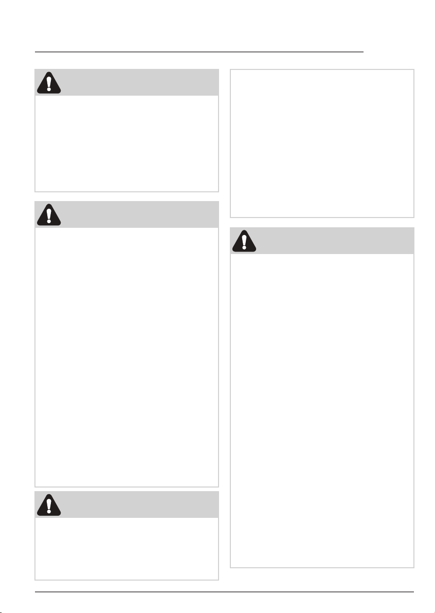
WARNING
For Your Safety
• Do not store or use gasoline or other
flammable vapors and liquids in the
vicinity of this or any other appliance.
Read product labels for flammability and
other warnings.
• Discard water from bucket. Water is not
potable and cannot be used for drinking.
WARNING
Electrical Information
• For your safety and protection, this
dehumidifier is equipped with a
three-prong grounding plug on the power
cord. Do not, under any circumstances,
cut or remove the round ground prong
from the plug.
• Your dehumidifier must be plugged
directly into a properly grounded and
polarized three-prong receptacle. lf the
wall receptacle you intend to use will not
accept a three-prong plug, or if you are
not sure the outlet is adequately grounded
or protected by a time delay fuse or circuit
breaker, have a qualified electrician install
the proper outlet according to the
National Electrical Code and applicable
local codes and ordinances. Do not use an
extension cord or an adapter plug.
• Never unplug the dehumidifier by pulling
on the power cord. Always grip the plug
firmly and pull straight out from the
receptacle.
• Do not pinch, bend, or knot the power
cord.
WARNING
Child Safety Precautions
• Destroy the carton, plastic bags, and any
packing materials immediately after the
dehumidifier is unpacked. Children should
never use these items for play.
• Do not leave children unattended in an
area where the appliance is operating. Do
not allow them to sit or stand on the
appliance.
• This appliance is not intended for use by
persons (including children) with reduced
physical, sensory or mental capabilities or
lack of experience and knowledge, unless
they have been given supervision or
instruction concerning use of the
appliance by a person responsible for their
safety.
• Children should be supervised to ensure
that they do not play with the appliance.
SAFETY PRECAUTIONS
DANGER! Avoid Serious Injury or Death
• This dehumidifier contains no
user-serviceable parts. Always call an
authorized Electrolux servicer for repairs.
• Do not insert or place fingers or objects
into the air discharge area or back grille of
the unit.
• Do not start or stop the dehumidifier by
unplugging the power cord or turning off
the power at the electrical box.
• Do not cut or damage the power cord. Do
not pull on the power cord.
• If the power cord is damaged, it should
only be replaced by an authorized
Electrolux servicer.
• In the event of a malfunction (sparks,
burning smell, etc.), immediately stop the
operation, disconnect the power cord, and
call an authorized Electrolux servicer.
• Do not operate the dehumidifier with wet
hands. Do not drink any water from the
dehumidifier.
• If the supply cord is damaged, it must be
replaced by the manufacturer, its service
agent or similarly qualified persons in
order to avoid a hazard.
• The appliance shall be installed in
accordance with national wiring
regulations.
Page 4
4 IMPORTANT SAFETY INSTRUCTIONS
SAFETY PRECAUTIONS
CAUTION! Avoid Injury or damage to the
unit or other property
• Do not direct airflow at fireplaces or other
heat related sources as this could cause
flare ups.
• Do not climb on or place objects on the
unit. Do not hang objects off the unit.
• Do not place containers with liquids on the
unit.
• Turn off the dehumidifier at the power
source when it will not be used for an
extended period of time.
• Operate the unit with air filter in place.
• Do not block or cover the intake grille,
discharge area and outlet ports.
• Ensure that any electrical/electronic
equipment is one yard away from the unit.
• Do not use or store flammable gases near
the unit.
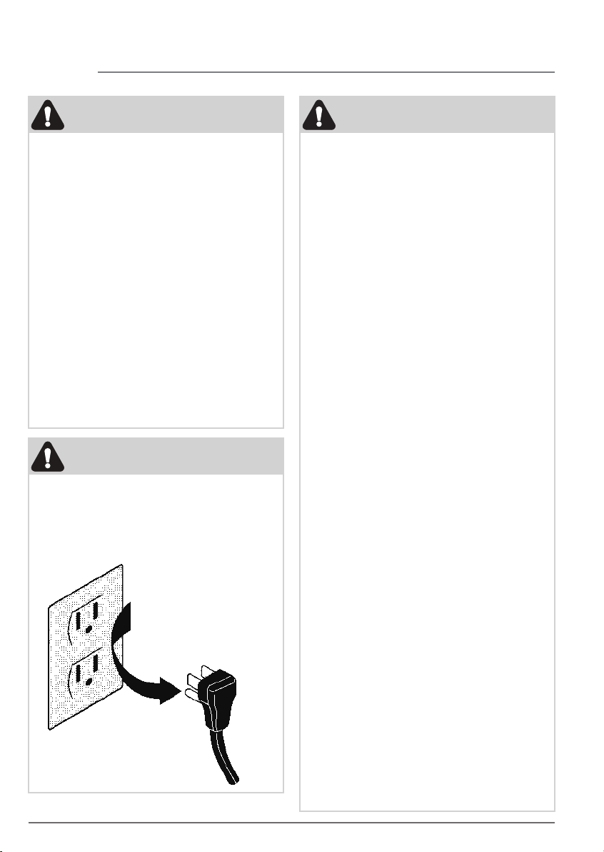
WARNING
Avoid fire hazard or electric shock. Do not
use an extension cord or an adaptor plug.
Do not remove any prong from the power
cord.
Grounding type wall receptacle
Do not, under any
circumstances, cut,
remove, or bypass the
grounding prong.
Power supply cord
with 3-prong grounding
plug
WARNING
FOR FLAMMABLE REFRIGERANT
• Servicing shall only be performed as
recommended by the equipment
manufacturer. Maintenance and repair
requiring the assistance of other skilled
personnel shall be carried out under the
supervision of the person competent in
the use of flammable refrigerants.
• DO NOT modify the length of the power
cord or use an extension cord to power
the unit.
• DO NOT share a single outlet with other
electrical appliances. Improper power
supply can cause fire or electrical shock.
• Please follow the instruction carefully to
handle, install, clear, service the air
conditioner to avoid any damage or
hazard.
• Flammable Refrigerant R32 is used within
air conditioner. When maintaining or
disposing the air conditioner, the
refrigerant (R32) shall be recovered
properly, shall not discharge to air
directly.
• Compliance with national gas regulations
shall be observed.
• Keep ventilation openings clear of
obstruction.
• The appliance shall be stored so as to
prevent mechanical damage from
occurring.
• A warning that the appliance shall be
stored in a well-ventilated area where the
room size corresponds to the room area
as specified for operation.
• Any person who is involved with working
on or breaking into a refrigerant circuit
should hold a current valid certificate from
an industry-accredited assessment
authority, which authorises their
competence to handle refrigerants safely
in accordance with an industry recognised
assessment specification.
Examples for such working procedures are:
• breaking into the refrigerating circuit;
• opening of sealed components;
• opening of ventilated enclosures.
Page 5

5IMPORTANT SAFETY INSTRUCTIONS
• No any open fire or device like switch
which may generate spark/arcing shall be
around air conditioner to avoid causing
ignition of the flammable refrigerant used.
Please follow the instruction carefully to
store or maintain the air conditioner to
prevent mechanical damage from
occurring.
• Do not use means to accelerate the
defrosting process or to clean, other than
those recommended by the manufacturer.
• The appliance shall be stored in a room
without continuously operating ignition
sources (for example: open flames, an
operating gas appliance) and ignition
sources or (for example: an operating
electric heater) close to the appliance.
• Do not pierce or burn.
• Be aware that the refrigerants may not
contain an odour.
1. Transport of equipment containing
flammable refrigerants.
See transport regulations.
2. Marking of equipment using signs
See local regulations.
3. Disposal of equipment using flammable
refrigerants
See national regulations.
4. Storage of equipment/appliances
The storage of equipment should be in
accordance with the manufacturer's
instructions.
5. Storage of packed (unsold) equipment
Storage package protection should be
constructed such that mechanical
damage to the equipment inside the
package will not cause a leak of the
refrigerant charge. The maximum number
of pieces of equipment permitted to be
stored together will be determined by
local regulations.
6. Information on servicing
a) Checks to the area
Prior to beginning work on systems
containing flammable refrigerants, safety
checks are necessary to ensure that the
risk of ignition is minimised. For repair to
the refrigerating system, the following
precautions shall be complied with prior
to conducting work on the system.
b) Work procedure
Work shall be undertaken under a
controlled procedure so as to minimise
the risk of a flammable gas or vapour
being present while the work is being
performed.
c) General work area
All maintenance staff and others working
in the local area shall be instructed on
the nature of work being carried out.
Work in confined spaces shall be
avoided. The area around the workspace
shall be sectioned off. Ensure that the
conditions within the area have been
made safe by control of flammable
material.
d) Checking for presence of refrigerant
The area shall be checked with an
appropriate refrigerating detector prior
to and during work, to ensure the
technician is aware of potentially
flammable atmospheres. Ensure that the
leak detection equipment being used is
suitable for use with flammable
refrigerants, i.e. non-sparking,
adequately sealed or intrinsically safe.
e) Presence of fire extinguisher
If any hot work is to be conducted on the
refrigeration equipment or any
associated parts, appropriate fire
extinguishing equipment shall be
available to hand. Have a dry powder or
CO2 fire extinguisher adjacent to the
charging area.
f) No ignition sources
No person carrying out work in relation
to a refrigerating system which involves
exposing any pipe work that contains or
has contained flammable refrigerant
shall use any sources of ignition in such a
manner that it may lead to the risk of fire
or explosion. All possible ignition
sources, including cigarette smoking,
should be kept sufficiently far away from
the site of installation, repairing,
removing and disposal, during which
flammable refrigerant can possibly be
released to the surrounding space. Prior
to work taking place, the area around the
Page 6

6
IMPORTANT SAFETY INSTRUCTIONS
equipment is to be surveyed to make sure
that there are no flammable hazards or
ignition risks. No Smoking signs shall be
displayed.
g) Ventilated area
Ensure that the area is in the open or that
it is adequately ventilated before
breaking into the system or conducting
any hot work. A degree of ventilation shall
continue during the period that the work
is carried out. The ventilation should
safely disperse any released refrigerant
and preferably expel it externally into the
atmosphere.
h) Checks to the refrigerating equipment
Where electrical components are being
changed, they shall be fit for the purpose
and to the correct specification. At all
times the manufacturer's maintenance
and service guidelines shall be followed. If
in doubt consult the manufacturer's
technical department for assistance. The
following checks shall be applied to
installations using flammable refrigerants:
The actual refrigerant charge is in
accordance with the room size within
which the refrigerant containing parts are
installed; The ventilation machinery and
outlets are operating adequately and are
not obstructed; If an indirect refrigerating
circuit is being used, the secondary circuit
shall be checked for the presence of
refrigerant; Marking to the equipment
continues to be visible and legible.
Markings and signs that are illegible shall
be corrected; Refrigerating pipe or
components are installed in a position
where they are unlikely to be exposed to
any substance which may corrode
refrigerant containing components,
unless the components are constructed
of materials which are inherently resistant
to being corroded or are suitably
protected against being so corroded.
i) Checks to electrical devices
Repair and maintenance to electrical
components shall include initial safety
checks and component inspection
procedures. If a fault exists that could
compromise safety, then no electrical
supply shall be connected to the circuit
until it is satisfactorily dealt with. If the
fault cannot be corrected immediately
but it is necessary to continue operation,
an adequate temporary solution shall be
used. This shall be reported to the owner
of the equipment so all parties are
advised. Initial safety checks shall include:
That capacitors are discharged: this shall
be done in a safe manner to avoid
possibility of sparking; That there no live
electrical components and wiring are
exposed while charging, recovering or
purging the system; That there is
continuity of earth bonding.
7. Repairs to sealed components
a) During repairs to sealed components, all
electrical supplies shall be disconnected
from the equipment being worked upon
prior to any removal of sealed covers, etc.
If it is absolutely necessary to have an
electrical supply to equipment during
servicing, then a permanently operating
form of leak detection shall be located at
the most critical point to warn of a
potentially hazardous situation.
b) Particular attention shall be paid to the
following to ensure that by working on
electrical components, the casing is not
altered in such a way that the level of
protection is affected. This shall include
damage to cables, excessive number of
connections, terminals not made to
original specification, damage to seals,
incorrect fitting of glands, etc. Ensure
that apparatus is mounted securely.
Ensure that seals or sealing materials
have not degraded such that they no
longer serve the purpose of preventing
the ingress of flammable atmospheres.
Replacement parts shall be in accordance
with the manufacturer's specifications.
NOTE: The use of silicon sealant may inhibit
the effectiveness of some types of leak
detection equipment. Intrinsically safe
components do not have to be isolated
prior to working on them.
8. Repair to intrinsically safe components
Do not apply any permanent inductive or
capacitance loads to the circuit without
Page 7

7IMPORTANT SAFETY INSTRUCTIONS
ensuring that this will not exceed the
permissible voltage and current
permitted for the equipment in use.
Intrinsically safe components are the only
types that can be worked on while live in
the presence of a flammable atmosphere.
The test apparatus shall be at the correct
rating. Replace components only with
parts specified by the manufacturer.
Other parts may result in the ignition of
refrigerant in the atmosphere from a leak.
9. Cabling
Check that cabling will not be subject to
wear, corrosion, excessive pressure,
vibration, sharp edges or any other
adverse environmental effects. The check
shall also take into account the effects of
aging or continual vibration from sources
such as compressors or fans.
10.Detection of flammable refrigerants
Under no circumstances shall potential
sources of ignition be used in the
searching for or detection of refrigerant
leaks. A halide torch (or any other
detector using a naked flame) shall not be
used.
The following leak detection methods are
deemed acceptable for systems
containing flammable refrigerants.
Electronic leak detectors shall be used to
detect flammable refrigerants, but the
sensitivity may not be adequate, or may
need re-calibration. (Detection
equipment shall be calibrated in a
refrigerant-free area). Ensure that the
detector is not a potential source of
ignition and is suitable for the refrigerant
used. Leak detection equipment shall be
set at a percentage of the LFL of the
refrigerant and shall be calibrated to the
refrigerant employed and the appropriate
percentage of gas (25 % maximum) is
confirmed. Leak detection fluids are
suitable for use with most refrigerants but
the use of detergents containing chlorine
shall be avoided as the chlorine may react
with the refrigerant and corrode the
copper pipe-work. If a leak is suspected,
all naked flames shall be
removed/extinguished. If a leakage of
refrigerant is found which requires
brazing, all of the refrigerant shall be
recovered from the system, or isolated
(by means of shut off valves) in a part of
the system remote from the leak.
Removal of refrigerant shall be according
to Removal and evacuation.
11. Removal and evacuation
When breaking into the refrigerant circuit
to make repairs – or for any other
purpose–conventional procedures shall
be used. However, for flammable
refrigerants it is important that best
practice be followed, since flammability is
a consideration. The following procedure
shall be adhered to:
a) safely remove refrigerant following local
and national regulations;
b) purge the circuit with inert gas;
c) evacuate (optional for A2L);
d) purge with inert gas (optional for A2L);
e) open the circuit by cutting or brazing.
The refrigerant charge shall be recovered
into the correct recovery cylinders if
venting is not allowed by local and
national codes. For appliances containing
flammable refrigerants, the system shall
be purged with oxygen-free nitrogen to
render the appliance safe for flammable
refrigerants. This process might need to
be repeated several times. Compressed
air or oxygen shall not be used for
purging refrigerant systems. For
appliances containing flammable
refrigerants, refrigerants purging shall be
achieved by breaking the vacuum in the
system with oxygen-free nitrogen and
continuing to fill until the working
pressure is achieved, then venting to
atmosphere, and finally pulling down to a
vacuum (optional for A2L). This process
shall be repeated until no refrigerant is
within the system (optional for A2L).
When the final oxygen-free nitrogen
charge is used, the system shall be vented
down to atmospheric pressure to enable
work to take place. Ensure that the outlet
for the vacuum pump is not close to any
potential ignition sources and that
ventilation is available.
Page 8

8 IMPORTANT SAFETY INSTRUCTIONS
12. Charging procedures
In addition to conventional charging
procedures, the following requirements
shall be followed. Ensure that
contamination of different refrigerants
does not occur when using charging
equipment. Hoses or lines shall be as
short as possible to minimise the amount
of refrigerant contained in them.
Cylinders shall be kept in an appropriate
position according to the instructions.
Ensure that the refrigeration system is
earthed prior to charging the system with
refrigerant. Label the system when
charging is complete (if not already).
Extreme care shall be taken not to overfill
the refrigeration system. Prior to
recharging the system it shall be pressure
tested with OFN. The system shall be leak
tested on completion of charging but
prior to commissioning. A follow up leak
test shall be carried out prior to leaving
the site.
13. Decommissioning
Before carrying out this procedure, it is
essential that the technician is completely
familiar with the equipment and all its
detail. It is recommended good practice
that all refrigerants are recovered safely.
Prior to the task being carried out, an oil
and refrigerant sample shall be taken in
case analysis is required prior to re-use of
reclaimed refrigerant. It is essential that
electrical power is available before the
task is commenced.
a) Become familiar with the equipment and
its operation.
b) Isolate system electrically.
c) Before attempting the procedure ensure
that: Mechanical handling equipment is
available, if required, for handling
refrigerant cylinders; All personal
protective equipment is available and
being used correctly; The recovery
process is supervised at all times by a
competent person; Recovery equipment
and cylinders conform to the appropriate
standards.
d) Pump down refrigerant system, if
possible.
e) If a vacuum is not possible, make a
manifold so that refrigerant can be
removed from various parts of the
system.
f) Make sure that cylinder is situated on the
scales before recovery takes place.
g) Start the recovery machine and operate
in accordance with instructions.
h) Do not overfill cylinders. (No more than
80% volume liquid charge).
i) Do not exceed the maximum working
pressure of the cylinder, even
temporarily.
j) When the cylinders have been filled
correctly and the process completed,
make sure that the cylinders and the
equipment are removed from site
promptly and all isolation valves on the
equipment are closed off.
k) Recovered refrigerant shall not be
charged into another refrigeration system
unless it has been cleaned and checked.
14.
Labelling
Equipment shall be labelled stating that it
has been de-commissioned and emptied
of refrigerant. The label shall be dated
and signed. Ensure that there are labels
on the equipment stating the equipment
contains flammable refrigerant.
15. Recovery
When removing refrigerant from a
system, either for servicing or
decommissioning, it is recommended
good practice that all refrigerants are
removed safely. When transferring
refrigerant into cylinders, ensure that only
appropriate refrigerant recovery
cylinders are employed. Ensure that the
correct number of cylinders for holding
the total system charge is available. All
cylinders to be used are designated for
the recovered refrigerant and labelled for
that refrigerant (i.e. special cylinders for
the recovery of refrigerant). Cylinders
shall be complete with pressure relief
valve and associated shut-off valves in
good working order. Empty recovery
cylinders are evacuated and, if possible,
cooled before recovery occurs.
Page 9
9IMPORTANT SAFETY INSTRUCTIONS
The recovery equipment shall be in good
working order with a set of instructions
concerning the equipment that is at hand
and shall be suitable for the recovery of
flammable refrigerants. In addition, a set
of calibrated weighing scales shall be
available and in good working order.
Hoses shall be complete with leak-free
disconnect couplings and in good
condition. Before using the recovery
machine, check that it is in satisfactory
working order, has been properly
maintained and that any associated
electrical components are sealed to
prevent ignition in the event of a
refrigerant release. Consult manufacturer
if in doubt. The recovered refrigerant shall
be returned to the refrigerant supplier in
the correct recovery cylinder, and the
relevant Waste Transfer Note arranged.
Do not mix refrigerants in recovery units
and especially not in cylinders.
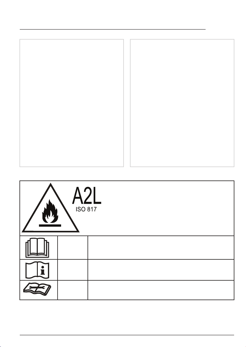
CAUTION:
Risk of fire flammable materials
IMPORTANT NOTE: Read this manual carefully
before installing or operating your new air
conditioning unit. Make sure to save this manual
for future reference.
If compressors or compressor oils are to
be removed, ensure that they have been
evacuated to an acceptable level to make
certain that flammable refrigerant does
not remain within the lubricant. The
evacuation process shall be carried out
prior to returning the compressor to the
suppliers. Only electric heating to the
compressor body shall be employed to
accelerate this process. When oil is
drained from a system, it shall be carried
out safely.
Non-duct connected appliances
containing A2L refrigerants with the
supply and return air openings in the
conditioned space may have the body of
the appliance may be installed in open
areas such as false ceilings not being used
as return air plenums, as long as the
conditioned air does not directly
communicate with the air of the false
ceiling.
CAUTION
CAUTION
CAUTION
This symbol shows that the operation manual should be read
carefully.
This symbol shows that information is available such as the
operating manual or installation manual.
This symbol shows that a service personnel should be
handling this equipment with reference to the installation
manual.
Page 10
10
IMPORTANT SAFETY INSTRUCTIONS
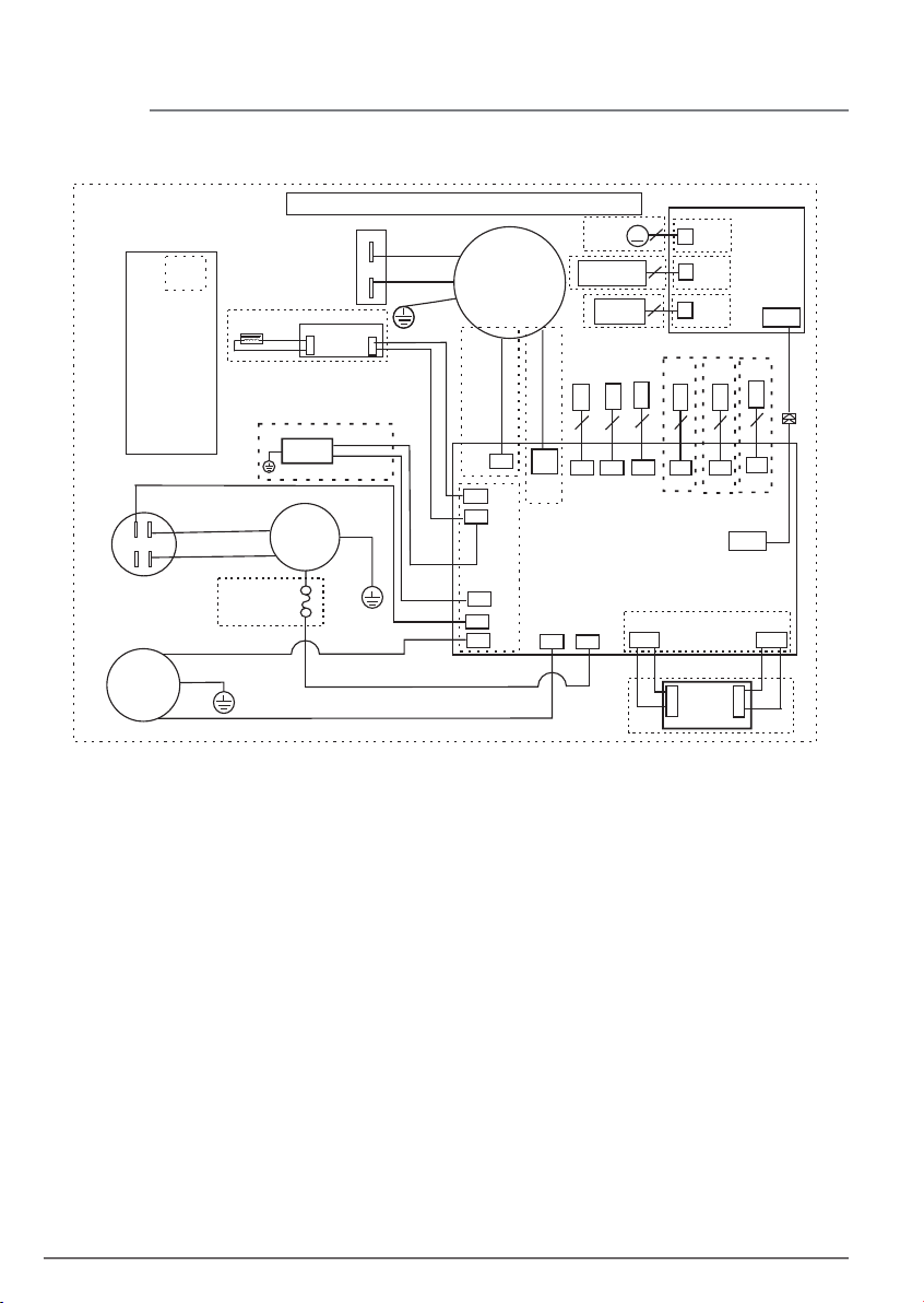
Wiring Diagram
16020100001654
Notes:
This symbol
indicates
the element
is optional,
the actual
shape shall
prevail
BLUE
BLUE
BLACK
COMP.
CAPACITOR
WHITE(OR BLUE OR BLACK)(N)
POWER
Y/G(or GREEN)
Notes:
Display and Fan's conntors must be match the actual indicates.
BLUE
BROWN
CN1
RED
BLACK
PUMP
BLACK(or BLUE)
Y/G
FAN
CAPACITOR
OPTIONAL
CN2
RED
ION
DC POWER
BOARD
COMP.
M
M
~
S
C
Y/G
OverLoad
Protector
BLACK(OR BROWN OR RED)(L)
Y/G
RED
BLACK(or BLUE)
FAN
P4
P10
WHITE
CN4
P9
P6
MAIN BOARD
P7
P2
P8
RED
TOP
M
CN5
WIFI
CN11
CN12
SWITCH
DISPLAY
BOARD
(or CN13)
CN7
STEP
TOUCH/LIGHT
PANEL
WIFI
WATER
PIPE
SWITCHTEMP.
CN3
CN2
HUMI.
SENSOR
CN1
CN10
CN5
(or CN6/CN6A/CN6B/CN6C/CN10)
CN14
P1
1 3
POWER
3
1
BOARD
CN1
CN2
1
2
CN10
SWITCH
CN6B
CN15
1 2
Page 11
11LOCATION & HOW IT WORKS
Location
Selecting a Location
IMPORTANT:
1. Dehumidifier must be operated in an
enclosed area to be most eective. Close
all doors, windows, and other outside
openings to the room. The eectiveness of
the dehumidifier depends on the rate at
which new moisture-laden air enters the
room.
2. Place dehumidifier in a location that does
not restrict the airflow of the air intake and
air outlet.
3. A dehumidifier operating in a basement
will have little or no eect in drying an
adjacent enclosed storage area, such as a
closet, unless there is adequate circulation
of air in and out of the area. lt may be
necessary to install a second dehumidifier
in the enclosed area for satisfactory drying.
4. The dehumidifier must be installed on a
level floor that will support it with a full
bucket of water.
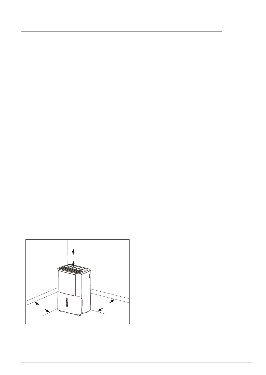
5. There should be a minimum of 12 inches
clearance around the dehumidifier. The
unit will produce heat while in operation
and should not be operated in an enclosed
small space like a closet.
How It Works
When the unit is started, the fan begins to
pull moisture-laden air across the
dehumidifying coils. The coils condense or
draw moisture from the air, and air flows
through the air outlet louvers into the room
as dry, warm air. Moisture removed from air is
collected in a bucket on the front of the
dehumidifier.
The unit is designed to operate between 41°F
(5°C), and 89°F (32°C) and between
30%(RH) and 80%(RH). The unit will not
work properly if the temperature is out of this
temperature range, or the performance of
the unit will fall greatly.
The "Compressor" circuit has an automatic 3
minute time delayed start if the unit is turned
o and on quickly. This prevents overheating
of the compressor and possible circuit
breaker tripping. Make sure the tank is fitted
correctly otherwise unit will not turn on.
Do not Block at least 24"
12"
12"
Page 12
12 DEHUMIDIFIER FEATURES & OPERATING INSTRUCTIONS
Dehumidifier Features
ELECTRONIC CONTROL
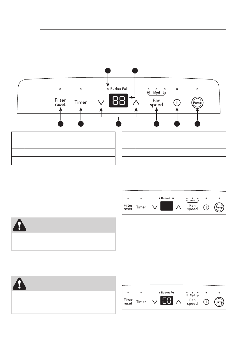
Before you begin, thoroughly familiarize yourself with the control panel and all its functions
(as shown below).
CB
G E D H
A Check Filter Reset Button
B Bucket Full Indicator
C Displays Humidity
D Turns Unit On Or O
Operating Instructions
Allow the unit to reach room temperature
before operating.
To begin operating the dehumidifier, follow
these steps:
NOTE
Unit must be upright for one hour prior to
operating.
1. Plug the power cord into a properly
grounded 115 volt AC outlet.
NOTE
FA
E Sets Fan Speed
F Adjusts Humidity
G Sets Timer
H Pump Feature
2. To turn the unit on, press the ON/OFF
button. The unit will run in the factory
setting of CONTINUOUS and high fan
speed. In the CONTINUOUS mode, the unit
will only display CO and not the room
humidity. It is recommended you leave the
unit running in the CONTINUOUS setting
for the first three or four days until the
sweating and dampness odors have
stopped.
If the "BUCKET FULL" light is on, remove
the bucket and re-install to reset the float
switch.
Page 13
13OPERATING INSTRUCTIONS
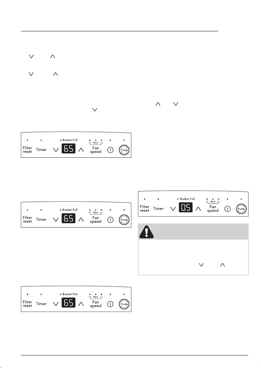
3. After a few days when the Relative
Humidity has declined, press the HUMIDITY
( ) or ( ) buttons to choose a value
between 35% to 85%, so the room is kept
at a comfortable humidity. Pressing the
( ) or ( ) buttons will change the
humidity selection in 5% increments. 5
seconds after you have set the desired
humidity, the readout will display the
actual room humidity. If at any time you
want to return to the CONTINUOUS Mode,
pressing the HUMIDITY ( ) button will
lower the Relative Humidity through 5%
decrements until the display reads CO.
4. You can also use the FAN SPEED button to
change the fan speed to Hi, Med or Lo. The
indicator light will show the setting you
have selected. A higher fan speed will
result in quicker moisture removal.
6. The TIMER function enables you to either
Delay Start or Delay Stop the unit in the
choice from 0.5 hour to 24 hours. If the unit
is running, then selecting Timer will turn
the unit o in the hours that will be set
(Delay Stop). If the unit is o, then
selecting Timer will turn the unit on in the
hours that will be set (Delay Start). TIMER
setting: First press TIMER button, then
adjust timer setting, by tapping or holding
the ( ) or ( ) button to change the delay
timer at 0.5 hour increments, up to 10
hours, then by 1 hour increments up to 24
hours. The control will count down the time
remaining (8h, 7.5h, 7h etc.) until the unit
either starts or stops. For the Delay Start,
the fan speed and humidity maintained will
be the same as previous setting. After
TIMER setting finishes, pressing TIMER
button again at any time will stop the
TIMER function. The Delay Start/Stop
Feature will work until the unit either starts
or stops. Once that happens the above
steps have to be repeated.
5. The Filter reset light will illuminate after
250 hours of operation. At this time refer
to the care and cleaning section to remove
and clean the filter. Once the filter has been
cleaned and replaced, simply press the
Filter reset button to extinguish the light.
NOTE
1. Before entering TIMER setting, make sure
power is being supplied to the unit.
2. Before entering TIMER setting, make sure
pressing HUMIDITY ( ) or ( ) button
sets one desired room humidity first.
7. Press PUMP button, the unit will enter
water pump mode. Pump Mode Indicator
will be on. When the water tank is full of
water, the pump will start to pump water
automatically. The pump will stop
automatically after the water tank have
been empty.
Page 14
14 OPERATING INSTRUCTIONS
NOTE:
• Pump drain hose must be well connected
for this mode.
• If the Pump indicator and Bucket Full
indicator flash simultaneously, after
pressing the Pump button, check if the
pump drain hose in the bucket is installed
properly.
8. To shut the unit down, press the ON/OFF
button.
Note: After a power outage, the unit will
memorize the last setting and return the unit
to the same setting once power is restored.
Fault Codes
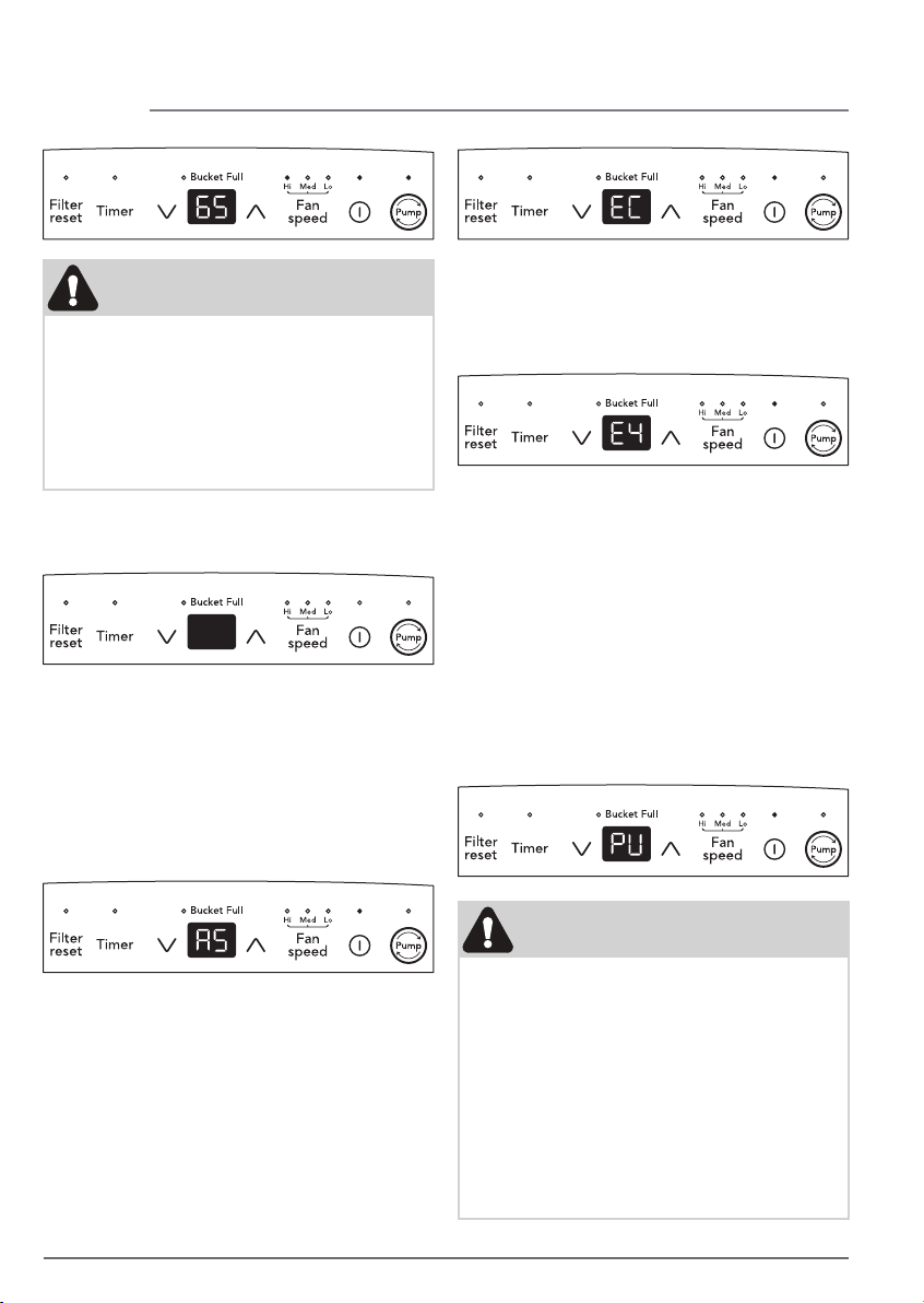
1. If the display reads "AS" or "ES" , a sensor
has failed. Contact your Authorized
Frigidaire® Service Center.
3. If the display reads “E4”, the
communication between display PCB and
main control PCB is faulty. Contact your
Authorized Frigidaire® Service Center.
4. If the display reads "PU", check the
following operating conditions: a. Make
sure the pump drain hose is well connected.
b. Check that the hose is not blocked,
kinked or frozen. c. Remove and empty the
water bucket to check the bucket pickup
for blockage of dirt or alge. d. Turn o the
unit and restart it under normal operating
conditions. e. Unplug the unit and plug it in
again under normal operating conditions. If
the "PU" code persists, contact your
Authorized Frigidaire® Service Center.
2. If the display reads "EC" , check the
following operating conditions. Outlet
voltage should be 115V±10% and the
surrounding temperature should be with in
the range of 41 °F to 89 °F. Unplug the unit
and plug it in again under normal operating
conditions. If the "EC" code persists,
contact your Authorized Frigidaire® Service
Center.
NOTE:
1. If your unit does not pump water, you
need to check below first: a. Check the
pump is turned on. b. The unit will not
pump untill it reaches the full bucket
point.
2. Please follow the steps described in
“Emptying the Bucket” to remove and
empty the water bucket.
3. Please follow the steps described in “Care
and Cleaning” to clean the unit regularly
to prevent dirt or alge.
Page 15
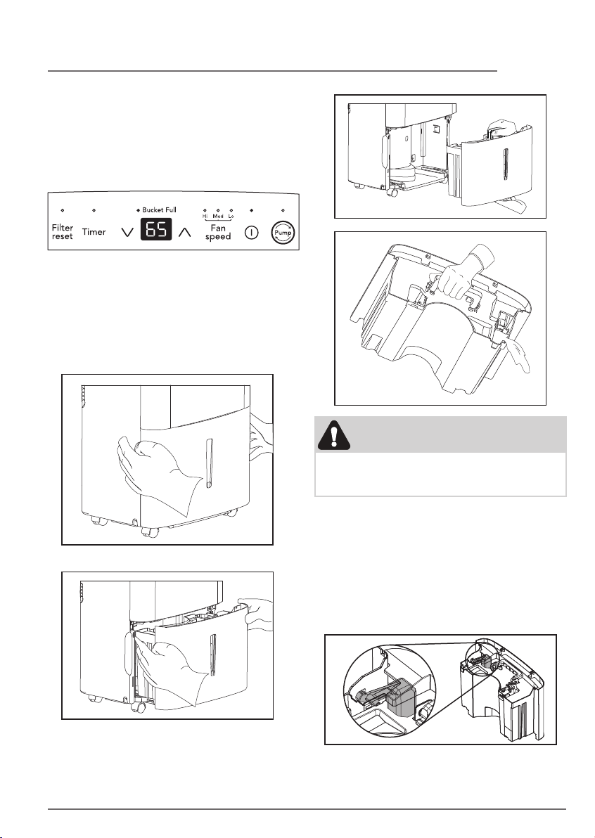
Removing Collected Water
1. Emptying the Bucket:
a. When the bucket is full, the unit will shut
down and the BUCKET FULL indicator will
illuminate.
b. Do not move the unit at this time otherwise
water may spill on the floor.
c. Press sides of bucket gently to unclip the
bucket from the unit.
d. Remove the bucket as shown in the
photographs below and empty the bucket.
15OPERATING INSTRUCTIONS
WARNING
Discard water from bucket. Water is not
potable and cannot be used for drinking.
e. Replace the empty bucket back into the
unit and once seated correctly, the unit will
start up again.
f. You should hear a click when the bucket is
in the correct position.
If the bucket full light does not extinguish,
check that the float is correctly snapped in
place.
Page 16

16 OPERATING INSTRUCTIONS
2. Continuous Drainage:
a. For continuous drainage operation, you will
need a garden hose and a drain nearby to
discharge the water into.
b. Unscrew the drain cap on the back side of
the unit. (fig.1)
e. Make sure the hose is secure so there are no
leaks.
f. Direct the hose toward the drain, making
sure that there are no kinks that will stop
fig. 1
c. Insert the female threaded end of the hose
onto the drain connector of the unit. (fig.2)
the water flowing.
g. Place the end of the hose into the drain.
(fig.4)
fig. 3
fig. 2
d. Screw the garden hose onto the threaded
portion of the drain connector. (fig.3)
fig. 3
h. Select the desired humidity setting and fan
speed on the unit for continuous draining
to start.
Page 17
17CARE AND CLEANING
NOTE
1. Check the seal between the hose and the
drain connector. If there is a small leak
then replace the hose gasket and
re-tighten the hose.
2. It is recommended that a Dehumidifier
Drain Hose - 1/2" (12.7 mm) or larger be
used. Make sure there are no kinks or
elevations in the hose.
3. When a hose is not attached to the drain
connector, please ensure drain cap is
screwed securely to the connector to
prevent leakages.
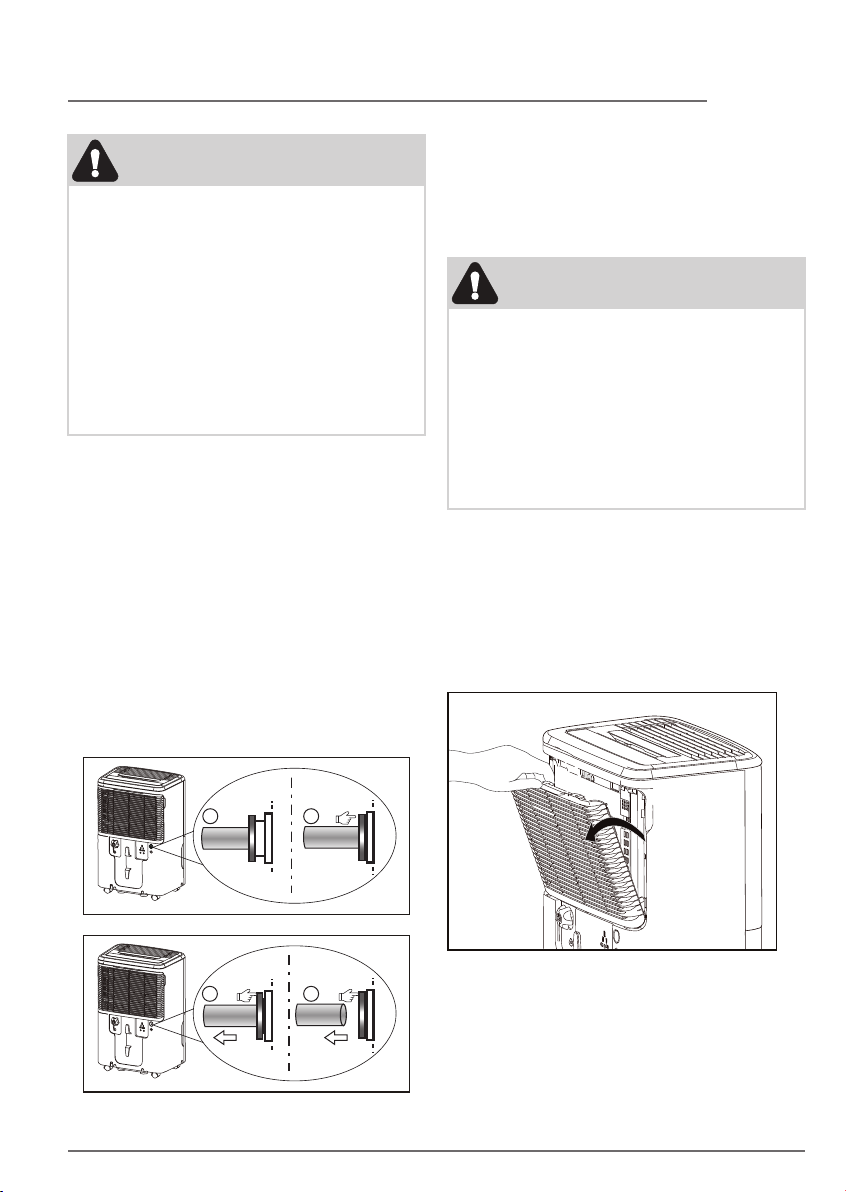
3. Pump function:
To connect pump drain hose:
a. Press the tightening ring of drainage
joint;(fig.11)
b. Keep pressing the grey ring while pulling
out the plug. (fig.12);
c. Insert the drain hose onto the drainage
joint, make sure it is connected well so that
it is fully seated.
d. Place the other end of the drain hose in the
location you want the water to go to a floor
drain, a water container, or through a
basement window to the outdoors.
To remove pump drain hose:
a. Press the tightening ring of drainage joint.
b. Pull out the drain hose.
c. Place the plug back to the joint.
NOTE:
1. The maximum distance and the rise may
be 5m from the unit. Exceeding this
distance may damage the unit or cause
leaks.
2. If removing the hose to use in Bucket
mode, please reinsert the drain plug to
prevent accidental water leakage. (You
still need to press the tightening ring
when removing the hose.)
Care and Cleaning
1. Filter
Clean the filter every two weeks based on
normal operating conditions.
To remove the filter:
a. Open the back grille.
1 2
3 4
fig.11
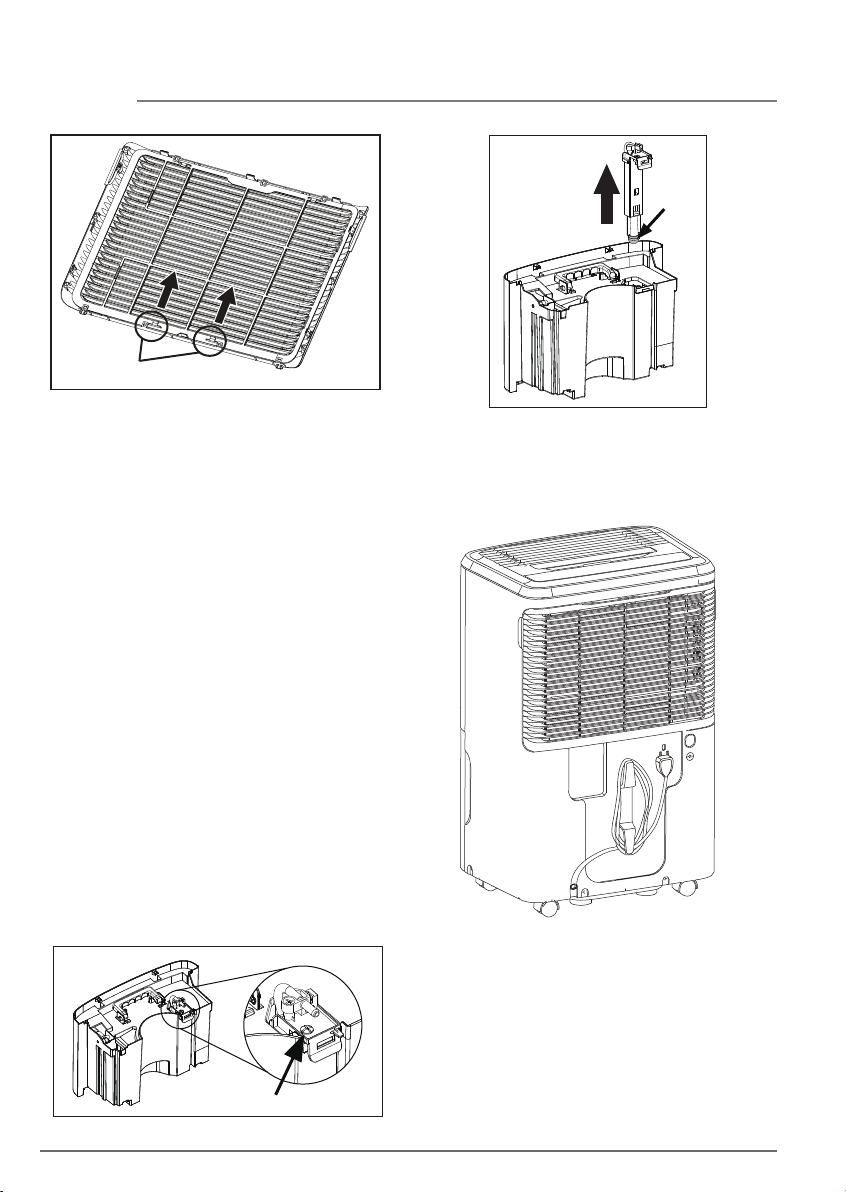
b. Detach the filter from the back of the grille
by pressing the tabs as shown below.
fig.12
Page 18
18 STORAGE
Tabs
c. Wash the filter with clean water then dry.
d. Re-install the filter.
2. Cabinet
a. Dust cabinet with an oil-free cloth, or using
a damp cloth.
b. Vacuum grill using brush attachment.
3. Water Bucket
Clean the Water Bucket every two weeks
based on normal operating conditions.
a. Clean bucket with warm water and
detergent.
b. Clean the pump filter at the same time in
cleaning the bucket.
4. Pump filter
Clean the pump filter every two weeks based
on normal operating conditions.
a. Take out the water bucket from the unit.
b. Remove the screw as shown in fig.20.
c. Take out the pump drainage structure and
clean the filter at the button of the hose.
fig.21
d. Reinstall the filter and pump drainage
structure to the water bucket.
Filter
fig.21
Storage
When unit is not in use, unplug and use the
cord wrap shown for your model type.
Remove this screw
fig.20
Page 19
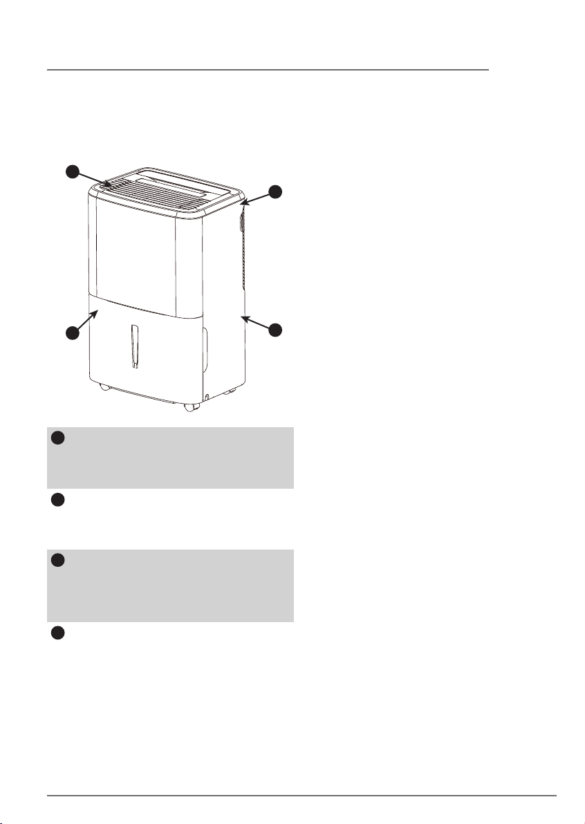
Normal Sounds
2
19NORMAL SOUNDS
3
1
1
Dripping Sound
The sound of dripping water may be
heard during the dehumidification
cycle.
2
Sound of Rushing Air
At the top of the unit, you may hear the
sound of rushing air being moved by
the fan.
3
Gurgle/Hiss
“Gurgling or hissing” noise may be
heard due to refrigerant passing
through evaporator during normal
operation.
4
High pitched Chatter
Today’s high eciency compressors
may have a high pitched chatter during
the dehumidification cycle.
4
Page 20

20BEFORE YOU CALL
Before calling for service, review this list. It may save you time and expense. This list includes
common occurrences that are not the result of defective workmanship or materials in this
appliance.
SOLUTIONOCCURRENCE
• Wall plug disconnected. Push plug firmly into wall outlet.
• House fuse blown or circuit breaker tripped. Replace fuse with time delay
type or reset circuit breaker.
• The dryness level you selected has been reached. Dehumidifier automatically
shuts o when selected amount of moisture has been removed from the air.
If you want to remove more moisture, Select 'CONTINUOUS' by using the
Dehumidifier does not
operate.
Dehumidifier runs too
much.
Dehumidifier is
operating but room is
not dry enough.
Frost appears on coils
behind the filter
Fan noise.
humidity button or knob. After the dehumidifier starts, reset the control to
the desired setting.
• Bucket not installed properly. See “Removing Collected Water“.
• Water in the bucket has reached its preset level. Dehumidifier automatically
turns o when this occurs. Empty bucket and return bucket to position.
• Dehumidifier is not turned on. Turn unit on.
• “BUCKET FULL“ light is on. Remove bucket, empty water and re-install
correctly.
• Windows or doors near dehumidifier are open to outdoors. Close all windows
or doors to outside.
• Area to be dehumidified is too large. Check with your dealer to see if capacity
is adequate.
• Air movement through dehumidifier is blocked. Grill may be dirty. Use brush
attachment of vacuum cleaner to clean grill. See “Care and Cleaning”.
Dehumidifier must be placed in a space that does not restrict air flowing into
the rear coil or out of the front grill.
• Dehumidifier has been installed or restarted recently. The higher the
moistuire in the room, the longer the dehumidifier will operate.
• Dehumidifier is in the CONTINUOUS mode and will remain on in this mode,
use the humidity button or knob to set a RH% higher level.
• Humidity setting is too high. Press the HUMIDITY button or rotate knob to a
lower setting or choose CONTINUOUS for maximum dryness.
• Dehumidifier has been installed or restarted recently. The higher the moisture
in the room air, the longer it takes for the room air to become dry.
• Dehumidifier does not have sufficient clearance to operate. Air flow to the air
outlet is blocked. See “Selecting a Location”.
• Room temperature is too low. Unit will not operate satisfactorily if the room
temperature is below 41°F(5°C). See “Operating Conditions”.
• Refer to causes under DEHUMlDIFIER RUNS TOO MUCH.
• Dehumidifier has been turned on recently. This is normal due to refrigerant
rushing through the coil. Frost will usually disappear within 60 minutes.
• Room Temperature is too low. All models will operate satisfactorily at
temperatures greater than 41°F (5°C).
• Air is moving through the dehumidifier. This is a normal sound.
If These Solutions Fail, Call 1-800-944-9044(US)/1-800-265-8352(Canada)
For Frigidaire® Service.
Page 21
21MAJOR APPLIANCE LIMITED WARRANTY
Your appliance is covered by a limited one-year warranty for functional repairs only. For one year from your
original date of purchase, Electrolux will pay all costs for repairing or replacing any parts of this appliance that
prove to be defective in materials or workmanship when such appliance is installed, used and maintained in
accordance with the provided instructions. After one year from your original date of purchase, the consumer
will be responsible for diagnostic, labor and parts costs as well as any removal, transportation and
reinstallation expenses which are incurred during service on components.
Exclusions
This warranty does not cover the following:
1. Products with original serial numbers that have been removed, altered or cannot be readily determined.
2. Product that has been transferred from its original owner to another party or removed outside the USA or
Canada.
3. Rust on the interior or exterior of the unit.
4. Products purchased "as-is" are not covered by this warranty.
5. Food loss due to any refrigerator or freezer failures.
6. Products used in a commercial setting.
7. Service calls which do not involve malfunction or defects in materials or workmanship, or for appliances
not in ordinary household use or used other than in accordance with the provided instructions.
8. Service calls to correct the installation of your appliance or to instruct you how to use your appliance.
9. Expenses for making the appliance accessible for servicing, such as removal of trim, cupboards, shelves,
etc., which are not a part of the appliance when it is shipped from the factory.
10. Service calls to repair or replace appliance light bulbs, air filters, water filters, other consumables, or
knobs, handles, or other cosmetic parts.
11. Surcharges including, but not limited to, any after hour, weekend, or holiday service calls, tolls, ferry trip
charges, or mileage expense for service calls to remote areas, including the state of Alaska.
12. Damages to the finish of appliance or home incurred during installation, including but not limited to
floors, cabinets, walls, etc.
13. Damages caused by: services performed by unauthorized service companies; use of parts other than
genuine Electrolux parts or parts obtained from persons other than authorized service companies; or
external causes such as abuse, misuse, inadequate power supply, accidents, fires, or acts of God.
DISCLAIMER OF IMPLIED WARRANTIES; LIMITATION OF REMEDIES
CUSTOMER'S SOLE AND EXCLUSIVE REMEDY UNDER THIS LIMITED WARRANTY SHALL BE PRODUCT
REPAIR OR REPLACEMENT AS PROVIDED HEREIN. CLAIMS BASED ON IMPLIED WARRANTIES, INCLUDING
WARRANTIES OF MERCHANTABILITY OR FITNESS FOR A PARTICULAR PURPOSE, ARE LIMITED TO ONE
YEAR OR THE SHORTEST PERIOD ALLOWED BY LAW, BUT NOT LESS THAN ONE YEAR. ELECTROLUX
SHALL NOT BE LIABLE FOR CONSEQUENTIAL OR INCIDENTAL DAMAGES SUCH AS PROPERTY DAMAGE
AND INCIDENTAL EXPENSES RESULTING FROM ANY BREACH OF THIS WRITTEN LIMITED WARRANTY OR
ANY IMPLIED WARRANTY. SOME STATES AND PROVINCES DO NOT ALLOW THE EXCLUSION OR
LIMITATION OF INCIDENTAL OR CONSEQUENTIAL DAMAGES, OR LIMITATIONS ON THE DURATION OF
IMPLIED WARRANTIES, SO THESE LIMITATIONS OR EXCLUSIONS MAY NOT APPLY TO YOU. THIS WRITTEN
WARRANTY GIVES YOU SPECIFIC LEGAL RIGHTS. YOU MAY ALSO HAVE OTHER RIGHTS THAT VARY
FROM STATE TO STATE.
If You Need
Service
This limited warranty only applies in the USA and Canada. In the USA, your appliance is warranted by
Electrolux Major Appliances North America, a division of Electrolux Home Products, Inc. In Canada, your
appliance is warranted by Electrolux Canada Corp. Electrolux authorizes no person to change or add to any
obligations under this warranty. Obligations for service and parts under this warranty must be performed by
Electrolux or an authorized service company. Product features or specifications as described or illustrated are
subject to change without notice.
Keep your receipt, delivery slip, or some other appropriate payment record to establish the
warranty period should service be required. If service is performed, it is in your best interest to
obtain and keep all receipts. Service under this warranty must be obtained by contacting
Electrolux at the addresses or phone numbers below.
USA
1.800.944.9044
Electrolux Major Appliances
10200 David Taylor Drive
Charlotte, NC 28262
1.800.265.8352
Canada
Electrolux Canada Corp.
5855 Terry Fox Way
Mississauga, Ontario, Canada
L5V 3E4
Page 22
welcome
home
Our home is your home. Visit us if you
need help with any of these things:
owner support
accessories
service
registration
(See your registration card
for more information.)
Frigidaire.com
1-800-944-9044
Frigidaire.ca
1-800-265-8352
16120300A29015 (July 2019)
 Loading...