

Frigidaire FES388WGCG Installation Instructions Manual
30" ELECTRIC SLIDE-IN RANGE INSTALLATION INSTRUCTIONS
INSTALLATION AND SERVICE MUST BE PERFORMED BY
A QUALIFIED INSTALLER.
IMPORTANT: SAVE FOR LOCAL ELECTRICAL INSPECTOR'S USE.
READ AND SAVE THESE INSTRUCTIONS FOR FUTURE REFERENCE.
Do not pinch the power supply cord between the range and the
wall.
Do not seal the range to the side cabinets.
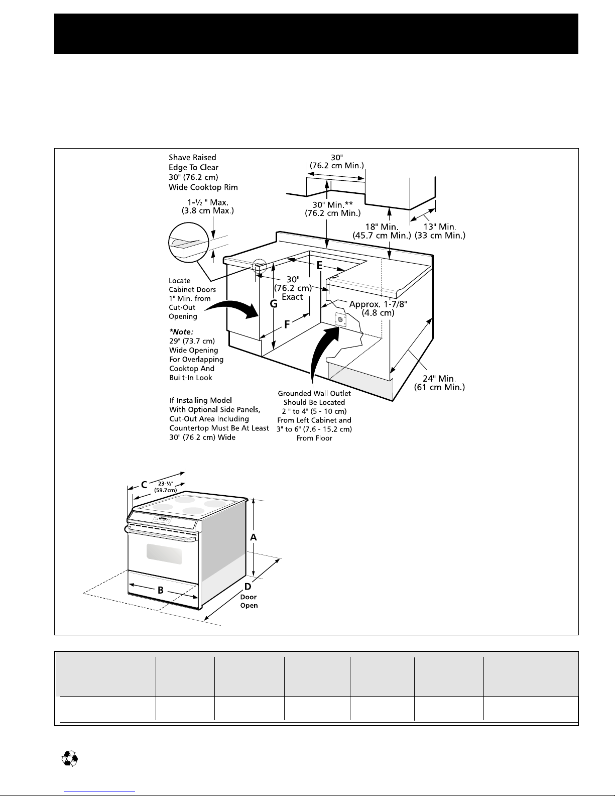
**NOTE: 24" (61 cm) minimum clearance between the cooktop
and the bottom of the cabinet when the bottom of wood or
metal cabinet is protected by not less than 1/4" (0.64 cm) flame
retardant millboard covered with not less than No. 28 MSG sheet
metal, 0.015" (0.4 mm) stainless steel, 0.024" (0.6 mm)
aluminum, or 0.020" (0.5 mm) copper.
30" (76.2 cm) minimum clearance when the cabinet is
unprotected.
C. DEPTH TO D. DEPTH E. MINIMUM F . MINIMUM G. HEIGHT
A. HEIGHT B. WIDTH FRONT OF WITH CUTOUT CUTOUT OF
RANGE DOOR OPEN WIDTH DEPTH COUNTERTOP
3
3
/
35
/
8 - 36
8" (90-92 cm) 30" (76.2 cm) 26
F. Minimum Cutout Depth is increased to 24" (61 cm) with backguard.
Recycled paper Printed in Canada P/N 318104602 (9902) Rev. F
1
/
4" (66.7 cm) 44
7
/
8" (114 cm) 29" (73.7 cm) 21
1
5
/
8" (55 cm) 36" (91.4 cm) standard
3
/
35
8"(90 cm) min
30" ELECTRIC SLIDE-IN RANGE INSTALLATION INSTRUCTIONS
Important Notes to the Installer
1. Read all instructions contained in these installation
instructions before installing range.
2. Remove all packing material from the oven
compartments before connecting the electrical supply to
the range.
3. Observe all governing codes and ordinances.
4. Be sure to leave these instructions with the consumer.
Important Note to the Consumer
Keep these instructions with your owner's guide for future
reference.
IMPORTANT SAFETY
INSTRUCTIONS
• Be sure your range is installed and grounded
properly by a qualified installer or service
technician.
• This range must be electrically grounded in
accordance with local codes or, in their absence,
with the National Electrical Code ANSI/NFPA No.
70—latest edition.
• The installation of appliances designed for
manufactured (mobile) home installation must conform
with Manufactured Home Construction and Safety
Standard, title 24CFR, part 3280 [Formerly the Federal
Standard for Mobile Home Construction and Safety,
title 24, HUD (part 280)] or when such standard is not
applicable, the Standard for Manufactured Home
Installation 1982 (Manufactured Home Sites,
Communities and Setups), ANSI Z225.1/NFPA 501Alatest edition, or with local codes.
• Make sure the wall coverings around the range
can withstand the heat generated by the range.
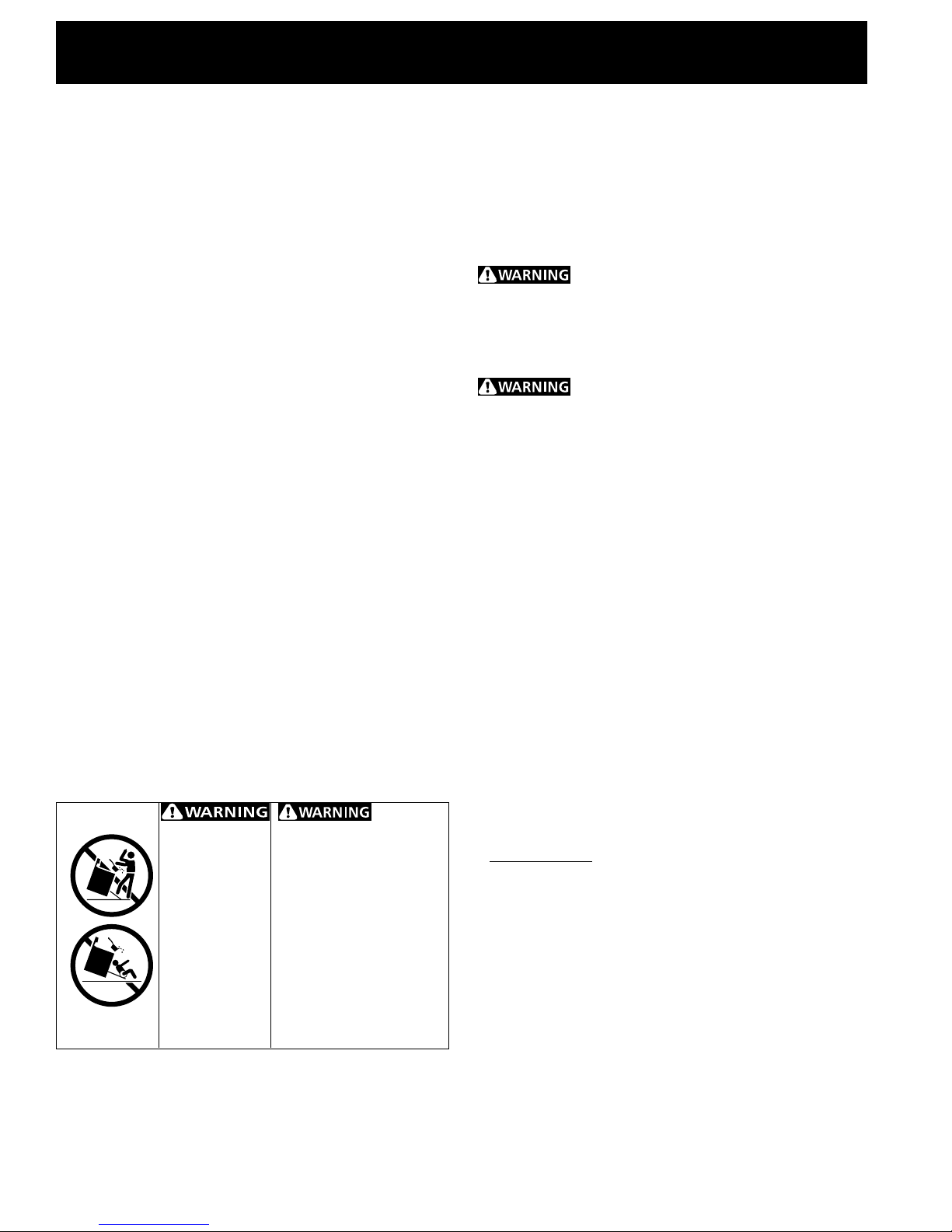
TO REDUCE
• ALL RANGES
CAN TIP.
• INJURY TO
PERSONS
COULD
RESULT.
• INSTALL ANTITIP DEVICE
PACKED WITH
RANGE.
THE RISK OF TIPPING OF
THE RANGE, THE RANGE
MUST BE SECURED BY
PROPERLY INSTALLED ANTITIP BRACKET(S) PROVIDED
WITH THE RANGE. TO
CHECK IF THE BRACKET(S)
IS INSTALLED PROPERLY,
GRASP THE TOP REAR
EDGE OF THE RANGE AND
CAREFULLY TILT IT
FORWARD TO MAKE SURE
THE RANGE IS ANCHORED.
• Before installing the range in an area covered
with linoleum or any other synthetic floor
covering, make sure the floor covering can
withstand heat at least 90°F above room
temperature without shrinking, warping or
discoloring. Do not install the range over carpeting
unless you place an insulating pad or sheet of 1/4"
thick plywood between the range and carpeting.
Never leave children alone or
unattended in the area where an appliance is in use.
As children grow, teach them the proper, safe use of all
appliances. Never leave the oven door open when the
range is unattended.
Stepping, leaning or sitting on the door
or drawer of this range can result in serious injuries
and can also cause damage to the range.
• Do not store items of interest to children in the
cabinets above the range. Children could be
seriously burned climbing on the range to reach items.
• To eliminate the need to reach over the surface
units, cabinet storage space above the units
should be avoided.
• Do not use the oven as a storage space. This
creates a potentially hazardous situation.
• Never use your range for warming or heating the
room. Prolonged use of the range without adequate
ventilation can be dangerous.
• Do not store or use gasoline or other flammable
vapors and liquids near this or any other
appliance. Explosions or fires could result.
• Reset all controls to the "off" position after using
a programmable timing operation.
FOR MODELS WITH SELF-CLEAN FEATURE:
• Remove broiler pan, food and other utensils
before self-cleaning the oven. Wipe up excess
spillage. Follow the precleaning instructions in the
Owner's Guide.
2
30" ELECTRIC SLIDE-IN RANGE INSTALLATION INSTRUCTIONS
Power Supply Cord Kit
The user is responsible for connecting the power supply
cord to the connection block located behind the back
panel access cover.
This appliance may be connected by means of
permanent "hard wiring" (flexible armored or
nonmetallic shielded copper cable), or by means of a
power supply cord kit. Only a power supply cord kit
rated at 125/250 volts minimum, 40 amperes and
marked for use with ranges shall be used. Cord must
have 3 conductors (see Figure 3).
Mobile home installation, or areas where local codes do
not permit grounding through neutral, a 4 conductor
power supply cord kit rated at 125/250 volts minimum,
40 amperes and marked for use with ranges should be
used (see Figure 4).
Terminals on ends of wires must either be closed loop or
open-end spade lugs with upturned ends. Cord must
have strain relief clamp.
Risk of fire or electrical shock may be
incurred if an incorrect size range cord kit is used,
the Installation Instructions are not followed, or
the strain relief bracket is discarded.
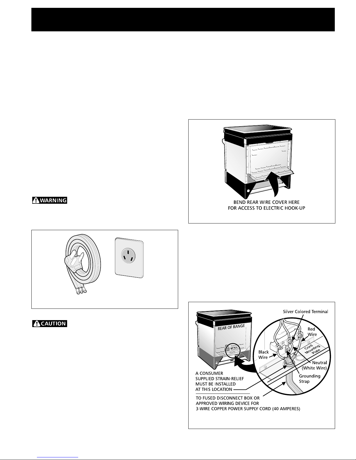
Figure 1
Electrical Connection to the Range
This appliance is manufactured with the neutral terminal
connected to the frame.
1. Three Conductor Wire Connection to Range
If local codes permit connection of the frame
grounding conductor to the neutral wire of the
copper power supply cord (see Figure 3).
A. Remove the 3 screws at the lower end of the
rear wire cover, then raise the lower end of the
rear wire cover (access cover) upward to expose
range terminal connection block (see Figure 2).
Figure 2
B. Remove the 3 loose nuts (after you removed the
rubber band) on the terminal block using 3/8"
nut driver or socket.
C. Connect the neutral of the copper power supply
cord to the center silver-colored terminal of the
terminal block, and connect the other wires to
the outer terminals. Math wires and terminals by
color (red wires connected to the right terminal,
black wires connected to the left terminal).
D. Lower the terminal cover and replace the 3
screws.
Do not loosen nuts, which secure the
factory-installed range wiring to terminal block
while connecting range. Electrical failure or loss of
electrical connection may occur.
Figure 3
3
30" ELECTRIC SLIDE-IN RANGE INSTALLATION INSTRUCTIONS
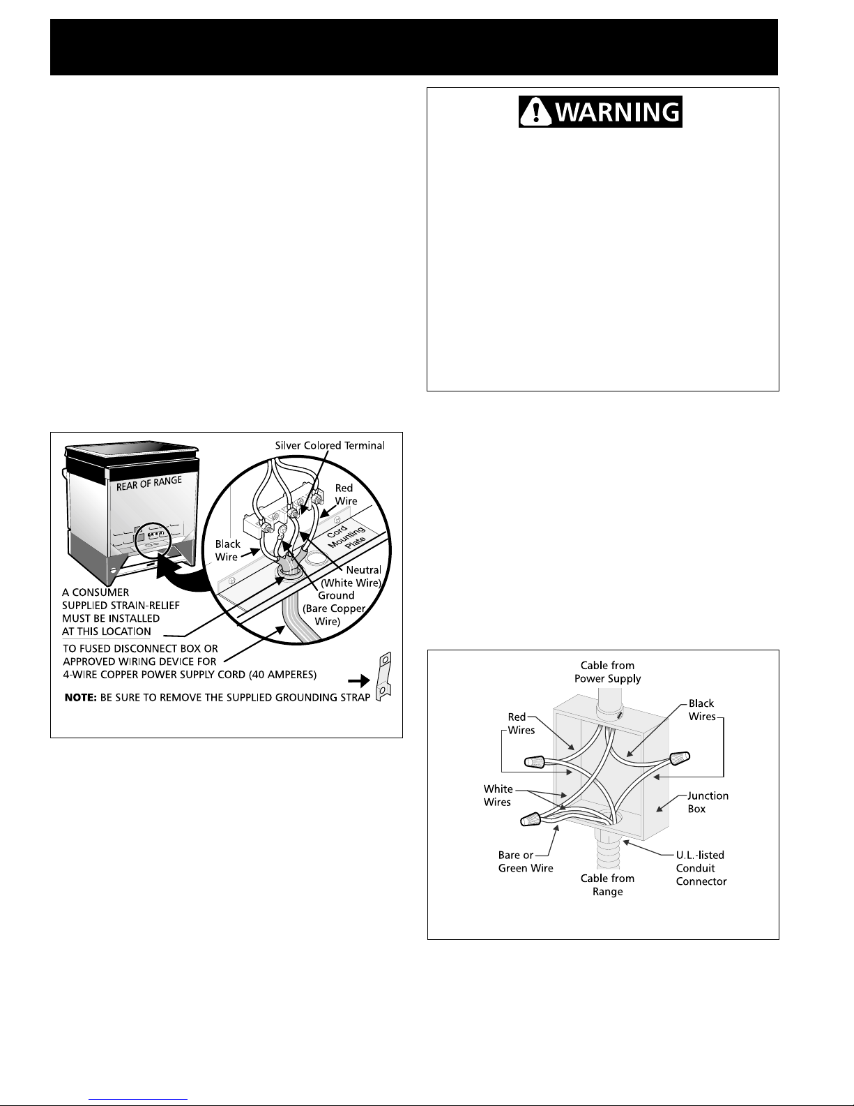
2. Four Conductor Wire Connection to Range
(mobile homes)
A. Remove the 3 screws at the lower end of the
rear wire cover, then raise the lower end of the
rear wire cover (access cover) upward to expose
range terminal connection block.
B. Remove the ground strap from the terminal
block and from the appliance frame. Retain the
ground screw.
C. Connect the ground wire (green) of the copper
power supply cord to the frame of the appliance
with the ground screw, using the hole in the
frame where the ground strap was removed (see
Figure 4).
D. Connect the neutral (white) wire of the copper
power supply cord to the center silver-colored
terminal of the terminal block, and connect the
other wires to the outer terminals.
E. Lower the terminal cover and replace the 3
screws.
Electrical Shock Hazard
• Electrical ground is required on this appliance.
• Do not connect to the electrical supply until
appliance is permanently grounded.
• Disconnect power to the junction box before
making the electrical connection.
• This appliance must be connected to a
grounded, metallic, permanent wiring system,
or a grounding connector should be connected
to the grounding terminal or wire lead on the
appliance.
Failure to do any of the above could result in a
fire, personal injury or electrical shock.
Grounding Instructions
For appliances connected to a junction box, use U.L.listed conduit connectors. Complete electrical
connection according to local codes and ordinances.
Figure 4
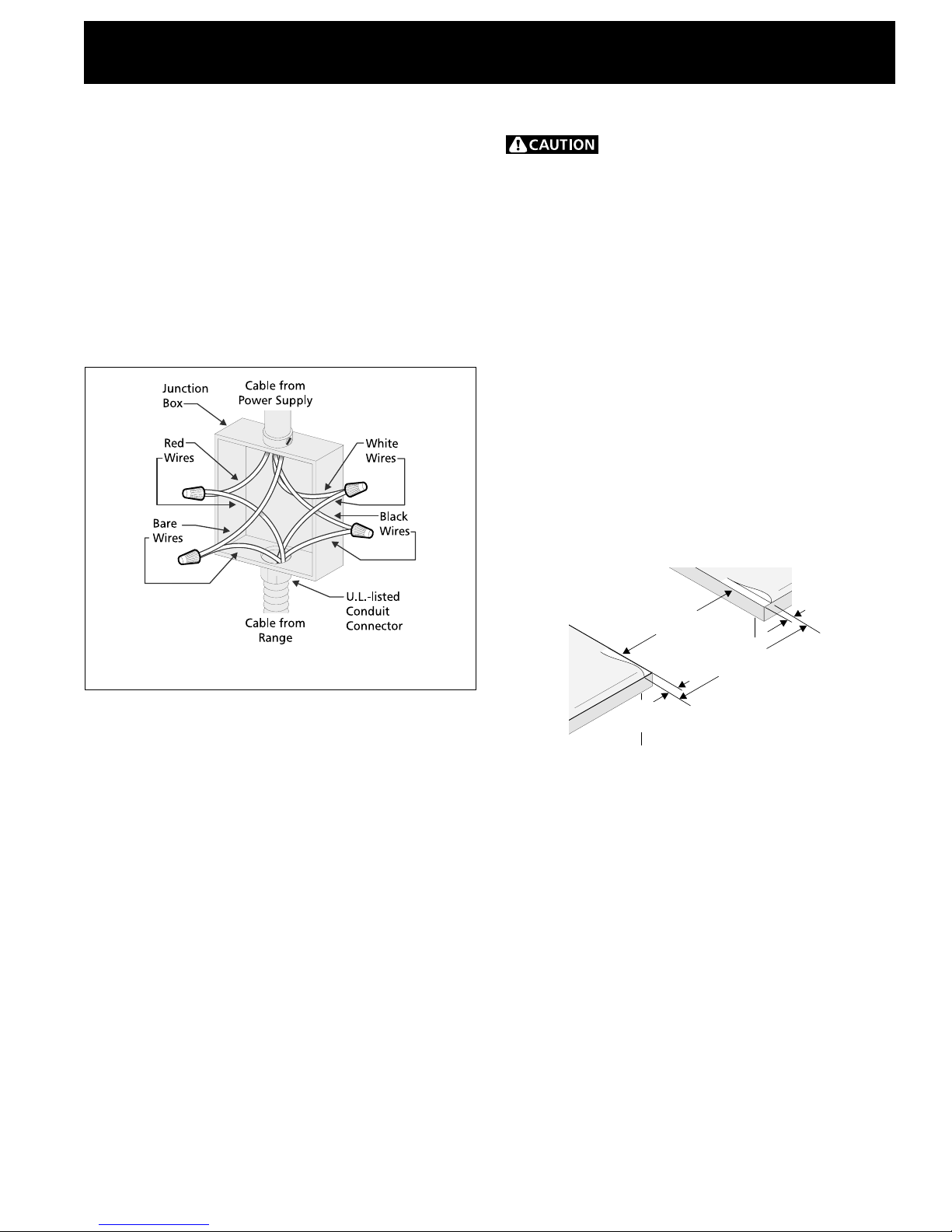
Electrical Connection to the Residence
Electrical System
The appliance should be connected directly to the fused
disconnect or circuit breaker box through flexible,
armored or nonmetallic sheathed copper cable (with
grounding wire). Locate the junction box to allow 2 to 3
feet of slack in the line so that the range can be moved
if servicing is ever necessary. Do not cut the conduit.
1. Where local codes permit connecting the
cabinet-grounding conductor to the neutral
(white) junction box wire (see Figure 5)
A. Disconnect the power supply.
B. Connect together the 3 wires: green (bare) and
white appliance cable wires and the neutral
(white) wire in the junction box.
C. Connect the 2 black wires together, then the
two red wires together.
A U.L.-listed conduit connector must be provided at
each end of the power supply cable (at the appliance
and at the junction box). Wire sizes (copper wire only)
and connections must conform with the rating of the
appliance.
Figure 5 – GROUNDED NEUTRAL
4
30" ELECTRIC SLIDE-IN RANGE INSTALLATION INSTRUCTIONS
2. Where local codes DO NOT permit, or if
connecting to a 4-wire electrical system, DO
NOT connect the cabinet-grounding conductor
to the neutral (white) junction box wire (see
Figure 6)
A. Disconnect the power supply.
B. Separate the bare copper and white appliance
cable wires.
C. Connect the white appliance cable wire to the
neutral (white) wire in the junction box.
D. Connect the 2 black wires together, then the
two red wires together.
E. Connect the bare copper grounding wire to the
grounding wire in the junction box.
Cabinet Construction
To eliminate the risk of burns or fire by
reaching over heated surface units, cabinet storage
space located above the range should be avoided. If
cabinet storage space is to be provided, the risk can be
reduced by installing a range hood that projects
horizontally a minimum of 5" (12.7 cm) beyond the
bottom of the cabinet.
Countertop Preparation
The cooktop sides of the range fit over the cutout edge
of your countertop.
If you have a square finish (flat) countertop, no
countertop preparation is required.
Formed front-edged countertops must have molded
edge shaved flat 1/4" (0.64 cm) from each front corner
of opening.
Tile countertops may need trim cut back 1/4" (0.64
cm) from each front corner and/or rounded edge
flattened.
Figure 6 – 4-WIRE ELECTRICAL SYSTEM
1/4"
(.64 cm)
1/4"
(.64 cm)
Min.
cutout
width
30.00"
(76.2 cm)
Formed or tiled countertop
trimmed 1/4" (.064cm)
back at front corners of
countertop opening.
If the countertop opening width is greater than the
minimum cutout width, adjust the 1/4" (0.64 cm)
dimension.
Countertop must be level. Place a level on the
countertop, first side to side, then front to back. If the
countertop is not level, the range will not be level. The
oven must be level for satisfactory baking results.
Cooktop sides of range fit over edges of countertop
opening.
5
 Loading...