


SERVICE DATA SHEET 318047409 (0203) Rev. B
Gas & Electric Wall Ovens with Electronic Oven Control (ES 100)
NOTICE
This service data sheet is intended for use by persons having electrical and mechanical training and a level of
knowledge of these subjects generally considered acceptable in the appliance repair trade. The manufacturer
cannot be responsible, nor assume any liability, for injury or damage of any kind arising from the use of
this data sheet.
SAFE SERVICING PRACTICES
To avoid the possibility of personal injury and/or property damage, it is important that safe servicing practices be
observed. The following are some limited examples of safe practices.
1. Do not attempt a product repair if you have any doubts as to your ability to complete it in a safe and satisfactory
manner.
2. Before servicing or moving an appliance, remove power cord from electric outlet, trip circuit
breaker to Off, or remove fuse.
3. Never interfere with the proper installation of any safety device.
4. USE ONLY REPLACEMENT PARTS CATALOGED FOR THIS APPLIANCE. SUBSTITUTIONS MAY DEFEAT COMPLIANCE
WITH SAFETY STANDARDS SET FOR HOME APPLIANCES.
5. GROUNDING: The standard color coding for safety ground wires is GREEN OR GREEN WITH YELLOW STRIPES.
Ground leads are not to be used as current carrying conductors. IT IS EXTREMELY IMPORTANT THAT THE SERVICE
TECHNICIAN REESTABLISH ALL SAFETY GROUNDS PRIOR TO COMPLETION OF SERVICE. FAILURE TO DO SO
WILL CREATE A POTENTIAL HAZARD.
6. Prior to returning the product to service, ensure that:
• All electric and gas connections are correct and secure.
• All gas connections are tested for leaks. DO NOT TEST FOR GAS LEAKS WITH A FLAME.
• All electrical leads are properly dressed and secured away from sharp edges, high-temperature components,
and moving parts.
• All uninsulated electrical terminals, connectors, heaters, etc. are adequately spaced away from all metal
parts and panels.
• All safety grounds (both internal and external) are correctly and securely reassembled.
• All panels are properly and securely reassembled.
1
ES100 ELECTRONIC OVEN CONTROL
The ES100 electronic oven control is almost identical to the current control with a few exceptions.
Bake
Broil
Timer
On/Off
Clock
Set
Clear
Off
Note: The ES100's are not field repairable.
Note: Depending on model, the size and shape of touch pads may vary (for example round instead of elliptical).
NORMAL BAKE
During a normal bake mode, the control preheats the oven by alternate bake & broil elements. When the desired
temperature is reached, the control adds top heat by cycling the broil element on for 6 to 9 seconds per minute .
The bake element is on for the remaining time of the minute. Both elements use full power when they are on but
they are never on at the same time.
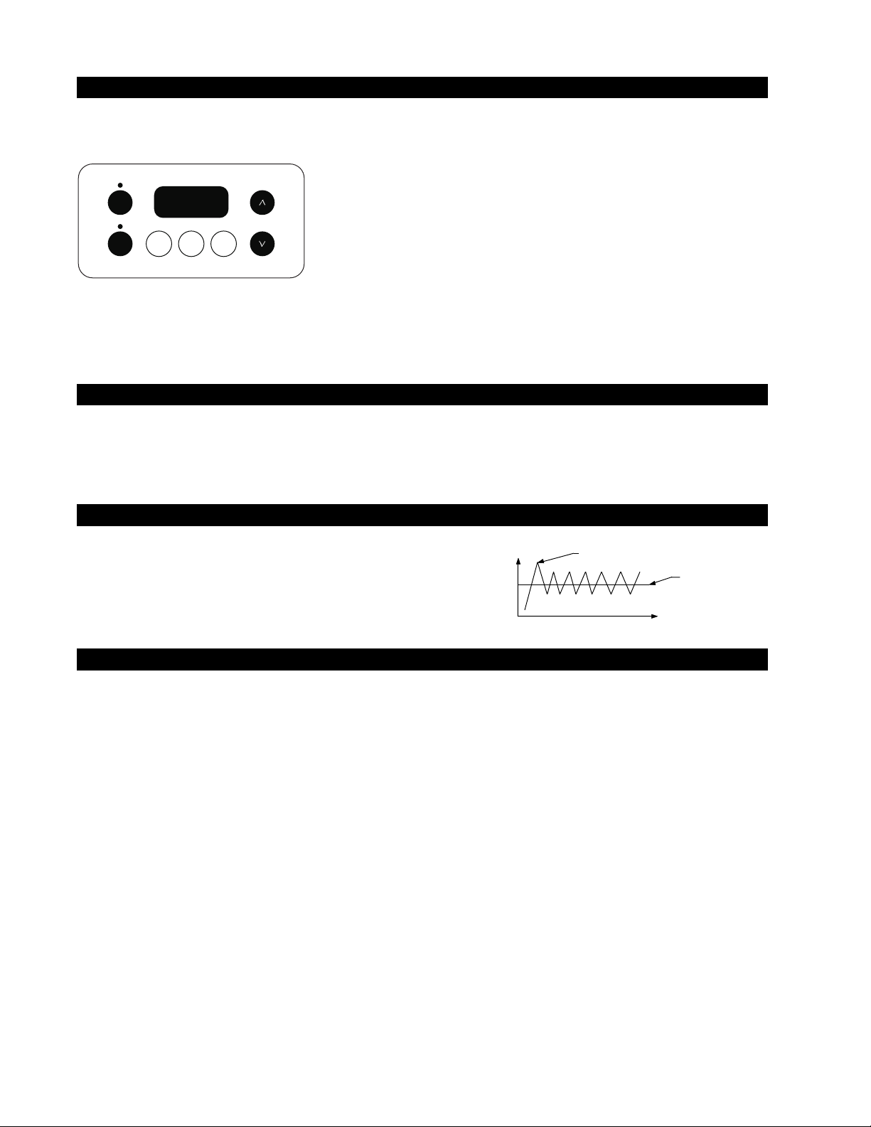
FIRST RISE
It is normal to see a temperature overshoot in the
first rise of all modes when you monitor the temperature.
T°
t (sec)
First rise overshoot
set point
OVEN CALIBRATION
Set the electronic oven control for normal baking at 350°F/176°C. Obtain an average oven temperature after a minimum
of 5 cycles. Press Cancel to end bake mode.
2

ES100 ELECTRONIC OVEN CONTROL
ELECTRONIC OVEN CONTROL FAULT CODE DESCRIPTIONS AND RTD SCALE
Note: Only two fault codes are displayed by this control “F1”and “F3”. Generally, “F1” implies a control failure,
and “F3” an oven probe problem. In all ocurrences the alarm is accompanied by a display of “F1”
Fault Code
F1
F3
Likely Failure Condition/Cause
1. Shorted keypad.
2. Control's internal checksum may
have become corrupted.
3. Control has sensed a potential
runaway oven condition. Control may
have shorted relay, RTD sensor probe
may have gone bad.
1. Open RTD sensor probe/ wiring
problem. Note: EOC may initially
display an "F1", thinking a runaway
condition exists.
2. Shorted RTD sensor probe / wiring
problem. Note: "F3" is displayed
when oven is in active mode or an
attempt to enter an active mode is
made.
Suggested Corrective Action
1. Replace EOC.
2. Disconnect power, wait 30 seconds and reapply power. If
fault returns upon power-up, replace EOC.
3. Check RTD sensor probe and replace if necessary. If oven
is overheating, disconnect power. If oven continues to
overheat when the power is reapplied, replace EOC.
Severe overheating may require the entire oven to be
replaced, should damage be extensive.
1. Check wiring in probe circuit for possible open condition.
Check RTD resistance at room temperature (compare to
probe resistance chart). If resistance does not match the
chart, replace the RTD sensor probe.
2. Check wiring in probe circuit for possible short condition.
Check RTD resistance at room temperature (compare to
probe resistance chart). If resistance does not match the
chart, replace the RTD sensor probe.
3

RTD SCALE
Temp. °F Temp. °C Resistance (ohms)
32 ± 1.9 0.0 ± 1.1 1000 ± 4.0
75 ± 2.5 23.9 ± 1.4 1091 ± 5.3
250 ± 4.4 121.1 ± 2.4 1453 ± 8.9
ELECTRICAL RATING
(Electric Models)
Kw Rating 3.5 / 2.6
240/208 V
Bake Element 2100W / 1577W
Wattage
350 ± 5.4 176.7 ± 3.0 1654 ± 10.8
450 ± 6.9 232.2 ± 3.8 1852 ± 13.5
550 ± 8.2 287.8 ± 4.6 2047 ± 15.8
650 ± 9.6 343.3 ± 5.3 2237 ± 18.5
900 ± 13.6 482.2 ± 7.6 2697 ± 24.4
CIRCUIT ANALYSIS MATRIX
Bake Broil
Function Element Element
Bake X* X*
Broil X
* Denotes broil element alternate with bake element.
Broil Element 3400W / 2554W
Wattage
Oven Temperature
Sensor
4

 Loading...