

Page 1
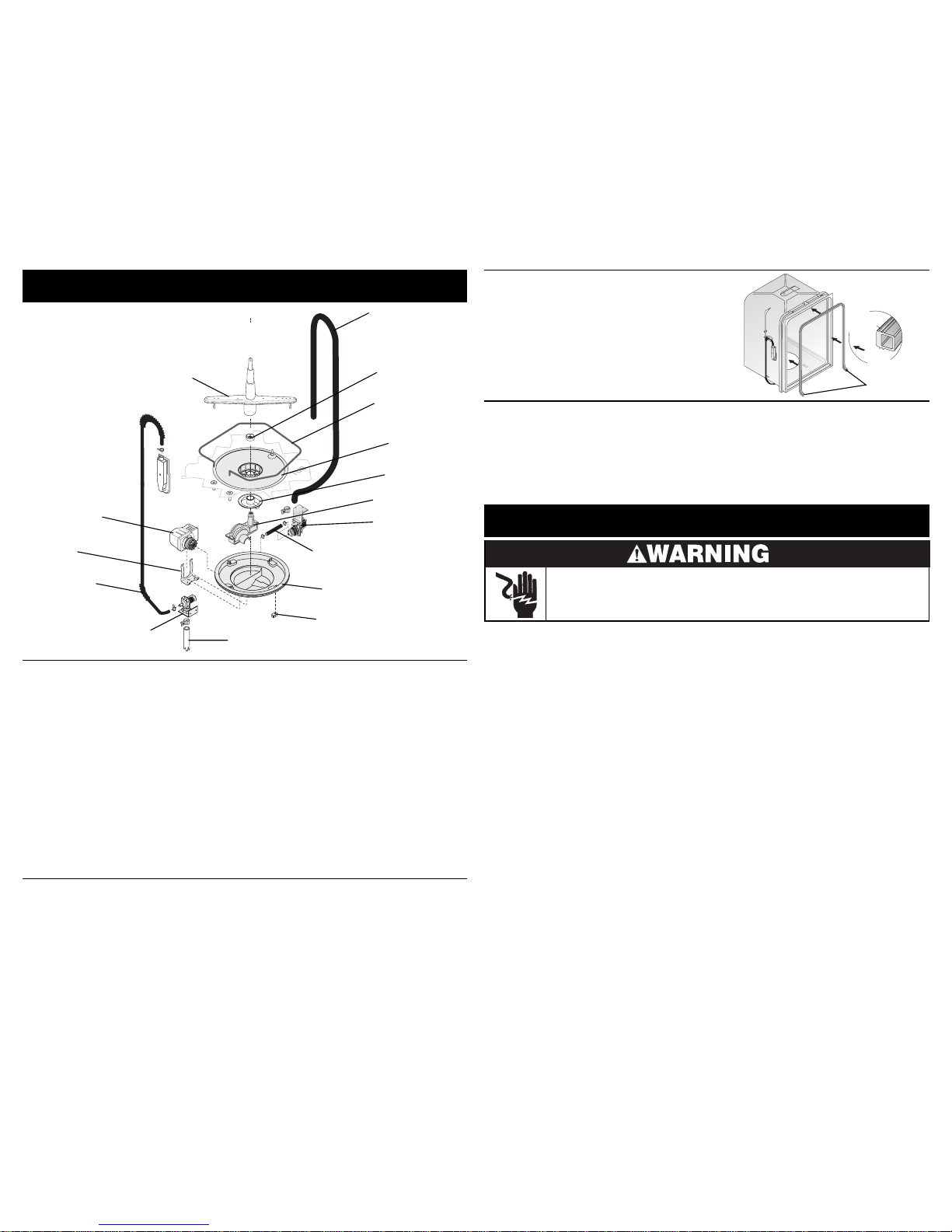
Exploded View of Wash System
011116 (MECH)
worm gear clamp to the discharge end of
the drain pump.
The drain hose must have a loop at a
minimum height of 32 inches
in order to
insure proper drainage.
The main pump can easily be removed by
disconnecting the drain pump connector
hose and the wiring harness connections
made at the circulation motor and rotating
the four sump retainers toward the middle
of the sump.
Pump Assembly
The pump assembly is driven by a
synchronous motor. Rotation is in the
counterclockwise direction at 3600 RPM.
The motor drives a pump which supplies
100 percent filtered water at a rate to
approximately 12 GPM.
Draining is accomplished by using a small
separate synchronous drain pump mounted
to the side of the sump. The drain pump is
connected to the main pump by a small
rubber hose. The drain check valve is
located at the discharge end of the drain
pump. The drain hose is attached by a
900 Watt Heater
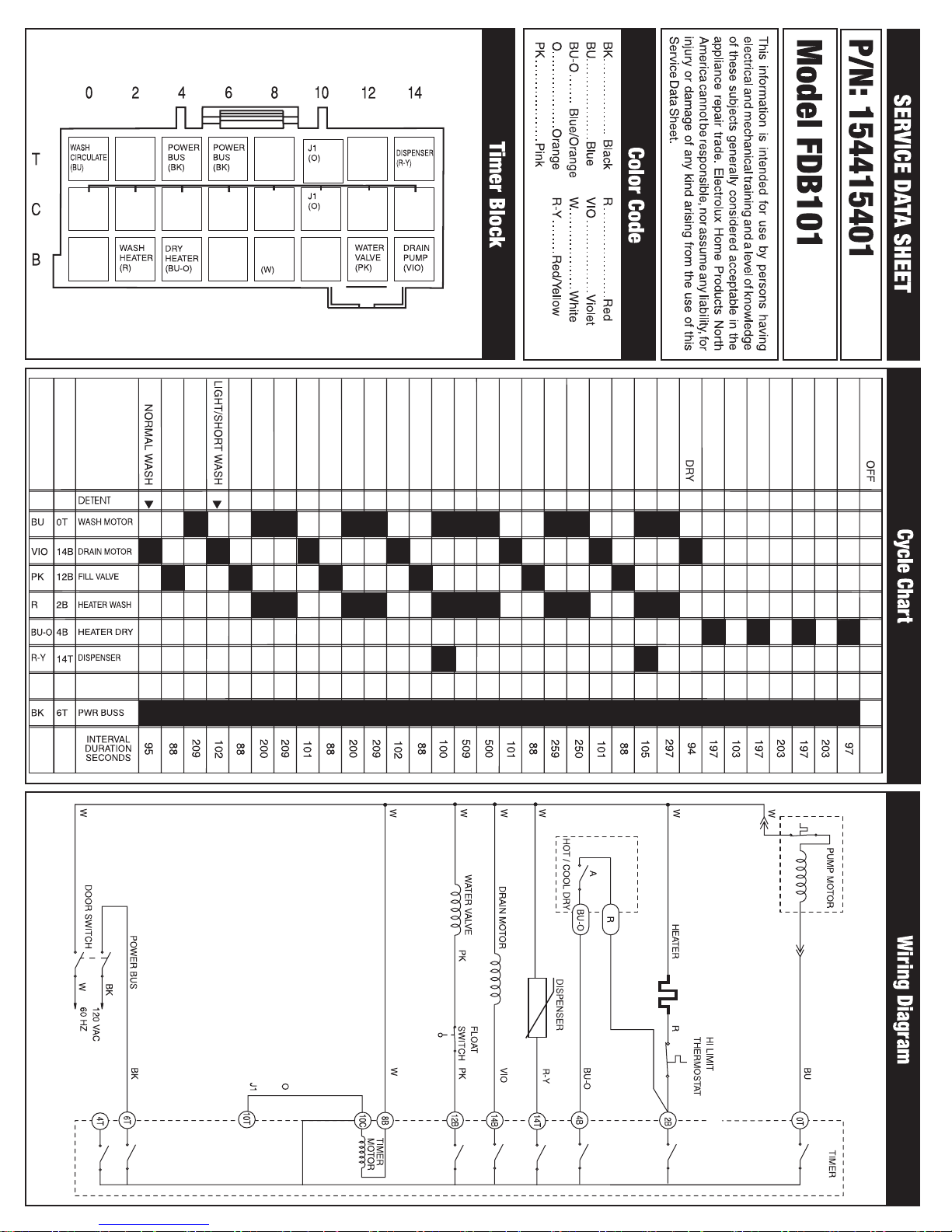
Refer to the cycle chart on the reverse side
to determine when the heater is on during
the wash cycle.
Voltage checks of the heater should be
made with the timer set in the main wash.
Drain Hose
(32" minimum
height)
Heating Element
Filter
Soil Director
Volute Cover
Drain Motor
Connector Hose and Clamps
Sump
Incoming Water Supply
Water Valve
Water Inlet
Tube
Circulation
Motor Assembly
Nut
Lower Spray Arm/Tower Assembly
Tub and Door Seal
The door seal is pressed into the tub
channel for an interference fit. Center the
gasket (marked on back) at the tub top
center and press in place without stretching
or bunching. The gasket takes a short turn
at the bottom of the tub channel before
ending at the channel end wall.
Mounting
Rib
Tub
Interior
Gasket Cross Section
Short Turn
Product Specifications
Water Supply
Minimum incoming water temperature ..............
................................................... 120°F (49°C)
Pressure (PSI) min./max. ..................... 20/120
Connection (NPT)........................................
3
/8”
Consumption (Normal Cycle)...........................
........................................... 7.2 gal., 27.3 liters
Electrical
Rating ..................................... 120 Volts, 60Hz
Separate Circuit ...... 15 amp min.- 20 amp max.
Motor (Amps).............................................. 1.1
Heater Wattage.......................................... 900
T otal Amps (load rated)............................. 10.0
Trouble Shooting Tips
Electric Shock Hazard
Check the list below each symptom. Repair or replace defective components as encountered.
Symptom. . .Dishwasher will not operate
when turned on (wait at least 90 seconds).
1. Fuse (blown or tripped).
2. 120 VAC supply wiring connection faulty.
3. Timer (contacts open or defective)
4. Motor (inoperative).
5. Door switch (open contacts).
6. Door latch not making contact with door switch.
7. Selector switch (open contacts).
Symptom. . .Motor hums but will not start or
run.
1. Motor (bad bearings or locked rotor).
2. Motor stuck due to prolonged
non-use.
Symptom. . .Motor trips out on internal thermal
overload protector.
1. Improper voltage.
2. Motor shaft binding.
3. Motor windings shorted.
4. Glass or foreign items in pump.
Symptom. . .Dishwasher runs but will not heat.
1. Heater element (open).
2. Timer defective.
3. Wiring or terminal defective.
Symptom. . .Dishwasher will not pump out.
1. Drain restricted.
2. Timer contact defective.
3. Defective drain pump.
4. Air lock in drain hose.
5. Blocked impeller.
6. Open windings.
Symptom. . .Dishwasher will not fill with water.
1. Water supply turned off.
2. Defective water inlet fill valve.
3. Check fill valve screen for obstructions.
4. Defective float switch.
5. Timer contact defective.
6. Wiring defective.
7. Float stuck in “UP” position.
Symptom. . .Timer does not advance.
1. Timer motor (stalled or open.)
2. Check timer for power to timer motor.
3. Timer shaft binding to or knob interference with
escutcheon.
Symptom. . .Dishwasher water siphons out.
1. Drain hose (high) loop too low--must be a
minimum height of 32 inches.
2. Drain line connected to a floor drain not vented.
(Install air gap at counter top.)
Disconnect electrical power at the fuse box or circuit breaker box before
adjusting or replacing components. Failure to follow this warning could
result in death or serious injury.
Motor
Bracket
Sump Retainers (4)
Page 2
 Loading...