

Page 1

All about the
Installation
of your Dryer
TABLE OF CONTENTS
Important Safety Instructions ..............................2-3
Installation Requirements .................................4-10
Installed Dryer Dimensions ..................................11
Installation Instructions ..................................12-19
Reversing Door ..............................................20-23
Accessories .........................................................24
Español ..............................................................25
137442700A (1104)
Page 2
IMPORTANT SAFETY INSTRUCTIONS
WARNING
For your safety the information in this manual must be followed to minimize the risk of fi re or explosion or to prevent
property damage, personal injury or loss of life. Do not store or use gasoline or other fl ammable vapors and liquids in
the vicinity of this or any other appliance.
WARNING - RISK OF FIRE
Read all of the following instructions before installing and using this appliance:
Destroy the carton and plastic bags after the dryer is unpacked. Children might use them for play. Cartons covered •
with rugs, bedspreads, or plastic sheets can become airtight chambers causing suffocation. Place all materials in a
garbage container or make materials inaccessible to children.
Clothes dryer installation and service must be performed by a qualifi ed installer, service agency or the gas supplier.•
Install the clothes dryer according to the manufacturer’s instructions and local codes.•
The electrical service to the dryer must conform with local codes and ordinances and the latest edition of the Na-•
tional Electrical Code, ANSI/NFPA 70, or in Canada, the Canadian electrical code C22.1 part 1.
The gas service to the dryer must conform with local codes and ordinances and the latest edition of the National •
Fuel Gas Code ANSI Z223.1, or in Canada, CAN/ACG B149.1-2000. An individual manual shut-off valve must be
installed within 6 ft (1.83 m) of the dryer in accordance with the National Fuel Gas Code, ANSI Z223.1/NFPA 54.
The dryer is designed under ANSI Z 21.5.1 or ANSI/UL 2158 - CAN/CSA C22.2 No. 112 (latest editions) for HOME •
USE only. This dryer is not recommended for commercial applications such as restaurants, beauty salons, etc.
Do not install a clothes dryer with fl exible plastic venting material. Flexible venting materials are known to collapse, •
be easily crushed and trap lint. These conditions will obstruct clothes dryer airfl ow and increase the risk of fi re.
The instructions in this manual and all other literature included with this dryer are not meant to cover every pos-•
sible condition and situation that may occur. Good safe practice and caution MUST be applied when installing,
operating and maintaining any appliance.
WHAT TO DO IF YOU SMELL GAS:
Do not try to light any appliance.•
Do not touch any electrical switch; do not use any phone in •
your building.
Clear the room, building or area of all occupants.•
Immediately call your gas supplier from a neighbor’s phone. •
Follow the gas supplier’s instructions.
If you cannot reach your gas supplier, call the fi re department.•
Pre-Installation Requirements
Tools and materials needed for installation:
Adjustable pliers•
Phillips, straight, & square bit •
screwdrivers
Adjustable wrench•
Pipe wrench for gas supply (gas •
dryer)
LP-resistant thread tape (for natu-•
ral gas or LP supply, gas dryer)
To avoid back or other injury, have more than
one person move or lift the appliance.
Save these instructions for
Carpenter’s level•
External vent hood•
4-inch (102 mm), rigid metal or •
semi-rigid metal exhaust duct work
3-wire or 4-wire 240 volt cord kit •
(electric dryer)
4 in. (102 mm) clamp•
CAUTION
EXCESSIVE WEIGHT HAZARD
future reference.
Gas line shutoff valve (gas dryer)•
½ NPT union fl are adapters (x2) •
and fl exible gas supply line (gas
dryer)
Metal foil tape (not duct tape)•
2
Page 3
IMPORTANT SAFETY INSTRUCTIONS
WARNING
Please read all instructions before using this dryer.
Recognize safety symbols, words and
labels
Safety items throughout this manual are labeled with
a WARNING or CAUTION based on the risk type as
described below:
Defi nitions
This is the safety alert symbol. It is used to alert
you to potential personal injury hazards. Obey all safety
messages that follow this symbol to avoid possible injury
or death.
DANGER
DANGER indicates an imminently hazardous situation
which, if not avoided, will result in death or serious
injury.
Installation Checklist
Exhaust Venting
Free-fl owing, clear of lint buildup
4 inch (102 mm) rigid or semi-rigid ducting of
minimal length and turns
NO foil or plastic venting material
Approved vent hood exhausted to outdoors
Leveling
Dryer is level, side-to-side and front-to-back
Cabinet is setting solid on all corners
Gas Supply (Gas Dryer)
Manual shutoff valve present in supply
All connections sealed with approved sealer
and wrench tight
Conversion kit for LP system
Gas supply turned on
No leaks present at all connections -
check with soapy water, NEVER check with
fl ame
WARNING
WARNING indicates a potentially hazardous situation
which, if not avoided, could result in death or serious
injury.
CAUTION
CAUTION indicates a potentially hazardous situation
which, if not avoided, may result in minor or moderate
injury.
IMPORTANT
IMPORTANT indicates installation, operation or
maintenance information which is important but not
hazard-related.
240v Electric Supply (Electric Dryer)
Approved NEMA 10-30R or 14-30R service
cord with all screws tight on terminal block
Approved strain relief installed
Terminal access cover installed before initial
operation
Door Reversal
Follow detailed instructions in this guide
Test hinge and latch for function
Electrical Power
House power turned on
Dryer plugged in
Final Checks
Installation Instructions
Care Guide
Door latches and drum tumbles when cycle
starts
Registration card sent in
read thoroughly
and
Use and
3
Page 4
INSTALLATION REQUIREMENTS
NOTE
Í
Because of potentially inconsistent voltage capabilities, the use of this dryer with power created by gas powered
generators, solar powered generators, wind powered generators or any other generator other than the local utility
company is not recommended.
Electrical requirements for electric dryer
CIRCUIT - Individual 30 amp. branch circuit fused with 30 amp. time delay fuses or circuit breakers. Use separately
fused circuits for washer and dryer. DO NOT operate a washer and a dryer on the same circuit.
POWER SUPPLY - 3-wire or 4-wire, 240 volt, single phase, 60 Hz, Alternating Current.
IMPORTANT
This dryer is internally grounded to neutral unless it was manufactured for sale in Canada.
Only a 4-conductor cord shall be used when the appliance is installed in a location where grounding through
the neutral conductor is prohibited. Grounding through the neutral link is prohibited for: (1) new branch circuit
installations, (2) mobile homes, (3) recreational vehicles, and (4) areas where local codes do not permit grounding
through the neutral.
OUTLET RECEPTACLE - NEMA 10-30R or NEMA 14-30R receptacle to be located so the power supply cor d is accessible
when the dryer is in the installed position.
GROUNDING CONNECTION - See “Grounding requirements” in Electrical Installation section.
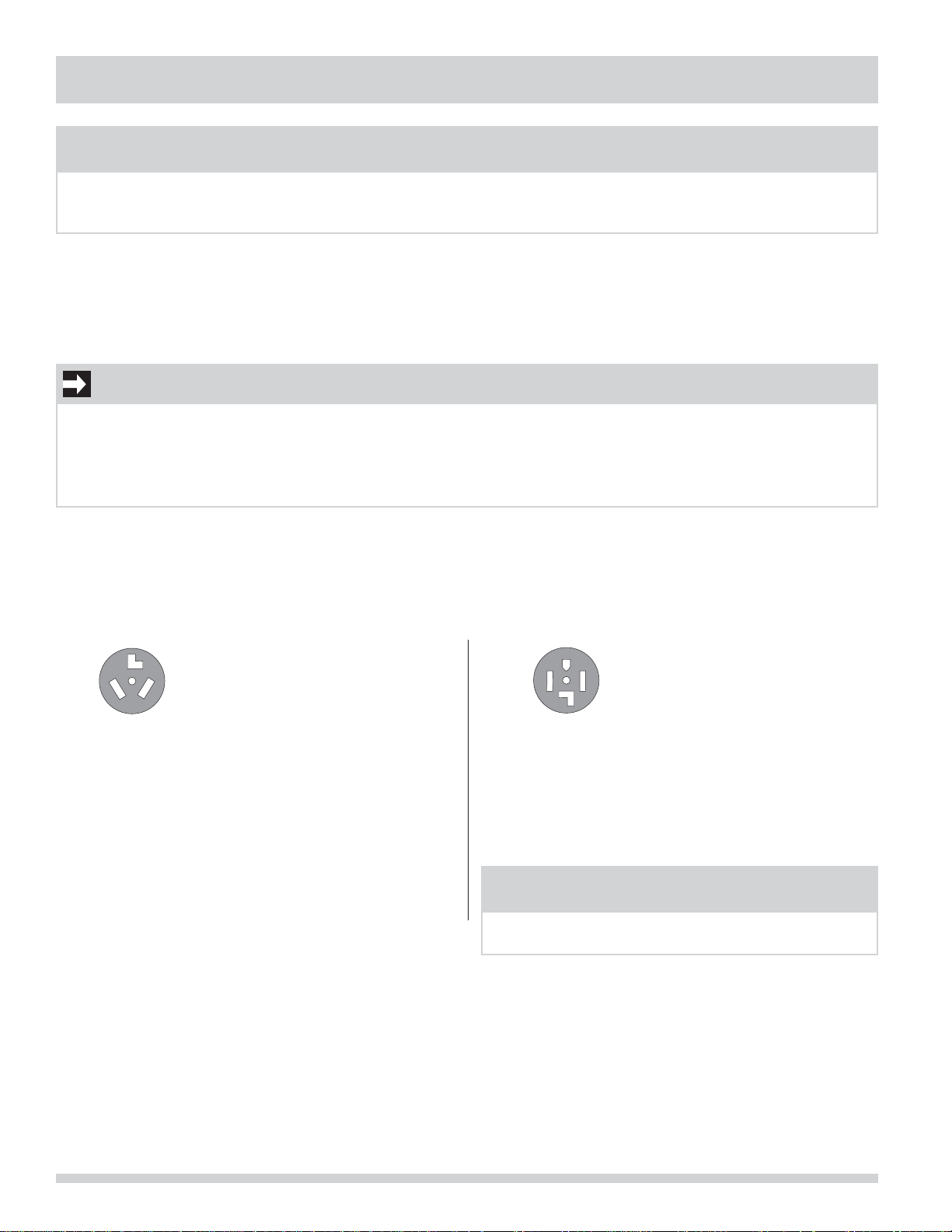
3-WIRE POWER SUPPLY CORD KIT (not supplied)
3-wire receptacle
(NEMA type 10-30R)
The dryer MUST employ a 3-conductor power
supply cord NEMA 10-30 type SRDT rated at 240
volt AC minimum, 30 amp, with 3 open end spade
lug connectors with upturned ends or closed
loop connectors and marked for use with clothes
dryers. For 3-wire cord connection instructions see
ELECTRICAL CONNECTIONS FOR A 3-WIRE SYSTEM.
4-WIRE POWER SUPPLY CORD KIT (not supplied)
4-wire receptacle
(NEMA type 14-30R)
The dryer MUST employ a 4-conductor power supply
cord NEMA 14-30 type SRDT or ST (as required) rated
at 240 volt AC minimum, 30 amp, with 4 open end
spade lug connectors with upturned ends or closed
loop connectors and marked for use with clothes
dryers. For 4-wire cord connection instructions see
ELECTRICAL CONNECTIONS FOR A 4-WIRE SYSTEM.
NOTE
Í
Dryers manufactured for sale in Canada have factoryinstalled, 4-wire power supply cord (NEMA 14-30R).
4
Page 5
INSTALLATION REQUIREMENTS
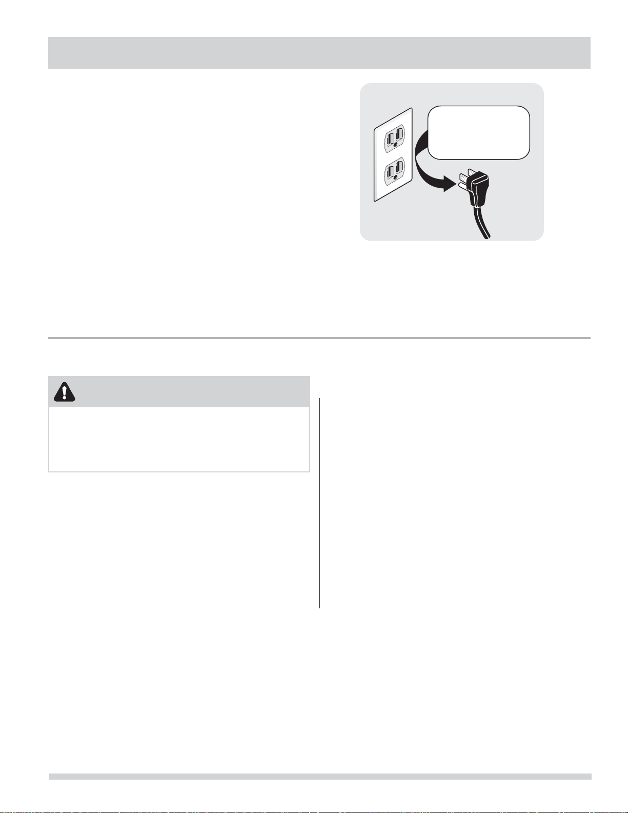
Grounding type
ll receptacle
wer cord with
3-prong grgr
ounded plug
Do not,
under
y cir
cumstances,
cut,
removeve,
or b
ypass the
ounding pr
ong.
Electrical requirements for gas dryer
CIRCUIT - Individual, properly polarized and grounded
15 amp. branch circuit fused with 15 amp. time delay
fuse or circuit breaker.
POWER SUPPLY - 2-wire, with ground, 120 volt, single
phase, 60 Hz, Alternating Current.
POWER SUPPLY CORD - The dryer is equipped with a 120
volt 3-wire power cord.
GROUNDING CONNECTION - See “Grounding
requirements” in Electrical Installation section.
Gas supply requirements
WARNING
EXPLOSION HAZARD
Uncoated copper tubing will corrode when subjected
to natural gas, causing gas leaks. Use ONLY black iron,
stainless steel, or plastic-coated brass piping for gas
supply.
1 Installation MUST conform with local codes, or in
the absence of local codes, with the National Fuel
Gas Code, ANSI Z223.1 (latest edition).
2 The gas supply line should be 1/2 inch (1.27 cm)
pipe.
3 If codes allow, fl exible metal tubing may be used
to connect your dryer to the gas supply line. The
tubing MUST be constructed of stainless steel or
plastic-coated brass.
Grounding type
wawall receptacl
Do not,
under
anany cir
cumstances,
cut,
remo
or b
ypass th
grgrounding pr
PoPower cord with
3-prong
4 The gas supply line MUST have an individual
shutoff valve installed in accordance with the
B149.1, Natural Gas and Propane Installation Code.
5 A 1/8 inch (0.32 cm) N.P.T. plugged tapping,
accessible for test gauge connection, MUST be
installed immediately upstream of the gas supply
connection to the dryer.
6 The dryer MUST be disconnected from the gas
supply piping system during any pressure testing
of the gas supply piping system at test pressures in
excess of 1/2 psig (3.45 kPa).
7 The dryer MUST be isolated from the gas supply
piping system during any pressure testing of the
gas supply piping system at test pressures equal to
or less than 1/2 psig (3.45 kPa).
8 Connections for the gas supply must comply with
the Standard for Connectors for Gas Appliances,
ANSI Z21.24.
ounded plug
ong.
5
Page 6
INSTALLATION REQUIREMENTS
Exhaust system requirements
Use only 4 inch (102 mm) diameter rigid or fl exible metal
duct and approved vent hood which has a swing-out
damper(s) that open when the dryer is in operation.
When the dryer stops, the dampers automatically close to
prevent drafts and the entrance of insects and rodents.
To avoid restricting the outlet, maintain a minimum of 12
inches (30.5 cm) clearance between the vent hood and
the ground or any other obstruction.
WARNING
FIRE HAZARD
Failure to follow these instructions can create excessive
drying times and fi re hazards.
The following are specifi c requirements for
proper and safe operation of your dryer.
Correct Incorrect
WARNING
FIRE HAZARD
Do not install a clothes dryer with fl exible plastic or
metal foil venting materials. Flexible venting materials
are known to collapse, be easily crushed and trap lint.
These conditions will obstruct clothes dryer airfl ow and
increase the risk of fi re.
If your present system is made up of plastic duct or
metal foil duct, replace it with a rigid or semi-rigid metal
duct. Also, ensure the present duct is free of any lint prior
to installing dryer duct.
Correct Incorrect
6
Page 7
INSTALLATION REQUIREMENTS
Exhaust system requirements, continued
WARNING
FIRE HAZARD
A clothes dryer must be exhausted outdoors. Do not
exhaust dryer into a chimney, a wall, a ceiling, an attic,
a crawl space or any concealed space of a building. A
clothes dryer produces combustible lint. If the dryer is
not exhausted outdoors, some fi ne lint will be expelled
into the laundry area. An accumulation of lint in any
area of the home can create a health and fi re hazard.
The dryer must be connected to an exhaust outdoors.
Regularly inspect the outdoor exhaust opening and
remove any accumulation of lint around the outdoor
exhaust opening and in the surrounding area.
WARNING
FIRE HAZARD
Do not allow combustible materials (for example: •
clothing, draperies/curtains, paper) to come in
contact with exhaust system. The dryer MUST NOT
be exhausted into a chimney, a wall, a ceiling,
or any concealed space of a building which can
accumulate lint, resulting in a fi re hazard.
Do not screen the exhaust ends of the vent system, •
or use any screws, rivets or other fasteners that
extend into the duct to assemble the exhaust
system. Lint can become caught in the screen, on
the screws or rivets, clogging the duct work and
creating a fi re hazard as well as increasing drying
times. Use an approved vent hood to terminate the
duct outdoors, and seal all joints with metal foil duct
tape. All male duct pipe fi ttings MUST be installed
downstream with the fl ow of air.
WARNING
FIRE HAZARD
Exceeding the length of duct pipe or number of elbows
allowed in the “MAXIMUM LENGTH” charts can cause
an accumulation of lint in the exhaust system. Plugging
the system could create a fi re hazard, as well as
increase drying times.
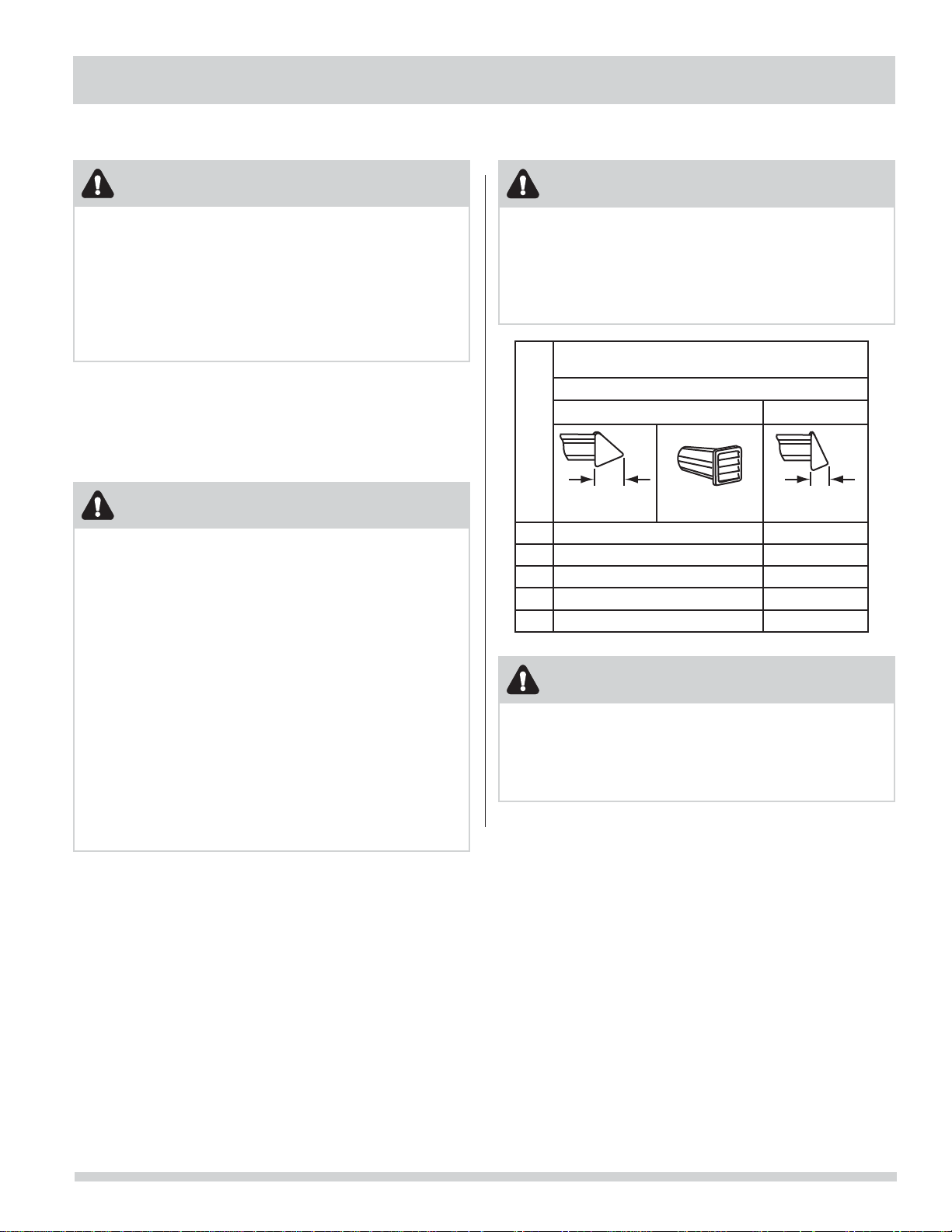
MAXIMUM LENGTH
Number of 90° turns
0 64 ft. (19.5 m) 48 ft. (14.6 m)
1 52 ft. (15.9 m) 40 ft. (12.2 m)
2 44 ft. (13.5 m) 32 ft. (9.8 m)
3 36 ft. (11 m) 24 ft. (7.3 m)
4 28 ft. (9.5 m) 16 ft. (4.9 m)
of 4” (102mm) Rigid Metal Duct
VENT HOOD TYPE
(Preferred)
4”
(102mm) louvered
2.5”
(6.35cm)
WARNING
FIRE HAZARD
Do not install fl exible plastic or fl exible foil venting •
material.
If installing semi-rigid venting, do not exceed 8 ft. •
(2.4 m) duct length.
7
Page 8
INSTALLATION REQUIREMENTS
Exhaust system requirements, continued
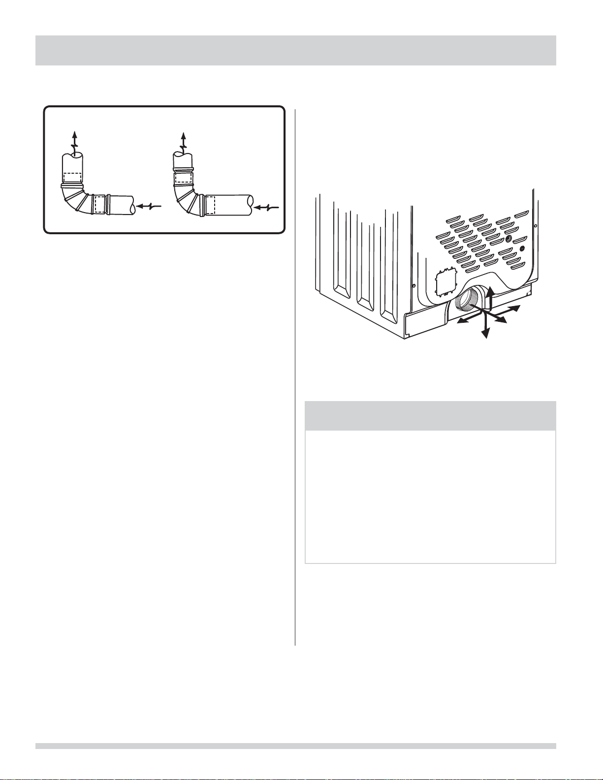
Install male fi ttings in correct direction:
CORRECT
In installations where the exhaust system is not described
in the charts, the following method must be used to
determine if the exhaust system is acceptable:
1 Connect an inclined or digital manometer between
the dryer and the point the exhaust connects to the
dryer.
2 Set the dryer timer and temperature to air fl uff
(cool down) and start the dryer.
3 Read the measurement on the manometer.
4 The system back pressure MUST NOT be higher
than 0.75 inches of water column. If the
system back pressure is less than 0.75 inches of
water column, the system is acceptable. If the
manometer reading is higher than .075 inches of
water column, the system is too restrictive and the
installation is unacceptable.
Although vertical orientation of the exhaust system is
acceptable, certain extenuating circumstances could
affect the performance of the dryer:
Only the rigid metal duct work should be used.•
Venting vertically through a roof may expose the •
exhaust system to down drafts causing an increase
in vent restriction.
Running the exhaust system through an •
uninsulated area may cause condensation and
faster accumulation of lint.
Compression or crimping of the exhaust system will •
cause an increase in vent restriction.
The exhaust system should be inspected and •
cleaned a minimum of every 18 months with
normal usage. The more the dryer is used, the
more often you should check the exhaust system
and vent hood for proper operation.
INCORRECT
Exhaust direction
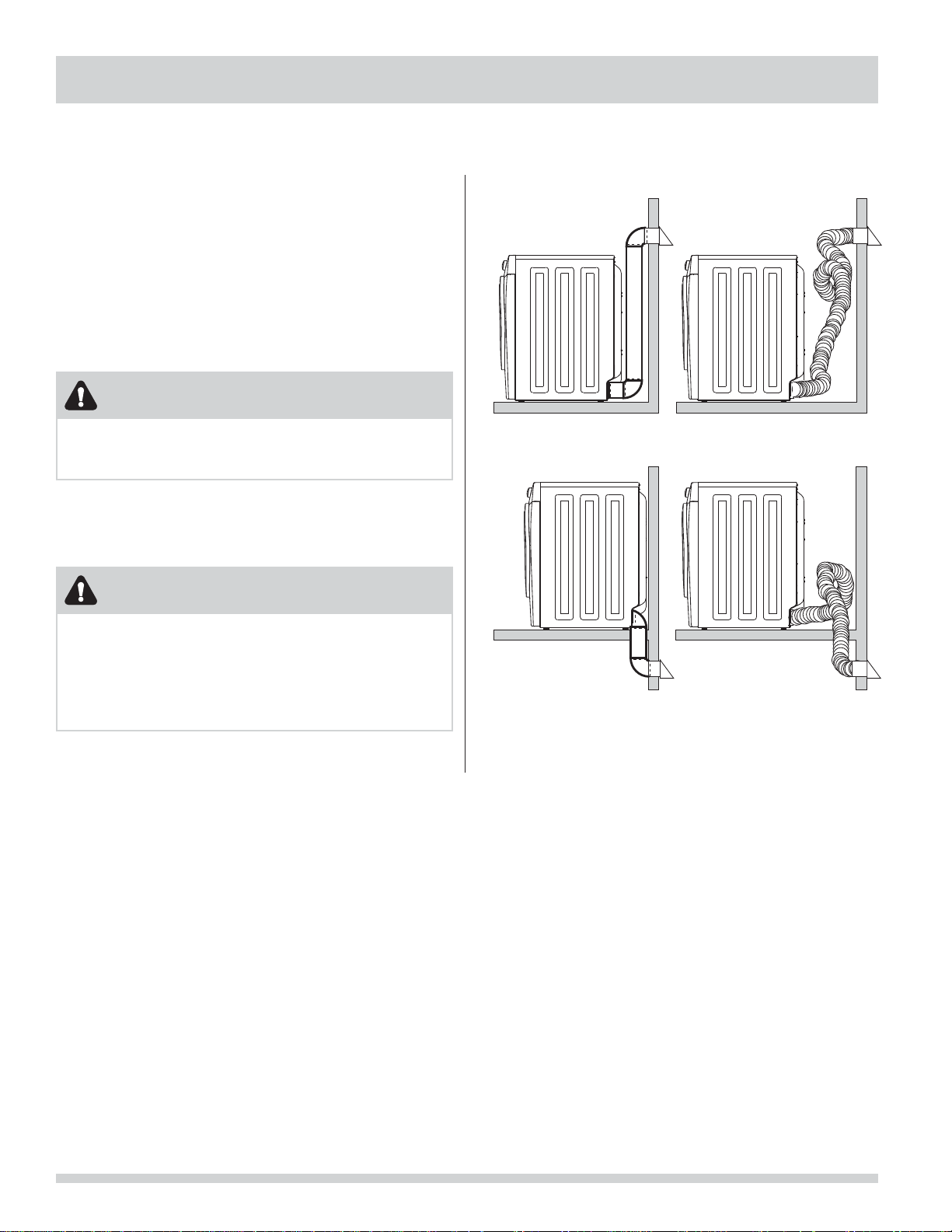
Directional exhausting can be accomplished by installing
a quick-turn 90° dryer vent elbow directly to exhaust
outlet of dryer. Dryer vent elbows are available through
your local parts distributor or hardware store.
See also CLEARANCE REQUIREMENTS on the next page.
NOTE
Í
Use of 90° quick-turn elbow required to meet minimum
installation depth of free-standing dryer:
Straight back venting allows for 0” (0 cm) installation.•
Venting right with 90° elbow allows for 0.75” (2 cm) •
installation.
Venting downward with 90° elbow allows for 0.75” (2 •
cm) installation.
Venting left with short, straight adapter and 90° •
elbow allows for 3.75” (9.5 cm) installation.
Venting upward with short, straight adapter and 90° •
elbow allows for 4” (10.5 cm) installation.
8
Page 9
INSTALLATION REQUIREMENTS
Manufactured or mobile home installation
1 Installation MUST conform to current Manufactured
Home Construction & Safety Standard, Title 24
CFR, Part 32-80 (formerly the Federal Standard
for Mobile Home Construction and Safety, Title 24,
HUD Part 280) or Standard CAN/CSAZ240 MH.
2 Dryer MUST be exhausted outside (outdoors, not
beneath the mobile home) using metal ducting
that will not support combustion. Metal ducting
must be 4 inches (10.16 cm) in diameter with no
obstructions. Rigid metal duct is preferred.
3 If dryer is exhausted through the fl oor and area
beneath the mobile home is enclosed, the exhaust
Clearance requirements
WARNING
EXPLOSION HAZARD
Do not install the dryer where gasoline or other
fl ammables are kept or stored. If the dryer is installed
in a garage, it must be a minimum of 18 inches (45.7
cm) above the fl oor. Failure to do so can result in
death, explosion, fi re or burns.
system MUST terminate outside the enclosure with
the termination securely fastened to the mobile
home structure.
4 Refer to previous sections in this guide for other
important exhaust venting system requirements.
5 When installing a gas dryer into a mobile home, a
provision must be made for outside make up air.
This provision is to be not less than twice the area
of the dryer exhaust outlet.
6 Installer MUST anchor this (1) dryer or (2) dryer
mounted on pedestal to the fl oor with approved
Mobile Home Installation Kit - P/N 137067200.
IMPORTANT
DO NOT INSTALL YOUR DRYER:
1 In an area exposed to dripping water or outside
weather conditions.
2 In an area where it will come in contact with
curtains, drapes, or anything that will obstruct
the fl ow of combustion and ventilation air.
3 On carpet. Floor MUST be solid with a maximum
slope of 1 inch (2.54 cm).
9
Page 10
INSTALLATION REQUIREMENTS
Clearance requirements, continued
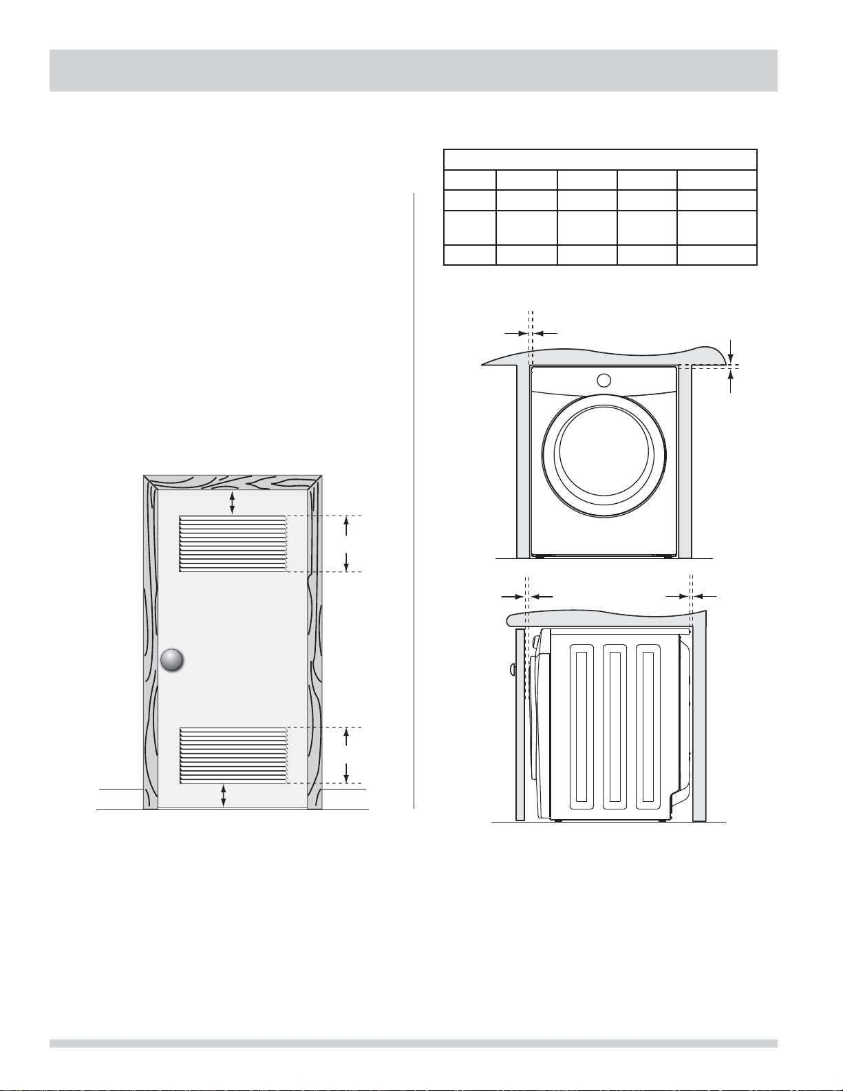
Installation in a Recess or Closet
1 A dryer installed in a bedroom, bathroom, recess or
closet, MUST be exhausted outdoors.
2 No other fuel burning appliance shall be installed in
the same closet as the gas dryer.
3 Your dryer needs the space around it for proper
ventilation.
DO NOT install your dryer in a closet with a solid door.
4 Closet door ventilation required: A minimum
of 120 square inches (774.2 cm²) of opening,
equally divided at the top and bottom of the
door, is required. Openings should be located 3
inches (7.6 cm) from bottom and top of door.
Openings are required to be unobstructed when a
door is installed. A louvered door with equivalent
air openings for the full length of the door is
acceptable.
3”
(7.6cm)
60 sq. in.
(387.1cm²)
MINIMUM INSTALLATION CLEARANCES - Inches (cm)
SIDES REAR TOP FRONT
Alcove 0” (0 cm) 0” (0 cm)* 0” (0 cm) n/a
Under-
Counter
0” (0 cm) 0” (0 cm)* 0” (0 cm) n/a
Closet 0” (0 cm) 0” (0 cm)* 0” (0 cm) 1” (2.54 cm)
Dryer must be vented straight back to achieve *
0” (0 cm) rear installation.
0”
(0cm)
0”
(0cm)
3”
(7.6cm)
closet door
60 sq. in.
(387.1cm²)
1”
(2.54cm)
0”
(0cm)
10
Page 11
51.4” (131cm)
to clear open door
30.3” (77cm)*
to front of closed door
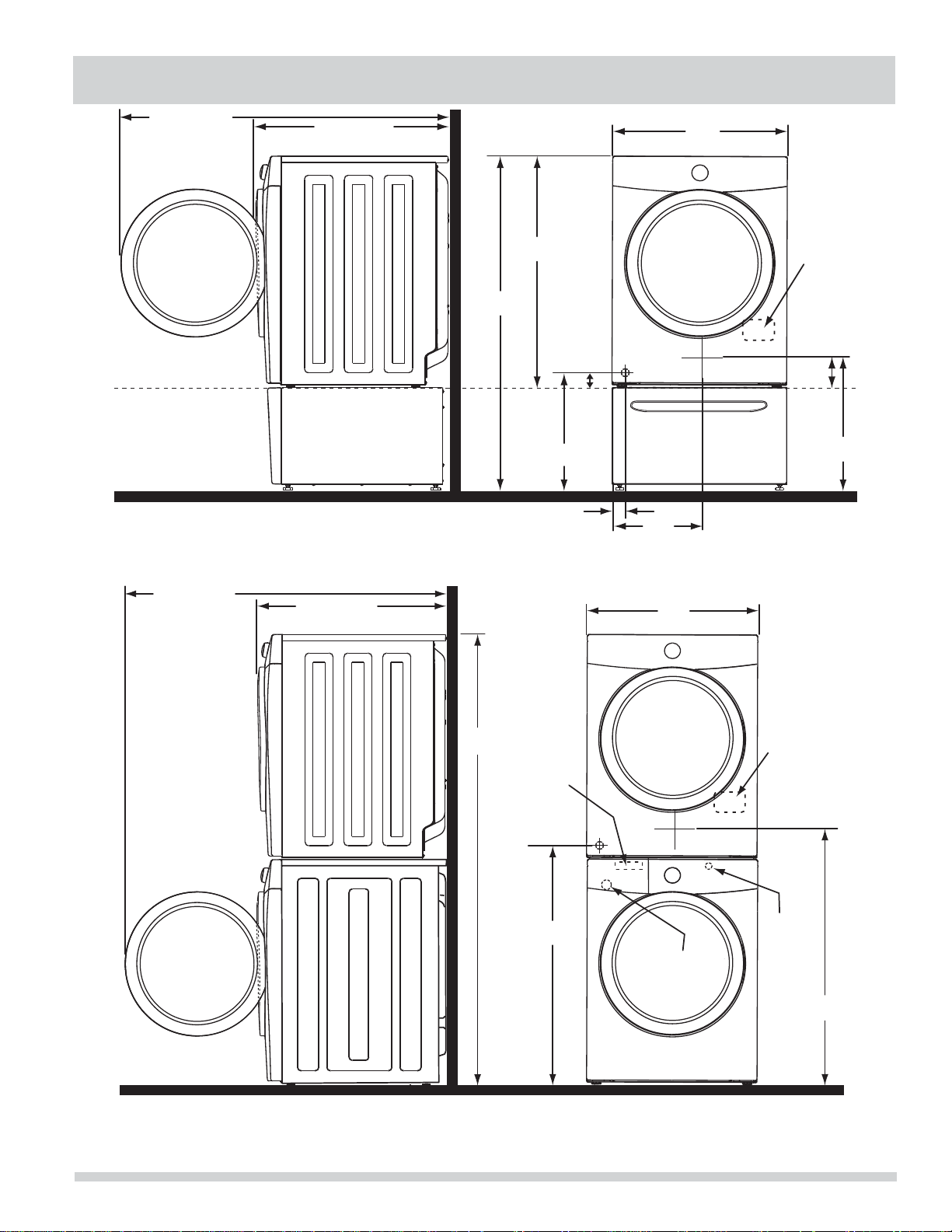
INSTALLED DIMENSIONS
27.0”
(68.5cm)
freestand dryer
on fl oor
fl oor line
dryer mounted on
optional pedestal
fl oor line
* To obtain these minimal depth dimensions, dryer must be vented straight back. Using a quick-turn 90°
elbow (right or down on freestanding dryer) adds approximately 0.75 in. (2.0 cm) to installation depth.
Upward venting of exhaust on pedestal-mounted or freestanding dryer adds approximately 4 in. (10.2 cm) to
installation depth. Leftward venting on pedestal-mounted or freestanding dryer adds approximately 3.75 in.
(9.5 cm) to installation depth. Downward venting of exhaust on pedestal-mounted dryer adds approximately
2.25 in. (5.7 cm) to installation depth.
51.4” (131cm)
to clear open door
30.3” (77cm)*
to front of closed door
51.25”
(130cm)
36.0”
(91.5cm)
gas supply
pipe on rear
of gas unit
16.9”
(43cm)
3.75”
(9.5cm)
1.6”
(4cm)
13.50”
(34.5cm)
to center of rear vent
27.0”
(68.5cm)
electrical
supply on
rear of unit
centerline
height for
rear vent
3.7”
(9.5cm)
19.0”
(48cm)
electrical
71.5”
(182cm)
water supply
connection on
1
rear of unit
gas supply
pipe on rear
of gas unit
37”
(94cm)
drain hose on
3
rear of unit
* To obtain these minimal depth dimensions, dryer must be vented straight back. Using a quick-turn 90° elbow (right) adds approximately 0.75 in. (2 cm) to installation depth. Upward venting of exhaust on stacked
dryer adds approximately 4 in. (10.2 cm) to installation depth. Downward venting of exhaust on stacked dryer adds approximately 2.25 in. (6.5 cm) to installation depth. Leftward venting of exhaust on stacked dryer
adds approximately 3.75 in. (9.5 cm) to installation depth.
1
Hot and cold inlet hose length approximately 43 inches (109cm)
2
Power supply cord length approximately 60 inches (152.5cm).
3
Drain hose length approximately 52 inches (132cm).
supply on
rear of unit
centerline
height for
rear vent
power cord on
2
rear of unit
39”
(99cm)
11
Page 12
INSTALLATION INSTRUCTIONS
Electrical installation
The following are specifi c requirements for proper and
safe electrical installation of your dryer. Failure to follow
these instructions can create electrical shock and/or a fi re
hazard.
WARNING
ELECTRICAL SHOCK HAZARD
This appliance MUST be properly grounded. •
Electrical shock can result if the dryer is not properly
grounded. Follow the instructions in this manual for
proper grounding.
Do not use an extension cord with this dryer. Some •
extension cords are not designed to withstand the
amounts of electrical current this dryer utilizes
and can melt, creating electrical shock and/
or fi re hazard. Locate the dryer within reach of
the receptacle for the length power cord to be
purchased, allowing some slack in the cord. Refer to
the pre-installation requirements in this manual for
the proper power cord to be purchased.
WARNING
ELECTRICAL SHOCK HAZARD
A U.L.-approved strain relief must be installed onto •
power cord. If the strain relief is not attached, the
cord can be pulled out of the dryer and can be cut
by any movement of the cord, resulting in electrical
shock.
Do not use an aluminum wired receptacle with a •
copper wired power cord and plug (or vice versa).
A chemical reaction occurs between copper and
aluminum and can cause electrical shorts. The
proper wiring and receptacle is a copper wired
power cord with a copper wired receptacle.
NOTE
Í
Dryers operating on 208 volt power supply will have
longer drying times than dryers operating on 240 volt
power supply.
Grounding requirements - Electric dryer (USA)
WARNING
ELECTRICAL SHOCK HAZARD
Improper connection of the equipment grounding
conductor can result in a risk of electrical shock. Check
with a licensed electrician if you are in doubt as to
whether the appliance is properly grounded.
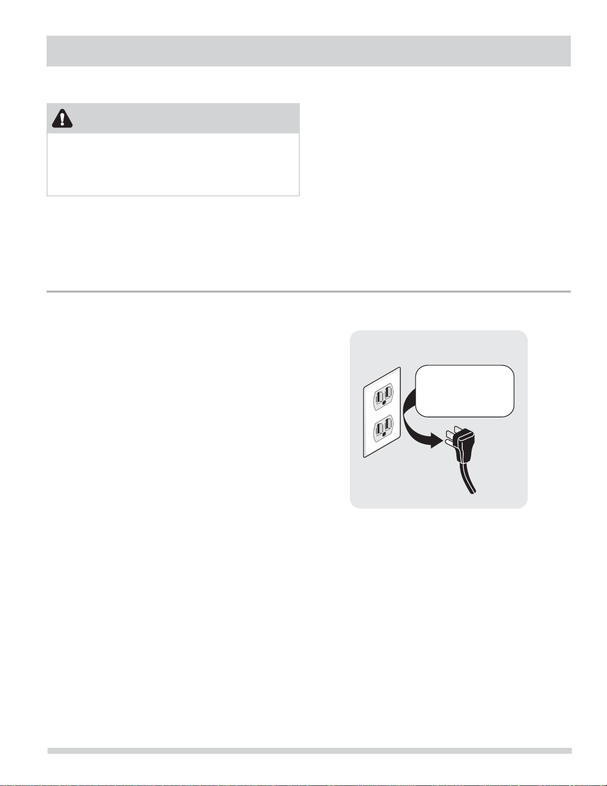
For a grounded, cord-connected dryer:
1 The dryer MUST be grounded. In the event of a
malfunction or breakdown, grounding will reduce
the risk of electrical shock by a path of least
resistance for electrical current.
2 After you purchase and install a 3 wire or 4 wire
power supply cord having an equipment-grounding
conductor and a grounding plug that matches your
wiring system, the plug MUST be plugged into
an appropriate, copper wired receptacle that is
properly installed and grounded in accordance with
all local codes and ordinances. If in doubt, call a
licensed electrician.
3 DO NOT modify the plug you’ve installed on this
appliance. If it will not fi t the outlet, have a proper
outlet installed by a qualifi ed electrician.
For a permanently connected dryer:
1 The dryer MUST be connected to a grounded
metal, permanent wiring system; or an equipment
grounding conductor must be run with the circuit
conductors and connected to the equipmentgrounding terminal or lead on the appliance.
12
Page 13
Grounding type
ll receptacle
wer cord with
3-prong grgr
ounded plug
Do not,
under
y cir
cumstances,
cut,
removeve,
or b
ypass the
ounding pr
ong.
INSTALLATION INSTRUCTIONS
Grounding requirements - Electric dryer (Canada)
WARNING
ELECTRICAL SHOCK HAZARD
Improper connection of the equipment grounding
conductor can result in a risk of electrical shock. Check
with a licensed electrician if you are in doubt as to
whether the appliance is properly grounded.
For a grounded, cord-connected dryer:
1 The dryer MUST be grounded. In the event of a
malfunction or breakdown, grounding will reduce
the risk of electrical shock by a path of least
resistance for electrical current.
2 Since your dryer is equipped with a power supply
cord having an equipment-grounding conductor
and a grounding plug, the plug must be plugged
into an appropriate outlet that is properly installed
and grounded in accordance with all local codes
and ordinances. If in doubt, call a licensed
electrician.
3 DO NOT modify the plug provided with this
appliance. If it will not fi t the outlet, have a proper
outlet installed by a qualifi ed electrician.
Grounding requirements - Gas dryer (USA and Canada)
1 The dryer is equipped with a three-prong
(grounding) plug for your protection against shock
hazard and should be plugged directly into a
properly grounded three-prong receptacle.
2 The plug must be plugged into an appropriate
outlet that is properly installed and grounded in
accordance with all local codes and ordinances. If
in doubt, call a licensed electrician.
3 DO NOT modify the plug provided with this
appliance. If it will not fi t the outlet, have a proper
outlet installed by a qualifi ed electrician.
Grounding type
wawall receptacl
Do not,
under
anany cir
cumstances,
cut,
remo
or b
ypass th
grgrounding pr
ong.
PoPower cord with
3-prong
ounded plug
13
Page 14
INSTALLATION INSTRUCTIONS
Gas connection
1 Remove the shipping cap from gas pipe at the rear
of the dryer.
IMPORTANT
DO NOT connect the dryer to L.P. gas service without
converting the gas valve. An L.P. conversion kit must be
installed by a qualifi ed gas technician.
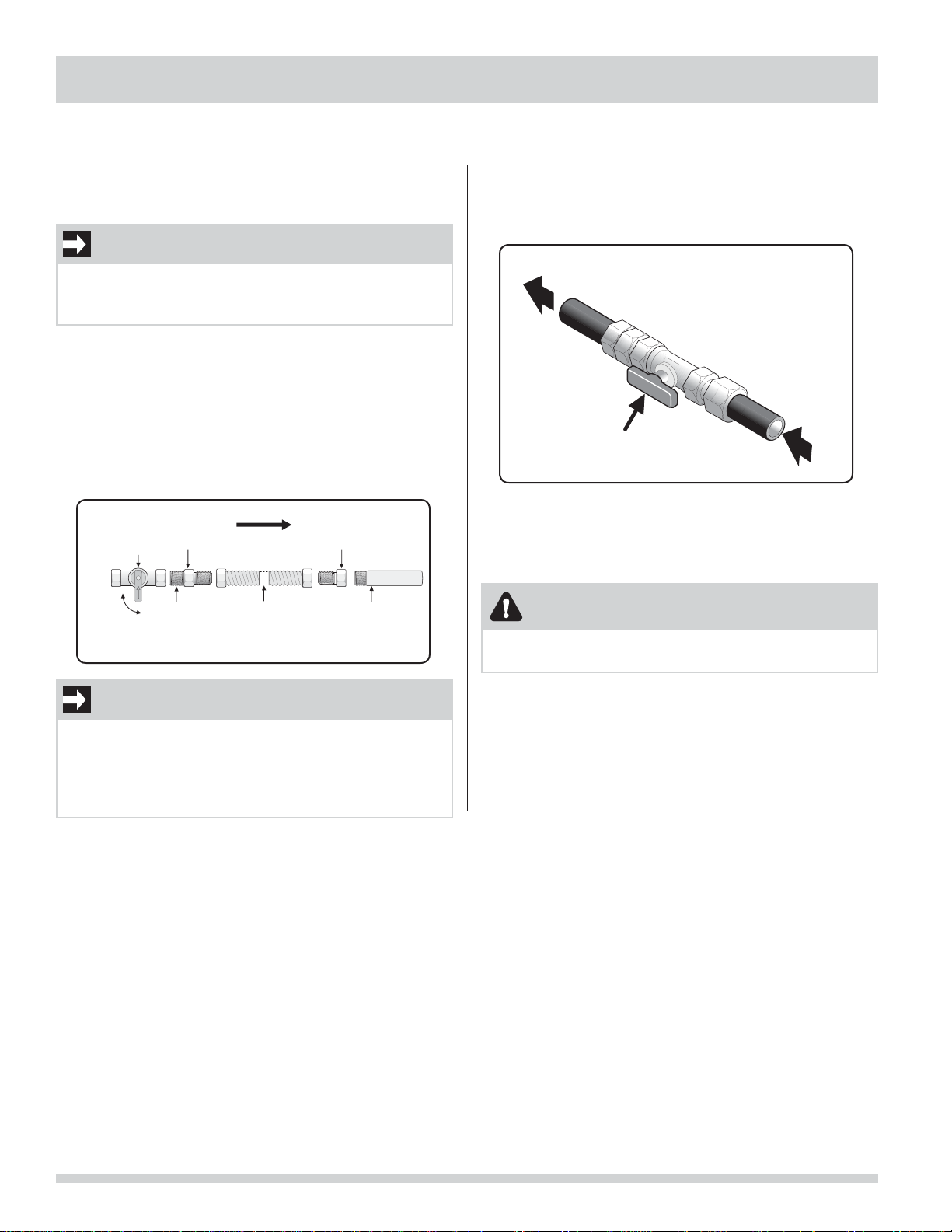
2 Connect a 1/2 inch (1.27 cm) I.D. semi-rigid or
approved pipe from gas supply line to the 3/8 inch
(0.96 cm) pipe located on the back of the dryer.
Use a 1/2 inch to 3/8 inch (1.27 cm to 0.96 cm)
reducer for the connection. Apply an approved
thread sealer that is resistant to the corrosive
action of liquefi ed gases on all pipe connections.
Closed
Manual
Shuto
Valve
Open
Flare
Union
All connections must be wrench-tightened
elppiN
GAS FLOW
Flexible
Connector
Flare
Union
Inlet Pipe on
Back of Dryer
3 Open the shutoff valve in the gas supply line to
allow gas to fl ow through the pipe. Wait a few
minutes for gas to move through the gas line.
to dryer
from gas supply
Shuto Valve Open position
4 Check for gas system leaks with a manometer. If a
manometer is not available, test all connections by
brushing on a soapy water solution.
WARNING
EXPLOSION HAZARD
NEVER test for gas leaks with an open fl ame.
IMPORTANT
The supply line must be equipped with an approved
manual shutoff valve. This valve should be located in
the same room as the dryer and should be in a location
that allows ease of opening and closing. Do not block
access to the gas shutoff valve.
14
Page 15
Water connection (Steam Model only)
WATER SUPPLY REQUIREMENTS
Cold water faucet MUST be installed within 42 inches
(107 cm) of your dryer’s water inlet. The faucet MUST be
3/4 inch (1.9 cm) with threading for laundry hose connection. Water pressure MUST be between 30 and 120
psi. Your water department can advise you of your water
pressure.
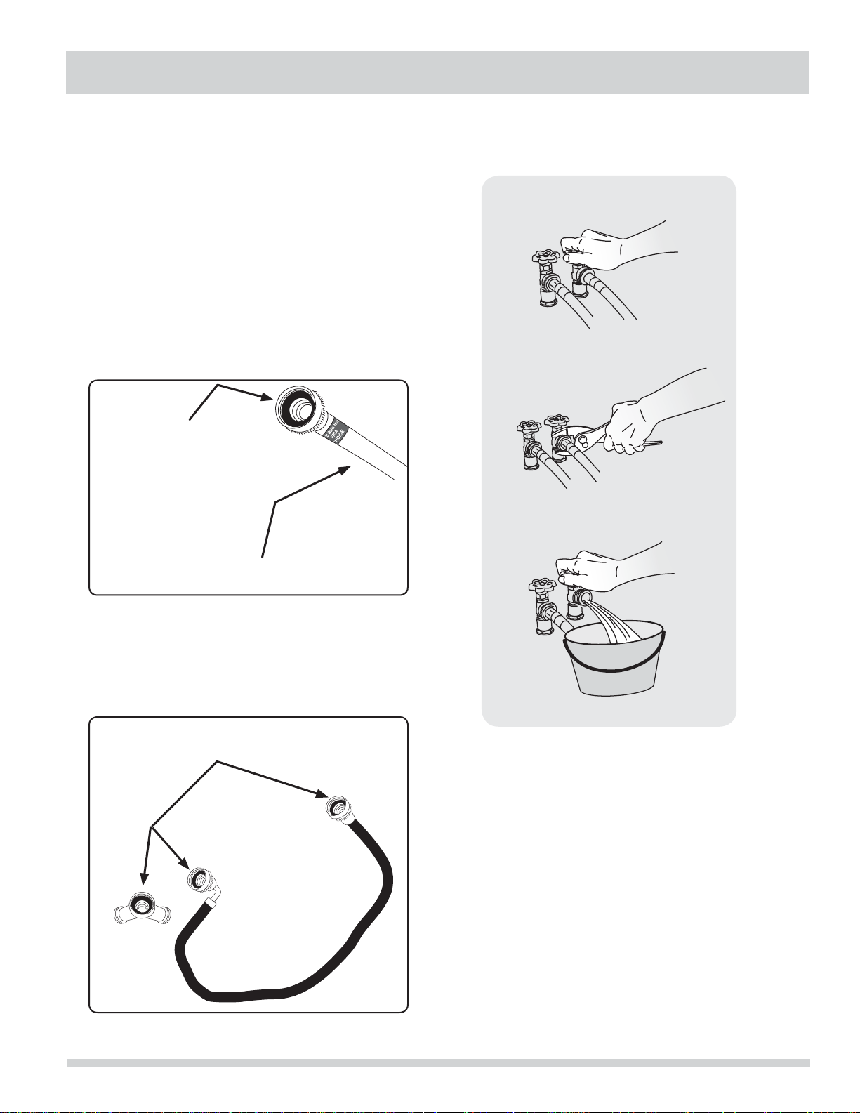
1 Turn off COLD water supply to washer.
2 Remove COLD inlet hose from COLD water supply
and inspect for rubber washer. Replace washer if it
is torn or worn out.
RUBBER WASHER
MUST BE PRESENT
AND UNDAMAGED
INSTALLATION INSTRUCTIONS
COLD INLET HOSE
TO WASHER
3 Momentarily turn on COLD supply and run some
water into a bucket or container to clear any
contaminants in the line.
4 Remove hose kit from dryer drum and inspect hose
couplings for proper placement of rubber washers.
RUBBER WASHERS
MUST BE PRESENT
15
Page 16
INSTALLATION INSTRUCTIONS
Water connection, continued (Steam Model only)
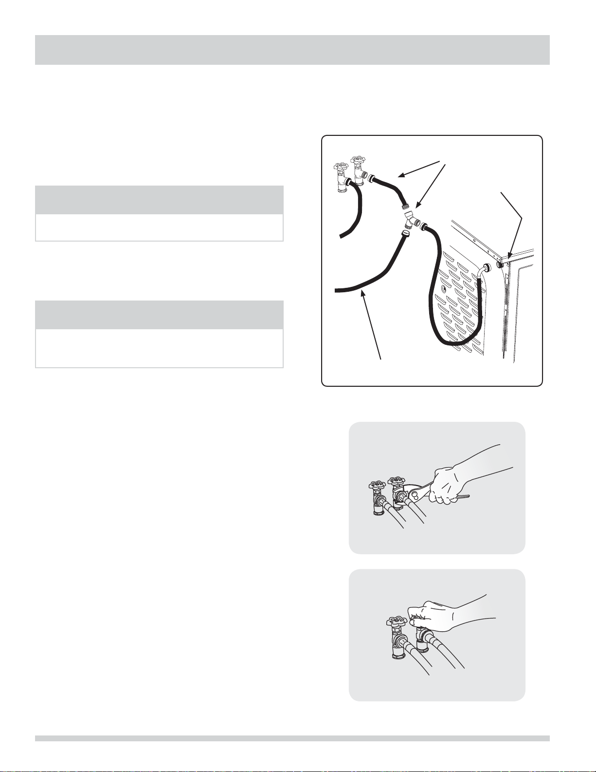
5 If your installation has room for the COLD water
supply to accept the “Y” connector directly, thread
the “Y” connector to the COLD water supply and
snug it by hand; then tighten it another 2/3 turn
with pliers.
NOTE
Í
If you were able to install the “Y” connector directly to
the COLD water supply, please skip to step 8.
6 If there is not room to install the “Y” connector
directly, thread a short extension hose on to the
COLD water supply and snug it by hand; then
tighten it another 2/3 turn with pliers.
NOTE
Í
Short extension available from your local hardware
supplier. Extension hose must meet qualifi cations for
use in laundry installation.
7 Thread the “Y” connector to the short extension
hose and snug it by hand; then tighten it another
2/3 turn with pliers.
8 Connect the COLD inlet hose for the washer to the
“Y” connector and snug it by hand; then tighten it
another 2/3 turn with pliers.
9 Connect the straight end of the long hose from the
kit to the other outlet on the “Y” connector and
snug it by hand. Connect the hose’s 90° coupling to
the brass water inlet on the back of the dryer and
snug it by hand. Tighten each connection of the
dryer inlet hose another 2/3 turn with pliers.
10 Turn on the water and check for leaks at all
connections.
COLD WATER SUPPLY
HOSE TO WASHER
*Laundry hose extension not included with dryer.
DIRECT CONNECTION
OR WITH EXTENSION*
WATER INLET
ON DRYER
16
Page 17

INSTALLATION INSTRUCTIONS
Internal ground
(GREEN screw)
Install
UL-approved
strain relief here
Terminal screw
recovery slot
Line 1
(BRASS terminal)
Neutral
(SILVER terminal)
Line 2
(BRASS terminal)
Access cover
screw
Terminal
block
Neutral
(center wire)
30 AMP
NEMA 10-30
DO NOT remove
internal ground in
a 3-wire system!!
Neutral
terminal
Electrical connection (non-Canada) - 3 wire cord
3-wire receptacle
(NEMA type 10-30R)
30 AMP
NEMA 10-30
WARNING
ELECTRICAL SHOCK HAZARD
Failure to disconnect power source before servicing
could result in personal injury or even death.
1 Turn off power supply to outlet.
2 Remove the screw securing the terminal block
access cover in the lower corner on the back of the
dryer.
3 Install a UL-approved strain relief according to the
power cord/strain relief manufacturer’s instructions
in the power cord entry hole below the access
panel. At this time, the strain relief should be
loosely in place.
4 Thread an UNPLUGGED, UL-approved, 30 amp.
power cord, NEMA 10-30 type SRDT, through the
strain relief.
5 Attach the power cord neutral (center wire)
conductor to the SILVER colored center terminal on
the terminal block. Tighten the screw securely.
6 Attach the remaining two power cord outer
conductors to the outer, BRASS colored terminals
on the terminal block. Tighten both screws
securely.
WARNING
NOTE
Í
If a terminal screw falls during cord installation, it can
be retrieved in the terminal screw recovery slot below
the access panel.
Neutral
(center wire)
Access cover
screw
Terminal
block
Line 2
(BRASS terminal)
Neutral
(SILVER terminal)
Line 1
(BRASS terminal)
Internal ground
(GREEN screw)
Install
UL-approved
strain relief here
Terminal screw
recovery slot
Do not make a sharp bend or crimp wiring/conductor at
connections.
7 Follow manufacturer’s guidelines for fi rmly securing
8 Reinstall the terminal block cover.
If moving dryer from a 4-wire system and installing it
in a 3-wire system, move the internal ground from the
center terminal back to the GREEN screw next to the
terminal block.
ELECTRICAL SHOCK HAZARD
the strain relief and power cord.
IMPORTANT
DO NOT remove
internal ground in
a 3-wire system!!
Neutral
terminal
17
Page 18

INSTALLATION INSTRUCTIONS
Neutral
(WHITE wire)
30 AMP
NEMA 14-30
Ground
(GREEN wire)
Move internal ground (WHITE)
wire to neutral (SILVER)
terminal for 4-wire system.
Neutral
terminal
GREEN
ground screw
BLACK or
RED power wire
BLACK
or RED
power wire
GREEN
ground wire
WHITE
neutral wire
Internal ground
(GREEN screw)
Install
UL-approved
strain relief here
Terminal screw
recovery slot
Line 1
(BRASS terminal)
Neutral
(SILVER terminal)
Line 2
(BRASS terminal)
Access cover
screw
Terminal
block
Electrical connection (non-Canada) - 4 wire cord
WARNING
ELECTRICAL SHOCK HAZARD
Failure to disconnect power source before servicing
could result in personal injury or even death.
1 Turn off power supply to outlet.
2 Remove the screw securing the terminal block
access cover in the lower corner on the back of the
dryer.
3 Install a UL-approved strain relief according to the
power cord/strain relief manufacturer’s instructions
in the power cord entry hole below the access
panel. At this time, the strain relief should be
loosely in place.
4 Thread an UNPLUGGED, UL-approved, 30 amp.
power cord, NEMA 14-30 type ST or SRDT, through
the strain relief.
5 Disconnect the internal (BLACK) dryer harness
ground wire from the (GREEN) ground screw next
to the terminal block.
6 Attach the ground (GREEN) power cord wire to the
cabinet with the ground (GREEN) screw. Tighten
the screw securely.
7 Move the internal dryer harness ground (BLACK)
wire to the terminal block and attach it along with
the neutral (WHITE) power cord wire conductor
to the center, SILVER colored terminal on the
terminal block. Tighten the screw securely.
8 Attach the RED and BLACK power cord conductors
to the outer, BRASS colored terminals on the
terminal block. Tighten both screws securely.
WARNING
ELECTRICAL SHOCK HAZARD
Do not make a sharp bend or crimp wiring/conductor at
connections.
9 Follow manufacturer’s guidelines for fi rmly securing
the strain relief and power cord.
10 Reinstall the terminal block cover.
18
4-wire receptacle
(NEMA type 14-30R)
Neutral
(WHITE wire)
Access cover
screw
Terminal
block
Line 2
(BRASS terminal)
Neutral
(SILVER terminal)
Line 1
(BRASS terminal)
Internal ground
(GREEN screw)
Install
UL-approved
strain relief here
Terminal screw
recovery slot
Í
30 AMP
NEMA 14-30
NOTE
Ground
(GREEN wire)
If a terminal screw falls during cord installation, it can
be retrieved in the terminal screw recovery slot below
the access panel.
Move internal ground (WHITE)
wire to neutral (SILVER)
terminal for 4-wire system.
GREEN
ground screw
GREEN
ground wire
BLACK or
RED power wire
Neutral
terminal
WHITE
neutral wire
BLACK
or RED
power wire
Page 19

General installation
Grounding type
ll receptacle
wer cord with
3-prong grgr
ounded plug
Do not,
under
y cir
cumstances,
cut,
removeve,
or b
ypass the
ounding pr
ong.
1 Connect the exhaust duct to the outside exhaust
system (see pages 6 through 8). Use of a 4” (102
mm) clamp (item A) is recommended to connect
the dryer to the exhaust vent system. Use metal
foil tape to seal all other joints.
2 Carefully slide the dryer to its fi nal position. Adjust
one or more of the legs until the dryer is resting
solidly on all four legs. Place a level on top of the
dryer. The dryer MUST be level and resting solidly
on all four legs. Rock alternating corners to check
for stability. Remove and discard door tape.
IMPORTANT
Be sure the power is off at a circuit breaker/fuse box
before plugging the power cord into an outlet.
3 Plug the power cord into a grounded outlet.
4 Turn on the power at the circuit breaker/fuse box.
5 Read the Use & Care Guide provided with the dryer.
It contains valuable and helpful information that
will save you time and money.
6 If you have any questions during initial operation,
please review the “Avoid Service Checklist” in your
Use & Care Guide before calling for service.
7 Place these instructions in a location near the dryer
for future reference.
INSTALLATION INSTRUCTIONS
A
Í
A wiring diagram and technical data sheet are located
inside the dryer console.
NOTE
Grounding type
wawall receptacl
PoPower cord with
3-prong
ounded plug
Do not,
under
anany cir
cumstances,
cut,
remo
or b
ypass th
grgrounding pr
ong.
19
Page 20

REVERSING DOOR
Removing the door
1 Protect fl at work surface, such as top of dryer or
fl oor near dryer, with a soft cloth or towel.
2 Open dryer door and remove the two hinge screws.
Remove lower screw fi rst, then upper screw.
3 Supporting door with both hands, squarely lift door
and hinge upward approximately 3/8” (10 mm) so
“T” post on back of hinge can slide out through “T”
slot on front panel.
“T” SLOT IN
FRONT PANEL
“T” POST ON
DOOR HINGE
4 Gently place dryer door face down on fl at, covered
work surface.
5 Locate the 5 indented head screws (no. 1-5) in
the small, circular recesses (at 11, 1, 4, 6, and 8
o’clock positions) of the inner door. Remove and
save these 5 screws.
IMPORTANT
Do not attempt to remove the 2 “tamper-resistant”
screws that hold the inner glass in place.
6 Locate the 2 pan head screws (no. 6-7) on the
inner door nearest the metal strike and center of
hinge (9 and 3 o’clock positions). Remove and save
these 2 screws.
7 Separate inner door assembly from outer door
assembly.
20
Page 21

Reversing the hinge
REVERSING DOOR
1 Carefully pull out the 2 small round hole plugs from
the front panel and save. Remove and save the
square “T” slot cover by sliding it up and pulling
it out. Move all 3 plugs to the opposite side of the
front panel and insert.
ROUND PLUG
SQUARE PLUG
ROUND PLUG
2 Turn inner door assembly over to expose retaining
tabs of metal strike. Grip tabs fully with pliers to
remove. Discard old metal strike.
4 From the back side of the inner door, pinch the
retaining tabs of the plastic square plug to release
it. Save square plug for reinstallation.
5 Carefully remove the 2 round plugs from the inner
door and move them to the opposite holes and
reinstall.
OUT
3 Turn the inner door assembly back over and locate
the 2 pan head hinge screws. Remove and save the
2 screws and separate the hinge from inner door
assembly.
HINGE SCREWS
IN
6 Rotate the hinge and move it to the opposite side
of the inner door. Attach it with the 2 pan head
screws removed previously. Reinstall plastic plug in
the square hole next to the hinge.
21
Page 22

REVERSING DOOR
Reassembling the door
1 Lift the inner glass ring. Rotate it 180 degrees,
reinstall on outer door, lining up indicators - “LH”
for left-hand hinge or “RH” for right-hand hinge.
3 Replace indented head screws (no. 1-5) removed
earlier. Take care not to strip out the plastic holes.
4 Replace pan head screws (no. 6-7) removed earlier.
Take care not to strip out the plastic holes.
no. 1-5
no. 6-7
2 Rest the opening of the inner door at a 90 degree
angle on the supports for the hinge cutout cover.
Pivot the inner door down onto the outer door.
5 Locate new metal strike supplied with dryer
manuals. Grip new strike with pliers as shown
below. Firmly insert the strike so it is oriented
vertically.
22
Page 23

Reattaching the door
REVERSING DOOR
1 Holding the door in both hands, squarely insert
the “T” post on the back of the hinge into the “T”
slot on the front panel and lower it to align the
mounting holes.
“T” SLOT IN
“T” POST ON
DOOR HINGE
FRONT PANEL
3 Close the door and test operation of hinge, strike
and latch.
2 While supporting the door, install the upper pan
head screw fi rst and then the lower one.
NOTE
Í
Correctly installed hinge screws will press hinge fl ush
to front panel. Any gap between hinge and front panel
will cause misalignment of strike to latch.
23
Page 24

26.5”
(67 cm)
15.0”
(38 cm)
27.0”
(68.5 cm)
ACCESSORIES
MATCHING STORAGE PEDESTAL*
Classic White Pedestal - P/N CFPWD15W
Classic Blue Pedestal - P/N CFPWD15N
Classic Red Pedestal - P/N CFPWD15R
Classic Silver Pedestal - P/N CFPWD15A
Classic Black Pedestal - P/N CFPWD15B
A storage pedestal accessory, specifi cally designed for this dryer
may be used to elevate the dryer for ease of use. This pedestal will
add about 15” (38 cm) to the height of your unit for a total height
of 51.25” (130 cm).
*Other colors may be available. Contact the source where you purchased your
dryer.
DRYER STACKING KIT
P/N STACKIT4X
Depending on the model you purchased, a kit for stacking this dryer
on top of matching washer may have been included in the initial
purchase of your dryer. If your model did not include a stacking kit or
you desire another stacking kit, you may order one.
LP CONVERSION KIT
P/N PCK4200
Gas dryers intended for use in a location supplied with LP must use a
conversion kit prior to installation.
MOBILE HOME INSTALLATION KIT
P/N 137067200
Installation in a mobile home requires the use of a MOBILE HOME
INSTALLATION KIT.
CAUTION
Failure to use accessories manufactured by
(or approved by) the manufacturer could
result in personal injury, property damage or
damage to the dryer.
27.0”
(68.5 cm)
15.0”
(38 cm)
26.5”
(67 cm)
DRYING RACK
P/N 137067300
Depending on the model you purchased, a drying rack may have been
included in the initial purchase of your dryer. If your model did not
include a drying rack or you desire another drying rack, you may order
one.
UNIVERSAL APPLIANCE WRENCH
P/N 137019200
A UNIVERSAL APPLIANCE WRENCH is available to aid in dryer/
washer/pedestal feet adjustment.
TOUCH UP PAINT PENS*
Classic White Touch Up Pen - P/N 5304468812
Classic Red Touch Up Pen - P/N 5304471227
Classic Blue Touch Up Pen - P/N 5304471229
Classic Silver Touch Up Pen - P/N 5304471228
Classic Black Touch Up Pen - P/N 5304458932
*Other colors may be available. Contact the source where you purchased your
dryer.
Replacement parts:
If replacements parts are needed for your washer,
contact the source where you purchased your washer or
refer to your
Use and Care Guide
for more information.
Label all wires prior to disconnection when servicing
controls. Wiring errors can cause improper and dangerous
operation. Verify proper operation after servicing.
WARNING
ELECTRICAL SHOCK HAZARD
24
Page 25

All about the
Todo acerca del
Installation
Instalación
of your Dryer
de su Secadora
ÍNDICE
Instrucciones importantes de seguridad ...........26-27
Requisitos de instalación ................................. 28-34
Dimensiones de la secadora instalada ...................35
www.frigidaire.com USA 1-800-944-9044 www.frigidaire.ca Canada 1-800-265-8352
www.frigidaire.com EE. UU.1-800-944-9044 www.frigidaire.ca Canadá 1-800-265-8352
Instrucciones de instalación ............................36-43
Inversión de la puerta.....................................44-47
Accesorios ..........................................................48
25
Page 26

INSTRUCCIONES IMPORTANTES DE SEGURIDAD
ADVERTENCIA
Para su seguridad, debe seguir la información de esta guía para minimizar el riesgo de incendio o explosión o para
evitar daños a la propiedad, lesiones personales o incluso la muerte. No almacene ni utilice gasolina ni otros líquidos
o vapores infl amables cerca de este o de cualquier otro electrodoméstico.
ADVERTENCIA - PELIGRO DE INCENDIO
Lea las siguientes instrucciones antes de instalar y utilizar este electrodoméstico:
Después de desembalar la secadora, destruya los cartones y las bolsas de plástico. Los niños podrían utilizarlos para •
jugar. Los cartones cubiertos con alfombras, cubrecamas, o láminas de plástico pueden convertirse en cámaras de aire
herméticamente cerradas y provocar asfi xia. Coloque todos los materiales en un basurero o manténgalos fuera del
alcance de los niños.
La instalación y el servicio de la secadora de ropa deben ser llevados a cabo por un instalador califi cado, agencia de •
servicios o proveedor de gas.
Instale la secadora de ropa de acuerdo con las instrucciones del fabricante y los códigos locales.•
La reparación eléctrica de la secadora debe cumplir con los códigos y las ordenanzas locales y la última edición del •
Código Eléctrico Nacional (National Electrical Code), el ANSI/NFPA 70, o bien en Canadá, el CSA C22.1 del Código
Eléctrico de Canadá (Canadian Electrical Code) Parte 1.
El servicio de gas de la electrodoméstico debe cumplir con los códigos y las ordenanzas locales, y la última edición •
del Código de Gas Nacional (National Fuel Gas Code), el ANSI Z223.1, o bien en Canadá, el CAN/CGA B149,1-2000.
Se debe instalar una válvula de cierre individual manual a una distancia no mayor a 1,83 m (6 pies) de la secadora
de conformidad con el Código Nacional de Gas Combustible ANSI Z223.1/NFPA 54.
La secadora se diseñó conforme a los códigos ANSI Z 21.5.1 o ANSI/UL 2158 - CAN/CSA C22.2 N.º 112 (últimas •
ediciones) solo para USO DOMÉSTICO. No se recomienda esta secadora para uso comercial, como por ejemplo, en
restaurantes, salones de belleza, etc.
No utilice materiales de ventilación de plástico ni de papel de aluminio fl exibles para instalar la secadora de ropa. •
Por lo general, dichos materiales se desarman, se deterioran con facilidad y acumulan pelusa. Estas condiciones
obstruyen el fl ujo de aire de la secadora y aumentan el riesgo de incendio.
Las instrucciones de esta guía y todo el material que se incluye con esta secadora no tienen como propósito cubrir •
todas las condiciones y situaciones que puedan presentarse. Cuando instale, opere o repare cualquier artefacto
DEBE tener cuidado y hacer uso de buenas prácticas de seguridad.
QUÉ HACER SI SIENTE OLOR A GAS:
No intente encender ningún electrodoméstico.•
No toque ningún interruptor eléctrico; no utilice ningún teléfono •
en la vivienda.
Despeje la habitación, el edifi cio o el área de todos los ocupantes.•
Llame inmediatamente a su proveedor de gas desde el teléfono •
de un vecino. Siga las instrucciones del proveedor de gas.
Si no puede ponerse en contacto con el proveedor de gas, llame •
a los bomberos.
Requisitos de preinstalación
Herramientas y materiales necesarios para la instalación:
Pinzas ajustables•
Destornilladores Philips con punta •
derecha y cuadrada
Llave ajustable•
Llave para tubos de suministro de •
gas
Cinta aislante resistente al gas LP •
(para suministro de gas natural o LP)
Nivel de carpintero•
Capucha de ventilación externa•
Conducto de escape de metal rígido o •
semirígido de 4 pulgadas (102 mm)
Kit de cables de alimentación trifi lar •
o tetrafi lar de 240 voltios (secadora
eléctrica)
Abrazadera de 4” (10,2 cm)•
26
PRECAUCIÓN
PELIGRO DE EXCESO DE PESO
Para evitar lesiones en la espalda u otro tipo
de lesiones, procure levantar o mover la
electrodoméstico con la ayuda de más de una
persona.
Conserve estas instruccio-
nes para referencia futura.
Válvula de cierre de línea de gas •
(secadora a gas)
Adaptadores NPI de unión acampa-•
nada (x2) y línea fl exible de sumi-
nistro de gas (secadora a gas) de
½’ (15,2 cm)
Cinta de papel aluminio (no cinta •
adhesiva aislante)
Page 27

INSTRUCCIONES IMPORTANTES DE SEGURIDAD
ADVERTENCIA
Lea todas las instrucciones antes de usar este secadora.
Identifi cación de los símbolos, palabras y
avisos de seguridad
Las indicaciones de seguridad incluidas en este manual
aparecen precedidas de un aviso titulado “ADVERTENCIA”
o “PRECAUCIÓN”, de acuerdo con el nivel de riesgo.
Defi niciones
Este es el símbolo de alerta de seguridad. Se usa para
alertar sobre peligros potenciales de lesiones personales.
Obedezca todos los mensajes de seguridad que tengan este
símbolo para evitar posibles lesiones personales o la muerte.
PELIGRO
PELIGRO indica una situación de peligro inminente que,
si no se evita, podría causar lesiones graves o la muerte.
ADVERTENCIA
ADVERTENCIA indica una situación potencialmente
peligrosa que, si no se evita, podría causar lesiones
personales graves o la muerte.
PRECAUCIÓN
PRECAUCIÓN indica una situación potencialmente
peligrosa que, si no se evita, podría causar lesiones
personales leves o moderadas.
IMPORTANTE
IMPORTANTE indica información de instalación,
funcionamiento o mantenimiento que es importante,
pero que no está relacionada con la seguridad.
Lista de verifi cación de
instalación
Ventilación de escape
De fl ujo libre y sin acumulación de pelusa
Conductos rígidos o semirígidos de 4” (102
mm) de distancias y giros mínimos
SIN materiales de ventilación de aluminio o de
plástico
El sistema de evacuación debe ventilar
al exterior y contar con una capucha de
ventilación aprobada
Nivelación
La secadora está nivelada de lado a lado y de
adelante hacia atrás
El secadora descansa fi rmemente sobre sus
cuatro esquinas
Suministro de gas (secadora a gas)
Válvula de cierre manual instalada en la
tubería de suministro
Todas las conexiones selladas con un sellante
aprobado y bien apretadas con una llave
Kit de conversión para el sistema de gas LP
Suministro de gas abierto
No hay escapes en ninguna conexión:
verifi que con agua jabonosa, NUNCA con una
llama
Suministro eléctrico de 240V
(secadora eléctrica)
Cordón de servicio eléctrico 10-30R o 10-40R
aprobado por la NEMA con todos los tornillos
bien apretados en el tablero de terminales
Dispositivo de liberación de tensión aprobado
Tapa de acceso a los terminales instalada
antes del primer uso
Inversión de la puerta
Siga las instrucciones detalladas en esta guía
Pruebe la bisagra y el gancho para asegurarse
de que funcionen
Suministro eléctrico
El suministro eléctrico del hogar está activado
La secadora está enchufada
Inspección fi nal
Lea bien las
la
guía de uso y cuidado
La puerta se cierra y el tambor gira cuando se
inicia el ciclo
Tarjeta de registro enviada
instrucciones de instalación
y
27
Page 28

REQUISITOS DE INSTALACIÓN
NOTA
Í
Debido a posibles variaciones en el voltaje, no se recomienda utilizar esta secadora con electricidad generada a
partir de generadores a gas, solares, eólicos ni de ninguna otra clase que no sean los empleados por su empresa de
electricidad local.
Requisitos eléctricos de la secadora eléctrica:
CIRCUITO: circuito independiente individual de 30 amp. con fusibles de acción retardada o disyuntores. Use circuitos
con fusibles separados para la lavadora y la secadora. NO haga funcionar una lavadora y una secadora en el mismo
circuito.
SUMINISTRO ELÉCTRICO: trifi lar o tetrafi lar, 240 V, 1 fase, 60 Hz, corriente alterna.
IMPORTANTE
A menos que haya sido fabricada para la venta en Canadá, esta secadora está conectada a tierra internamente
a través de un enlace a un conductor neutro. La conexión a tierra a través del neutro está prohibida para: (1)
instalaciones de circuitos de bifurcación nuevos; (2) casas rodantes; (3) vehículos recreativos; y (4) áreas cuyas leyes
locales no permiten la puesta a tierra a través del neutro.
RECEPTÁCULO DEL TOMACORRIENTE - receptáculo NEMA 10-30 R o NEMA 14-30 R que debe estar ubicado en un
lugar al que pueda acceder el cable de alimentación eléctrica cuando la secadora esté instalada.
CONEXIÓN A TIERRA: consulte “Requisitos de conexión a tierra” en la sección Instalación eléctrica.
CABLE DE ALIMENTACIÓN ELÉCTRICA TRIFILAR (no
incluido)
Receptáculo trifi lar
(tipo NEMA 10-30R)
La secadora DEBE emplear un cable de alimentación
eléctrica de 3 conductores tipo NEMA 10-30, SRDT
califi cado para CA mínima de 240 voltios, 30 amp., con 3
conectores de terminal horquilla con extremos doblados
hacia arriba o de bucle cerrado y califi cados para uso
en secadoras de ropa. Para obtener instrucciones sobre
la conexión trifi lar, consulte CONEXIONES ELÉCTRICAS
PARA UN SISTEMA TRIFILAR.
CABLE DE ALIMENTACIÓN ELÉCTRICA TETRAFILAR (no
incluido)
Receptáculo tetrafi lar
(tipo NEMA 14-30R)
La secadora DEBE emplear un cable de alimentación
eléctrica de 4 conductores tipo NEMA 14-30, SRDT o
ST (según se especifi que) califi cado para CA mínima
de 240 voltios, 30 amp., con 4 conectores de terminal
horquilla con extremos doblados hacia arriba o de
bucle cerrado y califi cados para uso en secadoras de
ropa. Para obtener instrucciones sobre la conexión
tetrafi lar, consulte CONEXIONES ELÉCTRICAS PARA
UN SISTEMA TETRAFILAR.
NOTA
Í
Las secadoras fabricadas para la venta en Canadá
vienen con un cable de alimentación eléctrica tetrafi lar
(NEMA 14-30R) de fábrica.
28
Page 29

REQUISITOS DE INSTALACIÓN
Tom
acorriente con
puesta a tierra
ninguna circunstancia.
No corte, retire ni
deshabilite la clavija de
conexión a tierra bajo
Cordón eléctrico de 3 clavijas
con puesta a tierra
Requisitos eléctricos de la secadora a gas:
CIRCUITO - Circuito individual de bifurcación de 15 amp.,
correctamente polarizado y con conexión a tierra
con fusible de retardo de 15 amp. o con interruptor
automático.
SUMINISTRO ELÉCTRICO: corriente alterna de 2 cables,
con conexión a tierra, 120 voltios, monofásica, 60 Hz.
CABLE DE ALIMENTACIÓN ELÉCTRICA: la secadora está
equipada con un cable de alimentación trifi lar de 120
voltios.
CONEXIÓN A TIERRA: consulte “Requisitos de conexión a
tierra” en la sección Instalación eléctrica.
Tom
acorriente con
puesta a tierr
No corte, retire ni
deshabilite la clavija de
conexión a tierra bajo
ninguna circunstancia.
Cordón eléctrico de 3 clavijas
con puesta a tierra
Requerimientos del suministro de gas
ADVERTENCIA
PELIGRO DE EXPLOSIÓN
Las tuberías de cobre sin recubrimiento se corroen al
exponerse al gas natural, lo que provoca pérdidas de
gas. Utilice SOLAMENTE tuberías de hierro negro, acero
inoxidable o latón plastifi cado para el suministro de gas.
1 La instalación DEBE realizarse de acuerdo con
los códigos locales o, en ausencia de ellos, con el
Código de Gas Nacional (National Fuel Gas Code),
ANSI Z223.1 (última edición).
2 La línea de suministro de gas debe ser un tubo de
1,27 cm (1/2 pulgada).
3 Si los códigos lo permiten, se puede utilizar un tubo
de metal fl exible para conectar la secadora a la
línea de suministro de gas. La tubería DEBE ser de
acero inoxidable o de latón plastifi cado.
4 La línea de suministro de gas DEBE tener
una válvula de cierre individual instalada de
conformidad con el Código de Instalación de Gas
Natural y Propano B149.1.
5 Se DEBE instalar una derivación N.P.T de 0,32 cm
(1/8 pulgadas) con tapón roscado, que permita
conectar un medidor de prueba, inmediatamente
después de la conexión de suministro de gas a la
secadora, en contracorriente al fl ujo de gas.
6 La secadora DEBE estar desconectada de la tubería
de gas durante cualquier prueba en la que la
presión exceda los 3,45 kPa (1/2 psig).
7 La secadora DEBE estar aislada de la tubería de
gas durante cualquier prueba en la que la presión
sea igual o inferior a 3,45 kPa (1/2 psig).
8
Las conexiones del suministro de gas deben cumplir
con la norma de conexiones de electrodomésticos a
gas, ANSI Z21.24.
29
Page 30

REQUISITOS DE INSTALACIÓN
Requisitos del sistema de escape
Utilice solo un conducto de metal fl exible o rígido de
102 mm (4 pulgadas) de diámetro (mínimo) y una
capucha de ventilación aprobada que tenga uno o más
reguladores de tiro que se abran cuando la secadora esté
en funcionamiento. Cuando la secadora se detiene, el
regulador de tiro se cierra automáticamente para evitar
la corriente de aire y el ingreso de insectos y roedores.
Para evitar restringir la salida del conducto, mantenga un
espacio mínimo de 30,5 cm (12 pulgadas) entre la capucha
de ventilación y el suelo, o cualquier otra obstrucción.
ADVERTENCIA
PELIGRO DE INCENDIO
El no seguir estas instrucciones puede producir tiempos
de secado excesivos y peligro de incendio.
Los siguientes son requisitos necesarios para el
funcionamiento seguro y correcto de su secadora.
ADVERTENCIA
PELIGRO DE INCENDIO
No utilice materiales de ventilación de plástico ni de
papel de aluminio fl exibles para instalar la secadora de
ropa. Por lo general, dichos materiales se desarman,
se deterioran con facilidad y acumulan pelusa. Estas
condiciones obstruyen el fl ujo de aire de la secadora y
aumentan el riesgo de incendio.
Si su sistema actual está compuesto de un conducto
de plástico o papel de aluminio, reemplácelo por un
conducto de metal rígido o semirígido. Asegúrese de que
el conducto existente no tenga pelusas antes de instalar
el conducto de la secadora.
Correcto Incorrecto
Correcto Incorrecto
30
Page 31

REQUISITOS DE INSTALACIÓN
Requisitos del sistema de escape (continuación)
ADVERTENCIA
PELIGRO DE INCENDIO
Una secadora de ropa debe tener ventilación al exterior.
No ventile la secadora a una chimenea, pared, techo,
ático, pasajes entre pisos ni ningún espacio oculto de
la vivienda. Las secadoras de ropa producen pelusa
combustible. Si la secadora no tiene ventilación al
exterior, algunas pelusas fi nas se expulsarán en el área
de lavandería. La acumulación de pelusa en cualquier
área de la vivienda puede constituir un peligro sanitario
y un riesgo de incendio.
La secadora debe estar conectada a un sistema de escape
que termine en el exterior de la vivienda. Inspeccione la
abertura de escape al exterior con frecuencia y elimine
cualquier acumulación de pelusa en la abertura y en el
área que la rodea.
ADVERTENCIA
PELIGRO DE INCENDIO
No permita que materiales combustibles (por •
ejemplo: ropa, tapicería/cortinas, papel) entren en
contacto con el sistema de escape. La secadora NO
DEBE tener escape a una chimenea, una pared, un
techo ni ningún espacio cerrado de un edifi cio que
pueda acumular pelusa y constituir un peligro de
incendio.
No bloquee los extremos de escape del sistema de •
ventilación, ni utilice tornillos, remaches ni otros
sujetadores que se extiendan hacia la parte interna
del conducto para ensamblarlo. Es posible que la
pelusa quede atrapada en el fi ltro, los tornillos o los
remaches, lo que puede obstruir la red de conductos
y constituir un peligro de incendio, así como también
aumentar los tiempos de secado. En la salida
del conducto al exterior, utilice una capucha de
ventilación aprobada y selle todas las uniones con
cinta de papel aluminio. Todos los accesorios macho
para tubos DEBEN instalarse teniendo en cuenta el
fl ujo de aire.
ADVERTENCIA
PELIGRO DE INCENDIO
Si se excede la longitud del tubo del conducto o
el número de codos permitidos en las tablas de
“LONGITUD MÁXIMA”, se pueden acumular pelusas en
el sistema de escape. La obstrucción del sistema podría
constituir un peligro de incendio, así como aumentar
los tiempos de secado.
Cantidad de codos de 90°
Conducto de metal rígido de 102 mm (4 pulgadas)
TIPO DE CAPUCHA DE VENTILACIÓN
(recomendada)
4”
(10,2 cm)
0 64 ft. (19.5 m) 14.6 m (48 pies)
1 15.9 m (52 pies) 12.2 m (40 pies)
2 13.5 m (44 pies) 9.8 m (32 pies)
3 11.0 m (36 pies) 7.3 m (24 pies)
4 9.5 m (28 pies) 4.9 m (16 pies)
LONGITUD MÁXIMA
aberturas de
ventilación
2.5”
(6,35 cm)
ADVERTENCIA
PELIGRO DE INCENDIO
No utilice material de ventilación fl exible de plástico •
o aluminio.
Si va a instalar conductos de ventilación semirrígidos, •
no exceda una longitud de 8 pies (2,4 m).
31
Page 32

REQUISITOS DE INSTALACIÓN
Requisitos del sistema de escape (continuación)
Instale los accesorios macho en la
dirección correcta:
CORRECTO
En instalaciones en las que el sistema de escape no
se describa en las tablas, se debe utilizar el siguiente
método para determinar si dicho sistema es aceptable:
1 Conecte un manómetro inclinado o digital entre la
secadora y el punto donde el tubo de escape se
conecta con la secadora.
2 Coloque el temporizador y la temperatura de
la secadora en la opción Air fl uff - cool down
(Esponjado con aire, enfriamiento) y ponga en
marcha la secadora.
3 Lea la medición del manómetro.
4 La contrapresión del sistema NO DEBE ser mayor
que 2,5 cm (1 pulgada) de columna de agua. Si
la contrapresión del sistema es menor que 2,5 cm
(1 pulgada) de columna de agua, el sistema es
aceptable. Si la lectura del manómetro es mayor
que 2,5 cm (1 pulgada) de columna de agua, el
sistema es demasiado restrictivo y la instalación es
inaceptable.
Si bien la orientación vertical del sistema de escape es
aceptable, ciertas circunstancias atenuantes podrían
afectar el funcionamiento de la secadora:
Sólo se debe utilizar una red de conductos de metal •
rígido.
Si la ventilación se efectúa en forma vertical a •
través del techo, es posible que el sistema de
escape se vea expuesto a ráfagas descendentes
que restringirán la ventilación.
Si el sistema de escape se extiende a través de •
un área que no está aislada, puede producirse
condensación y una acumulación más rápida de
pelusa.
La compresión o los pliegues del sistema de escape •
aumentarán la restricción de la ventilación.
Se debe inspeccionar y limpiar el sistema de •
escape cada 18 meses como mínimo cuando se le
da un uso normal. Cuanto más utilice la secadora,
más a menudo deberá comprobar que el sistema
de escape y la capucha de ventilación funcionan
correctamente.
INCORRECTO
Dirección del escape
El escape direccional se puede lograr mediante la
instalación de un codo de ventilación de giro rápido de
90° directamente en la salida de la secadora. Los codos
de ventilación de la secadora se encuentran disponibles a
través de su distribuidor de repuestos o ferretería local.
Consulte también los REQUISITOS DE DESPEJE en la
siguiente página.
NOTA
Í
Utilice un codo de giro rápido de 90° para cumplir con
la profundidad mínima de instalación de la secadora
independiente.
La ventilación derecho hacia atrás permite la instala-•
ción de la secadora a 0” (0 cm) de la pared.
La ventilación hacia la derecha con un codo de 90° •
permite la instalación de la secadora a 0.75” (2 cm)
de la pared.
La ventilación hacia abajo con un codo de 90° permi-•
te la instalación de la secadora a 0.75” (2 cm) de la
pared.
La ventilación hacia la izquierda con un adaptador •
recto corto y un codo de 90° permite la instalación a
3.75” (9.5 cm) de la pared.
La ventilación hacia arriba con un adaptador recto •
corto y un codo de 90° permite la instalación a 4”
(10.2 cm) de la pared.
32
Page 33

Instalación en una casa rodante
REQUISITOS DE INSTALACIÓN
1 La instalación DEBE cumplir con la actual Norma
de Seguridad y Construcción de Casas Rodantes,
título 24 CFR, Parte 32-80 (que anteriormente se
conocía como la Norma Federal de Seguridad y
Construcción de Casas Rodantes [Federal Standard
for Mobile Home Construction and Safety], título
24, HUD parte 280) o la Norma CAN/CSAZ240 MH.
2 La secadora DEBE tener evacuación al exterior (no
a la parte de abajo de la casa rodante) mediante
conductos metálicos que no admitan combustión.
Los conductos metálicos deben tener un diámetro
de 10,16 cm (4 pulgadas) y no deben presentar
obstrucciones. Se recomiendan los conductos de
metal rígido.
3 Si la secadora tiene evacuación a través del piso,
y el área debajo de la casa rodante es cerrada, el
Requisitos de despeje
ADVERTENCIA
PELIGRO DE EXPLOSIÓN
No instale la secadora en el mismo lugar en el que haya
o se almacene gasolina u otros productos infl amables.
Si la secadora se instala en un garaje, debe estar a una
altura mínima de 45,7 cm (18 pulgadas) por encima del
suelo. De lo contrario, podría producirse una explosión,
un incendio, quemaduras o incluso la muerte.
sistema de evacuación DEBE terminar fuera del
espacio cerrado y el extremo debe quedar sujetado
fi rmemente a la estructura de la casa rodante.
4 Para obtener información sobre otros requisitos
importantes del sistema de escape, consulte las
secciones anteriores de esta guía.
5 Cuando se instale una secadora a gas en una
casa rodante, se debe dejar espacio en el exterior
para la salida de aire. Este espacio debe ser por lo
menos el doble del área de la salida de escape de
la secadora.
6 El técnico de instalación DEBE anclar esta secadora
(1) o secadora sobre pedestal (2) al piso usando
un kit de instalación para casas rodantes, pieza
número 137067200.
IMPORTANTE
NO INSTALE LA SECADORA:
1 En una zona expuesta a la humedad o a las
condiciones climáticas externas.
2 En un área en la que esté en contacto con
cortinas, telas colgantes o cualquier otra cosa
que pueda obstruir el fl ujo de aire de ventilación
y combustión.
3 Sobre una alfombra. El piso DEBE ser fi rme con
una pendiente máxima de 2,54 cm (1 pulgada).
33
Page 34

REQUISITOS DE INSTALACIÓN
Requisitos de despeje (continuación)
Instalación en un Nicho o Armario
1 Una secadora instalada en un dormitorio, baño,
nicho o armario, DEBE tener ventilación al exterior.
2 No se debe instalar ningún otro artefacto de
combustión en el mismo armario que la secadora a
gas.
3 La secadora necesita espacio a su alrededor para
que la ventilación sea adecuada.
NO instale la secadora en un armario con puerta maciza.
4 Ventilación requerida en la puerta del armario: Se
necesita un mínimo de 774,2 cm² (120 pulgadas²)
de abertura, dividido en partes iguales en la parte
superior e inferior de la puerta. Las aberturas
de ventilación deben estar ubicadas a 7,6 cm (3
pulgadas) de la parte superior e inferior de la
puerta. Es necesario que las aberturas de aire no
estén obstruidas al instalar una puerta. Se acepta
una puerta que tenga aberturas de ventilación
distribuidas uniformemente en toda la superfi cie.
ESPACIOS MÍNIMOS PARA LA INSTALACIÓN: cm (pulgadas)
LATERALES
PARTE
TRASERA
PARTE
SUPERIOR
PARTE
DELANTERA
Alcôve 0 cm (0”) 0 cm (0”) 0 cm (0”) n/d
Sous
le comptoir
Placard 0 cm (0”) 0 cm (0”) 0 cm (0”)
0 cm (0”) 0 cm (0”) 0 cm (0”) n/d
2,54 cm (1”)
La ventilación derecho hacia atrás permite la instalación *
de la secadora a 0” (0 cm) de la pared.
0”
(0cm)
0”
(0cm)
3”
(7.6cm)
3”
(7.6cm)
puerta del armario
60 sq. in.
(387.1cm²)
60 sq. in.
(387.1cm²)
1”
(2.54cm)
0”
(0cm)
34
Page 35

51.4” (131cm)
para destapar abra la puerta
secadora independiente
sobre el piso
línea del piso
DIMENSIONES DE LA SECADORA INSTALADA
30.3” (77cm)*
al frente de la puerta cerrada
51.25”
(130cm)
36.0”
(91.5cm)
tubería de
suministro de
gas en la parte
trasera de la
unidad de gas
1.6”
(4cm)
27.0”
(68.5cm)
suministro
eléctrico
en la parte
trasera de la
unidad
altura de la
línea central
para ventilación
trasera
3.7”
(9.5cm)
secadora colocada sobre
pedestal opcional
línea del piso
* Para obtener estas dimensiones mínimas de profundidad, la secadora debe ser ventilada derecho hacia atrás. Si
se usa un codo de giro rápido de 90° (hacia la derecha o hacia abajo en la secadora independiente), se agregan
aproximadamente 0.75” (2 cm) a la profundidad de instalación. Si se orienta el escape de la secadora independiente
o sobre un pedestal hacia arriba, la profundidad de instalación aumentará aproximadamente en 4” (10.2 cm). Si se
orienta el escape de la secadora independiente o sobre un pedestal hacia la izquierda, la profundidad de instalación
aumentará aproximadamente en 3.75” (9.5 cm). Si se orienta el escape de la secadora sobre un pedestal hacia abajo,
la profundidad de instalación aumentará aproximadamente en 2.25” (5.7 cm).
51.4” (131cm)
para destapar abra la puerta
30.3” (77cm)*
al frente de la puerta cerrada
71.5”
(182cm)
conexión del suministro
de agua en la parte
trasera de la lavadora
tubería de suministro de
gas en la parte trasera
de la unidad de gas
16.9”
(43cm)
3.75”
(9.5cm)
19.0”
(48cm)
13.50”
(34.5cm)
hacia el centro de la
ventilación trasera
27.0”
(68.5cm)
suministro
eléctrico
en la parte
trasera de la
unidad
1
altura de la
línea central
para ventilación
trasera
37”
(94cm)
manguera de drenaje
en la parte trasera de
3
la lavadora
* Para obtener estas dimensiones mínimas de profundidad, la secadora debe ser ventilada derecho hacia atrás. Si se usa un codo de 90° (hacia la derecha), se agregan aproximadamente 0.75” (2 cm) a la profundidad
de instalación. Si se orienta el escape de la secadora instalada sobre la lavadora hacia arriba, la profundidad de instalación aumentará aproximadamente en 4” (10,2 cm). Si se orienta el escape de la secadora
instalada sobre la lavadora hacia abajo, la profundidad de instalación aumentará aproximadamente en 2.25” (6.5 cm). Si se orienta el escape de la secadora instalada sobre la lavadora hacia la izquierda, la
profundidad de instalación aumentará aproximadamente en 3.75” (9.5 cm).
1
La longitud de las mangueras de admisión de agua caliente y fría es de aproximadamente 48,5” (123 cm).
2
La longitud del cable de alimentación es de aproximadamente 60” (152,5 cm).
3
La longitud de la manguera de desagüe es de aproximadamente 59” (150 cm).
manguera de
drenaje en la
parte trasera
de la lavadora
2
39”
(99cm)
35
Page 36

INSTRUCCIONES DE INSTALACIÓN
Instalación eléctrica
Los siguientes son requisitos necesarios para la instalación
eléctrica segura y correcta de su secadora. El no seguir
estas instrucciones puede producir una descarga eléctrica
y/o incendio.
ADVERTENCIA
PELIGRO DE DESCARGA ELÉCTRICA
Este electrodoméstico DEBE estar debidamente •
conectado a tierra. Si la secadora no está conectada
a tierra correctamente, se pueden producir
descargas eléctricas. Siga las instrucciones de esta
guía para ver cómo se realiza una correcta conexión
a tierra.
No utilice un cable de extensión con esta secadora. •
Algunos cables de extensión no están diseñados
para soportar la cantidad de corriente eléctrica
que utiliza esta secadora y pueden derretirse, lo
que constituye un peligro de descarga eléctrica y/o
incendio. Ubique la secadora en un lugar donde el
cable de alimentación que compre esté al alcance
del receptáculo, permitiendo que el cable quede
holgado. Consulte los requisitos de preinstalación de
esta guía para ver cuál es el cable de alimentación
correcto que se debe comprar.
ADVERTENCIA
PELIGRO DE DESCARGA ELÉCTRICA
Debe instalarse, en el cable de alimentación, un •
dispositivo de liberación de tensión aprobado por
U.L. Si no se coloca un dispositivo de liberación
de tensión, el cable podría desenchufarse de la
secadora y cortarse por cualquier movimiento, y
provocar así una descarga eléctrica.
No utilice un receptáculo con cableado de aluminio •
para un enchufe y cable de alimentación con cables de
cobre (o viceversa). La reacción química que tiene lugar
entre el cobre y el aluminio puede causar cortocircuitos
eléctricos. El receptáculo y el cableado correcto consiste
en un cable de alimentación con alambres de cobre con
un receptáculo de cables de cobre.
NOTA
Í
Las secadoras que funcionan con 208 voltios de
corriente eléctrica tendrán tiempos de secado más
prolongados que las que funcionan con 240 voltios de
corriente eléctrica.
Requisitos de conexión a tierra: secadora eléctrica (Estados Unidos)
ADVERTENCIA
PELIGRO DE DESCARGA ELÉCTRICA
Una conexión incorrecta del conductor de conexión
a tierra del equipo puede provocar un peligro de
descarga eléctrica. Si no está seguro de haber realizado
correctamente la conexión a tierra del artefacto,
consulte a un electricista autorizado.
Para una secadora conectada a tierra:
1 La secadora DEBE tener conexión a tierra. En el
caso de que la secadora no funcione correctamente
o se descomponga, la conexión a tierra reduce el
riesgo de descarga eléctrica porque ofrece una
trayectoria de menor resistencia para la corriente
eléctrica.
2 Después de comprar e instalar un cable de
alimentación trifi lar o tetrafi lar con un conductor de
conexión a tierra, el enchufe DEBE estar conectado
a un receptáculo adecuado con cable de cobre
correctamente instalado y con conexión a tierra,
de acuerdo con todos los códigos y las ordenanzas
locales. Ante cualquier duda, comuníquese con un
electricista autorizado.
3 NO realice modifi caciones al enchufe que se
proporciona con este artefacto. Si no calza en el
tomacorrientes, pídale a un electricista califi cado
que instale un tomacorrientes adecuado.
Para una secadora conectada de forma permanente:
1 La secadora DEBE estar conectada a un sistema de
cableado permanente de metal conectado a tierra,
o bien se debe colocar un conductor de conexión
a tierra con los conductores del circuito y debe
estar conectado al terminal de conexión a tierra del
equipo o al cable a tierra del artefacto.
36
Page 37

INSTRUCCIONES DE INSTALACIÓN
Tom
acorriente con
puesta a tierra
ninguna circunstancia.
No corte, retire ni
deshabilite la clavija de
conexión a tierra bajo
Cordón eléctrico de 3 clavijas
con puesta a tierra
Requisitos de conexión a tierra: secadora eléctrica (Canadá)
ADVERTENCIA
PELIGRO DE DESCARGA ELÉCTRICA
Una conexión incorrecta del conductor de conexión
a tierra del equipo puede provocar un peligro de
descarga eléctrica. Si no está seguro de haber realizado
correctamente la conexión a tierra del artefacto,
consulte a un electricista autorizado.
Para una secadora conectada a tierra:
1
La secadora DEBE tener conexión a tierra. En el caso
de que la secadora no funcione correctamente o se
descomponga, la conexión a tierra reduce el riesgo
de descarga eléctrica porque ofrece una trayectoria
de menor resistencia para la corriente eléctrica.
2 Debido a que la secadora está equipada con un
cable de alimentación eléctrica que cuenta con un
conductor de conexión a tierra, el enchufe debe
estar conectado a un tomacorriente correctamente
instalado y con conexión a tierra, de acuerdo con
todos los códigos y las ordenanzas locales. Ante
cualquier duda, comuníquese con un electricista
autorizado.
3 NO realice modifi caciones al enchufe que se
proporciona con este artefacto. Si no calza en el
tomacorrientes, pídale a un electricista califi cado
que instale un tomacorrientes adecuado.
Requisitos de conexión a tierra: secadora a gas (Estados Unidos y Canadá)
1 La secadora está equipada con un enchufe de tres
patas (conexión a tierra) para evitar el peligro de
electrocución y debe estar conectada directamente
a un receptáculo de enchufe de tres patas que
cuente con una conexión a tierra adecuada.
2 El enchufe debe estar conectado a un
tomacorriente correctamente instalado y con
conexión a tierra, de acuerdo con todos los códigos
y las ordenanzas locales. Ante cualquier duda,
comuníquese con un electricista autorizado.
3 NO realice modifi caciones al enchufe que se
proporciona con este artefacto. Si no calza en el
tomacorrientes, pídale a un electricista califi cado
que instale un tomacorrientes adecuado.
Tom
acorriente con
puesta a tierr
No corte, retire ni
deshabilite la clavija de
conexión a tierra bajo
ninguna circunstancia.
Cordón eléctrico de 3 clavijas
con puesta a tierra
37
Page 38

INSTRUCCIONES DE INSTALACIÓN
Conexión de gas
1 Quite el tapón del tubo de gas en la parte trasera
de la secadora.
IMPORTANTE
NO conecte la secadora al servicio de gas LP sin
convertir la válvula de gas. El kit de conversión a gas
LP debe ser instalado por un técnico califi cado.
2 Conecte un tubo aprobado o uno semi-rígido de
1,27 cm (1/2 pulgada) de diámetro interior desde
la línea de suministro de gas al tubo de 0,96 cm
(3/8 pulgada) ubicado en la parte trasera de la
secadora. Utilice un reductor de 1,27 cm a 0,96
cm (1/2 pulgada a 3/8 pulgada) para realizar la
conexión. Aplique un sellador para roscas que
sea resistente a la acción corrosiva de los gases
licuados en todas las conexiones de los tubos.
doble
FLUJO DE GAS
Conector
exible
Conector
doble
Tubo de admisión
en la parte posterior
de la secadora
Válvula
de cierre
manual
Cerrado
Abierto
Todas las conexiones deben estar ajustadas con llave
Conector
Conector
3 Abra la válvula de cierre de la línea de suministro
de gas para que el gas fl uya a través de la tubería.
Espere unos minutos a que el gas fl uya a través de
la línea de suministro de gas.
hacia la secadora
desde el suministro de gas
Válvula de cierre:
posición abierta
4 Utilice un manómetro para verifi car que no haya
fugas en el suministro de gas. Si no cuenta con un
manómetro, pruebe todas las conexiones aplicando
agua jabonosa en estas.
ADVERTENCIA
PELIGRO DE EXPLOSIÓN
NUNCA compruebe si hay fugas de gas con una llama
abierta.
IMPORTANTE
La línea de suministro de gas debe estar equipada con
una válvula de cierre manual aprobada. Esta válvula
debe estar ubicada en la misma habitación que la
secadora, en una ubicación que permita la facilidad de
apertura y cierre. No bloquee el acceso a la válvula de
cierre de gas.
38
Page 39

INSTRUCCIONES DE INSTALACIÓN
Conexión de agua (modelo al vapor solamente)
REQUISITOS DE LA ENTRADA DE AGUA
Los grifos de agua fría DEBEN instalarse a una distancia no
mayor de 107 cm (42 pulgadas) de la entrada de agua de
secadora. Los grifos DEBEN estar a 1,9 cm (3/4 pulgadas)
con roscas para la conexión de la manguera de lavado. La
presión de agua DEBE ser de 30 a 120 psi. El departamento
hidráulico puede asesorarlo con respecto a la presión de agua
con la que usted cuenta.
1 Cierre el suministro de agua FRÍA a la lavadora.
2 Retire la manguera de admisión de agua FRÍA del
suministro e inspeccione la arandela de goma.
Reemplace la arandela si está rota o desgastada.
LAS ARANDELAS DE
GOMA DEBEN ESTAR
PRESENTES Y SIN DAÑO
MANGUERA DE ADMISIÓN DE
AGUA FRÍA A LA LAVADORA
3 Abra momentáneamente el suministro de agua FRÍA
y deje correr el agua en un balde o recipiente para
limpiar cualquier contaminante que esté presente en la
tubería.
4 Retire el kit de manguera del tambor de la secadora
e inspeccione los accesorios de la manguera para
asegurarse de que las arandelas de goma estén en su
lugar.
ARANDELAS DE GOMA
DEBEN ESTAR PRESENTES
39
Page 40

INSTRUCCIONES DE INSTALACIÓN
Conexión de agua (modelo a vapor solamente) (continuación)
5 Si es posible instalar la conexión en “Y”
directamente en el suministro de agua fría,
enrosque el conector en “Y” a la tubería de agua
FRÍA y apriételo bien a mano. Luego apriételo 2/3
de vuelta más usando alicates.
NOTA
Í
Si fuera a instalar el conector en “Y” directamente al
suministro de agua FRÍA, vaya directo al paso 8.
6 Si no es posible instalar la conexión en “Y”
directamente en el suministro de agua fría,
enrosque una manguera de extensión corta en
la tubería de agua FRÍA y apriétela bien a mano.
Luego apriétela 2/3 de vuelta más usando alicates.
NOTA
Í
Extensión corta disponible en su ferretería mas
cercana. La extensión debe estar certifi cada para
instalaciones de lavandería.
7 Enrosque el conector en “Y” en la manguera de
extensión corta. Luego apriételo 2/3 de vuelta más
usando alicates.
8 Conecte la manguera de admisión de agua FRÍA al
conector en “Y” y apriétela a mano. Luego apriétela
2/3 de vuelta más usando alicates
9 Conecte el extremo recto de la manguera larga del
kit a la otra salida del conector en “Y” y apriételo
a mano. Conecte el codo de 90° de la manguera a
la admisión de agua de latón en la parte trasera de
la secadora y apriételo a mano. Apriete todas las
conexiones de la manguera de admisión de agua
de la secadora 2/3 de vuelta más usando alicates.
10 Abra el grifo y verifi que que no haya fugas en
ninguna de las conexiones.
CONEXIÓN DIRECTA
O CON EXTENSIÓN*
ADMISIÓN DE AGUA
EN LA SECADORA
MANGUERA DE SUMINISTRO DE
AGUA FRÍA A LA LAVADORA
*Extensión de manguera no incluida con la secadora.
40
Page 41

Connexión
tierra interna
(tornillo VERDE)
Instale aquí un
dispositivo de
liberación de tensión
aprobado por U.L.
Ranura de
recuperación de
tornillos del terminal
Línea 1
(terminal de
LATÓN)
Neutro
(terminal
PLATEADA)
Línea 2
(terminal de
LATÓN)
Tornillo de
cubierto
de acceso
Tablero de
terminales
Neutro
(cable central)
30 AMP
NEMA 10-30
¡NO retire la conexión
interna a tierra
en los sistemas trilares!
Terminal
neutro
INSTRUCCIONES DE INSTALACIÓN
Conexión eléctrica (fuera de Canadá): trifi lar
Receptáculo trifi lar
(tipo NEMA 10-30R)
ADVERTENCIA
PELIGRO DE DESCARGA ELÉCTRICA
El no desconectar el suministro eléctrico antes de
realizar cualquier reparación puede ocasionar lesiones
personales o incluso la muerte.
1
Desconecte el suministro eléctrico del tomacorriente.
2 Extraiga el tornillo que sujeta la cubierta de acceso
del bloque terminal que se encuentra en la esquina
inferior de la parte trasera de la secadora.
3
Instale un dispositivo de liberación de tensión
aprobado por U.L., de acuerdo con las instrucciones
relativas al cable de alimentación/dispositivo de
liberación de tensión del fabricante, en el orifi cio de
entrada del cable de alimentación debajo del panel de
acceso. En este momento, el dispositivo de liberación
de tensión debe estar holgadamente en su lugar.
4
Pase un cable de alimentación aprobado por U.L.
DESENCHUFADO, de 30 amp. tipo NEMA 10-30, SRDT
a través del dispositivo de liberación de tensión.
5 Conecte el conductor neutro (cable del centro) del
cable de alimentación al terminal PLATEADO del
centro del bloque terminal. Ajuste el tornillo con
fi rmeza.
6 Conecte los dos conductores externos restantes
del cable de alimentación a los terminales externos
de color LATÓN del bloque terminal. Ajuste los dos
tornillos con fi rmeza.
ADVERTENCIA
PELIGRO DE DESCARGA ELÉCTRICA
No forme un ángulo agudo con el cableado/conductor,
ni los doble en el punto de conexión.
NOTA
Í
Si un tornillo del terminal se cae durante la instalación
del cable, se puede recuperar en la ranura de
recuperación de tornillos del terminal que se encuentra
debajo del panel de acceso.
¡NO retire la conexión
en los sistemas trilares!
30 AMP
NEMA 10-30
interna a tierra
Neutro
(cable central)
Tornillo de
cubierto
de acceso
Tablero de
terminale
Línea 2
(terminal de
LATÓN)
Neutro
(terminal
PLATEADA)
Línea 1
(terminal de
LATÓN)
Connexión
tierra interna
(tornillo VERDE)
Instale aquí un
dispositivo de
liberación de tensión
aprobado por U.L.
Ranura de
recuperación de
tornillos del terminal
Terminal
neutro
7 Siga las pautas del fabricante para sujetar
8 Vuelva a instalar la cubierta del bloque terminal.
P
ara mover la secadora desde un sistema tetrafi lar e
instalarla en un sistema trifi lar, mueva la conexión a
tierra interna del terminal central nuevamente hacia el
tornillo VERDE que se encuentra junto al bloque terminal.
fi rmemente el dispositivo de liberación de tensión y
el cable de alimentación.
IMPORTANTE
41
Page 42

INSTRUCCIONES DE INSTALACIÓN
Connexión
tierra interna
(tornillo VERDE)
Instale aquí un
dispositivo de
liberación de tensión
aprobado por U.L.
Ranura de
recuperación de
tornillos del terminal
Línea 1
(terminal de
LATÓN)
Neutro
(terminal
PLATEADA)
Línea 2
(terminal de
LATÓN)
Tornillo de
cubierto
de acceso
Tablero de
terminales
Neutro
(cable BLANCO)
30 AMP
NEMA 14-30
Tierra
(cable VERDE)
Mueva el cable de conexión
interna a tierra (BLANCO) al
terminal del neutro (PLATEADO)
para los sistemas tetralares.
Terminal
neutro
Tornillo VERDE
de conexión
a tierra
Cable de
alimentación
NEGRO o ROJO
Cable de
alimentación
NEGRO o ROJO
Cable VERDE
de conexión
a tierra
Cable BLANCO
neutro
Conexión eléctrica (fuera de Canadá): tetrafi lar
ADVERTENCIA
PELIGRO DE DESCARGA ELÉCTRICA
El no desconectar el suministro eléctrico antes de
realizar cualquier reparación puede ocasionar lesiones
personales o incluso la muerte.
1
Desconecte el suministro eléctrico del tomacorriente.
2 Extraiga el tornillo que sujeta la cubierta de acceso
del bloque terminal que se encuentra en la esquina
inferior de la parte trasera de la secadora.
3
Instale un dispositivo de liberación de tensión
aprobado por U.L., de acuerdo con las instrucciones
relativas al cable de alimentación/dispositivo de
liberación de tensión del fabricante, en el orifi cio de
entrada del cable de alimentación debajo del panel de
acceso. En este momento, el dispositivo de liberación
de tensión debe estar holgadamente en su lugar.
4
Pase un cable de alimentación aprobado por U.L.
DESENCHUFADO, de 30 amp. tipo NEMA 14-30, SRDT
o ST a través del dispositivo de liberación de tensión.
5 Desconecte el cable interno (NEGRO) de conexión
a tierra que integra el enchufe preformado de la
secadora del tornillo de conexión a tierra (VERDE)
que está junto al bloque terminal.
6 Conecte el cable de conexión a tierra (VERDE)
del cable de alimentación al gabinete utilizando
el tornillo (VERDE) de conexión a tierra. Ajuste el
tornillo con fi rmeza.
7 Mueva el cable interno (NEGRO) de conexión a
tierra que integra el enchufe preformado de la
secadora al bloque terminal y conéctelo junto
con el conductor neutro (BLANCO) del cable de
alimentación al terminal PLATEADO del centro del
bloque terminal. Ajuste el tornillo con fi rmeza.
8 Conecte los conductores ROJO y NEGRO del cable
de alimentación a los terminales externos de color
LATÓN del bloque terminal. Ajuste los dos tornillos
con fi rmeza.
ADVERTENCIA
PELIGRO DE DESCARGA ELÉCTRICA
No forme un ángulo agudo con el cableado/conductor,
ni los doble en el punto de conexión.
9
Siga las pautas del fabricante para sujetar fi rmemente
el dispositivo de liberación de tensión y el cable de
alimentación.
10 Vuelva a instalar la cubierta del bloque terminal.
42
Receptáculo tetrafi lar
(tipo NEMA 14-30R)
Neutro
(cable BLANCO)
Tornillo de
cubierto
de acceso
Tablero de
terminale
Línea 2
(terminal de
LATÓN)
Neutro
(terminal
PLATEADA)
Línea 1
(terminal de
LATÓN)
Connexión
tierra interna
(tornillo VERDE)
Instale aquí un
dispositivo de
liberación de tensión
aprobado por U.L.
Ranura de
recuperación de
tornillos del terminal
Í
30 AMP
NEMA 14-30
NOTA
Tierra
(cable VERDE)
Si un tornillo del terminal se cae durante la instalación
del cable, se puede recuperar en la ranura de
recuperación de tornillos del terminal que se encuentra
debajo del panel de acceso.
Mueva el cable de conexión
interna a tierra (BLANCO) al
terminal del neutro (PLATEADO)
para los sistemas tetralares.
Tornillo VERDE
de conexión
a tierra
Cable VERDE
de conexión
a tierra
Cable de
alimentación
NEGRO o ROJO
Terminal
neutro
Cable BLANCO
neutro
Cable de
alimentación
NEGRO o ROJO
Page 43

INSTRUCCIONES DE INSTALACIÓN
Tom
acorriente con
puesta a tierra
ninguna circunstancia.
No corte, retire ni
deshabilite la clavija de
conexión a tierra bajo
Cordón eléctrico de 3 clavijas
con puesta a tierra
Instalación general
1 Conecte el tubo de escape al sistema de escape
exterior (consulte las páginas 54 a 56). Se
recomienda usar una abrazadera (pieza A) de 4”
(10,2 cm) para conectar las secadora al sistema
de ventilación de escape. Utilice cinta de papel de
aluminio para sellar las demás uniones.
2
Deslice la secadora a su posición fi nal
cuidadosamente. Ajuste una o varias de las patas de
la secadora hasta que se encuentre fi rme sobre las
cuatro patas. Coloque un nivel en la parte superior
de la secadora. La secadora DEBE estar nivelada y
fi rme sobre las cuatro patas. Presione las distintas
esquinas para asegurarse de que la secadora está
estabilizada. Retire y deseche la cinta de la puerta.
IMPORTANTE
Revise la caja del interruptor automático/fusibles para
asegurarse de que la electricidad esté desconectada antes
de conectar el cable de alimentación al tomacorriente.
3
Conecte el cable de alimentación a un tomacorriente
con conexión a tierra.
4 Conecte la electricidad desde la caja del interruptor
automático/fusibles.
5
Consulte la Guía de uso y cuidado que se proporciona
con la secadora. Dicha guía contiene información útil
y valiosa que le ahorrará tiempo y dinero.
6 Si tiene alguna pregunta durante el funcionamiento
inicial, repase la “Lista de control para evitar el
servicio técnico” de su Guía de uso y cuidado antes
de llamar al servicio técnico.
7 Guarde estas instrucciones cerca de la secadora
para referencia futura.
A
NOTA
Í
Dentro de la consola de la secadora, encontrará una
hoja de información técnica y un diagrama de cableado.
Tom
puesta a tierr
Cordón eléctrico de 3 clavijas
con puesta a tierra
acorriente con
No corte, retire ni
deshabilite la clavija de
conexión a tierra bajo
ninguna circunstancia.
43
Page 44

INVERSIÓN DE LA PUERTA
Cómo extraer la puerta
1 Proteja las superfi cies de trabajo planas, como la
parte superior de la secadora o el piso cerca de
ésta utilizando un paño o toalla suave.
2 Abra la puerta de la secadora y retire los dos
tornillos de la bisagra. Retire el tornillo inferior
primero y luego el tornillo superior.
3 Mientras sostiene la puerta con ambas manos,
levante la puerta y la bisagra derecho hacia arriba
aproximadamente 3/8” (10 mm) de manera que la
pieza en forma de “T” pueda pasar por la ranura en
forma de “T” en el panel delantero.
RANURA EN FORMA DE "T"
EN EL PANEL DELANTERO
PIEZA EN FORMA DE "T" EN
LA BISAGRA DE LA PUERTA
4 Coloque cuidadosamente la puerta de la secadora
sobre una superfi cie de trabajo plana y protegida
con la superfi cie exterior hacia abajo.
5
Ubique los 5 tornillos de cabeza corrugada (no.
1-5) en las muescas circulares pequeñas (en las
posiciones relativas al reloj de las 11, 1, 4, 6, y 8) de
la puerta interior. Retire y guarde estos 5 tornillos.
IMPORTANTE
No intente retirar los 2 tornillos “irremovibles” que
sostienen el vidrio en su lugar.
6
Ubique los 2 tornillos de cabeza alomada (no. 6-7)
en la puerta interior cerca del pestillo de metal y del
centro de la bisagra (en las posiciones relativas al
reloj de las 9 y 3). Retire y guarde estos 2 tornillos.
7 Separe el conjunto de la puerta interior del
conjunto de la puerta exterior.
44
Page 45

Inversión de la bisagra
INVERSIÓN DE LA PUERTA
1 Retire cuidadosamente los dos tapones redondos
del panel delantero y guárdelos. Retire y guarde
la cubierta cuadrada de la ranura en forma de “T”
deslizándola hacia arriba y tirando de ella para
retirarla. Mueva los 3 tapones al lado opuesto del
panel delantero.
TAPÓN
REDONDO
TAPÓN
CUADRADO
TAPÓN
REDONDO
2 Voltee el conjunto de la puerta para exponer las
lengüetas restantes del pestillo de metal. Sostenga
las lengüetas completamente con alicates para
retirarlas. Deseche el pestillo de metal viejo.
4 Desde la parte trasera de la puerta interior,
presione las lengüetas de retención del tapón de
plástico cuadrado para liberarlo. Guarde el tapón
cuadrado para volver a instalarlo más adelante.
5 Retire cuidadosamente los 2 tapones redondos
de la puerta interior y muévalos a los agujeros
opuestos para reinstalarlos.
ADMISIÓN
SALIDA
3 Vuelva a voltear el conjunto de la puerta interior
y ubique los 2 tornillos de cabeza alomada de la
bisagra. Retire y guarde estos 2 tornillos y separe
la bisagra del conjunto de la puerta interior.
TORNILLOS DE LA BISAGRA
6 Gire la bisagra y muévala al lado opuesto de la
puerta interior. Fíjela con los 2 tornillos de cabeza
alomada que retiró anteriormente. Vuelva a instalar
el tapón plástico en el agujero cuadrado junto a la
bisagra.
45
Page 46

INVERSIÓN DE LA PUERTA
Reensamblaje de la puerta
1
Levante el anillo interior de vidrio. Gírelo 180 grados,
vuelva a instalarlo en la puerta exterior alineando los
indicadores: “LH” para la bisagra izquierda o “RH”
para la bisagra derecha.
3 Vuelva a instalar los tornillos de cabeza corrugada
(no. 1-5) retirados anteriormente. Tenga cuidado
de no dañar la rosca de los agujeros de plástico.
4 Vuelva a instalar los tornillos de cabeza alomada
(no. 6-7) retirados anteriormente. Tenga cuidado
de no dañar la rosca de los agujeros de plástico.
no. 1-5
no. 6-7
2 Recueste la abertura de la puerta interior a un
ángulo de 90 grados sobre los soportes de la
compuerta de la cubierta de la bisagra. Gire la
puerta interior hacia abajo sobre la puerta exterior.
5 Ubique el nuevo pestillo de metal proporcionado
con los manuales de la secadora. Sostenga el
pestillo nuevo con alicates como se muestra abajo.
Inserte fi rmemente el pestillo de manera que
quede en posición vertical.
46
Page 47

Reinstalación de la puerta
INVERSIÓN DE LA PUERTA
1 Mientras sostiene la puerta con ambas manos,
introduzca la pieza en forma de “T” que se
encuentra en la parte trasera de la bisagra en la
ranura en forma de “T” del panel delantero y baje
la puerta para alinear los agujeros de instalación.
PIEZA EN FORMA DE
"T" EN LA BISAGRA
DE LA PUERTA
RANURA EN FORMA
DE "T" EN EL PANEL
DELANTERO
3 Cierre la puerta y verifi que que la bisagra, el
pestillo y el gancho funcionan correctamente.
2 Mientras apoya la puerta, instale el tornillo de
cabeza alomada superior primero y luego el inferior.
NOTA
Í
Los tornillos instalados correctamente presionarán la
bisagra hasta que quede al ras del panel delantero.
Cualquier espacio que quede entre la bisagra y el panel delantero hará que el pestillo y el gancho queden
desalineados.
47
Page 48

ACCESORIOS
26.5”
(67 cm)
15.0”
(38 cm)
27.0”
(68.5 cm)
PEDESTAL DE ALMACENAMIENTO CONCORDANTE*
Pedestal de color blanco - P/N CFPWD15W
Pedestal de color azul - P/N CFPWD15N
Pedestal de color rojo - P/N CFPWD15R
Pedestal de color plateada - P/N CFPWD15A
Pedestal de color negra - P/N CFPWD15B
Un accesorio de pedestal de almacenamiento, especialmente diseñado
para esta
su uso. Dicho pedestal agregará aproximadamente 38,1 cm (15
pulgadas) a la altura de su unidad para una altura total de 134,62 cm
(53 pulgadas).
KIT DE SECADORA PARA CENTRO DE LAVADO
Dependiendo del modelo que haya comprado, es posible que
esta secadora incluya un kit para instalarla sobre la lavadora
correspondiente. Si el modelo que adquirió no incluye un kit de
instalación sobre la lavadora o desea un kit diferente, puede pedir uno.
KIT DE CONVERSIÓN A GAS LP
Las secadoras a gas diseñadas para el uso en lugares con suministro
de LP requieren utilizar un kit de conversión antes de la instalación.
KIT DE INSTALACIÓN EN UNA CASA RODANTE
Pieza No. 137067200
La instalación en una casa rodante requiere utilizar el KIT DE
INSTALACIÓN EN UNA CASA RODANTE.
secadora
*Es posible que hayan otros colores disponibles. Póngase en contacto con el
distribuidor donde adquirió la secadora.
Pieza No. STACKIT4X
Pieza No. PCK4200
, se puede utilizar para elevar la secadora y facilitar
PRECAUCIÓN
El no utilizar accesorios fabricados (o
aprobados) por el fabricante puede ocasionar
lesiones personales, daños a la propiedad o
daños a la secadora.
27.0”
(68.5 cm)
15.0”
(38 cm)
26.5”
(67 cm)
REJILLA DE SECADO
Pieza No.. 1370067300
Dependiendo del modelo que haya comprado, es posible que esta
secadora incluya una rejilla de secado. Si el modelo que adquirió
no incluye una rejilla de secado o desea una rejilla adicional, puede
pedir una.
LLAVE UNIVERSAL PARA ELECTRODOMÉSTICOS
Pieza No. 137019200
También puede pedir una LLAVE UNIVERSAL PARA
ELECTRODOMÉSTICOS para ayudarlo a ajustar las patas de las
secadoras, lavadoras o pedestales.
MARCADORES DE PINTURA DE RETOQUE*
Marcador de retoque de pintura blanca - Pieza Nº 5304468812
Marcador de retoque de pintura rojo - Pieza Nº 5304471227
Marcador de retoque de pintura azul - Pieza Nº 5304471229
Marcador de retoque de pintura plateada - Pieza Nº 5304471228
Marcador de retoque de pintura negra - Pieza Nº 5304458932
*Es posible que hayan otros colores disponibles. Póngase en contacto con el
distribuidor donde adquirió la secadora.
Piezas de repuesto:
Si su secadora necesita piezas de repuesto,
comuníquese con el sitio donde la adquirió, o
consulte la Guía de uso y cuidado para obtener más
información.
ADVERTENCIA
Cuando se reparen los controles, rotule todos los cables antes
de desconectarlos. Los errores de cableado pueden producir
un funcionamiento incorrecto y peligroso. Verifi que que el
funcionamiento es correcto después de realizar las reparaciones.
PELIGRO DE DESCARGA ELÉCTRICA
48
Page 49

Page 50

Page 51

Page 52

 Loading...