


Frigidaire FAFS4272LN, FAFS4272LA, FAFW4221LW, FAFS4473LA, FAFS4473LW Installation Guide
...All about the
Installation
of your Washer
TA B L E O F C O N T E N T S
Important Safety Instructions.............................. |
2-3 |
Installation Instructions .................................... |
9-10 |
Installation Requirements ................................... |
4-5 |
Accessories......................................................... |
11 |
Installed Dryer Dimensions .................................... |
6 |
Notes ................................................................. |
12 |
Unpacking Washer.............................................. |
7-8 |
Français.............................................................. |
13 |
<![endif]>(1003) 137337000A

IMPORTANT SAFETY INSTRUCTIONS

 WARNING
Please read all instructions before using this washer.
Recognize safety symbols, words and labels
Safety items throughout this manual are labeled with a WARNING or CAUTION based on the risk type as described below:
Definitions
 This is the safety alert symbol. It is used to alert you to potential personal injury hazards. Obey all safety
messages that follow this symbol to avoid possible injury or death.

 DANGER
DANGER indicates an imminently hazardous situation which, if not avoided, will result in death or serious injury.
Installation Checklist
Shipping Hardware
Foam shipping support (under wash tub) removed and stored
Shipping bolts and spacers removed from rear of appliance and stored
Hole plugs (shipped in bag in drum) installed in holes in backsheet
Leveling
Washer is level, side-to-side and front-to-back
Cabinet is setting solid on all corners
Water Supply
Rubber washers (shipped in drum) are installed in NEW inlet hoses (shipped in drum)
HOT supply is connected to HOT inlet and COLD supply is connected to COLD inlet
HOT and COLD water supply turned on
No leaks present at water supply connections or appliance inlet connections -
recheck in 24 hours

 WARNING
WARNING indicates a potentially hazardous situation which, if not avoided, could result in death or serious injury.

 CAUTION
CAUTION indicates a potentially hazardous situation which, if not avoided, may result in minor or moderate injury.

 IMPORTANT
IMPORTANT indicates installation, operation or maintenance information which is important but not hazard-related.
Drain
Stand pipe or wall drain height minimum 24”
Drain hose snapped in “U” channel (shipped in drum)
Drain hose secured in place with cable tie (shipped in drum)
Electrical Power
House power turned on
Washer plugged in
Final Checks
Installation Instructions and Use and Care Guide read thoroughly
Door locks and water enters drum when cycle starts
Registration card sent in
2

IMPORTANT SAFETY INSTRUCTIONS
NOTE
The electrical service to the washer must conform with local codes and ordinances and the latest edition of the National Electrical Code, ANSI/NFPA 70, or in Canada, the Canadian electrical code C22.1 part 1.

 WARNING
SUFFOCATION HAZARD
Destroy the carton and plastic bags after the washer is unpacked. Children might use them for play. Cartons covered with rugs, bedspreads, or plastic sheets can become airtight chambers causing suffocation. Place all materials in a garbage container or make materials inaccessible to children.

 CAUTION
EXCESSIVE WEIGHT HAZARD
To avoid back or other injury, have more than one person move or lift the washer.

 WARNING
FIRE HAZARD
Do not stack a dryer on top of washer already installed on pedestal. Do not stack washer on top of dryer. Do not stack washer on top of another washer.

 WARNING
FIRE HAZARD
For your safety the information in this manual must be followed to minimize the risk of fire or explosion or to prevent property damage, personal injury or loss of life. Do not store or use gasoline or other flammable vapors and liquids in the vicinity of this or any other appliance.
WHAT TO DO IF YOU SMELL GAS:
•Do not try to light any appliance.
•Do not touch any electrical switch; do not use any phone in your building.
•Clear the room, building or area of all occupants.
•Immediately call your gas supplier from a neighbor’s phone. Follow the gas supplier’s instructions.
•If you cannot reach your gas supplier, call the fire department.

 IMPORTANT
The instructions in this manual and all other literature included with this washer are not meant to cover every possible condition and situation that may occur. Good safe practice and caution MUST be applied when installing, operating and maintaining any appliance.
Maximum benefits and enjoyment are achieved when all the Safety and Operating Instructions are understood and practiced as a routine with your laundering tasks.
Save these instructions for future reference.
Tools and materials needed for installation:
OR |
OR |
|
|
AND |
|
|
AND |
|
Adjustable |
3/8” or 10 mm |
Ratchet and |
|
|
|
Adjustable |
|
Carpenter’s level |
wrench |
box wrench |
socket set |
|
|
|
pliers |
|
|
|
|
|
|
3
INSTALLATION REQUIREMENTS
Electrical system requirements
CIRCUIT - Individual, properly polarized and grounded 15 amp. branch circuit fused with 15 amp. time delay fuse or circuit breaker.
POWER SUPPLY - 2 wire, with ground, 120 volt single phase, 60 Hz, Alternating Current.
NOTE
Because of potentially inconsistent voltage capabilities, the use of this washer with power created by gas powered generators, solar powered generators, wind powered generators or any other generator other than the local utility company is not recommended.
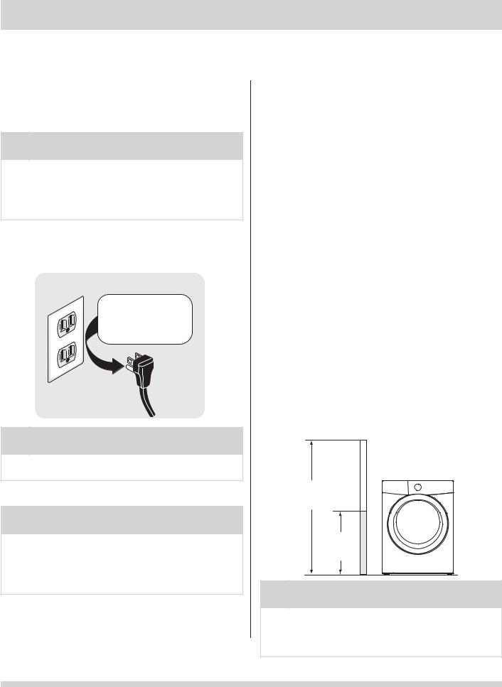
OUTLET RECEPTACLE - Properly grounded 3-prong receptacle to be located so the power supply cord is accessible when the washer is in an installed position.
Grounding type wall receptacle
Do not, under
any circumstances, cut, remove,
or bypass the grounding prong.
Power cord with
3-prong grounded plu
NOTE
GFI (Ground Fault Interrupter) receptacle is not required.
Ground requirements

 WARNING
ELECTRICAL SHOCK HAZARD
Improper connection of the equipment grounding conductor can result in a risk of electrical shock. Check with a licensed electrician if you are in doubt as to whether the appliance is properly grounded.
1The washer MUST be grounded. In the event of malfunction or breakdown, grounding will reduce the risk of electrical shock by a path of least resistance for electrical current.
2Since your washer is equipped with a power supply
cord having an equipment-grounding conductor and a grounding plug, the plug MUST be plugged into an appropriate, copper wired receptacle that is properly installed and grounded in accordance with all local codes and ordinances or in the absence
of local codes, with the National Electrical Codes, ANSI/NFPA 70 (latest edition). If in doubt, call a licensed electrician. DO NOT cut off or alter the grounding prong on the power supply cord. In situations where a two-slot receptacle is present, it is the owner’s responsibility to have a licensed
electrician replace it with a properly grounded three prong grounding type receptacle.
Water supply requirements
Hot and cold water faucets MUST be installed within 42 inches (107 cm) of your washer’s water inlet. The faucets MUST be 3/4 inch (1.9 cm) with threading for laundry hose connection. Water pressure MUST be between 30 and 120 psi. Pressure difference between hot and cold cannot be more than 10 psi. Your water department can advise you of your water pressure.
Drain system requirements
1Drain capable of eliminating 17 gals (64.3 L) per minute.
2A standpipe diameter of 1-1/4 in. (3.18 cm) minimum.
3The standpipe height above the floor should be: Minimum height: 24 in. (61 cm)
Maximum height: 96 in. (244 cm)
96”
(244cm)
max.
24”
(61cm)
min.
NOTE
Drain hose attached to the washer can reach a 74 in. (188 cm) high standpipe. For higher standpipe, use hose P/N 137098000, available from an authorized parts distributor.
4
INSTALLATION REQUIREMENTS
Clearance requirements

 IMPORTANT
DO NOT INSTALL YOUR WASHER:
1In an area exposed to dripping water or outside weather conditions. The ambient temperature should never be below 60° F (15.6° C) to maximize detergent effectiveness.
2In an area (garage or garage-type building) where gasoline or other flammables (including automobiles) are kept or stored.
3On carpet. Floor MUST be solid with a maximum slope of 1 inch (2.54 cm). To minimize vibration or movement, reinforcement of the floor may be necessary.
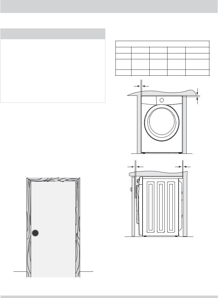
Installation in a Recess or Closet
If washer and dryer are installed in the same closet, door ventilation is required: A minimum of 120 square inches (774.2 cm²) of opening, equally divided at the top and bottom of the door, is required. Louvered openings should be located 3 inches (7.6 cm) from bottom and top of door. Air openings are required to be unobstructed when a door is installed. A louvered door with equivalent air openings for the full length of the door is acceptable.
 3”
3”  (7.6cm)
60 sq. in. (387.1cm²)
MINIMUM INSTALLATION CLEARANCES - Inches (cm)
|
SIDES |
REAR |
TOP |
FRONT |
|
Alcove |
0” (0 cm) |
0” (0 cm)* |
0” (0 cm) |
n/a |
|
Under- |
0” (0 cm) |
0” (0 cm)* |
0” (0 cm) |
n/a |
|
Counter |
|||||
|
|
|
|
||
Closet |
0” (0 cm) |
0” (0 cm)* |
0” (0 cm) |
1” (2.54 cm) |
|
|
0” |
|
|
|
|
|
(0cm) |
|
|
|
|
|
|
|
|
0” |
|
|
|
|
|
(0cm) |
|
1” |
|
|
0” |
|
|
(2.5cm) |
|
|
(0cm) |
|
60 sq. in. (387.1cm²)
 3”
3”  (7.6cm)
closet door
5

INSTALLED WASHER DIMENSIONS
51.4” (131cm) |
|
|
to clear open door |
30.3” (77cm)* |
27.0” |
|
to front of closed door |
|
|
(68.5cm) |
|
|
|
|
|
water supply |
|
|
connection on |
|
|
rear of unit1 |
|
|
drain hose on |
power cord on |
|
rear of unit2 |
|
|
rear of unit3 |
51.25” |
|
|
(130cm) |
|
|
36.0” |
|
|
(91.5cm) |
freestand washer on floor
floor line
washer mounted on optional pedestal
floor line
*To obtain these minimal depth dimensions, dryer must be vented straight back. Using a quick-turn 90° elbow (right or down on freestanding dryer) adds approximately 0.75 in. (2.0 cm) to installation depth. Upward venting of exhaust on pedestal-mounted or freestanding dryer adds approximately 4 in. (10.2 cm) to installation depth. Leftward venting on pedestal-mounted or freestanding dryer adds approximately 3.75 in. (9.5 cm) to installation depth. Downward venting of exhaust on pedestal-mounted dryer adds approximately 2.25 in. (5.7 cm) to installation depth.
1Hot and cold inlet hose length approximately 43 inches (109cm). 2Power supply cord length approximately 60 inches (152.5cm). 3Drain hose length approximately 52 inches (132cm).
51.4” (131cm) |
|
|
|
|
|
|
|
|
|
|
|
|
|
|
|
|
|
|
|
|
|
|
|
|
|
|
|
|
|
|
|
|
|
|
|
|
|
|
|
to clear open door |
|
|
|
30.3” (77cm)* |
|
|
|
|
|
|
|
|
|
27.0” |
|
||||
|
|
|
|
|
|
|
|
|
|
|
|
|
|||||||
|
|
|
|
to front of closed door |
|
|
|
|
|
|
|
|
(68.5cm) |
||||||
|
|
|
|
|
|
|
|
|
|
|
|
|
|
|
|
|
|
||
|
|
|
|
|
|
|
|
|
|
|
|
|
|
|
|
|
|
|
|
|
|
|
|
|
|
|
|
|
|
|
|
|
|
|
|
|
|
|
|
|
|
|
|
|
|
|
|
|
|
|
|
|
|
|
|
|
|
|
|
|
|
|
|
|
|
|
|
|
|
|
|
|
|
|
|
|
|
|
|
|
|
|
|
|
|
|
|
|
|
|
|
|
|
|
|
|
|
|
|
|
|
electrical |
71.5” |
|
supply on |
(182cm) |
|
rear of unit |
|
water supply |
|
|
connection on |
|
|
rear of unit1 |
|
|
|
centerline |
|
gas supply |
height for |
|
rear vent |
|
|
pipe on rear |
|
|
|
|
|
of gas unit |
|
power cord on 37” rear of unit2
(94cm)
drain hose on rear of unit3
39”
(99cm)
*To obtain these minimal depth dimensions, dryer must be vented straight back. Using a quick-turn 90° elbow (right) adds approximately 0.75 in. (2 cm) to installation depth. Upward venting of exhaust on stacked dryer adds approximately 4 in. (10.2 cm) to installation depth. Downward venting of exhaust on stacked dryer adds approximately 2.25 in. (6.5 cm) to installation depth. Leftward venting of exhaust on stacked dryer adds approximately 3.75 in. (9.5 cm) to installation depth.
1Hot and cold inlet hose length approximately 43 inches (109cm) 2Power supply cord length approximately 60 inches (152.5cm).
3Drain hose length approximately 52 inches (132cm).
6

UNPACKING WASHER
Removing foam packaging

 WARNING
SUFFOCATION HAZARD
Destroy the carton and plastic bags after the washer is unpacked. Children might use them for play. Cartons covered with rugs, bedspreads, or plastic sheets can become airtight chambers causing suffocation. Place all materials in a garbage container or make materials inaccessible to children.
1 Temporarily remove door tape.
2 Open washer door and remove everything from the drum.
3 Close door and reapply door tape.
4Using a rug, blanket or piece of cardboard to protect the floor, carefully lay the washer on it’s back.

 CAUTION
EXCESSIVE WEIGHT HAZARD
To avoid back or other injury, have more than one person move or lift the washer.
5Remove styrofoam base and shipping plug and set them aside.
6 Carefully return the washer to an upright position.
7 Carefully move the washer to within 4 feet (1 m) of its final location.

 IMPORTANT
Save styrofoam base and shipping plug for use to help prevent washer damage during any future moves.
7
UNPACKING WASHER
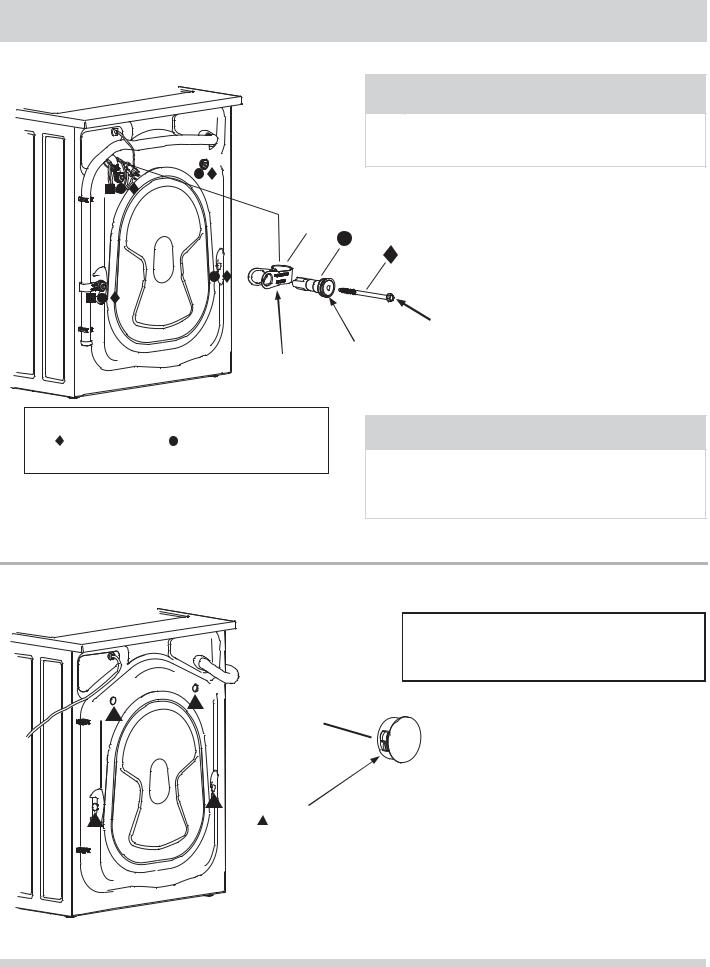
Removing shipping hardware
NOTE
Rubber expansion material on spacers may need time to relax before they can be easily pulled through shipping hole.
 x 2
x 2
x 4
x 4
 2 P CLAMPS
Remove all of the following:
|
4 BOLTS |
4 SPACERS |
|
2 P CLAMPS |
|
|
|
 4 BOLTS
 4 SPACERS

 IMPORTANT
Save all shipping bolts and spacers for future use. If the washer is to be transported at a later date, the shipping hardware must be reinstalled to help prevent shipping damage.
Installing hole plugs
Locate 4 hole plugs in the small bag supplied with washer instruction guides. Insert them in the holes in washer back panel.
 x 4
x 4
4 HOLE PLUGS (IN BAG)
8
 Loading...