

Frigidaire FAS12P2ABJW, FAC09P2ABJW, FAC12P2ABJW, FAS18C2ABJW, FAS24P2ABJW Instruction Manual
...
FRIGIDAIR
INSTRUCTIONS MANUAL
SPL|T TYPE ROOM AIR CONDITIONER
ATTENTION
Please read this manual completely
before operating your room air conditioner.
Welcome to the world of
simple handling and no worries.
Thank you for choosing Frigidaire. This manual contains all of the information
required to guarantee your safety and the appropriate use of your air
conditioner.
Please read all of the instructions before using the air conditioner and keep this
manual for future reference.
We know you will enjoy your new air conditioner and thank you for choosing
our product. We hope you will consider us for future purchase.
Environmental advices
The packaging material used is
recyclable; we recommend that you
separate plastic, paper and cardboard
and give them to recyoling companies.
According to WEEE (Waste of Electrical
and Electronic Equipment) guidelines,
waste from electrical and electronic
devices should be collected separately, If
you need to dispose of this appliance in
the future, do NOT throw it away with the
rest of your domestic garbage. Instead,
please take the appliance to the nearest
WEEE collection point, where available.
Contents
01, Welcome ........................................................................................... 01
02. Environmental advices .......................................................................... 01
03. Contents ................................................................................................... 02
04. Safety precautions ..................................................................... 04
05. installation:
5.1 Choosing the installation site ....................................................... 08
5.2 Parts list ......................................................................................... 10
5.3 Indoor unit installation ................................................... 12
5.4 Outdoor unit installation .............................................................. 17
5,5 Refrigerant piping connection ........................................................ 19
5.6 Electrical work ..................................................................... 21
5,7 Purga de aire ............................................................................. 26
5.8 Electrical safety, ................................................................... 29
5.7 Gas leak check ............................................................................... 29
5.8 Test running ............................................................................. 30
06, Operation:
6.1 Preparing the device for operation .............................. 31
6.2 Product description ........................................................... 32
6.3 Remote control ................................................................... 34
- Remote control operation
- Remote control specifications
- Remote control battery
- When should the batteries be replaced
- To replace batteries
- Remote control instructions
6.4 Remote control description .................................................... 36
- On/Off
- Temp. increase
- Temp, decrease
- Swing
Clock
- Turbo
- Mode
- Fan speed
- Sleep
- Timer
- Cancel
- LED (screen)
6.5 LCD display indicators .................................................................. 38
6.6 How the air conditioner works ................................... 39
- Automatic operation
-Cool/heatandfanonlyoperation
- Dryoperation
-Airflowdirectionadjustment
-Sleepmode
-Timeroperation
-Optimal operation
6,7 How to use the indoor unit...................................................... 43
- Adjusting air flow direction
- Adjusting the vertical air flow direction (up/down)
- To set the horizontal air flow direction (left/right)
- To automatically swing the air flow direction (up/down)
6.8 Manual operation ........................................................................ 45
07. Maintenance .................................................................................... 46
08. Operation tips .......................................................................................... 48
09. Solution for problems .............................................................................. 50
I0. Technical specifications ..................................................................... 51
Attention
The air conditioner that you have bought may be slightly different from the
one illustrated in this manual. Please refer to the information related to the
model you have.
This air conditioner is for domestic use only. It is not reccomended for
commercial or industrial use.
The air conditioner you have may carry a different plug than the one
illustrated in this manual, The plug that comes with the product fo]Iows the
electrical specification of the country where it is sold.
Safety precautions
To prevent iniury to the user or other people and property damage, the
following instructions must be followed.
Incorrect operation due to ignon_ng of instructions may cause harm or damage.
The seriousness is classified by the following indications.
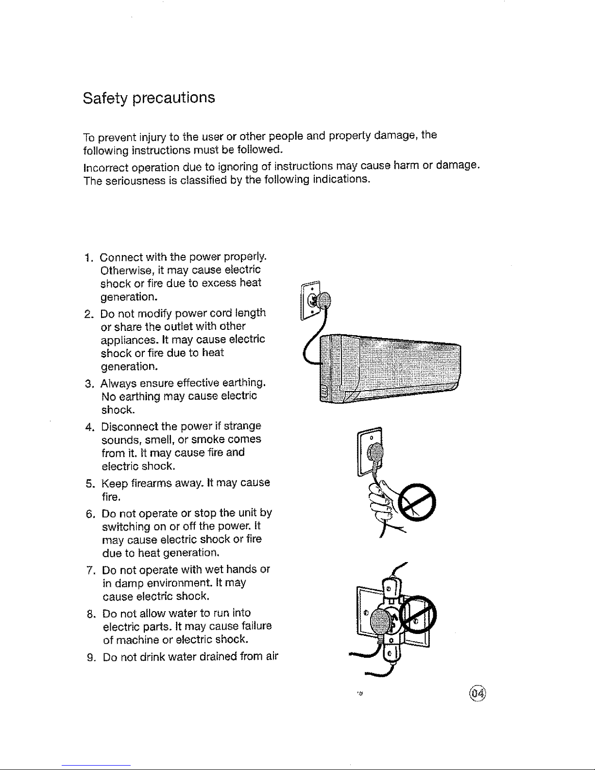
1. Connect with the power properly.
Otherwise, it may cause electric
shock or fire due to excess heat
generation.
2. Do not modify power cord length
or share the outlet with other
appliances. It may cause electric
shock or fire due to heat
generation.
3, Always ensure effective earthing,
No earthing may cause electric
shock.
4. Disconnect the power if strange
sounds, smell, or smoke comes
from it, tt may cause fire and
electric shock,
5. Keep firearms away. It may cause
fire.
6, Do not operate or stop the unit by
switching on or off the power, tt
may cause electric shock or fire
due to heat generation,
7, Do not operate with wet hands or
in damp environment. It may
cause electric shock,
8. Do not allow water to run into
electric parts. It may cause failure
of machine or electric shock.
9. Do not drink water drained from air
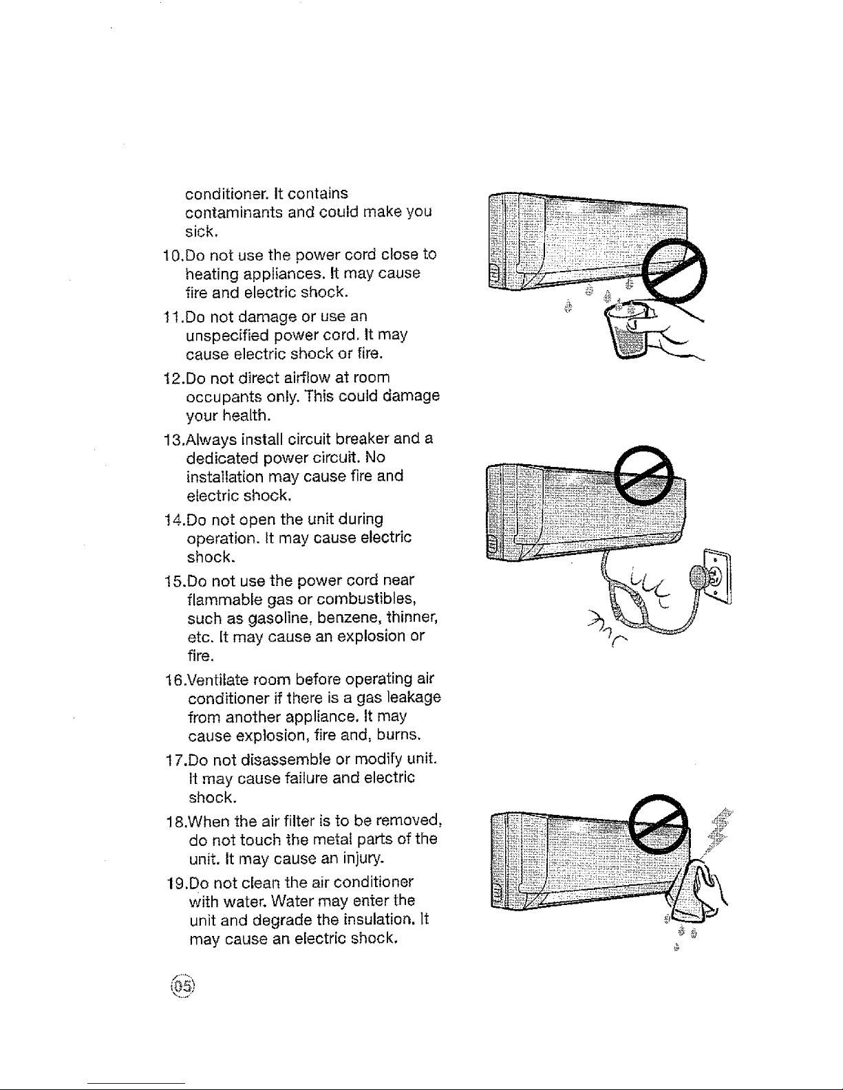
conditioner.Itcontains
contaminantsandcouldmakeyou
sick,
10.Donotusethepowercordcloseto
heatingappliances.Itmaycause
fireandelectricshock.
11.Do not damage or use an
unspecified power cord. It may
cause electric shock or fire.
12.Do not direct airflow at room
occupants only. This could damage
your health.
1&Always install circuit breaker and a
dedicated power circuit. No
installation may cause fire and
electric shock,
14.Do not open the unit during
operation. It may cause electric
shock.
15.Do not use the power cord near
flammable gas or combustibles,
such as gasoline, benzene, thinner,
etc. It may cause an explosion or
fire.
I &Ventilate room before operating air
conditioner if there is a gas leakage
from another appliance, It may
cause explosion, fire and, burns.
17.Do not disassemble or modify unit.
It may cause failure and electric
shock.
18.When the air filter is to be removed,
do not touch the metat parts of the
unit, It may cause an injury.
19,Do not clean the air conditioner
with water. Water may enter the
unit and degrade the insulation. It
may cause an electric shock,
\,...J
20.Ventilate the room well when used
together with a stove, etc. An
oxygen shortage may occur.
21.When the unit is to be cleaned,
switch off, and turn off the circuit
breaker. Do not clean unit when
power is on as it may cause fire
and electric shock, it may cause
an iniury.
22.Do not put a children, pet or house
plant where it will be exposed to
direct air flow. This could injure the
pet or plant.
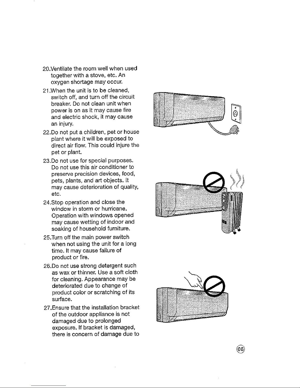
23.Do not use for special purposes.
Do not use this air conditioner to
preserve precision devices, food,
pets, plants, and art objects. It
may cause deterioration of quality,
etc.
24.Stop operation and close the
window in storm or hurricane.
Operation with windows opened
may cause wetting of indoor and
soaking of household furniture.
25.Turn off the main power switch
when not using the unit for a long
time. It may cause failure of
product or fire.
26.Do not use strong detergent such
as wax or thinner. Use a soft cloth
for cleaning. Appearance may be
deteriorated due to change of
product color or scratching of its
surface.
27.Ensure that the installation bracket
of the outdoor appliance is not
damaged due to prolonged
exposure. If bracket is damaged,
there is concern of damage due to
®
falling of unit.
28.Always insert the filters securely.
Clean filter once every two weeks,
Operation without filters may cause
failure.
29.Do not place heavy object on the
power cord and take care so that
the cord is not compressed. There
is danger of fire or electric shock.
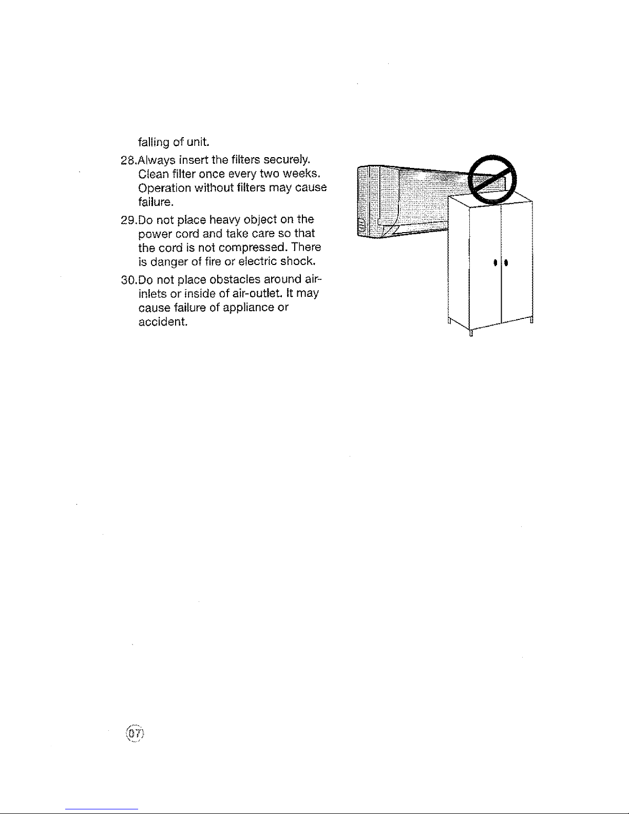
30.Do not place obstacles around air-
inlets or inside of air-outlet. It may
cause failure of appliance or
accident.
Choosing the Installation Site
Precautions for Installation
installation at the following sites may cause problems. If you must inevitably
install the unit at one of these sites, please consult your local distributor
beforehand:
1. Site with machine oil.
2. Sites with a high concentration of salinity, such as coastal areas.
3. Sites with sulfuric gas, such as hot water springs.
4. Sites with high frequency equipment, such as wireless equipment, welding
machines and medical installations.
5. Sites with flammable gases or volatile material.
6. Sites with special environmental conditions.
7. Laundry rooms.
Indoor Unit
1. The unit must be installed at a site
that does not obstruct the flow of
air.
2. The site must support the weight
of the indoor unit.
3. The site must be easily accessible
for maintenance and replacement
of the air filter.
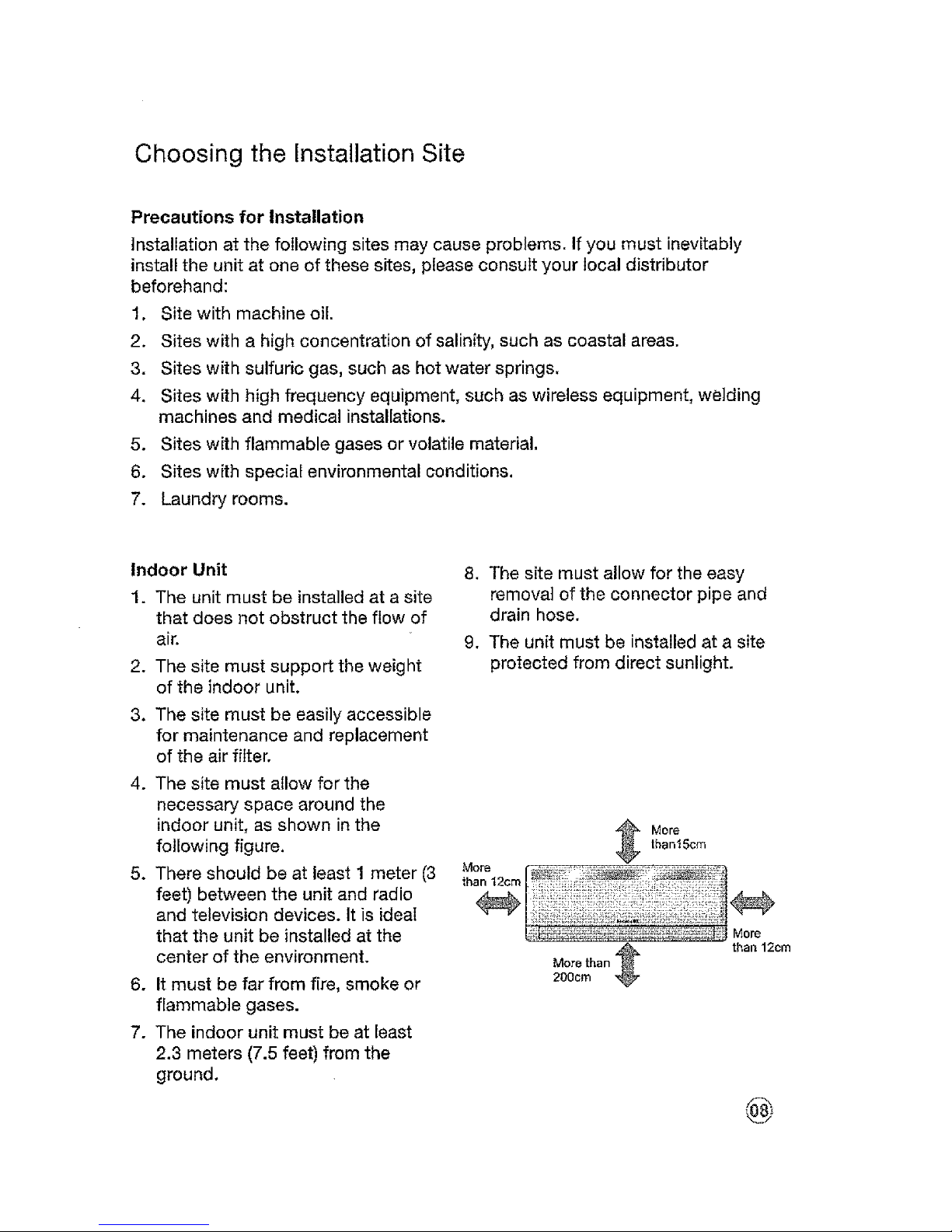
4. The site must allow for the
necessary space around the
indoor unit, as shown in the
following figure.
5. There should be at least 1 meter (3
feet) between the unit and radio
and television devices. It is idea[
that the unit be installed at the
center of the environment.
6. It must be far from fire, smoke or
flammable gases.
7. The indoor unit must be at least
2.3 meters (7.5 feet) from the
ground.
8. The site must allow for the easy
removal of the connector pipe and
drain hose.
9. The unit must be installed at a site
protected from direct sunlight.
More
thantScm
More than
200cm
than 12cm
@
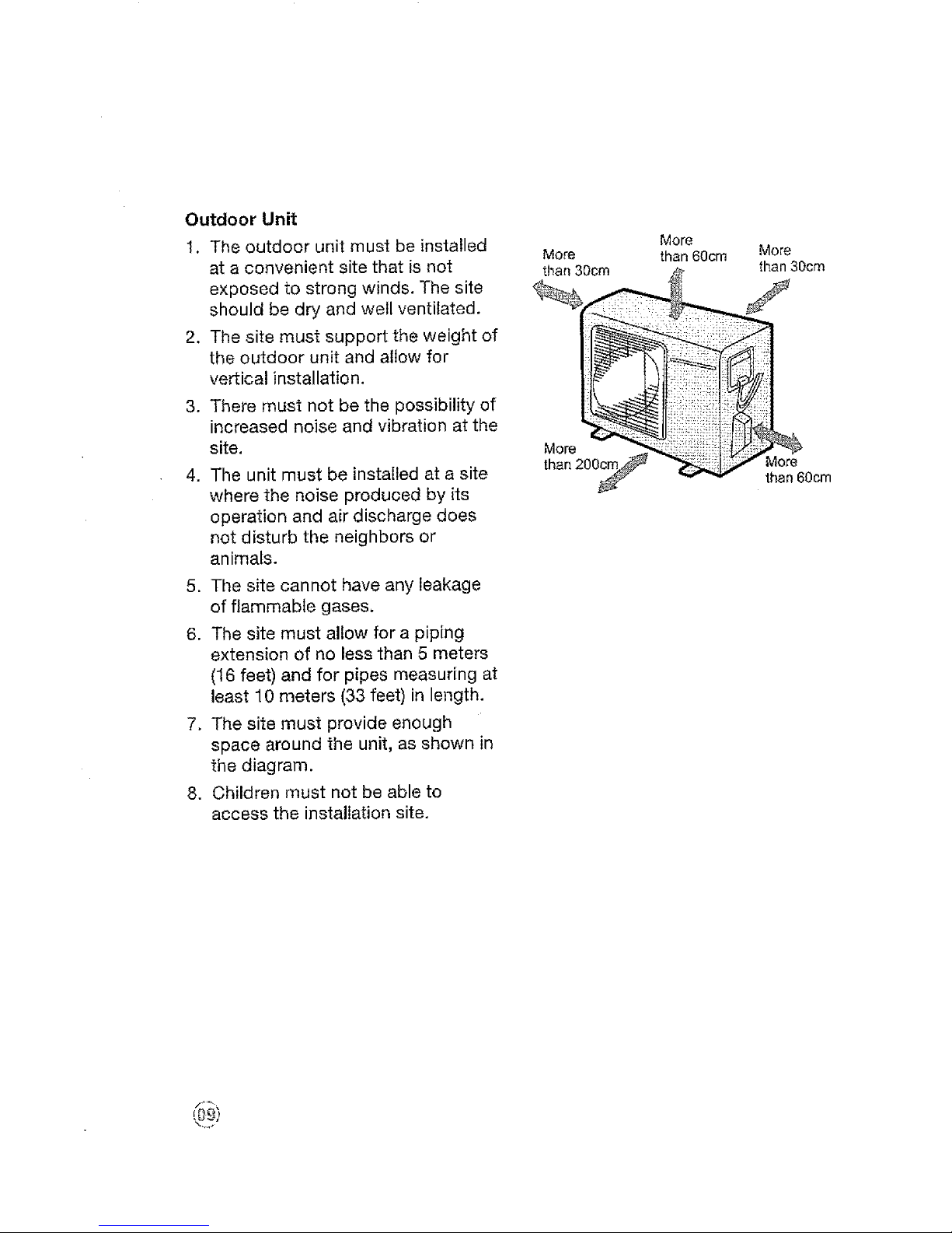
Outdoor Unit
1, The outdoor unit must be installed
at a convenient site that is not
exposed to strong winds. The site
should be dry and well ventilated.
2. The site must support the weight of
the outdoor unit and allow for
vertical installation.
3. There must not be the possibility of
increased noise and vibration at the
site.
4. The unit must be installed at a site
where the noise produced by its
operation and air discharge does
not disturb the neighbors or
animals.
5. The site cannot have any leakage
of flammable gases.
6. The site must allow for a piping
extension of no less than 5 meters
(16 feet) and for pipes measuring at
least 10 meters (33 feet) in length.
7, The site must provide enough
space around the unit, as shown in
the diagram.
8. Children must not be able to
access the installation site.
More
than 30cm
Mor_
than 200 S
More
than60cm More
than30cm
f
t??il !i
More
then 60cm

Parts list
Endoor unit
@ @
Outdoor unit
L!oj
More than
Air filte
More than
A
@
More than 60cm
More
than 60cm
B C
More than 200cm Outdoor
Unit
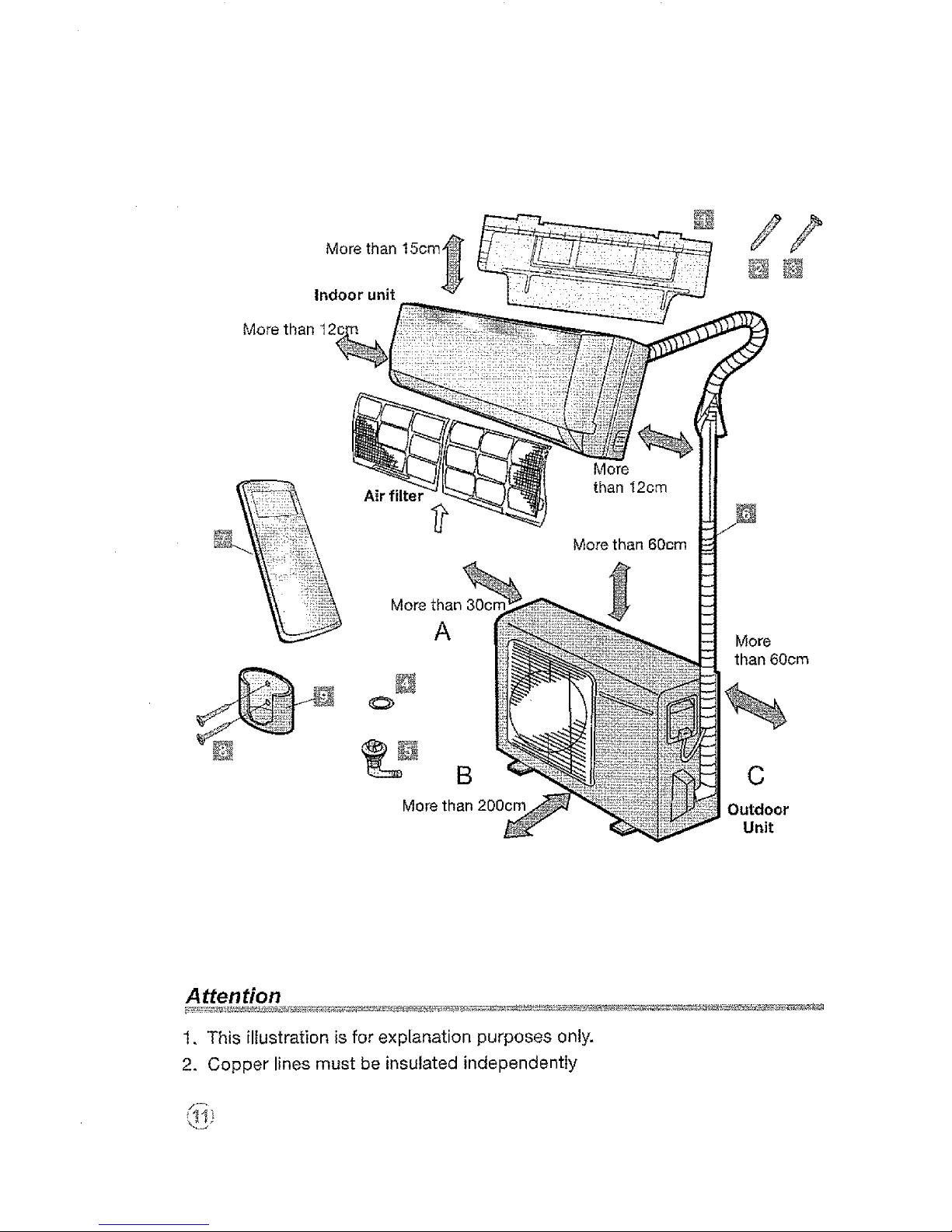
Attention
1. This illustration is for explanation purposes only.
2. Copper lines must be insulated independently
\_..J
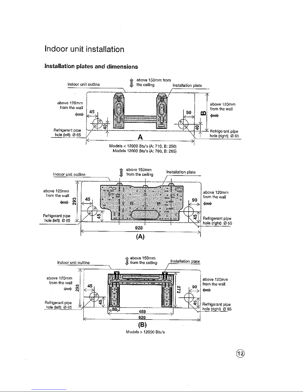
Indoor unit installation
Installation plates and dimensions
indoor unfl outline
above 150mm from
the ceiling Installation plate
above 120ram
from the wal!
Refri.gerae.t pipe
bole (left) O 65
i 45
A
Models < 12000 Btu's (A: 710, B: 250)
Models t2D00 Btu's (A: 790, 8: 265)
above 120ram
from the wall
pipe
hole (right) _ 65
Indoor unit outline
above 120ram
from the walt
Refrigerant p]pe
hole (left) 0 65
above 150ram
920
(A)
above 120ram
from the waU
4_F
Refrigerant pipe
hole (right) 0 65
l_doo_ unit out{i_
above 120mm
from the wail
Refrigerant p_pe
hole
_ above 150ram
from the ceiling
Installation plate
i above 120ram
i from the wall
£efrigeraht pipe
8 65
(B)
Models > 12000 Btu's
above120ram
fromwall
Refrigerant pipe
hole (left) O g5
above 150ram from
ceiling
1080
432 432
Indoor unit outline
Models 24000 Btu's
Models 30000 Btu's
above 120ram
from wall
above 120ram
from wall
above "E5Omm from ceiling
1250
815 . 257
Refrigerant pipe
hoIe (right) e 95
j--
above120mm
from wall
58
Indoor unit outline
Models 30000 Btu's
Models 36000 Btu's
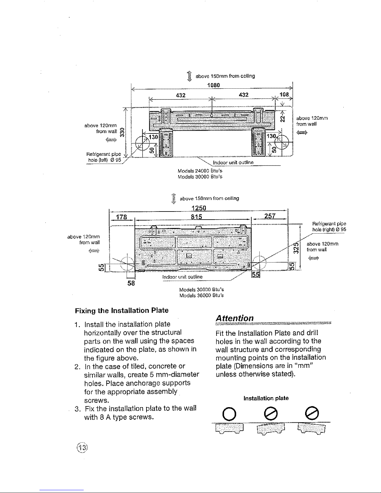
Fixing the Installation Plate
1. Install the installation plate
horizontally over the structural
parts on the wall using the spaces
indicated on the plate, as shown in
the figure above.
2. In the case of tiled, concrete or
similar walls, create 5 mm-diameter
holes. Place anchorage supports
for the appropriate assembly
screws.
3. Fix the installation plate to the wall
with 8 A type screws.
Attention
Fit the installation Plate and drill
holes in the wall according to the
wall structure and corresponding
mounting points on the installation
plate (Dimensions are in "mm"
unless otherwise stated).
Installation plate
0 @ @
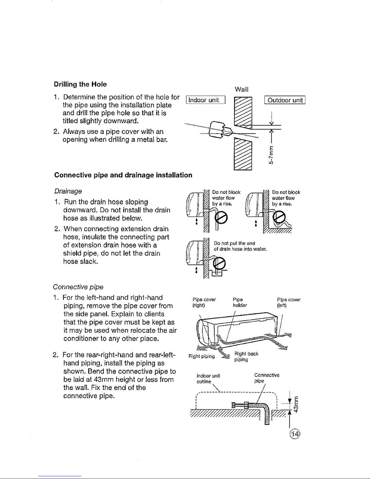
Drilling the Hole
Wall
1. Determine the position of the hole for [Indoor unit i _
the pipe using the installation plate
and drill the pipe hole so that it is
titled slightly downward .............. iii"_._... _.
2, Always use a pipe cover with an 1"
opening when drilling a metal bar. ....
E
E
Connective pipe and drainage installation
[ Outdoor unit I
Drainage
1, Run the drain hose sloping
downward. Do not install the drain
hose as illustrated below,
2. When connecting extension drain
hose, insulate the connecting part
of extension drain hose with a
shield pipe, do not let the drain
hose slack.
Do not put the end
of drain hose into water.
Connective pipe
1. For the left-hand and right-hand
piping, remove the pipe cover from
the side panel. Explain to clients
that the pipe cover must be kept as
it may be used when relocate the air
conditioner to any other place.
P_pe cover Pipe Pipe cover
(right) holder (left)
2. For the rear-right-hand and rear-left-
hand piping, install the piping as
shown. Bend the connective pipe to
be laid at 43mm height or less from
the wall. Fix the end of the
connective pipe.
Right piping Right back
piping
Indoor unit Connective
outline pipe
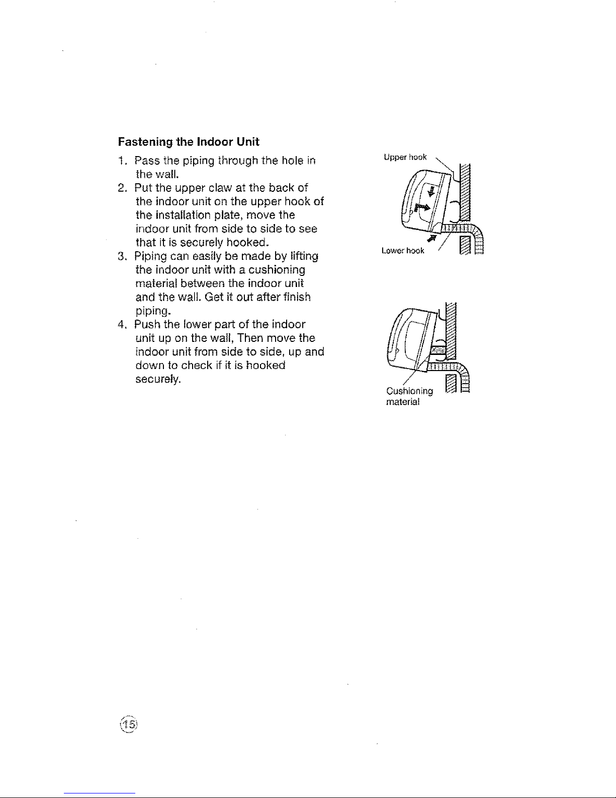
Fastening the Indoor Unit
1. Pass the piping through the hole in
the wall.
2. Put the upper claw at the back of
the indoor unit on the upper hook of
the insta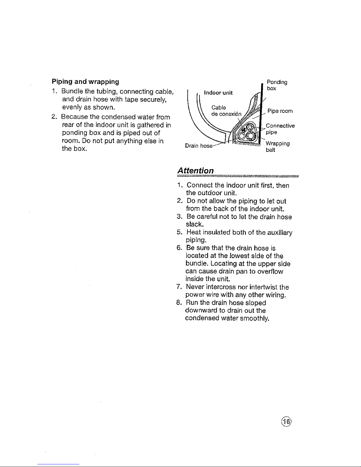
Piping and wrapping
1. Bundle the tubing, connecting cable,
and drain hose with tape securely,
evenly as shown.
2. Because the condensed water from
rear of the indoor unit is gathered in
ponding box and is piped out of
room. Do not put anything else in
the box.
l . Indoor unit
Ponding
box
Pipe room
Connective
_pipe
_Wrapping
belt
Attention
1. Connect the indoor unit first, then
the outdoor unit.
2. Do not allow the piping to let out
from the back of the indoor unit.
3. Be careful not to let the drain hose
slack.
5. Heat insulated both of the auxiliary
piping.
6. Be sure that the drain hose is
located at the lowest side of the
bundle. Locating at the upper side
can cause drain pan to overflow
inside the unit.
7. Never intercross nor intertwist the
power wire with any other wiring.
8. Run the drain hose sloped
downward to drain out the
condensed water smoothly.
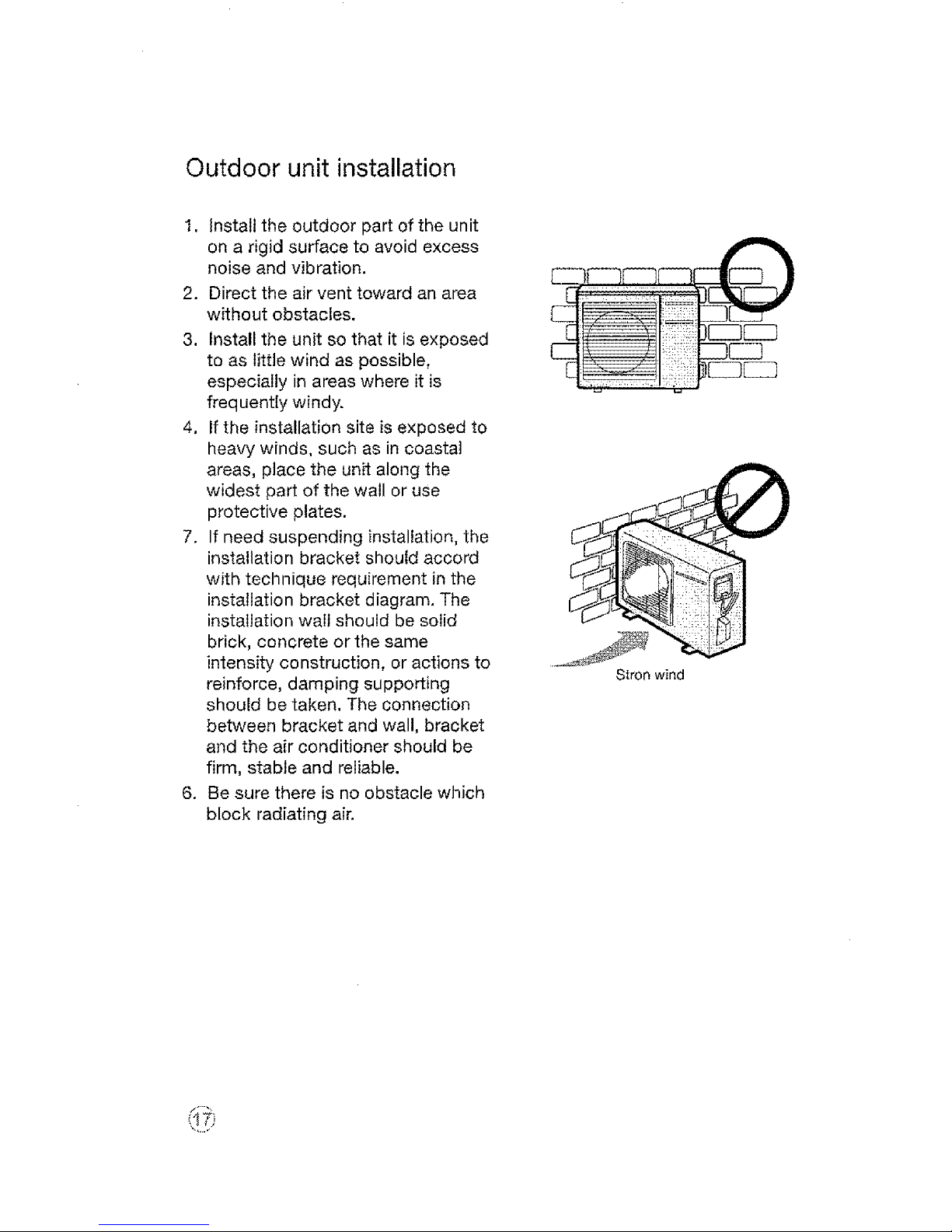
Outdoor unit installation
1. Install the outdoor part of the unit
on a rigid surface to avoid excess
noise and vibration.
2. Direct the air vent toward an area
without obstacles,
3. Install the unit so that it is exposed
to as little wind as possible,
especially in areas where it is
frequentiy windy.
4, If the installation site is exposed to
heavy winds, such as in coastal
areas, place the unit along the
widest part of the wall or use
protective plates.
7. If need suspending installation, the
installation bracket should accord
with technique requirement in the
installation bracket diagram. The
installation wait should be solid
brick, concrete or the same
intensity construction, or actions to
reinforce, damping supporting
should be taken. The connection
between bracket and wall, bracket
and the air conditioner should be
firm, stable and reliable.
6. Be sure there is no obstacle which
block radiating air.
Stron wind
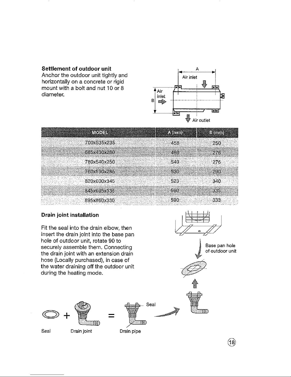
Settlement of outdoor unit
Anchor the outdoor unit tightly and
horizontally on a concrete or rigid
mount with a bolt and nut I0 or 8
diameter,
A,r,n,et0
Air 'i'
i%
Drain joint installation
Fit the seal into the drain elbow, then
insert the drain joint into the base pan
hole of outdoor unit, rotate 90 to
securely assemble them, Connecting
the drain joint with an extension drain
hose (Locally purchased), in case of
the water draining off the outdoor unit
during the heating mode.
/*
Seal Drain joint Drain pipe
Base pan hole
of outdoor unit
@
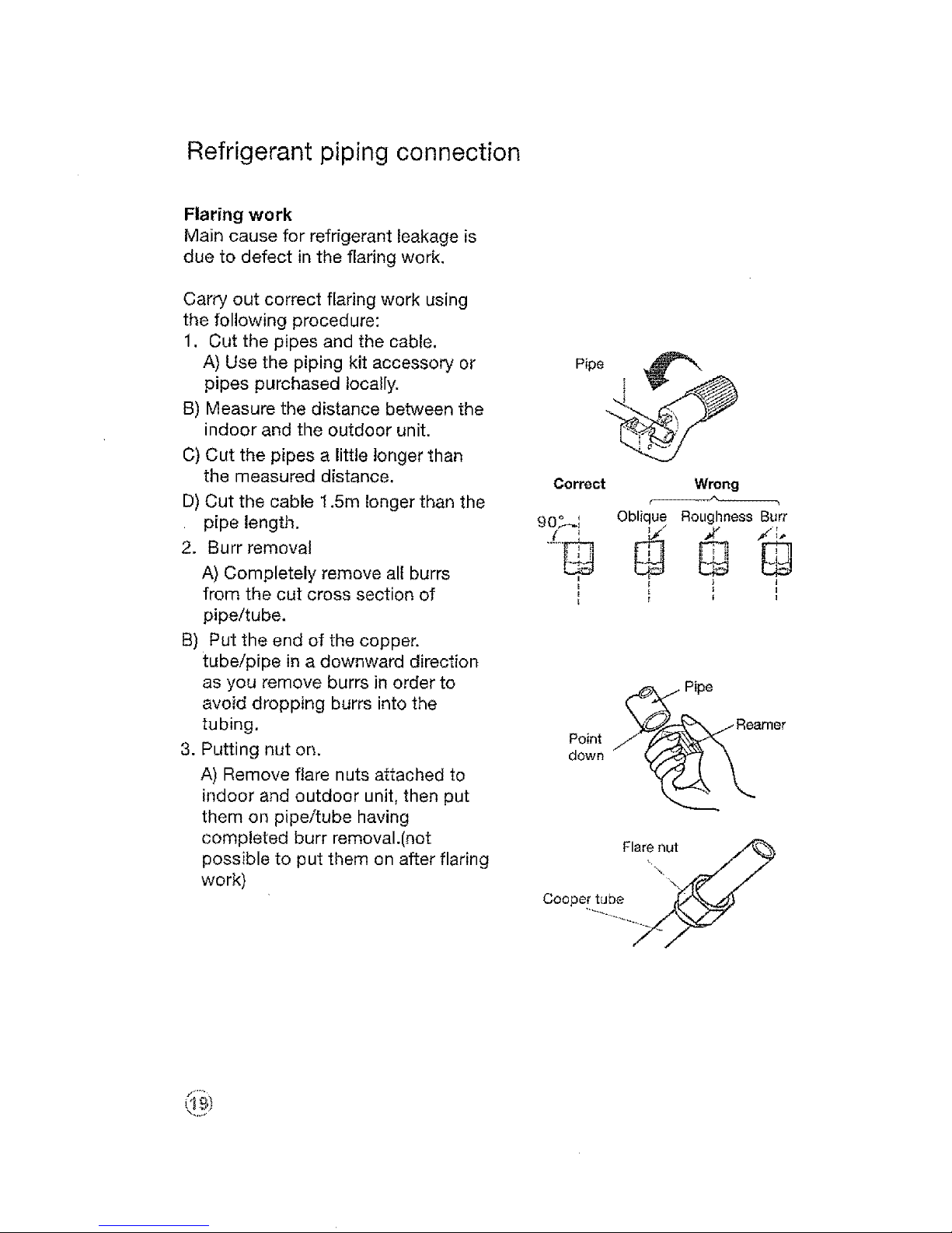
Refrigerant piping connection
Flaring work
Main cause for refrigerant leakage is
due to defect in the flaring work,
Carry out correct flaring work using
the following procedure:
1. Cut the pipes and the cable,
A) Use the piping kit accessory or
pipes purchased locally.
B) Measure the distance between the
indoor and the outdoor unit.
C) Cut the pipes a little longer than
the measured distance.
D) Cut the cable 1.5m longer than the
pipe length.
2, Burr removal
A) Completely remove all burrs
from the cut cross section of
pipe/tube,
B) Put the end of the copper.
tube/pipe in a downward direction
as you remove burrs in order to
avoid dropping burrs into the
tubing,
3. Putting nut on,
A) Remove flare nuts attached to
indoor and outdoor unit, then put
them on pipe/tube having
completed burr removal.(not
possible to put them on after flaring
work)
Correct Wrong
90,%_'_ Oblique Roughness Burr
i
_,,._ Pipe
down
Flare nut
\.
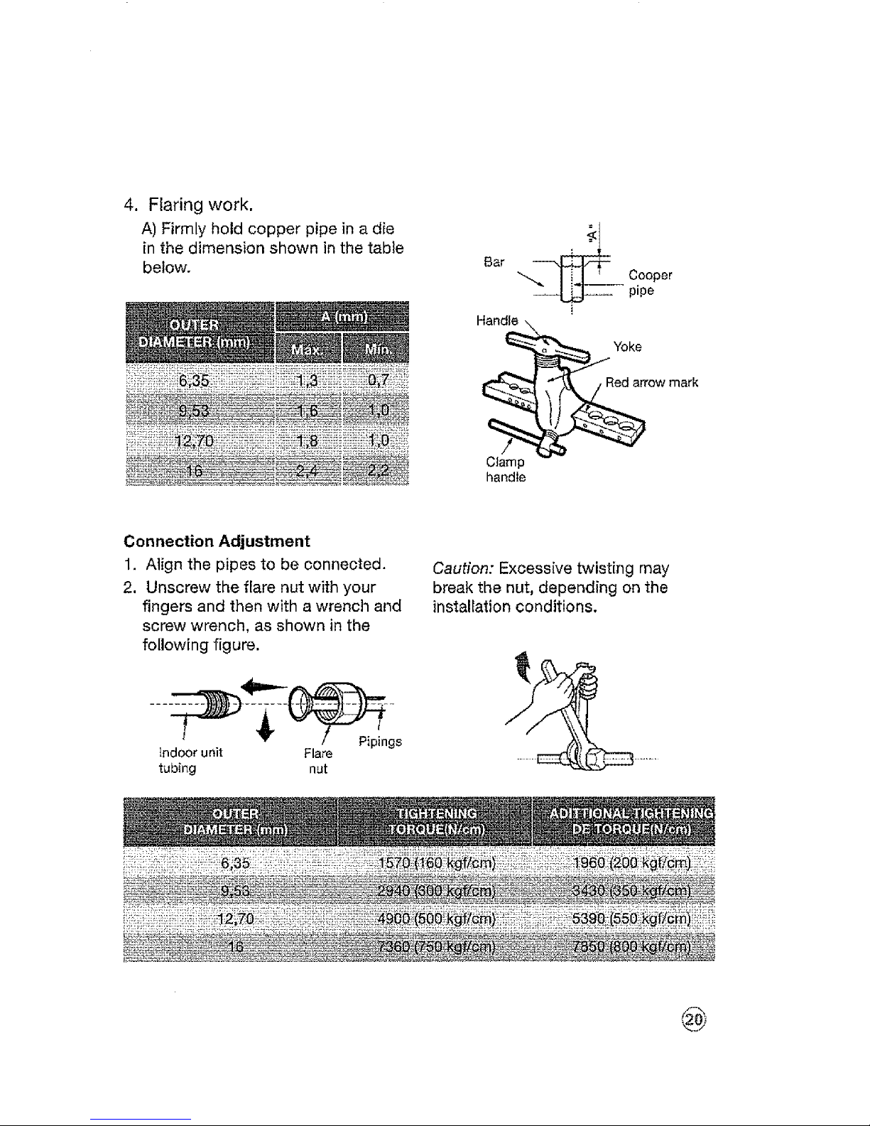
4.
Flaring work.
A) Firmly hold copper pipe in a die
in the dimension shown in the table
below.
Bar
Cooper
-- pipe
Clamp
handle
Connection Adjustment
1. Align the pipes to be connected.
2. Unscrew the flare nut with your
fingers and then with awrench and
screw wrench, as shown in the
following figure.
indoor unit Flare
tubing nut
Caution: Excessive twisting may
break the nut, depending on the
installation conditions.
@
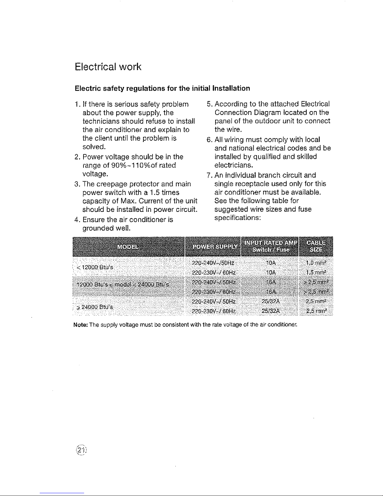
Electrical work
Electric safety regulations for the initial Installation
1. if there is serious safety problem
about the power supply, the
technicians should refuse to install
the air conditioner and explain to
the client until the problem is
solved.
2. Power voltage should be in the
range of 90%-110%of rated
voltage.
3. The creepage protector and main
power switch with a 1.5 times
capacity of Max. Current of the unit
should be installed in power circuit.
4. Ensure the air conditioner is
grounded well,
5. According to the attached Electrical
Connection Diagram located on the
panel of the outdoor unit to connect
the wire.
6. All wiring must comply with local
and national electrical codes and be
installed by qualified and skilled
electricians.
7. An individual branch circuit and
single receptacle used only for this
air conditioner must be available.
See the following table for
suggested wire sizes and fuse
specifications:
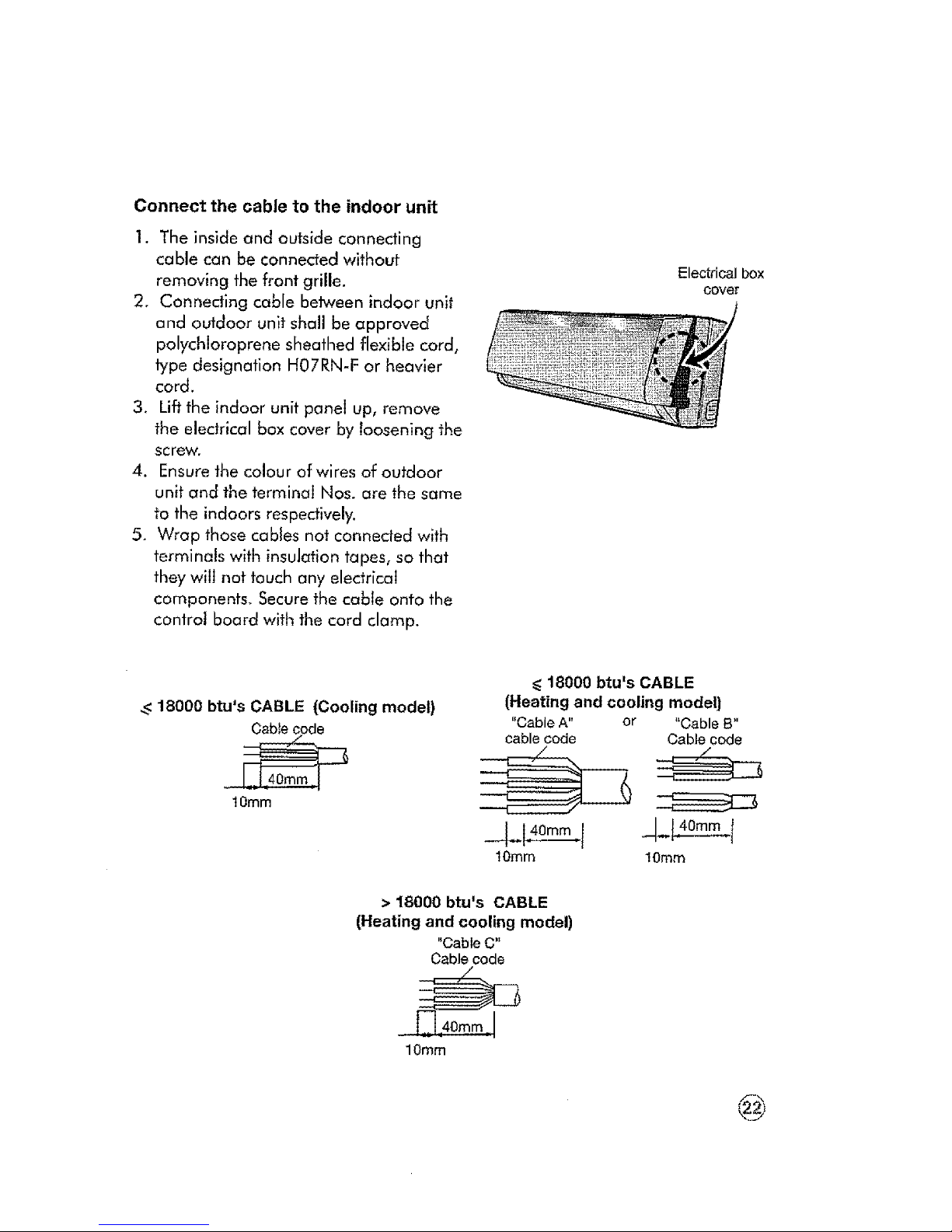
Connect the cable to the indoor unit
1. The inside and ou|side connecting
cable can be connected without
removing the front grille.
2. Conneding cable between indoor unit
and outdoor unit shall be approved
polychloroprene sheathed flexible cord,
type designation H07RN-F or heavier
cord.
3. Liftthe indoor unit panel up, remove
the electrical box cover by loosening the
screw.
4. Ensure the colour of wires of outdoor
unit and the terminal Nos. are the same
fo the indoors respectively.
5. Wrap those cables not conneded with
terminals with insulation tapes, so that
they will not touch any electrical
companents. Securethe cable onto the
control board with the card clamp.
Electrical box
cover
_<18000 btu's CABLE (Cooling model)
Cable code
1Omm
_<18000 btu's CABLE
(Heating and cooling model)
"Cable A" or "Cable B"
cable code Cable code
10mrn 10ram
> 18000 btu's CABLE
(Heating and cooling model)
"Cable C"
Cable code
10ram
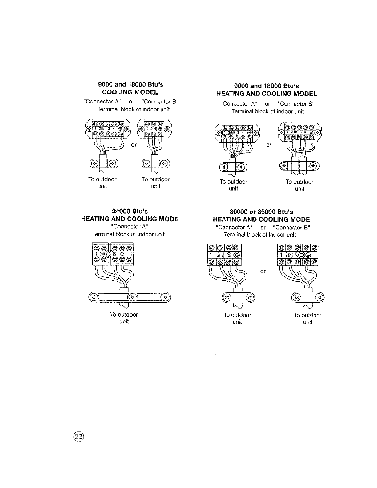
9000 and 18000 Btums
COOLING MODEL
"Connector A'_ or "Connector B"
Terminat block of indoor unit
To outdoor To outdoor
unit unit
9000 and 18000 Btu's
HEATING AND COOLING MODEL
"Connector A" or "Connector B"
Terminal block of indoorunit
To outdoor To outdoor
unit unit
24000 Btu's 30000 or 36000 Btu's
HEATING AND COOLING MODE HEATING AND COOLING MODE
"Connector A" "Connector A '_ or "Connector B"
Terminal block ofindoor unit Terminal block of indoor unit
or I
To outdoor To outdoor To outdoor
unit unit unit
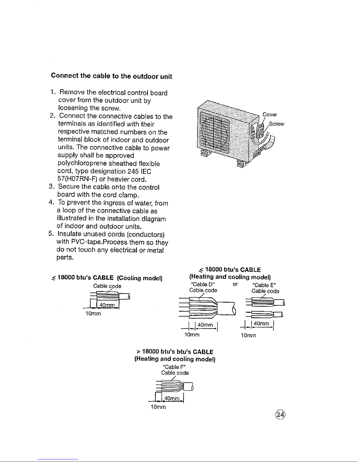
Connect the cable to the outdoor unit
1. Remove the electrical control board
cover from the outdoor unit by
loosening the screw.
2. Connect the connective cables to the
terminals as identified with their
respective matched numbers on the
terminal block of indoor and outdoor
units. The connective cable to power
supply shall be approved
polychloroprene sheathed flexible
cord, type designation 245 IEC
57(H07RN-F) or heavier cord.
3. Secure the cable onto the control
board with the cord clamp,
4. To prevent the ingress of water, from
a loop of the connective cable as
illustrated in the installation diagram
of indoor and outdoor units.
5. Insulate unused cords (conductors)
with PVC-tape.Process them so they
do not touch any electrical or metal
parts.
_<18000 btu's CABLE (Cooling model)
Cablecode
!0turn
Cover
;crew
_<18000 btu's CABLE
(Heating and cooling model)
+'CableD" or "Cable E"
Cable code Cable code
10ram 10ram
> 18000 btu's btu's CABLE
(Heating and cooling model)
"Cable F"
Cable code
10turn
@
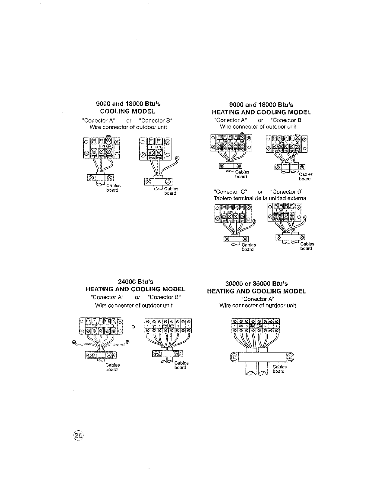
9000 and 18000 Btu's
COOLING MODEL
"Conector A" or "Conector B"
Wire connector of outdoor unit
c_ ©
board
board
9000 and 18000 Btu's
HEATING AND COOLING MODEL
"Conector A" or "Conector B"
Wire connector of outdoor unit
board board
"Conector C" or "Conector D"
Tablero terminal de Ia unidad externa
N
board board
24000 Btu's
HEATING AND COOLING MODEL
"Conector A" or "Conector B"
Wire connector of outdoor unit
W__I ,o,o_°,o,o,o,°,,,
Cables board
board
30000 or 36000 Btu's
HEATING AND COOLING MODEL
"(]onector A"
Wire connector of outdoor unit
UW
board
Caution
After the confirmation of the above conditions, prepare the wiring as follows:
1. Never fail to have an individual power circuit specifically for the air
conditioner. As for the method of wiring, be guided by the circuit diagram
posted on the inside of control cover,
2. The screw which fasten the wiring in the casing of electrical fittings are
liable to come loose from vibrations to which the unit is subjected during
the course of transportation, Check them and make sure that they are all
tightly fastened. (if they are loose, it could cause burn-out of the wires.)
3. Specification of power source.
4. Confirm that electricat capacity is sufficient.
5. See to that the starting voltage is maintained at more than 90 percent of the
rated voltage marked on the name plate.
6. Confirm that the cable thickness is as specified in the power source
specification.
7. Always install an earth leakage circuit breaker in a wet or moist area.
8. The following would be caused by voltage drop, Vibration of a magnetic
switch, which will damage the contact point, fuse breaking, disturbance of
the normal function of the overload.
9. The means for disconnection from a power supply shall be incorporated in
the fixed wiring and have an air gap contact separation of at least 3mm in
each active (phase) conductors.
Air purging
Air and moisture in the refrigerant system have undesirable effects as
indicated below:
1, Pressure in the system rises.
2. Operating current rises.
3. Cooling or heating efficiency
drops.
4. Moisture in the refrigerant circuit
may freeze and block capillary
tubing.
5. Water may lead to corrosion of
parts in the refrigeration system.
6, Therefore, the indoor unit and
tubing between the indoor and
outdoor unit must be leak tested
and evacuated to remove any
noncondensables and moisture
from the system.
Air purging with vacuum pump
1. Check that each tube(both liquid and gas side tubes) between the indoor
and outdoor units have been properly connected and all wiring for the test
run has been completed. Remove the service valve caps from both the gas
and the liquid side on the outdoor unit, Note that both the liquid and the gas
side service valves on the outdoor unit are kept closed at this stage.
2. When relocate the unit to another place, perform evacuation using vacuum
pump.
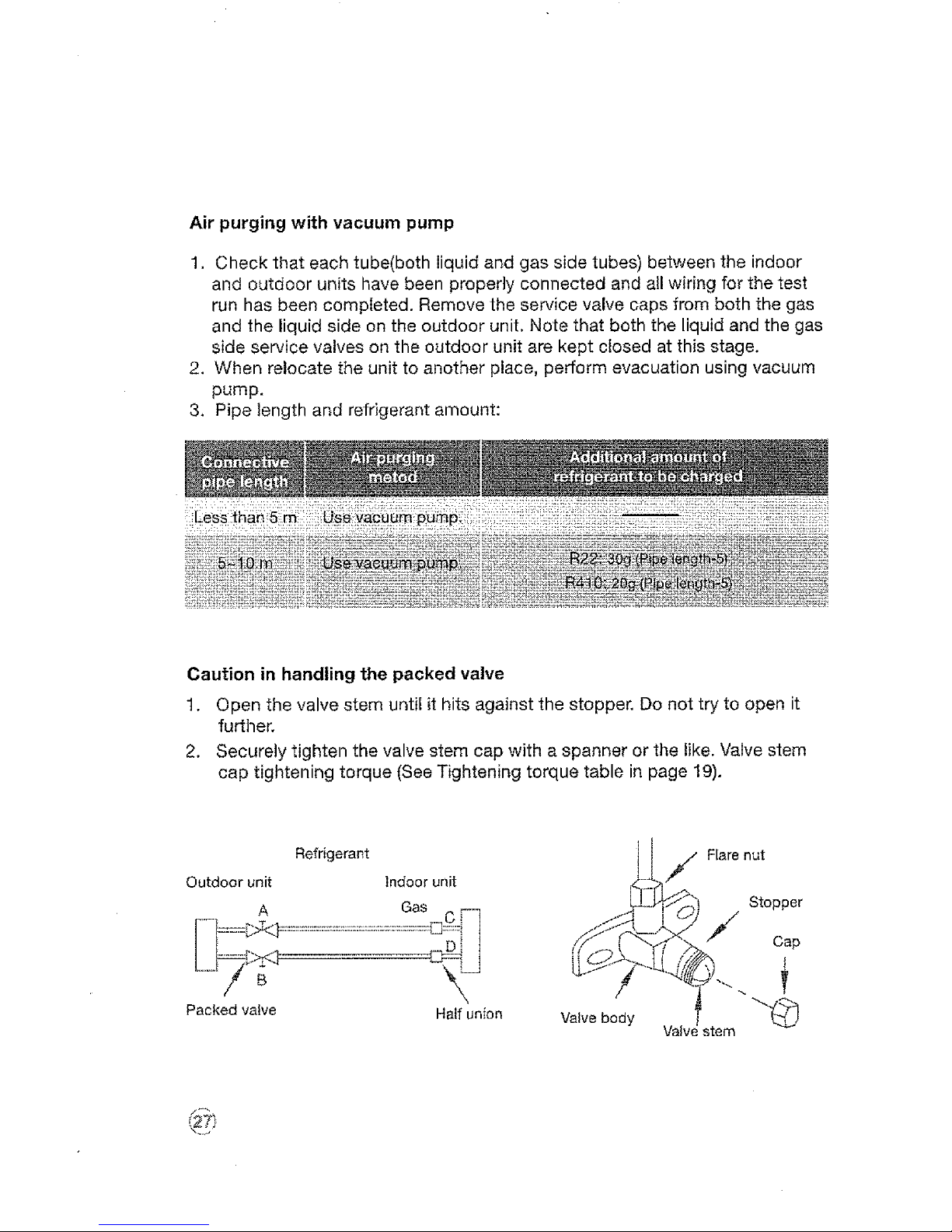
3, Pipe length and refrigerant amount:
Caution in handling the packed valve
t. Open the valve stem untie it hits against the stopper. Do not try to open it
further.
2. Securely tighten the valve stem cap with a spanner or the like. Valve stem
cap tightening torque (See Tightening torque table in page 19).
Refrigerant
Outdoorunit Indoorunit
A Gas _
-- _ mL* i
\
Packed valve Half unfon
Valve body
Flare nut
Stopper
/ Cap
Valw stem
@
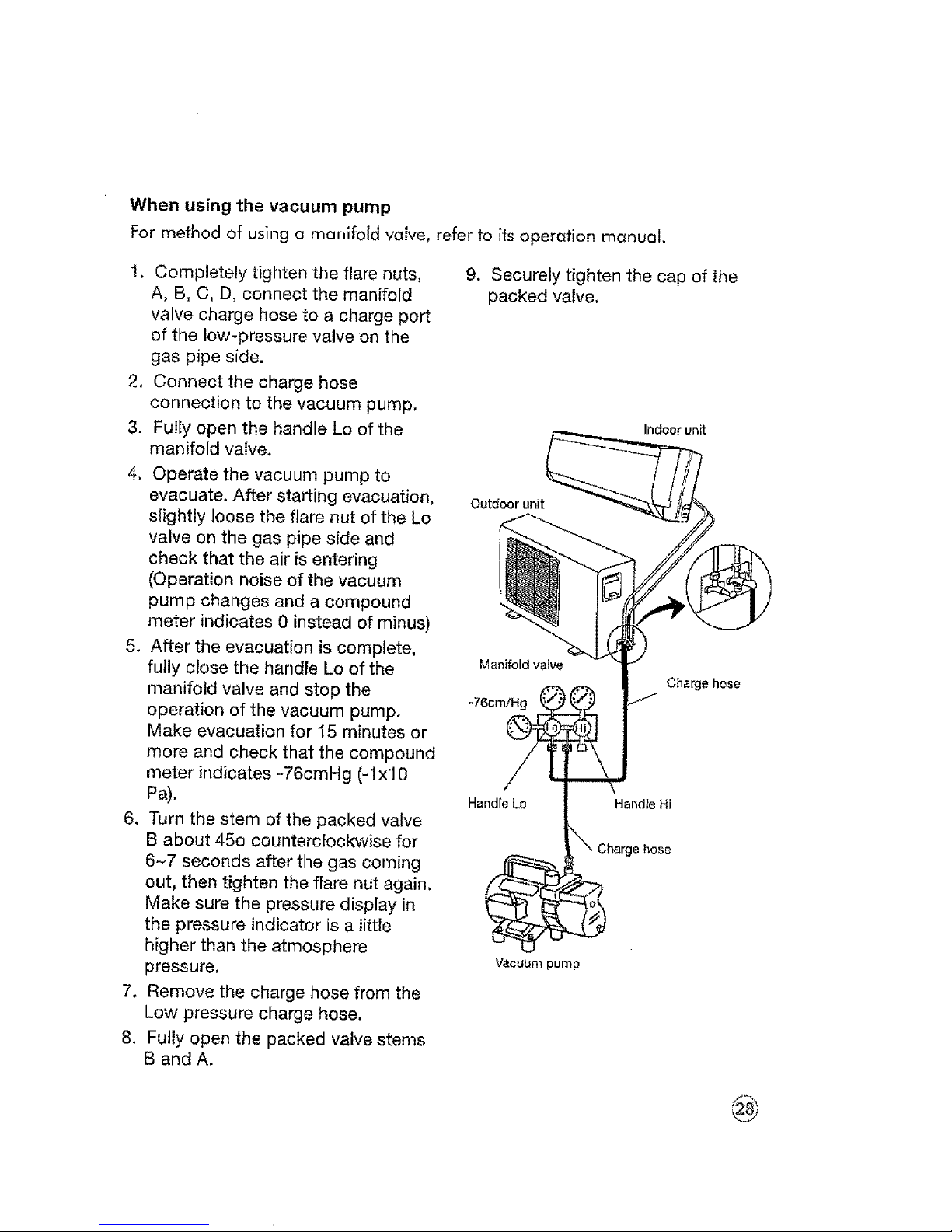
When using the vacuum pump
For method of using a manifold valve, refer to its operation manual.
I. Completely tighten the flare nuts,
A, B, C, D, connect the manifold
valve charge hose to a charge port
of the low-pressure valve on the
gas pipe side.
2, Connect the charge hose
connection to the vacuum pump,
3. Fully open the handle Lo of the
manifold valve,
4. Operate the vacuum pump to
evacuate. After starting evacuation,
slightly loose the flare nut of the Lo
valve on the gas pipe side and
check that the air is entering
(Operation noise of the vacuum
pump changes and a compound
meter indicates 0 instead of minus)
5. After the evacuation is complete,
fully close the handle Lo of the
manifold valve and stop the
operation of the vacuum pump,
Make evacuation for I5 minutes or
more and oheck that the compound
meter indicates -76cmHg (-Ix10
Pa),
6, Turn the stem of the packed valve
B about 45o counterclockwise for
6-7 seconds after the gas coming
out, then tighten the flare nut again,
Make sure the pressure display in
the pressure indicator is a little
higher than the atmosphere
pressure,
7. Remove the charge hose from the
Low pressure charge hose.
8. Fully open the packed valve stems
B and A.
9, Securely tighten the cap of the
packed valve,
Indoor unit
Outdoor unit
Charge hose
Har_dieLo
Handle Hi
_. Charge hose
'vacuum pump
@
Electrical safety
Perform the electric safe check after completing installation:
1. Insulated resistance: The insulated resistance must be more than 2M_.
2. Grounding work: After finishing grounding work, measure the grounding
resistance by visual detection and grounding resistance tester. Make sure the
grounding resistance is less than 4_.
3. Electrical leakage check (performing during test running): During test
operation after finishing installation, the serviceman can use the electroprobe
and mu[timeter to perform the electrical leakage check. Turn off the unit
immediately if leakage happens. Check and find out the solution ways till the
unit operate properly.
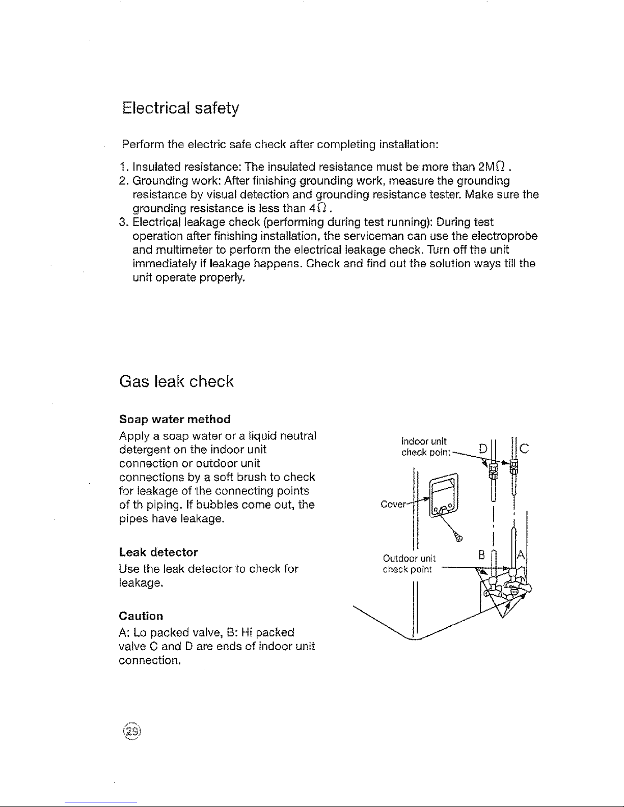
Gas leak check
Soap water method
Apply a soap water or a liquid neutral
detergent on the indoor unit
connection or outdoor unit
connections by a soft brush to check
for leakage of the connecting points
of th piping. If bubbles come out, the
pipes have leakage.
Leak detector
Use the leak detector to check for
leakage,
Caution
A: Lo packed valve, B: Hi packed
valve C and D are ends of indoor unit
connection.
indoor unit
check point _.._
Cover__
Outdoor unit B
check point ........... -_J._

Test running
Perform test operation after completing gas leak check at the flare nut
connections and electrical safety check,
1. Connect the power, press the ON/OFF button on the remote controller to
turn the unit on.
2. Use the MODE button to select COOL, HEAT, AUTO and FAN to check if all
the functions works well.
3. When the ambient temperature is too low(lower than 17°C), the unit cannot
be controlled by the remote controller to run at cooling mode, manual
operation can be taken. Manual operation is used only when the remote
controller is disable or maintenance necessary'.
_,_ [ Auto/CooiO
- Manual control button
Manual co
u.oo
Auto o I
Cool ® I
®

Preparing the device for operation
1. Contact a specialist to install the device.
2. Guarantee that the unit is appropriately fastened and complies with all of the
aforementioned safety norms.
3. Before operating the air conditioner, ensure that the air filter is installed
correctly.
4. If the unit has been out of use for a long period of time, it is recommended
that the air filter be cleaned before use. During continuous use, clean the air
filter every two weeks.
5. This air conditioner was designed for use under the following conditions:
::::Room Temperature: i:i::i
* (-5°C~43°C cooling only)
Attention
If air conditioner is used outside of the above conditions, certain safety
protection features may come into operation and cause the unit to function
abnormally.
Room relative humidity less than 80%. If the air conditioner operates in excess of
this figure, the surface of the air conditioner may attract condensation. Please
sets the vertical air flow louver to its maximum angle (vertically to the floor), and
set HIGH fan mode.
Optimum performance will be achieved within these operating temperature.
(3"t_

Product description
Front panel frame
Front panel
Air filter
(inside front panel)
Horizontal airflow grille
Vertical airflow grille
• _ Temperature sensor
(inside front panel)
Panel
Infra-red signal receiver
Drain hose connector and
refrigerant gas connector
Remote control
Connector cable
Detection valve
Drain hose and refrigerant
connecting pipe
Air iniet
#
Indoor
Air outlet
Air inlet
Attention
All the pictures in this manual are for
explanation purpose only. They may be
slightly different from the air conditioner
you purchased.
Air outlet
Outdoor unit

Display panel
(indoor unit)
_ AUTO indicator; This indicator
illuminates when the air conditioner
is in AUTO operation.
_ DEFROST indicator (For Cooling
& Heating models only): This
indicator illuminateswhen the air
conditioner starts defrosting
automatically or when the warm air
control feature is activated in
heating operation.
FAN**: The indicator will flash
when is in Fan mode only.
**Note: Only for models with
Cooling only and > 18,000 Btu's
INFRA-RED SIGNAL RECEIVER
_ DIGITAL SCREEN: Show the
present adjustments to
temperature when air conditioner is
operating.
OPERATION indicator: This
indicator flashes after power is on
and illuminates when the unit is in
operation.
TIMER indicator: This indicator
illuminates when TIMER is set
O N/O FE
Attention
The description in the control is based
on a typical model. The functions are
the same in your air conditioner, even if
there are some differences in the
appearance.

Remote control
Remote control operation
t. Operation mode: Cool, Heat (Only for the
models with cool/heat), DRY, FAN, and
AUTO (Automatic).
2. Timer 24 hrs.
3, Internal temperature range selection: 17°
- 30o.
4. LCD
5. Night light operation mode.
*(with 3 V,it reaches t 1 m)
A ttention
1. The air conditioner will not operate when curtains, doors our other materials
block the signals between the remote control and the indoor unit.
2. Avoid spilling any liquid in the remote control. Do not expose to sunlight or
any heat source.
3. If the infrared signal receiver inthe indoor unit is exposed to sunlight, the
air conditioner unit might not work properly. Use curtains or shades to
avoid having sunlight directly to the receiver.
4. If other electrical equipment react to the signals sent by the remote control,
change the position or consult with you local sales department.

Remote control battery
Touse the remote control, it is
necessary to install two (R03/Ir03x2)
alkaline AAA batteries.
When should the batteries be
replaced
1. When there is not a "beep"
anymore from the indoor unit when
using the control remote or the
signal light indicator does not lit.
2. The indoor unit does not respond
to the remote control commands to
activate the programs.
conditioner emits a "beep" that
indicates that a command has been
received and transmitted in the
indoor unit.
3. When selecting the function of
timer, the remote control sends
(automatically) a signal to the indoor
unit at the specific moment. If the
control remote is left in a position
that the signal is blocked, a 15
minute delay can be produced.
To replace batteries
1. Slide out the battery compartment
cover (located in the back part of
the remote control).
2. install the two AAA batteries in the
compartment (indicated in the
drawing located inside the
compartment).
3. Slide in the cover.
4. If the remote control is not
operated for long period of times,
batteries should be discarded.
Remote control instructions
1. The signal reach distance of the
remote control to the receiver that
is inside the main unit of the air
conditioner is 8 meters. Any
obstruction placed between the
receiver and the remote control can
cause interference, limiting the
capacity of the programming.
2. Any time that a button is pressed
in the remote control, the air
Attention
1. When replacing batteries, do not
use old batteries or a different type
battery. This may cause the remote
control to malfunction.
2. If you do not use the remote
controller for several weeks remove
the batteries. Otherwise battery
leakage may damage the remote
controller,
3. The average battery life under
normal use is about 6 months,
4. Replace the batteries when there is
no answering beep from the indoor
unit or if the Transmission indicator
light fails to light.

Remote control description
ON/OFF: Push this button to start
the unit operation. Push the button
again to stop the unit operation,
TEMP_: Press the button to
increase the indoor temperature
setting.
TEMPV: Press the button to
decrease the indoor temperature
setting.
SWING: Push this button, the louver
would swing up and down
automatically. Push again to stop it.
CLOCK: is used to select the time.
TURBO*: Press this button on
cooling/heating** mode to go into
powerful cooling (heating)operation.
Press againto cancel it,
*Note 1: Only for some models.
**Note 2: For models with PTC only.
MODE: Each time you push the
button, a mode is selected in a
sequence that goes from AUTO,
COOL, DRY, HEAT*, and FAN, as
the following figure indicates:
AUTO_.COOLi_DRYI_ HEAT* I_ FAN
t J
FAN SPEED: This button is used for
setting Fan Speed in the sequence
that goes from AUTO, LOW, MED to
HIGH, then back to Auto.
AUTO 1_ LOW I_ MED I_ ALTA
Attention
* Note: Only for heating and cooling
models.

_ SLEEP; This button is used to
start or stop the sleep function
and/or to start the block function.
Also, press this button once and
the unit starts operating in sleep
mode which keeps the room
temperature comfortable and
helps in the consumption of
energy. To start the block function
press this button for 3 seconds;
and it will start leaving the
configuration and it won't accept
in operation except for the present
block function.
_ TIMER: Is used to select the
turning on time and turning off
time of the air conditioner.
_ CANCEL:
1. If the timer is TIMER ON/TIMER
OFF and the function has been
configured, press "cancel" and
it will cancel the timer program
and turn off the unit.
2. If the timer is "TIMER OFF"
only mode, press the button
"Cancel" and it will cancel the
timer program and turn the unit
off.
Note: This function, works only
when some function of timer is
activated, tn the contrary, nothing
will happen when the button is
pressed.
LED (screen): Press this button
to erase the digits that are shown
in the screen of the air conditioner.
Press again to activate,
@

LCD display indicators
Auto air speed
Air speed indicator
®
Turbo*
Sleep
ON/OFF indicator: This
indicator lit and flash once the
remote control sends the signal
to the indoor unit.
Auto mode
Cool mode
Dry mode
Heat mode
Fan mode
Auto clean*
AUTO
CLEAN
2H _ Temperature display
Block
t Horizontal airflow (up/down)*
Vertical airflow(left/right)*
_n Timer set
f,J ,"U U
Attention
All the items are shown in the screen to have a clear and precise explanation.
But only the actual function items will be shown in the visualization panel.
*During the actual operation, this indicator will not be shown in the panel of the
indoor unit.

How the air conditioner works
Automatic operation
When the Air Conditioner is ready for use, switch on the power and the
OPERATION indicator lamp on the display panel of the indoor unit starts
flashing.
I. Use the MODE .select button to select AUTO.
2. Push the TEMP button to set the desired room temperature. The most
comfortable temperature setting are between 21°C o to 28°C.
3. Push the ON/OFF button to start the air conditioner. The OPERATION lamp
on the display panel of the indoor unit lights. The
operating mode is AUTO FAN SPEED is automatically set and there are no
indicators shown on the display panel of the remote controller.
4. Push the ON/OFF button again to stop the unit operation.
Attention
1. When you set the air conditioner in AUTO mode, it will automatically select cooling,
heating(cooling/heating models only), or fan only operation depending on what
temperature you have selected and the room temperature.
2. The air conditioner will control room temperature automatically round the
temperature point set by you.
3. If the AUTO mode is uncomfortable, you can select desired conditions manually.
COOL / HEAT and FAN ONLY operation
1. if the AUTO mode is not comfortable, you may manually override the settings
by using COOL, HEAT* or FAN** ONLY modes.
2, Push the TEMP button to set the desired room temperature. When in COOL
mode, the most comfortable settings are 21°C or above. When in HEAT
mode, the most comfortable settings are 28 C or b elow.
3. Push the FAN SPEED to select the FAN mode of AUTO, HIGH, MED or LOW.
4. Push the ON/OFF button, the operation lamp lights and the air conditioner
start to operate as your settings. Push the ON/OFF button again to stop this
unit operation.
* Nota: Only for heating and cooling models
"*Note: The FAN ONLY mode can not be used to control the temperature.
While in this mode, only steps 1,3 and 4 may be performed.

DRYoperation
Thedrymodewillautomaticallyselect
thedryingoperationbasedonthe
differencebetweentheset
temperatureandtheactualroom
temperature,
Thetemperatureisregulatedwhile
dehumidifyingbyrepeatingturningon
andoffofthecoolingoperationorfan
only,ThefanspeedisLOW.
1.PushtheMODEbuttontoselect
DRY,
2. PushtheTEMPbuttontosetthe
desiredtemperaturefrom21°Cto
28°C.
3. PushtheON/OFFbutton,the
operationlamplightsandtheair
conditionerstarttooperateinthe
DRYmode,FANSPEEDisLow,
PushtheON/OFFbuttonagainto
stopthisunitoperation.
Attention
Due to the difference of the set
temperature of the unit and the
actual indoor temperature, the Air
Conditioner when in DRY mode will
automatically operate many times
without running the COOL and FAN
mode.
# # o
Set temperature
DRY Function
Air flow direction adjustment
Use SWING to adjust the airflow direction up and down,
1. When swing is pressed the horizontal louver moves up and down
automatically. Press again to stop operation
Attention
if the louver oscillates or moves in a position that could affect the cooling or
heating ofthe air conditioner the direction of the oscillation/movement would
alter automatically.

SLEEP mode
Press the sleep button to activate the
sleep mode. To deactivate, press the
button again.
Cool only mode:
• The indoor unit fan operates at a
low velocity.
• After and hour of operation, the
adjusted temperature will increase
1° C. After, the unit keeps
operating 2°C above the adjusted
temperature.
In heating mode (some models):
• The indoor unit fan operates at a
low velocity.
• After and hour of operation, the
adjusted temperature will decrease
1° C. After, the unit keeps
operating 2° C below the adjusted
temperature.
Attention
Sleep function is only availaib[e in the
Coot/Heat and AUTO mode.
+l J--J S,°o
Ee
SLEEP FUNCTION (Cooling mode)
oo
I
I
SLEEP FUNCTION (Heating mode)
TIMER Operation
TIMER button can set the auto-on time of the unit.
To set the starting time
1. Push the TIMER ON button, then the remote controller shows TIMER ON,
the last set time for the starting operation and the signal "h" will be shown on
the DIGITAL DISPLAY area. You are now ready to reset the time to START the
operation.
2, Push the TIMER ON button again to set desired unit start time,
3. After setting the TIMER ON ,there will be a one-half second delay before the
remote controller transmits the signal to the air conditioner. Then, after
approximately another 2 seconds, the signal "h"disappears and the set
temperature will re-appear on the digital display.

To set the stopping time
1. Push the TIMER OFF button and the remote controller will show TIMER OFF,
the last set time for the stopping operation and the signal "h"wilt be shown
on the DIGITAL DISPLAY area. You are now ready to reset the time of the
STOP operation,
2. Push the TIMER OFF button again to set the time you want to stop the
operation.
3. After setting the TIMER OFF ,there will be a one-half second delay before the
remote controller transmits the signal to the air conditioner. Then, after
approximately another 2 seconds, the signal "h" disappears and the set
temperature will re-appear on the digital display.
Exernples:
ON ON
6h 6h
(T_mp On) (Te r_p Off)
ON ON ONN
....oFLJ
= ,, . = ,,.....>
12h 14h 20h 23h
('rempOf0 (TeTepOn) (Temp On) {Temp Off)
Optimal operation
To achieve optimal performance, please note the following:
1. Adjust the air flow direction correctly so that it is not directed on people.
2. Adjust the temperature to achieve the highest comfort level. Do not adjust
the unit to excessive temperature levels.
3. Close doors and windows on COOL or HEAT modes, or performance may be
reduced.
4. Use TIMER ON button on the remote controller to select a time you want to
start your air conditioner.
5. Do not put any object near air inlet or air outlet, as the efficiency of the air
conditioner may be reduced and the air conditioner may stop running.
6. Clean the air filter periodically, otherwise cooling or heating performance may
be reduced.
7. Do not operate unit with horizontal louvre in closed position.
@

How to use the indoor unit
Adjusting air flow direction
Adjust the air flow direction properly
otherwise, it might cause discomfort
or cause uneven room temperatures.
Adjust the horizontal louver using the
remote controller. Adjust the vertical
louver manually.
Adjusting the vertical air flow
direction (up - down)
The air conditioner automatically
adjusts the vertical air flow direction in
accordance with the operating mode.
To set the horizontal air flow
direction (left! right)
Adjust the vertical louver manually
using the lever on the left or right side
of the vertical louver arm (Depending
on model). Take care not to catch
fingers on the fan, horizontal louver or
to damage vertical louvers. When the
air conditioner is in operation and the
horizontal louver is in a specific
position, move the lever at left (or
right, depending on model) end of the
air outlet to the desired position.
To automatically swing the air flow
direction (up/down)
Perform this function while the air
conditioner is in operation,
Press the SWING button on the
remote controller.
To stop the function, press the
SWING button again.
Press AIR DIRECTION button to lock
louver in desired position.
%
Lever

The AIR DIRECTION and SWING buttons
will be disabled when the air conditioner
is not in operation (including when the
TIMER ON is set).
Do not operate the air conditioner for
long periods with the air flow direction set
downward in cooling or dry mode.
Otherwise, condensation may occur on
the surface of the horizontal louver
causing moisture to drop on to the floor
or on furnishings.
Do not move the horizontal louver
manually. Always use the AIR DIRECTION
or SWING button. If you move this louver
manually, it may malfunction during
operation, If the louver malfunctions, stop
the airconditioner once and restart it.
When the air conditioner is started
immediately after it was stopped, the
horizontal louver might not move for
approximately 10 seconds.
Open angle of the horizontal louver
should not be set too small, as COOLING
or HEATING performance may be
impaired due to too restricted air flow
area.
Do not operate unit with horizontal louver
in closed position.
When the air conditioner is connected to
power (initia_power), the horizontal louver
may generate a sound for 10 seconds,
this is a normal operation.

Manual operation (without remote control)
Manual operation can be used
temporarily in case you can not find
the remote controller or its batteries
are exhausted.
!. Open and lift the front panel up to
an angle until it remains fixed with
a clicking sound,
2. One press of the manual control
button will lead to the forced
AUTO operation.
3. Close the panel firmly to its
original position.
Attention
Once you push the manual button,
the operation mode is shifted in an
order as: AUTO, COOL, OFE
Push the button twice, the unit will
operate in forced COOL mode. This is
used for testing purposes only.
Third press will stop the operation and
turn off the air conditioner operation.
To restore the remote controller
operation, use the remote controller
directly.
@
Manual control
button /
Auto/Cool@

Maintenance
Cleaning the indoor unit and remote
controller
1. It is necessary to stop the air
conditioner and disconnect the power
supply before cleaning.
2, Use a dry cloth to wipe the indoor unit
and remote controller,
3, A cloth dampened with cold water
may be used on the indoor unit if it is
very dirty.
4. The front panel of the indoor unit can
be removed and cleaned with water.
Then wipe it with a dry cloth.
5. Do not use a chemically treated cloth
or duster to clean the unit.
6. Do not use benzine, thinner, polishing
powder, or similar solvents for
cleaning. These may cause the plastic
surface to crack or deform.
Cleaning the air filter
A clogged air filter reduces the cooling
efficiency of this unit. Please clean the
filter once every 2 weeks,
1. Lift the indoor unit panel up to an angle
until it stops with a clicking sound.2.
Take hold of the handle of the air filter
and lift it up slightly to take it out from
the filter holder, then pull it
downwards.
3. Remove the air filter (Fresh air filter +
support) of the unit.
4. Remove fresh air filter from frame
support.
5. Clean the fresh air filter at least once a
month, and replace every 4 to 5
months. Use a vacuum cleaner, then
dry.
6. Clean the support frame using a
4b
Air filter
Air filter

vacuum cleaner or water, After, dry
for a couple of hours or until dry.
7. Insert the fresh air filter in its original
place.
8. insert the high part of the air filter
(fresh air filter + Support frame)
again in the unit keeping in mind
that the outside border (right and
left) are lined up correctly, now
place the whole filter in the initial
position,
Support
Fresh frame
air filte_
Fresh
air filter
Fig.1 Fig.2
Support
frame
Fresh _\
air flits
Fig.3 - "\\ _"_
Suppo_
frame
Maintenance
Ifyou plan to idle the unit for a long time, perform the following:
1. Operate the fan for about half a day to dry the inside of the unit.
2. Stop the air conditioner and disconnect power. Remove the batteries from
the remote controller.
3. The outdoor unit requires periodic maintenance and cleaning. Do not
attempt to do this yourself. Contact your dealer or servicer.
Checks before operation
1. Check that the wiring is not broken off or disconnected.
2, Check that the air filter is installed
3. Check if the air outlet or inlet is blocked after the air conditioner has not
been used for a long time.

Operation tips
The following events may occur during normal operation.
Protection of the air conditioner,
Compressor protection
The compressor can't restart for 3 minutes after it stops.
Anti-cold air (Co..o!ingand heating models only)
The unit is designed not to blow cold air on HEAT mode, when the indoor heat
exchanger is in one of the following three situations and the set temperature
has not been reached.
1. When heating has just starting.
2. Defrosting.
3. Low temperature heating.
Defrosting (Cooling and heatinq models on[v)
Frost may be generated on the outdoor unit during heat cycle when outdoor
temperature is low and humidity is high resulting in lower heating efficiency of
the air conditioner. During this condition air conditioner wilt stop heating
operation and start defrosting automatically.
The time to defrost may vary from 4 to 10 minutes according to the outdoor
temperature and the amount of frost buildup on the outdoor unit.
The indoor or outdoor fan stop running when defrosting (Cooling and heating
models only).
A white mist coming out from the indoor unit
A white mist may generate due to a large temperature difference between air
inlet and air outlet on COOL mode in an indoor environment that has a high
relative humidity.
A white mist may generate due to moisture generated from defrosting process
when the air conditioner restarts in HEAT mode operation after defrosting.
Low noise of the air conditioner
You may hear a low hissing sound when the compressor is running or has just
stopped running.
This sound is the sound of the refrigerant flowing or coming to a stop.
You can also hear a low "squeak" sound when the compressor is running or
has just stopped running. This is caused by heat expansion and cold
contraction of the plastic parts in the unit when the temperature is changing.
A noise may be heard due to louver restoring to its original position when
power is first turned on.
Dust is blown out from the indoor unit.
This is a normal condition when the air conditioner has not been used for a long
time or during first use of the unit.
_Y

Apeculiarsmellcomesoutfromtheindoorunit.
Thisiscausedbytheindoorunitgivingoffsmellspermeatedfrombuilding
material,fromfurniture,orsmoke.
TheairconditionerturnstoFANonlymodefromCOOLorHEAT(For
coolingandheatingmodelsonly)mode.
Whenindoortemperaturereachesthetemperaturesettingonairconditioner,the
compressorwillstopautomatically,andtheairconditionerturnstoFANonly
mode.Thecompressorwillstartagainwhentheindoortemperatureriseson
COOLmodeorfallsonHEATmode(Forcoolingandheatingmodelsoly)tothe
setpoint.
Drippingwatermaygenerateonthesurfaceoftheindoorunitwhencoolingina
highrelativelyhumidity(relativehumidityhigherthan80%).Adjustthehorizontal
louvertothemaximumairoutletpositionandselectHIGHfanspeed.
Heatingmode(Forcoolingandheatingmodelsonly)
Theairconditionerdrawsinheatfromtheoutdoorunitandreleasesitviathe
indoorunitduringheatingoperation.Whentheoutdoortemperaturefalls,heat
drawninbytheairconditionerdecreasesaccordingly.Atthesametime,heat
loadingoftheairconditionerincreasesduetolargerdifferencebetweenindoor
andoutdoortemperature.Ifa comfortable temperature can't be achieved by the
air conditioner, we suggest you use a supplementary heating device.
Auto-restart function
Power failure during operation will stop the unit completely.
For the unit without Auto-restart feature, when the power restores, the
OPERATION indicator on the indoor unit starts flashing. To restart the operation,
push the ON/OFF button on the remote controller. For the unit with Auto-restart
feature, when the power restores, the unit restarts automatically with all the
previous settings preserved by the memory function.
Lightning or a car wireless telephone operating nearby may cause the unit
to malfunction.
Disconnect the unit with power and then re-connect the unit with power again.
Push the ON/OFF button on the remote controller to restart operation.

Solutions for problems
If your air conditioner malfunctions, check the following information to find
solutions or probable causes of the failure. Do not try to repair the unit by
yourself, if these solutions do not solve the failures; call your local service repair
team.
Poor Equipment performance
1. The air outlet or inlet in the exterior part is obstructed,
2. The temperature in the exterior is high due to direct sunlight or another heat
source.
3. Heater or a cooking stove is being used in the same room.
4. Room is full of people.
5. The air filter is obstructed by dust or is dirty.
6. Inappropriate temperature adjustment,
7. Front part is obstructed.
8. The capacity of the equipment is not adequate for the size of the room.
9. Air conditioner was just turn on.
10,Windows or doors are open.
11.Motor protector has been activated.
The unit does not start
1. The plug is not connected to the outlet.
2. No electricity in the outlet.
3. The voltage is different.
4. Temperature is not adjusted properly.
5. burned fuse,
6. The remote control batteries need to be replaced.
7, wrong operation time.
Attention
Stop the air conditioner immediately if one of the following malfunctions occur
1. The operation indicator or other indicator flash(5times persecond) and the flashing is
not stop by disconnecting and connecting the unit,
2. Frequentchange of fuses and malfunctions in the switch circuit.
3. Water spills over the equipment,
4. Remotecontrol does not work,
5. Any other abnormal situation,
®

Technical specifications
COOLING MODELS
HEATING + COOLING MODELS

Notes
@

Notes

Notes
_!_ii_i!_i_i_!!_i!!_i!_!i_i_i_!!i_i_!i!!_i_i_!_!i!_!_!_iii_i_!_i_ii_!!_!i!_!_i_!i!_ii_iii!i!_ii_i_!_i_ii_i_!!_!!i_!_:_ii_ii_!i_i!_ii!_i!_i_ii!i_i!_!i_ii_i!_iii_!i!_i_

ii:_ii!iil}i_i:i_iiiiii_!iiii:iiii:i:ii_iiiii?ii_ili$i:ili_i!!i_¸_ii_ii_iiii_i_i_ii_!!_ii!_i_!ii_{ii{_i_i_!_{i_ii_ii_iiiii!!_iii_!ii_ii_!iiiiiii_i{i_i_ii_i_iiii!_i_i_i!_i_!iii_ii_i!_i_iiiiii_i_ii!_iiiiii_iiii_ii_iiii
"_i:_ _ii;__i_!,_i_ii:i_!}ii_iii_i_iiiii_!!ii!_!i_ii_i£,_iii_Z___ _ __i_ii_i_!iiKii_iii_i!_i_!_iiii_i
FRIGI D_! R _ii_,,_;_

FRIGIDAIR
ATENCION
Lea todas las instrucciones antes de
utilizar el aparato y guardelas para futuras

Bienvenido al mundo dei
manejo simple y sin preocupaciones
Gracias por elegir Frigidaire como marca para su acondicionador de aire.
Los acondicionador de aire Frigidaire han sido concebidos bajo altisimos
est&ndares t_cnicos. Poseen caracteristicas especiales desarrolladas para
ofrecer aun m,'_scomodidad al usuario.
Para que usted pueda disfrutar todos los recursos que su nuevo
acondicionador de aire ofrece, Frigidaire cre6 este manual. Con orientaciones
simples y pr&cticas usted conocera sus funciones y aprenderA ]a manera de
operar este aparato de modo adecuado y seguro.
Lea las instrucciones sobre instalaci6n y operaci6n antes de utilizar su
acondicionador de aire y gu&rdelas en un lugar seguro para futuras consultas.
Frigidaire una vez mAs fabrica Io mejor en Io que se refiere a
electrodomesticos.
Consejos ambientales
E! material deI embalaje es reciclable.
Procure separar pl&sticos, espuma flex,
papeI y cart6n y enviarlos alas
compaSias de recictaje.
De acuerdo con la directriz de la RAEE
(Residuos de Aparatos El6ctricos y
Electr6nicos), en ingles WEEE (Waste of
Electrical and Electronic Equipment), se
debe colectar y disponer de los residuos
de aparatos el6ctricos y etectr6nicos
separadamente. Si futuramente usted
necesita desechar este electrodom6stico,
NO Io haga echandolo con el resto de la
basura dom6stica. S[rvase enviar el
aparato a los puntos de colecta de RAEE
donde los haya disponibles.

Indice
01. Bienvenido ........................................................................................... 01
02. Consejos ambientales .......................................................................... 0I
03. indice ................................................................................................... 02
04. Precauciones de seguridad ..................................................................... 04
05, Instalaci6n:
5.1 Eligiendo el local de instalaci6n .................................................. 08
5.2 Lista de piezas ............................................................................ 10
5.3 instalaci6n de la unidad interna ................................................... 12
5.4 Instalaci6n de [a unidad externa .................................................. 17
5.5 Conexi6n de ta tuberia refrigerante .............................................. 19
5.6 Conexi6n ei6ctrica ..................................................................... 21
5.7 Purga de aire ............................................................................. 26
5.8 Seguridad el_ctrica .................................................................... 29
5.7 Control de fuga de gas............................................................... 29
5.8 Prueba de funcionamiento ......................................................... 30
06. Operaci6n:
6.1 Preparando el aparato para hacerlo funcionar. ............................. 31
6.2 Descripci6n del producto ........................................................... 32
6.3 Como funciona et control remoto ................................................ 34
- Caracteristicas del control rernoto
- Cargar el control remoto
- Se deber_ sustituir las pilas cuando:
- Para sustituir las pilas:
- Instrucciones de uso del control remoto
6,4 Descripci6n del control remoto .................................................... 36
- Encender/apagar
- Mas (Temperatura)
- Menos (Temperatura)
- Swing
- Clock
- Turbo
- Modo
- Vent. (velocidade deI ventilador)
- Dormir
- Temporizador
- Cancel
- LED (Pantalla)
6,5 Indicadores en la pantalla LCD................................................... 38
6.6 Como funciona el acondicionador de aire ................................... 39
- Operaci6n Auto (Autom_.tica)
- Operaci6n Auto (autom&tica)
@

- Operaciones Frio, Calor Y Solo Vent.
- Uso de la deshumidificaci6n - Seco (Dry)
- Ajuste de la direcci6n del flujo de aire
- Uso de Dormir
- Operaci6n del Temporizador (Timer)
- Funcionamiento 6ptimo
6.7 Como usar la unidad interna ...................................................... 43
- Ajuste la direcci6n de! flujo del aire
- Ajuste de la direcci6n del aire verticalmente (arriba/abajo)
- Para ajustar la direcci6n horizontal (izquierda/derecha)
- Para ajustar la direcci6n horizontal (izquierdaiderecha)
- Para operar la funci6n SWING (arriba/abajo)
6.8 Operacion manual (sin control remoto) ...................................... 45
07. Mantenimiento y cuidados .................................................................... 46
08. Consejos de operaci6n ......................................................................... 48
09. Guia para la soluci6n de problemas ...................................................... 50
10. Especificaciones tecnicas ...................................................................... 51
Atenci6n
1. El aparato que usted ha comprado puede set tigeramente diferente del que
se muestra en las figuras de este manual, la forma en general deber4 ser la
misma.
2. Este acondicionador de aire ha sido proyectado para uso domestico. No
se recomienda su uso para fines comerciales, industriales yio en
laboratorios.
3. El aparato que usted ha comprado puede tenet un enchufe diferente del
que se muestra en las figuras de este manual, siendo que el que viene en
el producto cumple la especificaci6n el6ctrica de su pals.

Precauciones de seguridad
Normas de seguridad
Las siguientes normas deberAn ser siempre respetadas para mayor seguridad:
° Aseg_rese de leer las siguientes advertencias antes de instalar el
acondicionador de aire.
• Aseg_rese de seguir todas las precauciones especificadas aqui, ya que
incluyen importantes terminos relativos a [a seguridad,
1. El acondicionador de aire debe
estar conectado a tierra. Si no Io
est& completamente puede haber
choques el6ctricos, No conecte eJ
cable tierra al tubo de conexi6n, a
la tuberia de agua, barra de Iuz,
tierra del telefono. Despu_s de la
instalaci6n, verifique que no haya
fugas.
2. Utilice los cables especificados
para conectar las unidades intema
y extema con seguridad y conecte
los cables firmemente alas
secciones de la placa de los
bornes para que las tensiones no
se apliquen a las secciones. La
conexi6n o co]ocaci6n incorrecta
podria originar fuego.
3. No haga funcionar ni detenga la
unidad enchuf&ndolo por el cable
de alimentaci6n o tirando del cable
de alimentaci6n. Desconecte el
cable de alimentaci6n sujet&ndolo
por el enchufe,
4. No modifique el cable de
alimentaci6n el@ctrica ni utilice et
mismo tomacorriente para
conectar otros electrodom@sticos.
Peligro de descarga el_ctrica o de
incendio causado pot producci6n
excesiva de cator.

5. Noda_eniutiliceuncablede
alimentaci6net6ctricano
especificadeparaelproducto.Si
elcabledealimentaci6nest&
da_ado,elfabricante,suagente
demantenimientoosimilar
personaautorizadadeber_
substituirloparaevitarelpeligro
queelcablerepresenta,
6. I',1ouseeltomacorrientesiesta
flojoodaSado.
7. Instalesiempreuninterruptor
autom_.ticoyuncircuitode
alimentaci6nexctusivoparael
aparato.
8. Nodirijaelflujodeaireenla
direcci6ndelosocupantesdela
habitaci6n,esdaSinoparaIa
salud.Potlosmisrnosmotivos,
tampocoexpongaplantaso
animalesalflujodirectodelaire.
9. Desenchufeelaparatocuandono
1ovayaausarporunlargoperiodo
detiempo,elac[3mulodesuciedad
podriacausarfuego.
10.Instaleuninterruptorfusibledela
capacidadnominalparaevitar
posibleschoquesel6ctricos,
11.Cuandovayaalimpiarlaunidad,
descon_cteladeltomacorrientey
desconectetambienelinterruptor
autom&tico,l',Jolimpielaunidad
mientrasest&conectadapues
existepeligrodecausarun
incendio,descargasel6ctricaso
accidentes.

12.Nolimpieelacondicionadorde
aimconagua,Elaguapodria
penetrarenlaunidadydeteriorar
suaislamiento,adem_sdepeligro
dedescargasel6ctricas.
13. No maneje el aparato con las
manos mojadas o en lugares
hQmedos.
14. Cierre las puertas y ventanas
mientras el acondicionador de aire
est& funcionando por mucho
tiempo. Si necesita ventilar la
habitaci6n, abra la puerta o la
ventana por poco tiempo,
solamente para permitir la entrada
de aire fresco,
15. No ponga aparatos fuentes de
calor expuestos a las salida de
aire de[ acondicionador de aire,
debido a peligro de incendio.
I6, No instale el acondicionador de
aire en lugares en los que haya
gases inflamables o combustibles
como gasolina, benceno,
solventes, etc.
17. No utitice el acondicionador de
aire para otros propuestos como
atmac@nde equipos de precisi6n,
comida, pintura, etc., que
requieren ciertas condiciones de
temperatura y humedad, pues su
calidad se puede ver afectada.
18. No coloque los dedos o otros
objetos en las reji]las del panel
frontal, pues el ventilador girando
a alta velocidad podria causar un
accidente.
19. Desconecte la alimentaci6n
el6ctrica a la unidad si escucha
algt_n ruido anormal o siesta
emite olores o humo. H_galo
\

tambien en caso de tormenta o de
condiciones clim&ticas adversas.
20. No beba el agua drenada del
acondicionador de aire, esta
contiene agentes contaminantes
que pueden resultar daSinos para
la salud.
21. Cuando vaya a reemplazar el filtro
de aire, no toque las partes de
metal del aparato.
22. Antes de hacer funcionar el
aparato haga ventilar la habitaci6n
si ha habido algSn escape de gas
de otro aparato. En presencia de
estufas e otros aparatos fuente de
calor, ventile bien el recinto.
23. No abra el aparato durante el
funcionamiento.
24. No ponga objetos pesados sobre
el cable de alimentaci6n el6ctrica
y asegQrese de no aplastarlo.
25. No desarme ni modifique el
aparato.
26. Tome cuidado al desempacar y
instafar la unidad.
27. AsegOrese de que no entre agua a
los componentes el6ctricos,
28. Mantenga cualquier arma de
fuego alejada del
electrodomestico.
29. Siempre compruebe la instalaci6n
de los filtros y limpielos a cada
dos semanas. Hacer funcionar el
aparato sin los filtros puede
ocasionar averias.
30. No ponga objetos cerca de las
entradas o en las satidas de aire,
_07_

Eligiendo el local de instalaci6n
Precauciones para la instalaci6n
La instalaciSn en los siguientes lugares podria causar problemas. Si es
inevitable realizarla en algunos de estos lugares, por favor consulte con su
distribuidor local Electrofueguina.
1. Un lugar Ileno de aceites de m_tquina.
2. Lugares con alta concentraci6n de salinidad, como en la costa.
3. Lugares donde haya gas sulfOrico como por ejemplo balnearios de aguas
termales.
4. Lugares donde hay m&quinas de atta frecuencia como equipos inalAmbricos,
m&quinas de soldaduras e instalaciones m_dicas.
5. Un lugar con gases inflamables o material vol_.til.
6. Un lugar con condiciones ambientates especiales.
7. Lavadero
Unidad interna
1. Un lugar que no obstacuJice el
_rea de entrada o salida del aire.
2. Un lugar que soporte el peso de la
unidad interna.
3. Un lugar de facil acceso para
realizar el manteniemiento y el
oambio del filtro de aire en su
aparato.
4, Un lugar que provea los espacios
requeridos alrededor de la unidad
intema como se muestra en el
gr&fico abajo.
5. Un tugar que tenga pot Io menos
mas de un metro de distancia con
respecto a un televisor,
instrumentos de radio. En el centro
del lugar es perfecto.
6, Un lugar alejado deI fuego, humo y
gases inflamables,
7. La unidad interna debe estar
instalada por 1omenos a 2.3
metros por encima del piso.
8. Lugares donde el tubo de
conexi6n y la manguera de
desague sean f_ciles de sacar.
9. Lugar que evite el contacto directo
con los rayos solares.
M_s
de 12cm
M_s
de 15crn
¢@
Mas
de 12cm
M_s
de 200cm
Atencion
Recomendamos que ta unidad internana
no reciba Iuzdirecta del sol. De Io
contrario, el sol hara que se desvanezca e]
gabinete de pl,_sticoy esto podr&afectar
su apariencia. Si es inevitable que Ialuz
de sol entre directamente en contacto con
la unidad intern& las precauciones para
que el producto no se desvanezca no se
estar&ntomando en cuenta.

Unidad externa
1, Un ]ugar que sea conveniente para
la instalaci6n y no esta expuesto a
vientos muy fuertes. Un lugar seco
y ventilado.
2. Un lugar que soporte el peso de la
unidad externa y pueda ser
sostenida en posici6n vertical.
3, Un lugar que no permita un
incremento en el niveI de ruido y
vibraci6n.
4, Un lugar en donde el ruido
producido por el funcionamiento y
descarga del aire no moleste a sus
vecinos o animales.
5. Un lugar sin fugas de gases
inflamables.
6. Un lugar que permita una elevacion
de las tuberias no menor de 5
metros y con una Iongitud de
tuberias de pot Io menos 10
metros.
7. Lugares en los que haya espacio
suficiente en tomo de esta unidad,
como se muestra en el diagram&
8. Un lugar en donde los ni_os no
tengan acceso,
M_s
de 30cm
M_s
de 200cm
Mas
de 60cm
M_s
de 30cm
f
M&s
de 60cm

Lista de piezas
Unidad tnterna
Unidad Externa

MAs de 15cm
Unidad Interna
M&s de 12cm
Filtro _i 3
de Aire
MEs 0cm
M4sde 200cm
M_s de 12cm
M_s de 60cm
Mas
de 60cm
C
Unidad
Externa
Atenci6n
1. lnstale ]a unidad interna a una altura de no menos de 2 m. Un recorrido
minimo de 4 a 5 men las tuberias, requeddo para minimizar lavibraci6n y
el ruido en exceso, Dos de las tres Direcciones (A, B o C en la gr_.fica)
deben estar sin ning_n tipo de bloqueo.
2. Esta ilustraci6n es solo con prop6sito explicativo. La forma de la placa de
instalaci6n puede variar dependiendo del modelo.
3. Las lineas de cobre deber&n ser aisladas independientemente.

Instalaci6n de la unidad interna
Descripci6n de la placas de instalaci6n
Contorno de Ia unidad intema
120mm o m_s i
de la pared !
Agujrro de Ia
tuberia refrigeranta
_zquierda: _ 65
150ram del teeho
A
Modelos < 12000 Btu's (A: 710, B: 250)
Modelos 12000 Btu's (A: 790, B: 205)
Plata deinstalaci6n
120ram o m_s
de ta pared
Agujero de Ia
gerante
derecha: O 65
Contorne de Ia unidad ir_tema
120ram o mas
de la pared
150ram del techo
920
(A)
Placa de instalaciTn
120mm o m,_a
de la pared
Agujero de Ia
tuberfa refdgerante
derecha: O 65
120ram o m_,s
de la pared
Agujero de ta
"_uberia refdgerante
iz.quierda: _ 65
Placa de instalacion
Contomo de la unidad intema _ 150mm del techo
de Ia pared
1,0, ,90
__ __ __ tuberia refdgerar_te
/ 489" derecha: (a 65
920
(B)
Modelos > 12000 Btu's

120ramorags
deIapared
Agu]erodeta
tuberiarefrigerante
izquierda: E_95
150mm de[techo
t080
432 432
Cot_terno de la unidad intema
Modelos 24000 Btu's
Medelos 30000 Btu's
120ram o m&s
de la pared
, 17_....._6_8
120ram o m&s
de fa pared
58
150ram del techo
1250
815
J
257 t Aguje_ de ta
................... _ tuberia refrigerante
[ 120ram o mAs
ModeIos 30000 Btu's
Modelos 36000 Btu's
Fijacibn de la placa de instalaci6n
1. Instale la placa de instalaci6n
horizontalmente sobre las partes
estructurales en la pared usando
los espacios indicados en la p]aca
come muestra [a figura de abajo.
2. En el case de paredes de ladrillo,
concrete o similares, perfore
orificios de 5 mm de diametro.
Introduzca los apoyos de anc[aje
para los tornillos de montaje
adecuados.
3. Fije ta placa de insta[aci6n sobre la
pared corn 8 tornillos tipo "A".
Atenci6n
Ajustar la instalaci6n de placas y
perforar agujeros en la pared de
acuerdo a [a estructura de Ia pared
y los correspondientes puntos de
montaje de la placa de instalaci6n.
(Dimensiones en "ram" salvo
indicaci6n en contrario).
Plata de instalaci6n
0 0 @
@

Haciendo la perforacion en la pared
Pared
1. Determine la posici_n del orificio para _ _ [ Unid.E×ternaI
el tubo utilizando ta placa de
p-'-.-J.4
instalaci6n y taladre el orificio para el "_'"_'__" i
tubo (0 65ram) de manera clue se ..........."'"'"
incline levemente hacia abajo. ::..
2. Utilice simpre una tapa de tubo con
apertura cuando perfore un list6n
met&]ico.
lnstalaci6n del tubo de conexi6n y de desag_e
DesagEte
I. Dirija la manguera de drenaje
hacia a[ lado. No la instal° como
se muestra en la gr#.fica at lado.
2. Cuando conecte la extensi6n a la
manguera de drenaje, limpie bien
la parte en donde va a conectar
la manguera y utitice un protector
de tuberias, para que quede bien
fija.
Tubo de coexidn
1. Para ias tuberias de la derecha y la Cubr°
izquierda, remueva el cobertor de la tuberia
tuberia del panel lateral, derecha
Explique a los clientes que deben
guardar la cobertura de la tuberia
par° ser reutifizada en caso que se
cambie de sitio el acondicionador.
2. En la parte fraser° del lado derecho Tub_ria
derecha
y la parte trasera deI lado izquierdo,
instale la tuberia como se muestra
en ta grAfica. Incline la conexi6n de
la tuberia para ser puesta a43 mm
de alto o menos de la pared, Fije el
final de conexi6n de ta tuberia.
Sost_n Cubre
tuberia tuberia
izquierde
Tuberia
trasera derecha
Centorno de J° Tube de
unidad inlerior co_exi6n
@

Fijaci6n de la unidad interna
1. Pase la tuberfa a trav6s del hueco
en la pared.
2. Ponga la parte superior de la u_,aen
la parte trasera de la unidad interne
sobre el gancho superior de laplaca
de instalaci6n, mueva la unidad
interne hacia los lados pare ver si se
enganch6 en forma segura.
3. Las tuberias pueden set hechas
fAcilmente al levantar la parte
interior de la unidad con material
acolchado entre la parte interior de
la unidad y la pared. Saque el
material acolchado despues de
poner la tuber[&
4. Empuje la parte de abajo de la
unidad interne contra la pared,
tuego mueva la parte interior de la
unidad de un lado a otto y de arriba
hacia abajo pare chequear que
quede bien enganchada.
Gaacho
Ganoho
Material
ecolchado

Tuberia conector y aislamiento
1. Envuelva el tubo, el cable de
conexi6n y la manguera de drenaje
cuidadosamente con cinta (como se
muestra en la figura al lado).
2, Debido a que e[ agua condensada
de la parte trasera de la unidad
interna es juntada en una caja yes
entubada fuera de ta habitaciSn, No
ponga nada mas en la caja.
l oo,0o0,o,o,no
\\ Cable /,_
Mang_era __--tr_
de desagQe
Caja
colectora
de agua
Espacio
I del tubo
Tubeda
>_de conexiSn
Cinta
envolvente
Atenci6n
1. Conecte primero la parte interior
de la unidad y luego la parte
exterior.
2. No permita que la tuberia se salga
de la parte trasera del interior de la
unidad
3. No permita que la manguera de
drenaje quede floja.
4. Aislar el calor de ambas tuberias
auxiliares.
5. AsegQrese de que la manguera de
drenaje quede ubicada en la parte
m&s baja de la envoltura de la
cinta, de fo contrario at dejarla
ubicada en la parte alta puede
causar un sobre exceso de agua.
6. CerciSrese de tender Ia manguera
de desagL_e inclin&ndola hacia
abajo para drenar suavemente ta
condensaci6n.
7. Nunca entrecruce o entrelace la
linea de energia con cua]quier otro
cable,

Instalaci6n de la unidad externa
1. Instale la parte exterior de la
unidad en una superficie rigida
para evitar el exceso de ruido y
vibraci6n.
2. Determine la direcci6n de salida
del aire en donde no haya
obstAculos.
3. Espeoialmente en Areas con viento,
instAlelo de manera que reciba la
menor cantidad de viento.
4. Si el lugar de la instalaci6n esta
expuesto a vientos fuertes como
es et caso cuando se [o instala en
la costa, ponga launidad a Io largo
de la pared o use placas de
protecci6n.
5. Si es necesario instalar el
acondicionador de aire en
suspensi6n, el soporte de
instalaci6n debera estar de
acuerdo con fa t6cnica necesaria
en el diagrama del soporte de
instalaci6n. La pared de instalaci6n
debe ser de ladritlos s61idos,
hormig6n o similares con la misma
robustez, o se deberA tomar
acciones para reforzarla,
amortiguarta o apoyarla. La
conexi6n entre el soporte y la
pared, y entre la abrazadera y el
acondicionador de aire debe ser
firme, estable y confiable.
6. Si es necesario instalar el
acondicionador de aire en
suspensi6n, el soporte de
instalaci6n deberQ estar de
acuerdo con la tecnica necesaria
en el diagrama det soporte de
instalaci6n.
_C
)CZC
Vientos fuertes

Estableoimiento unidad externa
Sujete la unidad externa en forma
ajustada, horizontal sobre un montaje
de concreto o rigido con un bul6n y
tuerca de 8 - 10 de diAmetro.
4
Entrada de aire_
1
i "t _
Salida de aire
Instalacidn del empalme del drenaje
Fije el sello en el codo det drenaje,
inserte e! empaime del drenaje en el
agujero bajo de la base de la unidad
externa, rote 90 grados para
ensamblartos con seguridad.
Conecte el empalme del drenaje con
una extensi6n de manguera de
desag_3e (comprada localmente), en
caso de que drene agua de la unidad
externa en el modo calefaccidn.
_ Aran_
Arandela Juntade drenaje Junta de drenaje
J
Agujero de la
base de ta
unidad extema
\3

Conexi6n de la tuberia refrigerante
Trabajo de ensanchado
La principal causa de fuga de liquido
refrigerante, es debido a los defectos
del trabajo de ensanche.
Para hacerlo de manera correcta siga
el siguiente procedimiento:
1, Corte la tuberia y los cables,
A) Use et equipo de accesorios de
la tubeda que ha comprado
localmente.
B) Mida la distancia entre el interior
y el exterior de la unidad.
Cierto
C) Corte la tuberia un poco m_s
larga de 1oque mida la distancia 9°°'f-_i
que acaba de tomar. _.,_
D) Corte el cable 1,5 metros m&s
W
largo de la tuberia. ,
2, Removiendo las impurezas,
A) Remueva completamente ]as
impurezas de la secci6n cruzada
de code.
B) Coloque el extremo del tubo de
cobre hacia abajo mientras etimina
las irregularidades para evitar que
caigan impurezas en el tubo.
3. Cofocacion de las tuercas.
A) Remover la tuerca ajustada en la
unidad interna y exterior, luego
p6ngalas en tuberia habiendo
completado la remoci6n de la Tuberia
arandela (no es posible ponerlas ........
despues del trabajo de ensanche.
Errado
Sesgado Desigual Aspero
Tub°
incline _q_..._._ Esca
hacia {¢f_ \

4, Trabajo de ensanche,
A) Sostenga firmemente el tubo de
cobre, en las dimensiones
mostradas abajo.
Troquet
"-. I !J___ Tube_ia
de cobre
deI tornillo
Ajuste de la conexi6n
1. Alinear el centro de lostubos.
2. Ajuste la tuerca con los dedos y
Juego con la llave y una llave torque
como se muestra en la figura abajo.
Tubo de la
unidad exterior
_Jberias
Tuercas
PrecauciOn: Un excesivo ajuste
puede romper la tuerca
dependiendo de [as ¢ondiciones
de instalacidrt.

Conexi6n el ctrica
Regulaciones el_ctricas de seguridad para la instalaci6n
1. Si hay algSn problema el6ctrico
grave, los t6cnicos deber#.n
rehusarse a instalar el
acondicionador de aire y exp]icarle
las razones al cliente hasta que el
problema sea resuelto.
2. El voltaje deber& estar en el rango
de 90%-110% dentro de la
clasificaci6n de voltajes.
3. Debe instalarse un protector e
interruptor de la alimentaci6n
principal con una capacidad de 1,5
veces en relaci6n a la corriente
m&xima.
4. Aseg[irese que el acondicionador
est_ con el polo a tierra=
5. De acuerdo al diagrama de
conexiones electricas ubicadas en
el panel de la unidad externa
conecte el cable.
6. Todo el cableado debe respetar el
Standard el_ctrico nacional y local
y ser instalados por un electricista.
7. Utilice un circuito Onico para esta
unidad, Vea la sig. tabla paro los
tamaSos de cables sugeridos y
especificaciones de los fusibles:
Nota: El voltaje suministrado no puede ser menor que el valor del voltaje deI acondicionador de aire,

Conectar el cable a la unidad interna
1. El cable de conexi6n interior o exterior
debe ser tipo H07RN-E
2. Levante el panel de 1aunidad, luego
retire to cubierta de cajcsel_drica
destornillando el tornillo.
3. Remueva la tapas de los partes
el6dricas.
4. Conectar los cables a los termina]es de
ocuerdo a susmarcas.
5. Envolver los cabTesno conedados con
cinto aisladora y tape los cables, de tat
manera que esfosno foquen ning_n
componente el_ctrico.
tapas de las
partes electricas
_<18000 btu's CABLE (Modelo frio)
_.,_le
1gram
_<18000 btu's CABLE (Modelo frio y calor)
_CableA" o "Cable B"
lOmm lOmm
> 18000 btu's CABLE (Modelo frio y calor)
"Cable C"
C6digo deI cable
_ _40mm,- i
10ram

9000 y 18000 Btu's
MODELO FRIO
"Conector A" o "Conector B"
Tabiero terminal de ta unidad interna
Hacia la Hacia la
unidad externa unidad externa
9000 y 18000 Btu_s
MODELO FRIO Y CALOR
"Conector A" o "Conector B"
Tableroterminal de fa unidad interna
Hacia la Hacia la
unidad externa unidad extema
24000 Btu's 30000 o 36000 Btu's
MODELO FRIO Y CALOR MODELO FRIO Y CALOR
"Conector A.... Conector A" o "Conector B"
Tableroterminal de ia unidad interna TableroterminaI de la unidad intema
Hacia la Hacia ta Hacia la
unidad extema unidad externa unidad extema

Conexi6n de! cable a la unidad externa
1, Remueva la tapa de tas partes
el_ctricas de ta unidad externa,
2. Conecte los cables a tas terminates
de manera que coincidan los
nSmeros de la unidad interna y
externa.
3. Para prevenir el ingreso de agua
forme una curva con el cable
conector de las unidades.
4. Aisle los cables conduotores que
no utilJza con cinta PVC. Proceda a
envolvedos de manera que no
toquen ninguna parte el_ctrica o
met&lica.
,TornilIo
..<18000btu's CABLE (Modele frio)
lOmm
18000 btu's CABLE (Modelo frio y oalor)
"Cable D" o "Cable E"
C6digo deI cable
10ram lOmm
> 18000 btu's btu's CABLE (Modelo frio y calor)
"Cable F"
C6digo del cable
_ __ 40ram!!
I Omm
@

9000 y 18000 Btu_s
MODELS FRIO
"Conector A" o "Conector B"
Tablero terminal de ia unidad externa
decables
de cables
9000 y 18000 Btu's
MODELO FRIO Y CALOR
"Conector A" o "Conector B"
TabIero terminal de Iaunidad externa
de cables _:_JTabIe_
de sables
"Conector C" o "Conector D"
Tabtero terminal de la unidad externa
_'_ Tablero
decables decables
24000 Btu's
MODELO FRIO Y CALOR
"Conector A" o "Conector B"
Tableroterminal de Ia unidad extema
'/.]"(_I+',!:IS"
_-_-,tTIIIIT I z..,_j_ Tablets
de cables desables
30000 o 36000 Btu's
MODELO FRIO Y CALOR
=Conector A"
TabieroterminaI de Ia unidad externa
®1 1®
de cables

Precauci6n
Despu_s de confirmar Io anterior, prepare Ia instalaci6n de la siguiente forma:
1.Tenga un circuito individual de potencia especfficamente para el
acondicionador de aire. En cuanto al m6todo de cableado, reat[celo como Io
indica el esquema circular ubicado en el interior de ta cubierta del control.
2. El tornitlo que sujeta el cableado en la cubierta dei casitlero el_ctrico,
posibtemente se aflojen por las vibraciones durante la transportaci6n.
Reviselos y asegQrese de que est_n bien ajustados. (Si estos est&n flojos
podfia originarse la quemadura de los cables).
3. Especifioaciones de la fuente de energia.
4. Confirme que la capacidad el_ctrica es suficiente.
5. Revise que el voltaje inicial sea mantenido a m&s de190 por ciento del
voltaje marcado en e] plato.
6. Confirrne que el grosor del cable sea como el que se requiere en las
especificaciones de la fuente de energiao
7. Siempre instale un circuito interruptor con polo a tierra en un _rea hSmeda o
mojada.
8. Consecuencias de una caida de voltaje: VibraciSn del interruptor magn6tico,
Io cual deteriorar& el punto de contacto, ruptura de fusible, alteraciones
negativas en el funcionamiento normal de ta sobrecarga.
9. Los medios para la desconexi6n de una fuente de alimentacidn ser&n
incorporados en et cableado fijo y tendr_.n una separaci6n de aire de pot Io
menos 3mm en cada conductor aotivo (de la fase).
Purga de aire
El aire y Jahumedad que quedan en el sistema de refrigeraci6n tienen efectos
no deseables tal como se indica abajo:
I. Se eleva la presi6n del sistema.
2. Aumenta la corriente del
funcionamiento,
3. Desciende la eficacia en el
enfriamiento (o calentamiento).
4. La humedad del circuito de
refrigeraci6n puede congelar y
bloquear los tubos capilares.
5,
6.
El agua puede producir corrosidn
de las piezas del sistema de
refrigeraciSn.
Por ello, ta unidad interna y el
sistema de tuber[as entre ambas
unidades deben someterse a
pruebas de fuga y evacuarse para
retirar la humedad y cualquier gas
no condensable.
@

Purga de aire con bomba de vacio
1. Verifique que cada tubo (tanto los de liquido come los de gas) entre las
unidades interior y exterior est6n conectados correctamente y que todo el
cableado para la prueba de funcionamiento sea completo. Retire las tapas
de valvula de servicio tanto del lado del gas como del liquido de la unidad
externa. Note que las v&Ivulas de servicio de ambos lados gas y I[quidos
est_n cerradas en esta etapa.
2. Cuando se mueve la unidad a otro lugar, se debe realizar la evacuaci6n
usando la bomba de vacio.
3. Largo de tuberias y monto refrigerante:
Atenci6n al manipular la v_ilvula
1.Abra el v&stago de la v_lvula hasta que golpea contra el tope. No intente
seguir abriendo.
2. Apriete con firmeza el casquillo vAstago de la v&lvula con una llave
dinamom6trica. El casquillo v&stago de la valvula ajusta al torque. (Ver ajuste
de torque en la P&g. 19)
Refrigerante
../
Tuerca
Unidadexterna Unidadinterna ,'P
A Gas C "_ Tap6n
...................................................D-i Casqu,to
Va/vula
Un i_d
Cuerpo de "_
empacada media la valvuta Taic Je
Ia v&lvula
(27_

Uso de la bomba de vacio
Para el uso de la v6tvula Mani{old, re_:erirseal manual de operaci6n de 6slo.
t. Aseg_rese de ajustar
completamente las tuercas, A, B, G,
D, conecte la manguera de carga
de la v_lvula a un puerto de v&lvula
de baja presi6n en la porte de[ tubo
del gas.
2. Conecte la manguera de carga a la
bomba de vacio.
3. Abra completamente la manija de
Baja de la vAlvula Manifold.
4. Ponga a funcionar la bomba de
vac/o para evacuar. Despu_s de
oomenzar la evacuacion, afioje
ligeramente la tuerca de la v&lvuta
de Baja del lado de la tuber[a de
gas y controle que el aire est_
entrando. (El ruido de la operaci6n
de la bomba cambia y un medidor
compuesto indica 0 en tugar de
menos)
5. Despu_s que la evacuaci6n haya
terminado, cierre completamente }a
manija Lo de la vAlvuta Manifold y
pare la operaci6n e la bomba de
vaci6. Reatizar la evacuaci6n por 15
minutos o m&s y revisar que el
medidor compuesto indique -
76cmhg (100KPa).
6. Gire en sentido contrario al las
agujas del reloj el vastago de la
v_.Ivula B unos 45 grados a ia
izquierda por 6-7 segundos
despu_s de que el gas salga, ]uego
ajuste las tueroas otra vez.
Aseg_rese de que el visor de
presi6n en el indicador muestre una
presi6n ]igeramente m_s alta a la
presi6n de la atm6sfera.
7. Quite la manguera de carga de ta
manguera de carga de baja
presi6n.
8. Abra completamente el vAstago de
la valvula B y A (yea la P&g. 24).
9. Cuidadosamente apriete el vastago
la v&lvula.
Unidad interna
Unidad extema
V_,lvula Manifold
Manguera
-76cm/Hg de ca_a
Manijade Baja
Manija de _lt_,
_\- Manguera de carga
Aspiradora de vacio
@

Seg uridad electrica
Realice el chequeo de seguridad ei_ctrico antes de terminar la lnstalaci6n:
I, Resistencia de la aislaci6n, La resistencia de la aislaci6n debe ser mayor a
2M[_.
2. Polo a tierra. Despu6s de terminar este trabajo, mida su resistencia con el
tester. AsegQrese que la resistencia a tierra sea menor de 4_.
3. Chequeo de fuga de electdcidad (Realicelo durante el test de encendido).
Durante la operaci6n de prueba despu6s de terminar la instalaciSn, utilice un
probador el6ctrico y un multimetro para realizar el chequeo de fuga de
electricidad. Apague la unidad inmediatamente si detecta fuga. Revise y
encuentre las soluciones basra que Eaunidad funcione perfectamente.
Control de fuga de gas
M_todo del agua y jab6n
Aptique una soluci6n de agua con
jab6n o un detergente liquido neutro
sobre la conexi6n de la unidad interna
o en las conexiones de la unidad
externa con un cepillo suave, para
comprobar la fuga de los puntos de
conexi6n. Si aparecen burbujas
quiere decir que los tubos tienen
fuga.
Detector de fuga
Use el detector de fuga para detectar
alguna p6rdida.
Precaution
A= va.lvula Lo, B = v&lvula Hi, C y D
son los extremos de la conexi6n de la
unidad interna.
unidadinterna _ _ II
punto de control--,---_L[_ _ (--;
p_in1_ddeecontro 1 B I_ _,

Prueba de funcionamiento
Realice esfa prueba despu_s de completar el control de fuga de gas y
seguridad el6clrica. El test de funcionamiento deber6 durar m6s de 30 minutos.
1. Abra el panel y lev&nte!o hasta el
Angulo que to mantenga fijo. No Io
levante m_s despu6s que escuohe un
sonfdo "clic".
2. Oprima el bot6n de control manual
dos veces hasta que et indicador de
operaci6n encienda la luz, la unidad
funcionar& en el modo enfriamiento
forzado.
3. Revise si todas las funciones estan
trabajando. Especialmente asegt3rese
de que el drenaje de ]a unidad interna
funcione sin problemas.
4. Presione el bot6n manua! otra vez
despu6s de terminar lade encendido.
El indicador de operaciSn se tornar_
oscuro y ta unidad deiarA de
funcionar.
El bot6n de controle
manual de la unidad
intema tendr_ un
aspecto parecido a
uno de los
seguintes,
Borondel
ControlManual
Boron del
Control Manual
Fr[o

Preparando el aparato para hacerlo funcionar
Entre en contacto con un especialista
para que instale el aparato.
Conecte el enchufe adecuadamente.
Asegt]rese de que la unidad este
fijada eficientemente.
No use un cable de alimentaci6n
dafiado o no especificado para el
producto.
No conecte otros electrodomesticos
al mismo tomacorriente del
acondicionador de aire.
No use cables de extensi6n.
No haga funcionar ni detenga el
acondicionador de aire enchufAndolo
por el cable de alimentaci6n o tirando
del cable de alimentaci6n.
Ventile bien la habitaci6n si usa el
aparato en presencia de estufas u
otros aparatos que generan calor
pues podria faltar ox[geno.
Antes de hacer funcionar el
acondicionador de aire, aseg0rese de
que el filtro de aire estA bien
instalado. Si no se ha usado la unidad
pot largo tiempo, se recomienda
limpiar el filtro de aire antes de usarlo
en ella. Para uso continuo, limpie el
filtro de aire por Io menos una vez at
aiqo,
Antes de encender launidad,
aseg0rese de que las rejillas de la
entrada y de la salida de aire no est6n
obstruidas.
Este acondicionador de aire ha sido
dise_ado para funcionar bajo las
siguientes condiciones:
* (-5°0~43_C soto sistema de fifo)
AtenciOn
Si el aire acondicionado es utilizado fuera de las condiciones anteriormente
mencionadas, ciertas protecciones de seguridad se aotivar&n y la unidad no
funcionar_ normalmente.
La humedad relativa del ambiente de-be ser menor de 80%. Si el Acondicio-
nador de Aire opera superando esas condiciones, la supefficie del
acondicionador de aire presentara condensaci6n. Por favor ajuste la rendija
vertical de corriente de aire a su Angulo M&ximo - verticalmente hacia el piso, y
seleccione ALTA en modo VENT..
El 6ptimo funcionamiento se dar& dentro de estas temperaturas.
[3I_
""',L./

Descripci6n del producto
Marco del panel frontal
Panel frontal
Fiitro de aire
(Dentro del panel frontal)
Grilla de ¢orriente de aire horizontal
Rendija vertical de corriente de aire
Sensor de temperatura de
habitaci6n (Dentro del panel frontal)
Panel de visualizaoi6n
Receptor de seSal infra-rojo
Enchufe de la manguera de drenaje
y tubo conector refrigerante
_ Control remoto
Cable coneotor
_ V&tvula de detenci6n
Manguera de drenaje
y tubo conector refrigerante
Entrada de aire
Unidad interna
Salida de aire
Entrada de Aire
Atenci6n
Todas las gr_ficas de este manual son
simplemente para prop6sitos explicati-
vos. Poddan ser un poco distintas a
tas caracter[sticas der equipo que us-
ted compr&
Satida de Aire
Unidad externa
,<"%

Panel de visualizaci6n
(unidad interna)
_ AUTO (Funci6n Autom&tica); Este
indicador intermitente le avisara
cuando elacondicionador de aire
este en la funci6n autom_tica.
_ SECO* (Dry): El acondicionador de
aire comienza a descongelar
automaticamente si la unidad
e×tema se congela mientras opera
la calefacci6n,
* Nota: Solo para los modelos que
tienen calefacci6n,
VENT.** (Fan): Este indicador
intermitente le avisar_ cuando e[
acondicionador de aire est@en la
funci6n solo ventilaci6n,
**Nora: (solo para los modelos frfos
> 4500 frigorias):
_ Receptor de sehal infra-rojo
_ Pantalla digital: Muestra los
ajustes de _emperaturas vigentes
cuando el acondicJonador de aire
est& funcionando.
_ Operacion: Un indicador
intermitente Ie avisar_ cada
segundo despu6s del encendido y
se iluminara cu&ndo el aire se
encuentre en funcionamiento.
TIMER (Temporizador): El
indicador se ilumina cuando el
Temporizador est_ prendido.
Atenci6n
La descripci6n del panel de contro]se
basa en un modelo tipico, ia funci6n
es la misma de su acondicionador de
aire aunque pueda haber algunas di-
ferencias en su apariencia,

Como funciona el control remoto
Caracteristicas de/control remoto
1. Modo de operaci6n: FRIO, CALOR
(solamente para los modelos con
refrigeraci6n / calefacci6n), SECO, VENT.
(Ventilador) y AUTO (autom&tico).
2. Funci6n de temporizador 24 horas.
3. Rango de selecci6n de la temperatura
interna: 17°~ 30°.
4. LCD (Pantalta de Cristal Liquido) de todas
las funciones,
5. Funci6n de Juz nocturna.
*Cuando usa votta]e de 3 V,el afcance es de 11 m
Atenci6n
1. El acondicionador de aire no funcionar_ si cortinas, puertas u otros
materiales bloquean las sefiales entre el control remoto y la unidad interior.
2. Evite que cualquier Ifquido caiga sobre el control remoto. No exponga el
control remoto a la luz solar directa ni al calor.
3. Si el receptor de la serial infrarroja de la unidad interior se encuentra
expuesto a la luz solar directa, es posible que el acondicionador de aire no
funcione adecuadamente. Use cortinas para evitar que la luz solar directa
afecte al receptor.
4. Si otros artefactos el_ctricos reaccionan ante las sefiales del control remoto,
c&mbielos de tugar o consulte a su vendedor local.
@

Cargar el control remoto
Para usar el control remoto, sera
necesario cargarlo con dos pilas
alcalinas (R03!Ir03x2) Tipo AAA.
Se deber_ sustituir las pilas
cuando:
1. Cuando no se escucha un sonido
(beep) de respuesta de la unidad
interna o si ta luz del indicador de
transmision no aparece.
2. La unidad interna no responde a
los comandos del control remoto
para activar los programas.
Para sustituir las pilas:
1. Deslice hacia abajo la tapa del
compartimiento para las pilas
(ubicada en la parte trasera del
control remoto),
2. Inserte dos pilas tamaSo "AAA" en
el compartimiento para las pilas
(como se indica en el dibujo que
est&. dentro de ese
compartimiento).
3. Vuelva a poner la tapa del
compartimiento para las pifas.
4. Si no se usa el control remoto por
largos periodos de tiempo,
(vacaciones, periodo fuera de
temporada) se debera retirar las
pilas del control remoto.
Instrucciones de uso de! control
remote
1. La distancia de alcance det control
remoto al receptor que est& dentro
de Ia unidad principal del
acondicionador de aire es 8 metros.
Cualquier obstrucci6n entre el
receptor y el control remoto puede
causar interferencia en la seSat,
2.
3.
limitando la capacidad de
programaci6n de] aparato.
Cada vez que se presiona un bot6n
del control remoto, el
acondicionador de aire emite un
sonido (beep) que indica que se ha
transmitido y se ha recibido un
comando (una seSat) en la unidad
interna.
At seleccionar Jafunci6n del
temporizador, el control remoto
transmite automaticamente una
seSal a la unidad interior en el
momento especificado. Si mantiene
el control remoto en una posici6n
que impide la transmisi6n correcta
de la seSal, puede producirse un
retraso de hasta 15 minutos.
Atenci6n
1, AI reemplazar las baterias, no utilize
viejas o de diferente tipo. Esto
puede causar un real
funcionamiento del control remoto.
2. Si no utiliza el control remoto por
varias semanas, remueva las
baterias. De Io contrario ]a fuga de
l[quido de las baterias podria daSar
el control remoto,
3. El promedio de la vida 0til de la
bater[a en condiciones normales es
de alrededor de 6 meses.
4. Cuando extrae las baterias, el
control remoto borra todas las
programaciones. Despu6s de
insertar las pilas nuevas, se debe
reprogramar el control remoto.
5. No deseche las baterfas en la
basura com0n. Ese tipo de
desecho debe ser separado para
su correcto tratamiento.

Descripci6n del control remoto
ENCENDER/APAGAR: Este bot6n
encende o apaga la unidad.
MAS ('remperatura): Presione la
tecla/_k para incrementar la
temperatura interna seleccionada o
para ajustar el Temporizador en la
direcci6n de las agujas del reloj.
MENOS (Temperatura): Presione la
tecla'_, para reducir la
temperatura interna seleccionada o
ajustar el temporizador en direcci6n
contraria de las agujas del retoj.
SWING: Pulse este para cambiar el
&ngulo de las rendijas de
ventilaci6n.
CLOCK: Es usado para seleccionar
la hora del retoj.
TURBO*: At presionar este bot6n en
los modos FRIO (Cool) / CALOR**
(Heat), et acondicionador cambia a
una operacion de refrigeraciSn o
calefaccibn de mayor potencia.
Presione nuevamente el boton para
cancelar la funci6n TURBO.
*Nota 1: Esta funci6n no est#.
disponible en todos los modelos.
** Nota 2: para modelos con PTC o
calentador el6ctriconible en todos
los modelos.
MODO: AI presionarse, un modo de
funcionarniento distinto es
seleccionado en una secuencia que
va desde AUTO, FRIO (Cool), SECO
(Dry), CALOR* (Heat) hasta VENT.
(Fan) como fo indica la figura:
AUTOI_FRIOI_SECO_.OALOR*i_ VENT
t t
Atenci6n
* Nora: ModoCALOR solamentepara
mode[o concalefacci6n.

_ VENT. (Velocidad del ventilador):
Se usa para seleccionar una de
las cuatro velocidades del
ventilador:
AUTO I_ BAJA 1_ MEDIA 1_ ALTA
_ DORMIR" Se utiliza para iniciar o
detener el funcionamiento del
Modo Dormir y para la funci6n de
bloqueo. Pulse et bot6n una vez y
la unidad comienza a operar en
Modo Dormir, el aire
acondicionado va a mantener la
temperatura m4s confortable
ayuda en el ahorro del consumo
energia. Para iniciar la funci6n et
bloqueo mantener pulsado este
bot6n durante 3 segundos; la
configuraci6n actual se mantiene y
no acepta ninguna operaci6n,
excepto la actual en el bloqueo.
_ TEMPORIZADOR: Es usado para
seleccionar la hera de encendido
(OII)o apagado (OFF) del
acondicionador de aire.
CANCEL:
1. Si el temporizador est_ TIMER
ON/TIMER OFF,y la funcion se
ha configurado, pulse el bot6n
"Cancel" y anular_, el programa
de temporizador y apagar4 Ia
unidad.
2, Si el temporizador estA ajustado
solo en TIMER OFF,pulse el
bot6n "Cancel" y anular_ el
programa de temporizador y
apagarA la unidad,
Nota: Esta funci6n solo funciona
cuando atguna de las funciones
de TIMER estA activada, de Io
contrario no ocurrirA nada al
presionar el boton "Cancel",
LED (Pantalla): Presione este
bot6n para borrar los digitos que
se muestran en la pantalla del
acondicionador de aire.
Presi6neto nuevamente para
volver a activarlo.

Indicadores en la pantalla LCD
Velocidad del aire
Automaticalndicador de ia
velocidad det aire
._ Turbo*
®
Dormir
Indioador ON/OFF: Este
indicador parpadear_, una vez
el control remoto transmite la
seSat a la unidad interna.
2_t_ Display de Temperatura
(_ Bloqueo
AUTO
CLEAN
Modo Auto
Modo Frfo
Modo deshumidificaci6n
Modo Calor
Modo Ventilador
Auto Limpieza*
I_ Flujo del aire hacia arriba*
Flujo dei aire hacia la
izquierdaiderecha*
n
u:_u Ajuste del Timer
Atenci6n
Todos los items son mostrados en _apantalla con el prop6sito de aclarar su
presentaciSn. Pero sotamente los items de la funci6n actual ser&n mostrados
en et panel de visualizaci6n.
*Durante la operaci6n actual, estos indicadores no se mostrar_n en e! panel de
la unidad interna.

Como funciona el acondicionador de aire
Operaci6n AUTO (Automatica)
Cuado el acondicionador de aire est_ listo para usar, enci_ndalo y la luz indi-
cadora de la OPERACION en el panel de visualizaci6n de la unidad interna
comenzar& a titilar.
1. Use MODO para seleccionar AUTO.
2. Presione los botones TEMR para ajustar la temperatura deseada. La
temperatura puede ajustarse dentro de un rango de I7°C (62°F) ~ 30°C
(88°F) con incrementos de 1°C/2°R La selecci6n de temperaturas m&s
confortables son de 2I°C a 28°0,
3. Presione ENCENDER/APAGAR para encender el acondicionador de aire. La
luz de OPERACION de ta unidad interior se encender&. E! modo operativo
de VELOClDAD AUTOMATICA DEL VENTILADOR es automaticamente
ajustada y no aparecen indicadores en el panel de visualizaci6n del control
remoto.
4. Presione ENCENDER/APAGAR otra vez para apagar el acondicionador de
aire.
Atenci6n
1. En el modo AUTO, el acondicionador de aire puede elegir 16gicamente el modo
FRIO, VENT., CALORy SECO sintiendo la diferencia de la temperatura actual del
ambiente y la temperatura fijada en et control remoto.
2. En et modo AUTO, no es posible cambiar la velocidad del ventilador. Dicha velocidad
es controlada autom_ticamente.
3. Si el modo AUTO no le resulta confortabte, puede seleccionar et modo deseado
manualmente.
Operaciones FRIO, CALOR y SOLO VENT.
1. Presione el bot6n MQDO para seleccionar FRIO (Cool), SECO (Dry), CALOR*
(Heat) hasta VENT.** (Fan).
2. Presione los botones TEMR para ajustar la temperatura deseada. La
temperatura puede ajustarse dentro de un tango de 17°0 (62°F) ~ 30°0
(88°F) con incrementos de 1°C/2°F.
3. Presione el bot6n VEL VENT. (Vetocidad del ventilador) para seleccionar la
velocidad del ventilador: AUTO, BAJA (Low), MEDIA (Med) o ALTA (High).
4. Presione el bot6n ENCENDER/APAGAR para encender el acondicionador.
* Nota: Modo CALOR solamente para modelo con calefacci6n.
**Nota: En el modo VENT, (Fan), no se muestra el ajuste de temperatura en el
control remoto y usted tampoco podra, controlar la temperatura ambiente.
En este caso, s61ose pueden realizar los pasos 1, 3 y 4.

Uso de la deshumidificaci6n - SECO
(Dry)
Ei modo SECO selecciona
automaticamente esta operaci6n
basada en la diferencia entre la
temperatura seleccionada y la del
ambiente.
La temperatura es regulada mientras
ta deshumidificaci6n se apaga y
enciende repetidamente en la
operacisn de enfriamiento y
ventilaci6n. Utilizar_. vetocidad baja de
ventilaci6n.
1. Presione MODO para seleccionar
SECO.
2. Presione los botones TEMR para
ajustar ta temperatura deseadao La
temperatura puede ajustarse
dentro de un rango de 17°0 (62°F)
- 30°0 (88°F} con incrementos de
1°C/2°E
3. Presione ENCENDER!APAGAR. La
luz de inicio se encenderA y
trabajar& en el modo SECO.
Atenci6n
I. En el modo de
deshumidificaci6n, no es posible
cambiar la velocidad del
ventilador. Dicha vetocidad es
controlada autom6ticamente.
2. Debido a la diferencia entre la
temperatura etegida y la
temperatura ambiente, el
acondicionador de aire cuando
est6 en el modo SECO operar6
muchas veces automaticamente
sin pasar al modo FRIO o VENT.
j
Temperalura T
ambiente j t'_.
_= Tiempo
Sefeccionar
temperaturas
Funci6n de deshumid_ficaoi6n
Ajuste de la direcci6n del flujo de aire
Use tos botones D1RECCION DEL AIRE y SWING (Oscilaci6n) para ajustar la
direoci6n del flujo de aire hacia arriba o hacia abajo.
1. Cuando presione el bot6n DIREC. del AIRE, la aleta horizontal se mover& en
un Angulo de 6°. Mantenga presionado el bot6n para mover la aleta a la
posici6n deseada.
2. Presione el bot6n SWING para que la aleta horizontal oscile
autom&ticamente hacia arriba y hacia abajo. Presi6nelo nuevamente para
que se detenga.
Atenci6n
1. Si la aleta oscila o se mueve a una posici6n que podria afectar el
funcionamiento de la refrigeraci6n o la calefaoci6n del acondicionador, la
direcci6n de oscilaci6n/movimiento se aiterar& autom_ticamente.

Uso de DORMIR
Presione la tecla DORMIR para activar
et modo DORMIR. Para desactivar,
ptesione de nuevo.
En los modo frio:
• El ventilador de ta unidad interna
funciona a baja velocidad.
• Despu_s de una hora de
operaci6n, la temperatura ajustada
aumentar_. I°C. Una hora despu6s,
la temperatura aumentar& 1°C
m_.s. Luego la unidad continuar&
operando a 2°C encima de la
temperatura ajustada.
En el modo de calefacci6n (algunos
rood°los):
• El ventilador de la unidad interna
funciona a baja velooidad.
• Despu6s de una hora de
operaci6n, la temperatura ajustada
disminuira 1°C. Una hora despu6s,
la temperatura disminuira de nuevo
1°C. Luego la unidad continuara
operando a 2°C debajo de la
temperatura ajustada,
Atenci6n
La funci6n DORMIR s61ose encuentra
disponible con los modos de
refrigeraci6n, calefacci6n y AUTO.
I5° f.........
Funci6n DORMIR (Modo frio)
t
1hour } lhaur I 7haurs
i
Funci6n DORMIR (Modo de caiefacci6n)
Operaci6n del temporizador (Timer)
Presione TEMPORIZADOR para ajustar las horas de encendido y apagado.
Para ajustar la hora de encendido
1. Por favor presione el b6ton TEMPOR. ENC. para cancelar todos los ajustes
anteriores.
2. Presione el b6ton TEMPOR. ENC.. El control remoto mostrarA TEMPOR.
ENC. y la sepal "h" aparecerb, en el panel de visualizaci6n. El control est#.
ahora listo para reestablecer la hora de encendido.
3. Presione TEMR (+/-) par° establecer la hora de inicio de la unidad.
4. Despu6s de establecer la hora de encendido habr_, un retraso de medic
segundo antes de que el control remoto transmit° la sepal al acondicionador
de aire. Aproximadamente despu6s de 2 segundos, la temperatura ajustada
reaparecer,_ en el visor digital.
!'"x

Para ajustar la hora de apagado
1. Por favor presione el b6ton TEMPOR, APAG. para cancelar todos los ajustes
anteriores,
2. Presione el b6ton TEMPOR. APAG,. El control remoto mostrar_ TEMPOR.
APAG. y la seSal "h" aparecer& en el panel de visualizaciSn. El control estA
ahora listo para reestablecer la hora de apagado.
3. Presione TEMP. (+/-) para establecer Tahora de apagar la unidad
4. Despu6s de establecer la hora de apagado habr& un retraso de medio
segundo antes de que el control remoto transmita la seSat al acondicionador
de aire. Aproximadamente despu_s de 2 segundos, la temperatura ajustada
reaparecer& en el visor digital
Eiernptos:
ENCEND. ENCEND. ENCEND, ENCEND_
6h 6h 12h 14h
(_mpo_Ee4_end.) (_mpor.A_g.) (_mpo_A#_g.) (_mpor. Ehc_nd.)
ENCEND.
APAG, _ APAG
I, I .... I .....>
20h 23h
(_mpo_Encend_) {_mponApeg_)
Funcionamiento 6ptimo
Para asegurar un 6ptimo funcionamiento, por favor observe Io siguiente:
1. Ajuste el aire para que no tlegue directamente alas personas,
2. Ajuste la temperatura para alcanzar er nivel de confort mAs alto, No 1oajuste
a niveles extremos,
3. Cierre puertas y ventanas en los modos FRIO y CALOR, para mejores
resultados,
4, Uti[ice el bot6n TEMPOR. ENC. y TEMPOR. APAG. del control remoto para
seleccionar el momento en que usted quiere funcionando su acondicionador
de aire.
5. No ponga objetos en tas entradas o salidas de aire ya que la eficiencia del
acondicionador de aire se reduciria y podda detenerse,
6, L{mpie el filtro peri6dicamente, para evitar que las funciones de enfriamiento
o calefacci6n pudieran verse afectadas negativamente.
7. No opere la unidad con la rendija horizontal cerrada.

Como usar la unidad interna
Ajuste la direcci6n del flujo del aire
Ajuste la direcci6n del aire
apropiadamente, de otra manera
podria causar incomodidad o
diferentes temperaturas en una
misma habitaci6n,
Ajuste la rendija horizontal utitizando
el control remoto.
Ajuste la rendija vertical
manualmente.
Ajuste de la direcci6n del aire
verticalmente (arriba/abajo)
El acondicionador de aire ajustar& su
direcci6n vertical automaticamente de
acuerdo al "modo" en que se
encuentre funcionando.
Para ajustar la direcci6n horizontal
(izquierda/derecha)
Ajuste la rendija vertical manualmente
usando la patanca que esta en el lado
izquierdo o derecho del brazo vertical
de la rendija (esto depende del
modelo). No introduzca los dedos en
el ventilador o daSar_ la rendija
horizontal o vertical. Cuando el
acondicionador de aire est6 prendido
y la rendija horizontal se encuentre en
una posici6n especffioa, mueva ]a
patanca a la izquierda (o derecha
dependiendo del modelo) a la
posicion deseada.
Para operar la funci6n SWING
(arriba/abajo)
Realice estos procedimientos con el
aire estb, funcionando:
Palanca
 Loading...