

Frigidaire CFMV152KW Servicing Manual
All About
Servicing
OVER THE RANGE
MICROWAVE OVENS
With Standard And Electronic Controls
Electrolux Major Appliances; North America
250 Bobby Jones Expwy
Augusta, GA 30907
™
Publication #5995542437 Part # 316439277 June 2009


Section 1 Basic Information
Safe Servicing Practices
Avoid personal injury and/or property damage by observing important Safe Servicing Practices.
Following are some limited examples of safe practices:
1. DO NOT attempt a product repair if you have any doubts as to your ability to complete the repair in a safe and
satisfactory manner.
2. Always Use The Correct Replacement Parts as indicated in the parts documentation. Substitutions may defeat
compliance with Safety Standards Set For Home Appliances. Do not exceed maximum recommended wattage on
light bulb replacements. Doing so could blow fuses and/or damage transformers.
3. Before servicing or moving an appliance:
• Remove power cord from the electrical outlet, trip circuit breaker to the OFF position, or remove fuse.
4. Never interfere with the proper operation of any safety device.
5. Use ONLY REPLACEMENT PARTS CATALOGED FOR THIS APPLIANCE. Substitutions may defeat compliance with
Safety Standards Set For Home Appliances.
6. GROUNDING: The standard color coding for safety ground wires is GREEN, or GREEN with YELLOW STRIPES.
Ground leads are not to be used as current carrying conductors. It is EXTREMELY important that the service
technician reestablish all safety grounds prior to completion of service. Failure to do so will create a hazard.
7. Prior to returning the product to service, ensure that:
• All electrical connections are correct and secure.
• All electrical leads are properly dressed and secured away from sharp edges, high-temperature components,
and moving parts.
• All non-insulated electrical terminals, connectors, heaters, etc. are adequately spaced away from all metal
parts and panels.
• All safety grounds (both internal and external) are correctly and securely connected.
• All panels are properly and securely reassembled.
© 2009 Electrolux Home Products, Inc.
1-1

Section 1 Basic Information
Section 2 Operation
This Manual has been prepared to provide Electrolux Service Personnel with Operation and Service Information for
Electrolux Microwave Ovens FMV152KB, FMV152KS, FMV152KM, FMV152KQ, FMV152KW, CFMV152KB, CFMV152KS,
CFMV152KM and CFMV152KW.
Table of Contents
Section 1 Basic Information
Safe Servicing Practices ........................................ 1-1
Table of Contents ................................................. 1-2
Warnings and Safety Information .......................... 1-3
Precautions To Be Observed Before And During
Servicing To Avoid Possible Exposure To
Excessive Microwave Energy ................................. 1-4
Before Servicing ................................................... 1-4
Danger High Voltage ............................................ 1-4
Before Servicing ................................................... 1-5
When Testing Is Completed .................................. 1-5
Microwave Measurement Procedure USA ................ 1-6
Microwave Measurement Procedure Canada ........... 1-7
Product Specification ............................................ 1-8
Grounding Instructions ......................................... 1-9
Electrical Requirements ........................................ 1-9
Oven Diagram ...................................................... 1-10
Section 2 Operation
Operating Sequence Description ............................ 2-1
Off Condition .................................................... 2-1
Cooking Condition ............................................. 2-1
Oven Schematic-Off Condition ............................... 2-2
Oven Schematic-Cooking Condition ........................ 2-2
Ventilation Methods Hot Air Exhaust ...................... 2-3
Power Level P-0 To P-90 Cooking .......................... 2-3
Touch Control Panel Assembly Outline ................... 2-4
Key Unit ........................................................... 2-4
Control Unit ...................................................... 2-4
Component Descriptions ....................................... 2-4
Door Open Mechanism ......................................... 2-4
Door Sensing And Secondary Interlock Switch ........ 2-4
Monitor Switch ..................................................... 2-5
Thermal Cut-Out (Cavity) ...................................... 2-5
Thermal Cut-Out (Hood) ....................................... 2-5
Turntable Motor ................................................... 2-5
Cooling Fan Motor ................................................ 2-5
Hood Fan Motor ................................................... 2-5
Hood Lamp .......................................................... 2-5
Section 3 Troubleshooting and Testing
Warnings and Cautions ......................................... 3-1
Troubleshooting Guide Chart ................................. 3-2
Test Procedures ................................................... 3-3
Description Of LSI ................................................ 3-15
Section 4 Component Teardown
Warnings and Cautions ......................................... 4-1
Hood Exhaust Louver Removal .............................. 4-2
Removal Of Oven From Wall ................................. 4-2
Outer Case Removal ............................................. 4-2
Power Transformer Removal ................................. 4-3
Hood Fan Motor Removal ...................................... 4-3
Magnetron Removal ............................................. 4-4
High Voltage Rectifi er And High Voltage
Hood Fan Thermal Cut-Out Removal ...................... 4-5
Cooling Fan Motor Removal .................................. 4-5
Thermal Cut-Out (Cavity) Removal ........................ 4-5
Cooling Fan Motor Removal .................................. 4-5
Turntable Motor And Food Lamp Sockets ............... 4-6
Oven Lamp And Lamp Socket Removal .................. 4-6
Servicing The Touch Control Panel ....................... 4-6
Control Panel Assembly And Control Unit Removal .. 4-8
Door Sensing Switch, Secondary Interlock
Switch And Monitor Switch Removal ...................... 4-9
Door Sensing Switch, Secondary Interlock
Switch, And Monitor Switch Adjustment ................. 4-9
Door Replacement ................................................ 4-10
Door Disassembly ................................................. 4-11
Section 5 Wire Diagrams
Wiring Schematic Oven OFF Condition ................... 5-1
Wiring Diagram .................................................... 5-2
Section 6 Parts List
Control Panel And Door Parts ................................ 6-1
Oven And Cabinet Parts List .................................. 6-2
Oven And Cabinet Parts Exploded View .................. 6-3
Packing and Accessories Exploded View ................. 6-4
1-2
Section 1 Basic Information
WARNING
Certain initial parts are intentionally not grounded and present a risk of electrical shock only during
servicing. Service personnel - do not contact the following parts while the appliance is energized:
Inverter unit, that includes high voltage capacitor, high voltage power transformer, high voltage
rectifier, heat sink, etc., magnetron, high voltage harness etc.;
If provided, fan assembly, cooling fan motor.
All the parts marked “*” on parts list are used at voltages more than 250v.
Removal of the outer wrapper gives access to voltage above 250v.
All the parts marked “ä” on parts list may cause undue microwave exposure, by themselves, or when
they are damaged, loosened or removed.
WARNING
This service manual is intended for use by persons having electrical and mechanical training and a
level of knowledge of these subjects generally considered acceptable in the appliance repair trade.
Electrolux home products cannot be responsible, nor assume any liability, for injury or damage of
any kind arising from the use of this manual.
WARNING
Never operate the oven until the following points are ensured.
(A) The door is tightly closed.
(B) The door brackets and hinges are not defective.
(C) The door packing is not damaged.
(D) The door is not deformed or warped.
(E) There is no other visible damage with the oven.
Servicing and repair work must be carried out only by trained service personnel.
1-3

Section 1 Basic Information
Precautions To Be Observed Before And During Servicing To Avoid Possible Exposure To
Excessive Microwave Energy
1. Do not operate or allow the oven to be operated with the door open.
2. Make the following safety checks on all ovens to be serviced before activating the magnetron or other micro
wave source, and make repairs as necessary: (1) interlock operation, (2) proper door closing, (3) seal and
sealing surfaces (arcing, wear, and other damage), (4) damage to or loosening of hinges and latches,
(5) evidence of dropping or abuse.
3. Before turning on microwave power for any service test or inspection within the microwave generating
compartments, check the magnetron, wave guide or transmission line, and cavity for proper alignment, integrity,
and connections.
4. Any defective or misadjusted components in the interlock, monitor, door seal, and microwave generation and
transmission systems shall be repaired, replaced, or adjusted by procedures described in this manual before the
oven is released to the owner.
5. A microwave leakage check to verify compliance with the Federal Performance Standard should be performed on
each oven prior to release to the owner.
Before Servicing
Before servicing an operative unit, perform a microwave emission check as per the Microwave Measurement
Procedure outlined in this service manual.
If microwave emissions level is in excess of the specified limit, contact ELECTROLUX HOME PRODUCTS, INC.
immediately.
If the unit operates with the door open, service person should:
1. Tell the user not to operate the oven.
2. Contact Electrolux HOME PRODUCTS, INC. and Food and Drug Administration’s Center for Devices and
Radiological Health immediately.
Service personnel should inform ELECTROLUX HOME PRODUCTS, INC. of any certified unit found with emissions in
excess of 4mW/cm2. The owner of the unit should be instructed not to use the unit until the oven has been brought
into compliance.
Danger High Voltage
Do not energize a microwave oven with the outer case cabinet removed, because a microwave oven generates high
voltage in the circuit.
If you intend to operate the oven employing the high frequency switching power converter circuit, you should take
special precautions to avoid an electrical shock hazard.
The high voltage transformer, high voltage capacitor and high voltage diode have energized high voltage potential
of approximately 8KV.
The aluminium heat sink is connected to the switching power transistor collector pole, and has an energized high
voltage potential of approximately 650V peak.
DO NOT ACCESS THE HIGH VOLTAGE TRANSFORMER, HIGH VOLTAGE CAPACITOR, HIGH VOLTAGE DIODE AND HEAT SINK WHEN THE POWER SUPPLY IS CONNECTED TO AN ELECTRICAL OUTLET.
1-4
Section 1 Basic Information
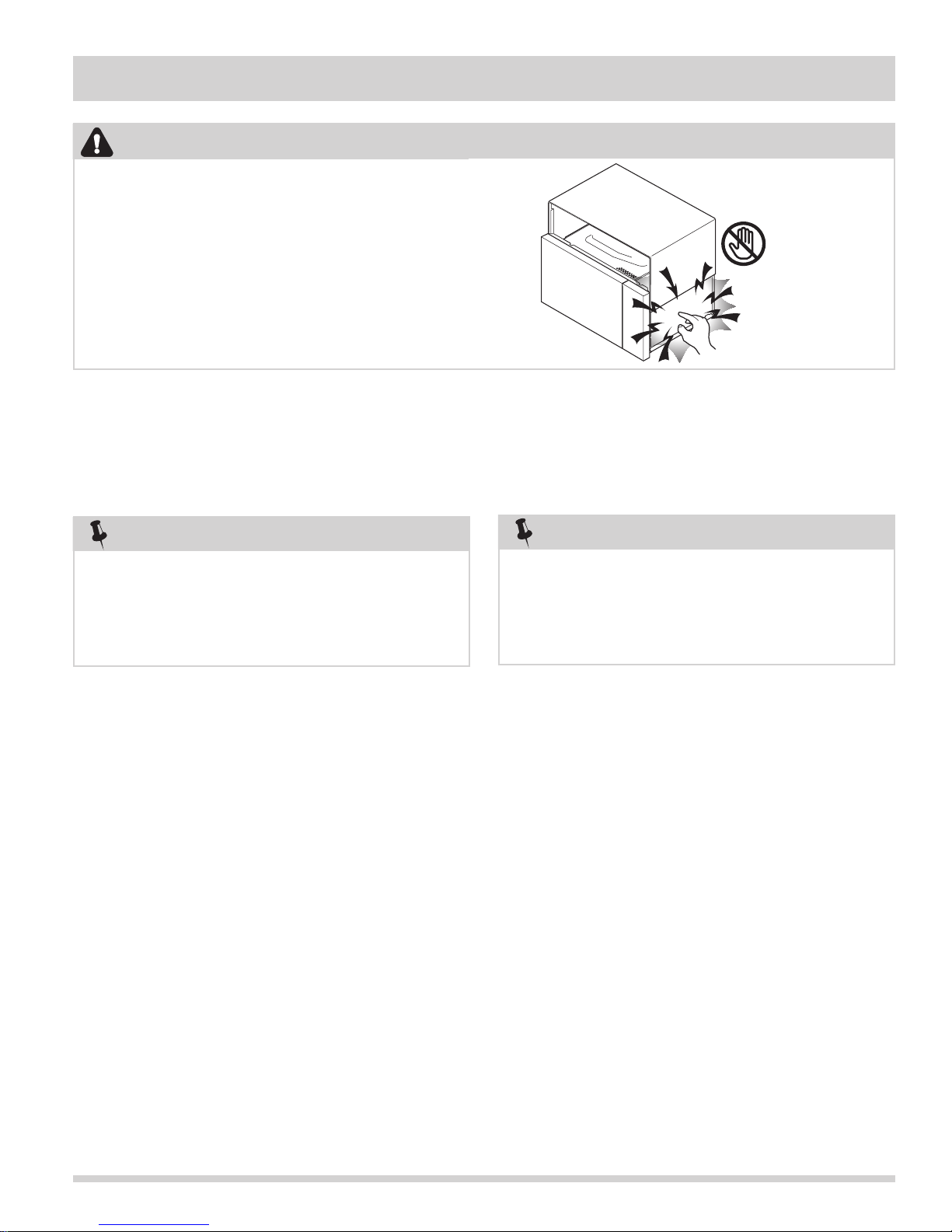
WARNING
Microwave ovens contain circuitry capable of producing
very high voltage and current. contact with THE
following parts may result in a severe, possibly fatal,
electrical shock.
Inverter unit, that includes High Voltage Capacitor,
High Voltage Power Transformer, High Voltage Rectifier,
Heat sink etc., and Magnetron, High Voltage Harness etc..
Read the Service Manual carefully and follow all
instructions.
Don't Touch !
Danger High
Voltage
Before Servicing
1. Disconnect the power supply cord, and then remove
outer case.
2. Open the door and block it open.
3. Discharge high voltage capacitor.
NOTE
To discharge the high voltage capacitor, wait for 60
seconds and then short-circuit the connection of the
high-voltage capacitor (that is the connecting lead of
the high-voltage rectifier) against the chassis with the
use of an insulated screwdriver.
Whenever troubleshooting is performed, the power
supply must be disconnected. It may, in some cases, be
necessary to connect the power supply after the outer
case has been removed, in this event:
1. Disconnect the oven power supply cord and then
remove the outer case.
2. Open the door and block it open.
3. Discharge high voltage capacitor.
4. Disconnect leads to the primary of the inverter unit.
5. Ensure that these leads remain isolated from other
components and oven chassis by using insulation
tape.
6. After that procedure, reconnect the power supply
cord.
When Testing Is Completed
1. Disconnect the power supply cord, and then remove
outer case.
2. Open the door and block it open.
3. Discharge high voltage capacitor.
NOTE
To discharge the high voltage capacitor, wait for 60
seconds and then short-circuit the connection of the
high-voltage capacitor (that is the connecting lead of
the high-voltage rectifier) against the chassis with the
use of an insulated screwdriver.
4. Reconnect leads to the primary of the inverter unit.
5. Reinstall the outer case (cabinet).
6. Reconnect the power supply cord after the outer
case is installed.
7. Run the oven and check all functions.
After repairing
1. Reconnect all leads removed from components
during testing.
2. Reinstall the outer case (cabinet).
3. Reconnect the power supply cord after the outer
case is installed.
4. Run the oven and check all functions. Microwave
ovens should not be run empty. To test for the
presence of microwave energy within a cavity,
place a cup of cold water on the oven turntable,
close the door and set the power to HIGH and then
set the microwave timer for two (2) minutes. When
the two minutes has elapsed (timer at zero) carefully check that the water is now hot. If the water
remains cold carry out Before Servicing procedure
and re-examine the connections to the component
being tested.
1-5

Section 1 Basic Information
Microwave Measurement Procedure (USA)
A. Requirements:
1) Microwave leakage limit (Power density limit): The power density of microwave radiation emitted by a
microwave oven should not exceed 1 mW/cm2 at any point 5 cm or more from the external surface of the
oven, measured prior to acquisition by a purchaser, and thereafter (through the useful life of the oven),
5 mW/cm2 at any point 5 cm or more from the external surface of the oven.
2) Safety interlock switches: Primary interlock switch shall prevent microwave radiation emission in excess of the
requirement as above mentioned, secondary interlock switch shall prevent microwave radiation emission in
excess of 5 mW/cm2 at any point 5 cm or more from the external surface of the oven.
B. Preparation for testing:
Before beginning the actual measurement of leakage, proceed as follows:
1) Make sure that the actual instrument is operating normally as specified in its instruction booklet.
Important:
Survey instruments that comply with the requirement for instrumentation as prescribed by the performance
standard for microwave ovens, 21 CFR 1030.10(c)(3)(i), must be used for testing.
2) Place the oven tray in the oven cavity.
3) Place the load of 275±15 ml (9.8 oz) of tap water initially at 20°±5°C (68°F) in the center of the oven cavity.
The water container shall be a low form of 600 ml (20 oz) beaker with an inside diameter of approx. 8.5 cm
(3-1/2 in.) and made of an electrically nonconductive material such as glass or plastic. The placing of this
standard load in the oven is important not only to protect the oven, but also to insure that any leakage is
measured accurately.
4) Set the cooking control on Full Power Cooking Mode.
5) Close the door and select a cook cycle of several minutes. If the water begins to boil before the survey is
completed, replace it with 275 ml of cool water.
C. Leakage test:
Closed-door leakage test (microwave measurement)
1) Grasp the probe of the survey instrument and hold it perpendicular to the gap between the door and
the body of the oven.
2) Move the probe slowly, not faster than 1 in./sec. (2.5 cm/sec.) along the gap, watching for the maximum
indication on the meter.
3) Check for leakage at the door screen, sheet metal seams and other accessible positions where the continuity
of the metal has been breached (eg., around the switches, indicator, and vents). While testing for leakage
around the door pull the door away from the front of the oven as far as is permitted by the closed latch
assembly.
4) Measure carefully at the point of highest leakage and make sure that the highest leakage is no greater than
4 mW/cm2, and that the primary interlock switch and secondary interlock switch do turn the oven OFF before
any door movement.
NOTE: After servicing, record data on service invoice and microwave leakage report.
1-6

Section 1 Basic Information
Microwave Measurement Procedure (Canada)
After adjustment of the door switches are completed individually or collectively, switch test and microwave leakage test
must be performed with survey instrument and test result must be confirmed to meet the requirement of the
performance standard for microwave ovens as under mentioned.
A. Requirements:
Every microwave oven shall function in such a manner that when the oven is fully assembled and operating with
its service controls and user controls adjusted to yield the maximum output, the leakage radiation, at all points at
least 5 cm. from the external surface of the oven, does not exceed:
1) 1.0 mW/cm2 with the test load of 275 ± 15 ml of water at an initial temperature 20 ±5°C.
2) 5.0 mW/cm2 when the outer enclosure is removed with a test load of 275 ± 15 ml of water at an initial
temperature 20±5°C.
3) 5.0 mW/cm2 without a test load.
B. Preparation for testing:
Before beginning the actual measurement of leakage, proceed as follows:
1) Make sure that the actual instrument is operating normally as specified in its instruction booklet.
Survey instruments that comply with the requirement for instrumentation as prescribed by CSA and NHW
performance standard for microwave ovens must be used for testing recommended instruments are, NARDA
8100 and NARDA 8200.
2) Place the oven tray in the oven cavity.
3) Place the load of 275±15 ml (9.8 oz) of tap water initially at 20°±5°C (68°F) in the center of oven cavity.
The water container shall be a low form of a 600 ml (20 oz) beaker with an inside diameter of approx. 8.5 cm
(3-1/2 in.) and made of an electrically nonconductive material such as glass or plastic. The placing of this
standard load in the oven is important not only to protect the oven, but also to insure that any leakage
is measured accurately.
4) Set the cooking control on Full Power Cooking Mode.
5) Close the door and select a cook cycle of several minutes. If the water begins to boil before the survey is
completed, replace it with 275 ml of cool water.
C. Leakage test with enclosure installed:
1) Grasp probe of survey instrument and hold it perpendicular to gap between door and the body of the oven.
2) Move the probe slowly, not faster than 2.5 cm/sec. along the gap, watching for maximum indication on meter.
3) Check for leakage at the door screen, sheet metal seams and other accessible positions where continuity
of the metal has been breached (eg., around the switches, indicator, and vents). While testing for leakage
around door, pull door away from the front of the oven as far as is permitted by the closed latch assembly.
4) Measure carefully at the point of highest leakage and make sure that the highest leakage is no greater
than 4 mW/cm2, and that the primary interlock switch and secondary interlock switch do turn the oven
OFF before any door movement.
D. Leakage test without enclosure:
1) Remove the enclosure (cabinet).
2) Grasp the probe of the survey instrument and hold it perpendicular to all mechanical and electric parts of the
oven that is accessible to the user of the oven including, but not limited to, the waveguide, cavity seams,
magnetron gap between the door and the body of the oven.
3) Move probe slowly, not faster than 2.5 cm/sec. along the gap, watching for the maximum indication on meter.
4) Measure carefully at the point of highest leakage and make sure that the highest leakage is under 5 mW/cm2.
CAUTION: Special attention should be given to avoid electrical shock because HIGH VOLTAGE is
generated during this test.
E. No Load test
1) Operate the oven without a load and measure the leakage by the same method as the above test procedure
“ Leakage test with enclosure installed”
2) Make sure that the highest leakage should not exceed 5 mW/cm2.
NOTE: After servicing, record data on service invoice and microwave leakage report.
1-7
Section 1 Basic Information
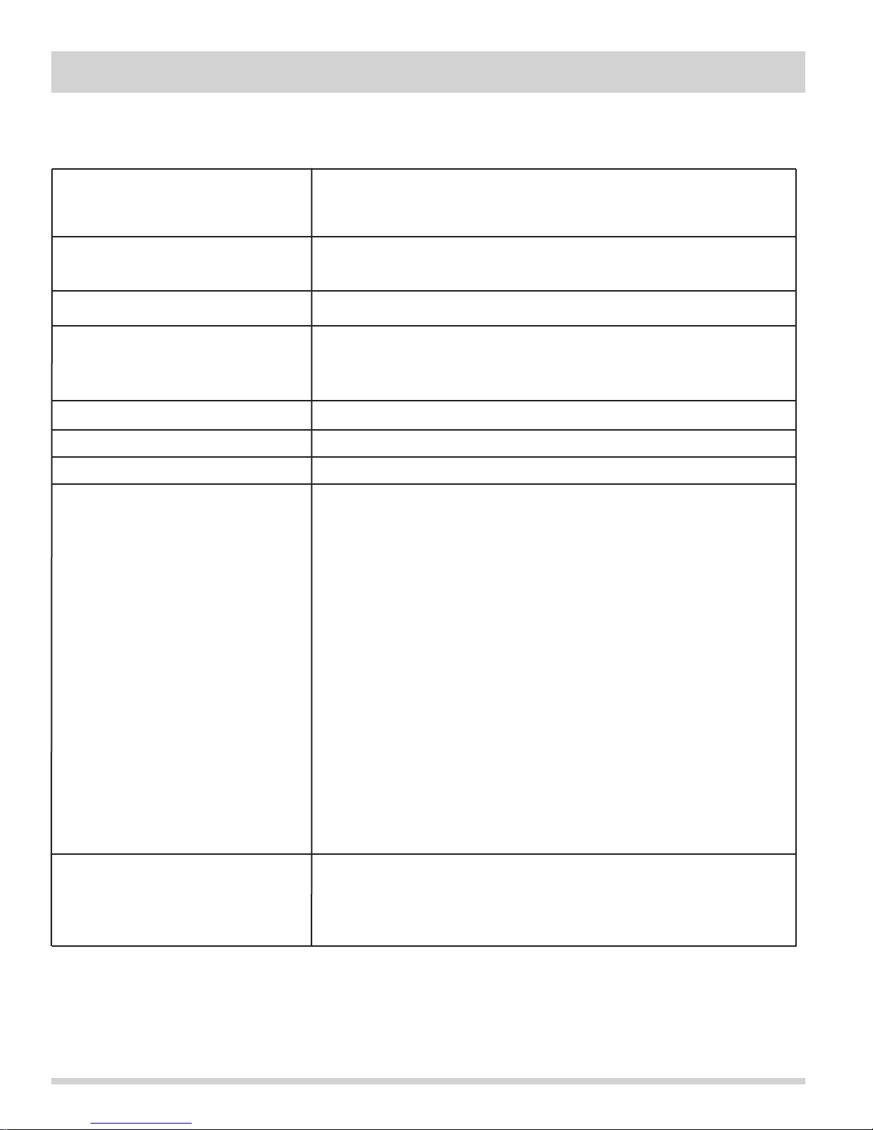
Product Specification
Item Description
Power Requirements (USA)120 Volts / 15 Amperes
60 Hertz
Single phase, 3 wire grounded
Power Output 1000 watts (IEC 705 Test Procedure)
Operating frequency of 2450MHz
Case Dimensions (excluding handle) Width 29-7/8” Height 16-13/32” Depth 15-1/32”
Cooking Cavity Dimensions Width 20-1/4”
(1.8 Cubic Feet ) Height 9-1/4”
Depth 14-13/32”
Hood Lamp 30 Watt x 2 incandescent light bulb
Weight Approx. 62.05 lbs.
Hood fan Approx. 300 C.F.M. High Mode
Control Complement Touch Control System
Clock ( 1:00 - 12:59 )
Timer (0 - 99 min. 99 seconds)
Microwave Power for Variable Cooking
Repetition Rate;
P-HI Full power throughout the cooking time
P-90 approx. 90% of Full Power
P-80 approx. 80% of Full Power
P-70 approx. 70% of Full Power
P-60 approx. 60% of Full Power
P-50 approx. 50% of Full Power
P-40 approx. 40% of Full Power
P-30 approx. 30% of Full Power
P-20 approx. 20% of Full Power
P-10 approx. 10% of Full Power
P-0 No power throughout the cooking time
Popcorn pad, Reheat pad, Cook pad, Defrost pad, Number selection pads
Power Level pad, Timer / Clock pad, Light button, Fan button, Clear/Off
button, START/ Plus 1-8 Min button,
Safety Standard UL Listed FCC Authorized
DHHS Rules, CFR, Title 21, Chapter 1, Subchapter J
Canadian Standards Association
Health CANADA, Industry Canada
1-8
Section 1 Basic Information
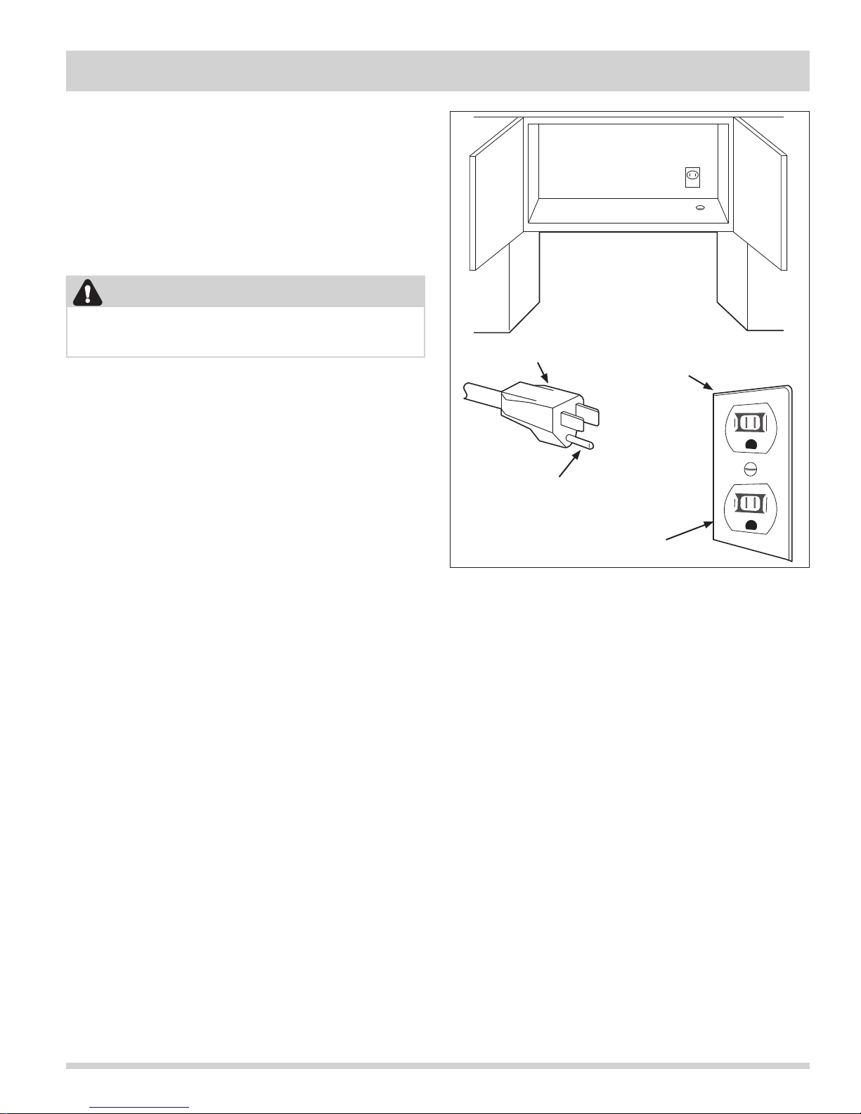
3-Pronged Plug
Grounded
Receptacle Box
Grounding Pin
3-Pronged Receptacle
Grounding Instructions
This oven is equipped with a three prong grounding
plug. It must be plugged into a wall receptacle that is
properly installed and grounded in accordance with the
National Electrical Code, local codes and ordinances.
In the event of an electrical short circuit, grounding
reduces the risk of electric shock by providing an escape
wire for the electric current.
WARNING
Improper use of the grounding plug can result in
a risk of electric shock.
Electrical Requirements
The oven is equipped with a 3-prong grounding plug.
DO NOT UNDER ANY CIRCUMSTANCES CUT OR
REMOVE THE GROUNDING PIN FROM THE PLUG.
The power supply cord and plug must be connected to a
separate 120 Volt AC, 60 Hz, 15 Amp. or more dedicated
line, using a grounded receptacle. When installing this
appliance, observe all applicable codes and ordinances.
A short power-supply cord is provided to reduce risks of
becoming entangled in or tripping over a longer cord.
Where a two-pronged wall-receptacle is encountered,
it is the personal responsibility and obligation of the
customer to contact a qualified electrician and have it
replaced with a properly grounded three-pronged wall
receptacle or have a grounding adapter properly
grounded and polarized.
If an extension cord must be used, it should be a 3-wire,
15 amp. or more cord. Do not drape over a countertop
or table where it can be pulled on by children or tripped
over accidentally.
1-9
Section 1 Basic Information
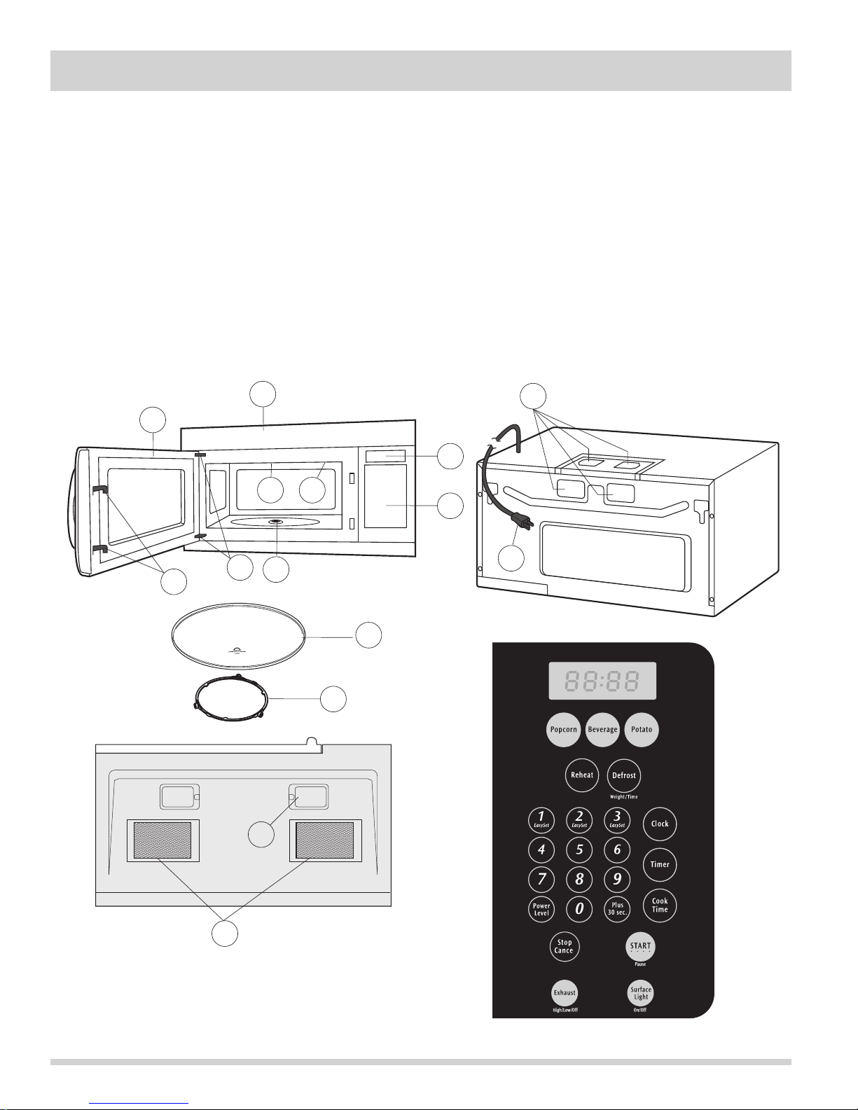
Oven Diagram
1. Oven door with see-through window.
2. Door hinges.
3. Waveguide cover.
4. Turntable motor shaft.
5. Oven lamp. It will light when oven is operating or
door is open.
6. Door latches. The oven will not operate unless the
door is securely closed.
7. Auto Touch control panel.
8. Time display: Digital display, 99 minutes 99 seconds.
9
1
3
5
2
4
6
9. Ventilation openings.
10. Light Cover.
11. Grease filters.
12. Removable turntable. The turntable will rotate
clockwise or counterclockwise. Only remove for
cleaning.
13. Removable turntable support.
14. Power supply cord
9
8
7
14
11
12
13
10
1-10

Section 2 Operation
Operating Sequence Description
The following is a description of component functions
during oven operation.
OFF CONDITION
Closing the door activates the door sensing switch and
secondary interlock switch. (In this condition, the
monitor switch contacts are opened.) When oven is
plugged in, 120 volts AC is supplied to the control unit.
(Figure 2-1).
1. The display will show “WELCOME, PRESS CLEAR
AND PRESS CLOCK”. To set any program or set the
clock, you must first touch the STOP/CLEAR button.
The display will clear, and “ : “ appears.
COOKING CONDITION
Program desired cooking time touching the NUMBER
pads. When the START pad is touched, the following
operations occur:
1. The contacts of relays are closed and components
connected to the relays are turned on as follows.
(For details, refer to Figure 2-2)
RELAY CONNECTED COMPONENTS
RY1 Oven Lamp / Fan motor
RY2 Power Transformer
RY3 Cooktop Lamp
RY6 Hood Fan Motor
6. When the door is opened during a cook cycle,
monitor switch, door sensing switch, primary
interlock switch, and secondary interlock relay are
activated with the following results. The circuits to
the stirrer motor, the cooling fan motor, the
turntable motor, and the high voltage components
are de-energized, and the digital read-out displays
the time still remaining in the cook cycle when the
door was opened.
7. The monitor switch is electrically monitoring the
operation of the primary interlock switch, and door
sensing switch is mechanically associated with
the door so that it will function in the following
sequence.
(1) When the door opens from a closed position,
the secondary interlock relay, door sensing
switch, and primary interlock switch open their
contacts, and then the monitor switch contacts
close.
(2) When the door is closed from the open position,
the monitor switch contacts open first. Then the
contacts of the primary interlock switch and
door sensing switch close. And contacts of the
relay (RY1) open.
If the primary interlock switch and secondary interlock
relay (RY2) fail with the contacts closed when the door
is opened, the closing of the monitor switch contacts will
form a short circuit through the monitor fuse, primary interlock switch, relay (RY1) and secondary interlock relay
(RY2), causing the monitor fuse to blow.
2. 120 volts AC is supplied to the primary winding of
the power transformer and is converted to about
3.3 volts AC output on the filament winding, and
approximately 2200 volts AC on the high voltage
winding.
3. The filament winding voltage heats the magnetron
filament and the H.V. winding voltage is sent to a
voltage doubler circuit.
4. The microwave energy produced by the magnetron
is channeled through the waveguide into the cavity
feedbox, and then into the cavity where the food
is placed to be cooked.
5. Upon completion of the cooking time, the power
transformer, oven lamp, etc. are turned off, and the
generation of microwave energy is stopped. The
oven will revert to the OFF condition.
2-1
Section 2 Operation
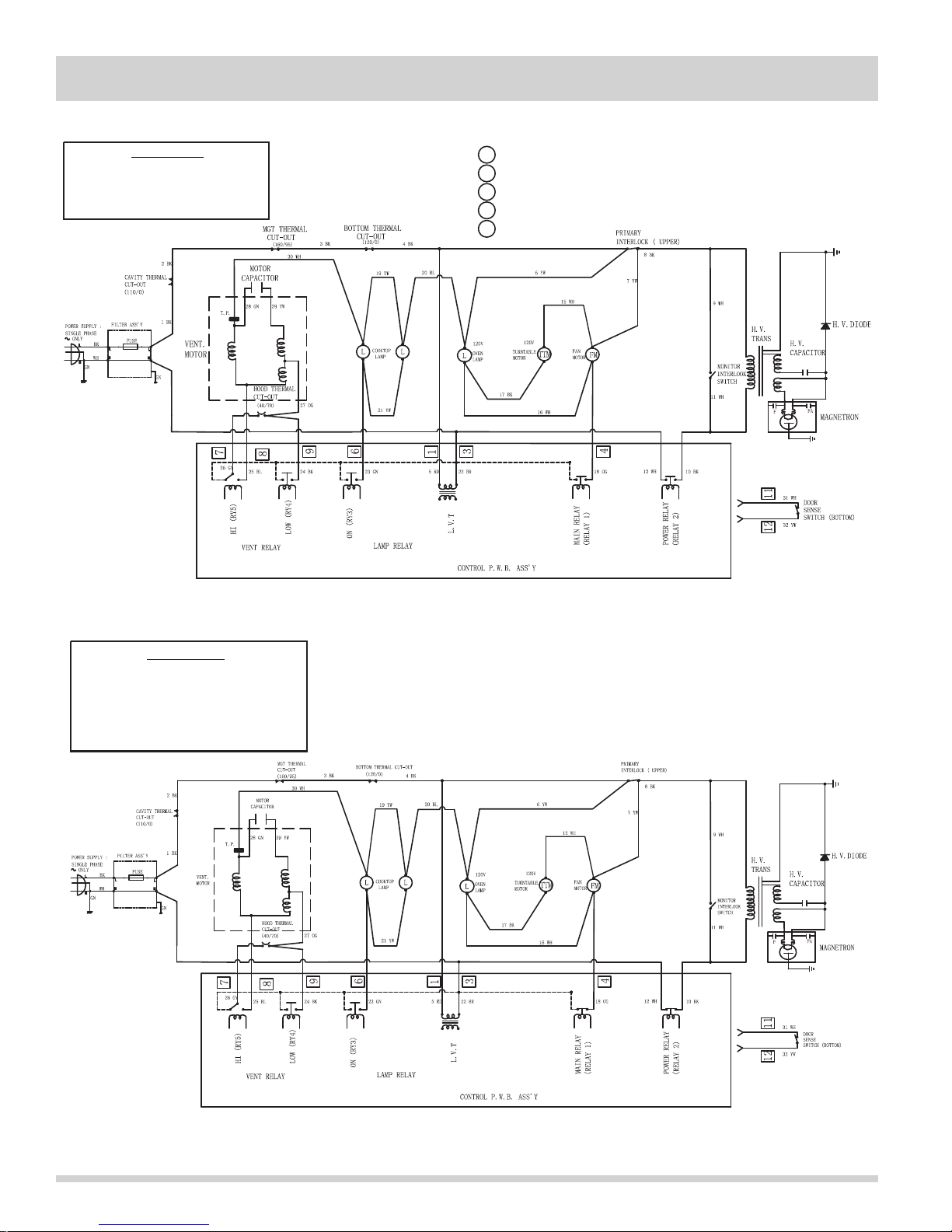
SCHEMATIC
NOTE: CONDITION OF OVEN
1. DOOR CLOSED.
2. CLOCK APPEARS ON DISPLAY.
OG : Orange
YW : Yellow
RD : Red
BL : Blue
: Green
GN
Figure 2-1. Oven Off Condition
BR
: Brown
WH : White
BK : Black
: Grey
GY
: Pink
PK
OL
- Oven Lamp
FM
- Fan Motor
TTM
- Turntable Motor
SM
- Stirrer Motor
CL
- Cooktop Lamp
SCHEMATIC
NOTE: CONDITION OF OVEN
1. DOOR CLOSED.
2. COOKING TIME PROGRAMMED.
3. VARIABLE COOKING CONTROL
"HIGH".
OG : Orange
YW : Yellow
RD : Red
BL : Blue
GN
: Green
: Brown
BR
WH : White
BK : Black
GY
: Grey
PK
: Pink
Figure 2-2. Oven ON (Cooking) Condition
2-2
Section 2 Operation
To Duct
To Duct
Grease
Filter
Hood
Intake
Duct R
Hood Fan
Motor
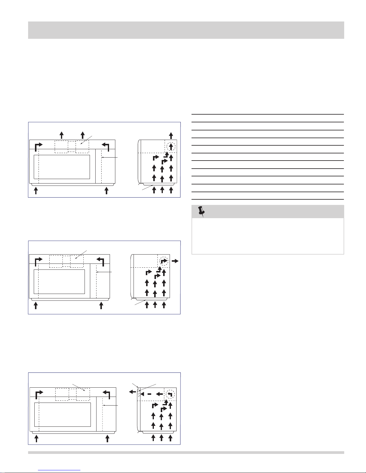
VENTILATION METHODS HOT AIR EXHAUST
1. Vertical Venting
For this venting method, hot air rising from the
conventional range below is drawn in by the hood fan
motor through the grease fi lters at the right and left
sides of the base cover, up through the right and left
sides of the oven cavity, then discharged vertically at rear
center top of the oven, into the customer’s vent system.
2. Horizontal Venting
The air handing is the same as Vertical Venting except
that fi nal air discharge is directed horizontally out from
the top rear of oven into the customer’s vent system.
Hood Fan
Motor
To Duct
POWER LEVEL P-0 TO P-90 COOKING
When Variable Cooking Power is programmed, the
120 volts A.C. is supplied to the power transformer
intermittently through the contacts of relay (RY2) which
is operated by the control unit within an interval second
time base. Microwave power operation is as follows:
Vari-Mode ON TIME OFF TIME
Power 10 (High) (100% Power) 29 sec. 0 sec.
Power 9 (P-90) (Approx. 90%) 26 sec. 3 sec.
Power 8 (P-80) (Approx. 80%) 23 sec. 6 sec.
Power 7 (P-70) (Approx. 70%) 20 sec. 9 sec.
Power 6 (P-60) (Approx. 60%) 17 sec. 12 sec.
Power 5 (P-50) (Approx. 50%) 14 sec. 15 sec.
Power 4 (P-40) (Approx. 40%) 11 sec. 18 sec.
Power 3 (P-30) (Approx. 30%) 8 sec. 21 sec.
Power 2 (P-20) (Approx. 20%) 5 sec. 24 sec.
Power 1 (P-10) (Approx. 10%) 3 sec. 26 sec.
Power 0 (P-0) (0% power) 0 sec. 29 sec.
NOTE
The ON/OFF time ratio does not correspond with
the percentage of microwave power, because
approximately 2 seconds are needed for heating of
the magnetron filament.
Hood
Intake
Duct R
Grease
Filter
3. Re-circulation (Inside venting)
The air handing is the same as VERTICAL VENTING
except that the final air discharge is directed horizontally
through the upper front of the oven into the kitchen. In
this case, the accessory charcoal Filter RK-240 must be
provided to filter the air before it leaves the oven.
Hood Fan
Motor
Hood Exhaust
Louver
Hood
Intake
Duct R
Charcoal
Filter
2-3

Section 2 Operation
Touch Control Panel Assembly Outline
The touch control section consists of the following units.
(1) Key unit
(2) Control Unit: The Control unit consists of LSI Unit and
Power Unit.
The principal functions of these units and the signals
communicated among them are explained below.
KEY UNIT
The key unit is composed of a matrix, signals generated
in the LSI are sent to the key unit through P20, P21, P22,
P25, and P26. When a key pad is touched, a signal is
completed through the key unit and passed back to the
LSI through P43, P44, P45 and P46 to perform the
function that was requested.
CONTROL UNIT
Control unit consists of LSI, power source circuit,
synchronizing signal circuit, reset circuit, buzzer circuit,
relay circuit indicator circuit and back light circuit.
1. (LSI)
This LSI controls the key strobe signal, relay driving
signal for oven function and indicator signal.
2. Power Source Circuit
This circuit generates voltages necessary for the
control unit from the AC line voltage. In addition,
the synchronizing signal is available in order to
compose a basic standard time in the clock circuit.
Symbol Voltage Application
VC -5.3V LSI(IC1)
7. Relay Circuit
To drive the magnetron, fan motor, turntable motor,
hood motor, and light the oven lamp and hood lamp.
8. Indicator Circuit
This circuit consists of 22 segments and 3 common
electrodes using a Light Crystal Display.
9. Back Light Circuit
A circuit to drive the back light (Light emitting diodes
LD1-LD4).
Component Descriptions
DOOR OPEN MECHANISM
The door is opened by pulling the door handle, refer to
the Figure 2-3.
Latch Heads
Latch Hook
Primary Interlock
Door
Door Sensing Switch
Figure 2-3. Door Open Mechanism
Switch
Monitor Switch
3. Synchronizing Signal Circuit
The power source synchronizing signal is available in
order to compose a basic standard time in the clock
circuit. It incorporates a very small error because it
works on commercial frequency.
4. Reset Circuit
This circuit generates a signal which resets the LSI
(IC1) to the initial state when power is supplied.
5. Buzzer Circuit
The buzzer is responds to signals from the LSI to
emit audible sounds (key touch sound and
completion sound).
6. Door Sensing Switch
A switch to inform the LSI if the door is open or
closed.
2-4
DOOR SENSING AND PRIMARY INTERLOCK
SWITCH
The primary interlock switch is mounted in the upper
position of the latch hook, and the door sensing switch in
the primary interlock system is mounted in the lower
position of the latch hook. The switches are activated by
the latch heads on the door. When the door is opened,
the switches interrupt the circuit to all components.
A cook cycle cannot take place until the door is firmly
closed, thereby activating both interlock switches. The
primary interlock system consists of the door sensing
switch and secondary interlock relay located on the
control circuit board.
 Loading...