

Frigidaire EI30SM35QSA, CFMV152CLBA, CFMV152CLWA, CFMV152KBA, CFMV152KMA Installation Guide
...Page 1
Installation
Overthe Range
Instructions
Questions? Carl 1-800-944-9044(us)
I
BEFORE YOU BEGIN
Read these instructions completely and carefully.
• IMPORTANT - Savethese
instructions for local inspector's use.
• IMPORTANT - Observoall
governing codes and ordinances.
• Note to Installer - Be sure to leave these
instructions with the Consumer.
1-800-265-8352(Canada)
Microwave Oven
or Visit our Website at: http://www.frigidaire.com
• Note to Consumer - Keep these
instructions for future reference.
• Skill level - Installation of this appliance requires
basic mechanical and electrical skills.
• Proper installation is the responsibility of the installer.
• Product failure due to improper installation is not
covered under the Warranty.
I
/
/
READ CAREFU LLY.
KEEP THESE INSTRUCTIONS.
pin 316495063
March 2010
Page 2
Installation Instructions
CONTENTS
General information
Important Safety Instructions .................................. 3
Electrical Requirements .......................................... 3
Damage - Shipment/Installation .............................. 4
Parts Included .......................................................... 4
Tools You Will Need ................................................ 5
Mounting Space ...................................................... 5
Step-by-step installation guide
Placement of The Mounting Plate ...................... 6-8
Removing the Mounting Plate ...................... 6
Finding the Wall Studs .................................. 6
Determining Wall Plate Location .................. 7
Aligning the Wall Plate ................................ 8
Adapting Microwave Blower
for Outside Back Exhaust ................ 17-18
Mount the Microwave Oven ................ 19
[] Recirculating ........................................
Attach Mounting Plate to Wall ............ 20
Preparation of Top Cabinet ................ 20
Check Blower Plate ............................ 21
Mount the Microwave Oven .......... 21-22
Installing or Change the
Charcoal Filter .................................... 22
Before You Use Your Microwave .......................... 23
20 _ 2 2
Installation Types ............................................... 9-22
Hood Exhaust .................................................. 10-11
_ Outside Top ............................
Attach Mounting Plate to Wall ............ 12
Preparation of Top Cabinet ................ 13
Adapting Microwave Blower for
Outside top Exhaust .................. 13-14
Checking for Proper Damper
Operation ............................................ 14
Mount the Microwave Oven .......... 14-15
Adjust the Exhaust Adaptor ................ 15
Connecting Ductwork .......................... 15
]Outside Back Exhaust 16-19
Preparing Rear Wall for
Outside Back Exhaust .......................... 16
Remove Blower Plate .............................. 16
Attach Mounting Plate to Wall ............ 17
Exhaust 12-15
Preparation of Top Cabinet ................ 17
2
Page 3
Installation Instructions
IMPORTANT SAFETY INSTRUCTIONS
This product requires a three-prong grounded outlet.
The installer" must perform a ground continuity check
on the power" outlet box before beginning the
installation to insure that the outlet box is properly
grounded. If not properly grounded, or" if the outlet
box does not meet electrical requirements noted
(under ELECTRICAL REQUIREMENTS), a qualified
electrician should be employed to correct any
deficiencies.
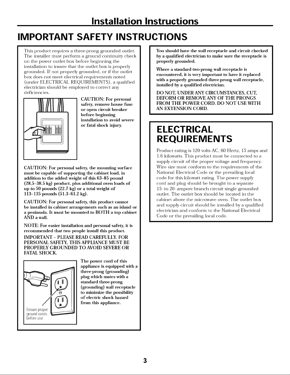
CAUTION: For personal
safety, remove house fuse
or open circuit breaker
before beginning
installation to avoid severe
or fatal shock injury.
CAUTION: For personal safety, the mounting surface
must be capable of supporting the cabinet load, in
addition to the added weight of this 63-85 pound
(28.5-38.5 kg) product, plus additional oven loads of
up to 50 pounds (22.7 kg) or a total weight of
113-135 pounds (51.3-61.2 kg).
CAUTION: For personal safety, this product cannot
be installed in cabinet arrangements such as an island or
a peninsula. It must be mounted to BOTH a top cabinet
AND a wall.
You should have the wall receptacle and circuit checked
by a qualified electrician to make sure the receptacle is
properly grounded.
Where a standard two-prong wall receptacle is
encountered, it is very important to have it replaced
with a properly grounded three-prong wall receptacle,
installed by a qualified electrician.
DO NOT, UNDER ANY CIRCUMSTANCES, CUT,
DEFORM OR REMOVE ANY OF THE PRONGS
FROM THE POWER CORD. DO NOT USE WITH
AN EXTENSION CORD.
ELECTRICAL
REQUIREMENTS
Product rating is 120 volts AC, 60 Hertz, 15 amps and
1.6 kilowatts. This product must be connected to a
supply circuit of the proper voltage and frequency.
Wire size must conform to the requirements of the
National Electrical Code or the prevailing local
code for this kilowatt rating. The power supply
cord and plug should be brought to a separate
15- to 20- ampere branch circuit single grounded
outlet. The outlet box should be located in the
cabinet above the microwave oven. The outlet box
and supply circtfit should be installed by a qualified
electrician and conform to the National Electrical
Code or the prevailing local code.
NOTE: For easier installation and personal safety, it is
recommended that two people install this product.
IMPORTANT - PLEASE READ CAREFULLY. FOR
PERSONAL SAFETY, THIS APPLIANCE MUST BE
PROPERLY GROUNDED TO AVOID SEVERE OR
FATAL SHOCK.
The power cord of this
appliance is equipped with a
three-prong (grounding)
plug which mates with a
standard three-prong
(grounding) wall receptacle
to minimize the possibility
of electric shock hazard
from this appliance.
Ensureproper
groundexists
beforeuse
3
Page 4
Installation Instructions
DAMAGE--SHIPMENT/
INSTALLATION
• If the unit is damaged in shipment, return the
unit to the store in which it was bought for repair
or replacement.
• If the unit is damaged by the customer, repair or
replacement is the responsibility of the customer.
• If the unit is damaged by the installer (if other
than the customer), repair or replacement must
be made by arrangement between customer
and installer
PARTS INCLUDED
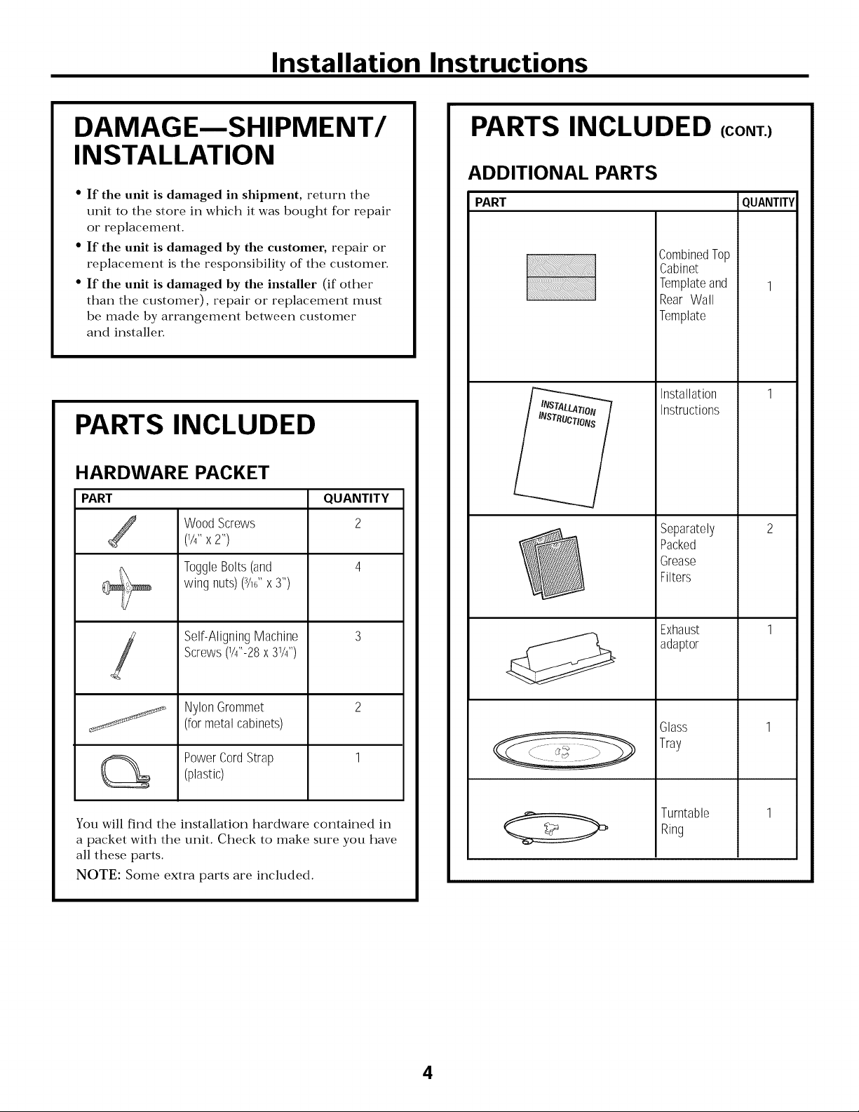
HARDWARE PACKET
PART
Wood Screws
/
(1/4" X 2")
ToggleBolts(and
wingnuts)(3/16"x3")
QUANTITY
2
+
PARTS INCLUDED (CONT.)
ADDITIONAL PARTS
PART QUANTITY
i_!i_i!_!iiii_ii!i!i!ii!i_i!_ii!i!iii_iiii_i!i!i!i!i!_!__ii_i!___i!_i!!i!_!!!!!iiiiiiiii!!!ii!!!i_i_!_!i!i_i_i!i_i!ii!i!iii!iiiii!i!!i!!i!!i!i!i!iiiiiii!ii!i!i!iiii!iii_i'
i
CombinedTop
Cabinet
Templateand
Rear Wall
Template
Installation
Instructions
Separately
Packed
Grease
Filters
Sel?AligningMachine
Screws(1/4"-28x 31/4'')
!
NylonGrommet
(formetalcabinets)
PowerCordStrap
(plastic)
You will find the installation hardware contained in
a packet with the unit. Check to make sure you have
all these parts.
NOTE: Some extra parts are included.
Exhaust
adaptor
Glass
Tray
Turntable
Ring
4
Page 5
Installation Instructions
TOOLS YOU WILL NEED
# 1Phillipsscrewdriver
Tinsnips(forcutting
damper,if required)
Gloves
Scissors
(tocuttemplate,if necessary)
Pencil
din===--
Ruleror tapemeasureand
t edge
Electricdrill with 3/16",1/2"and%"
drill bits
0
Carpentersquare
(optional)
Fillerblocksor scrap
woodpieces,if needed
fortop cabinetspacing
(usedonrecessedbottom
cabinetinstallationsonly)
Saw(saber,holeor keyhole)
Safetygoggles
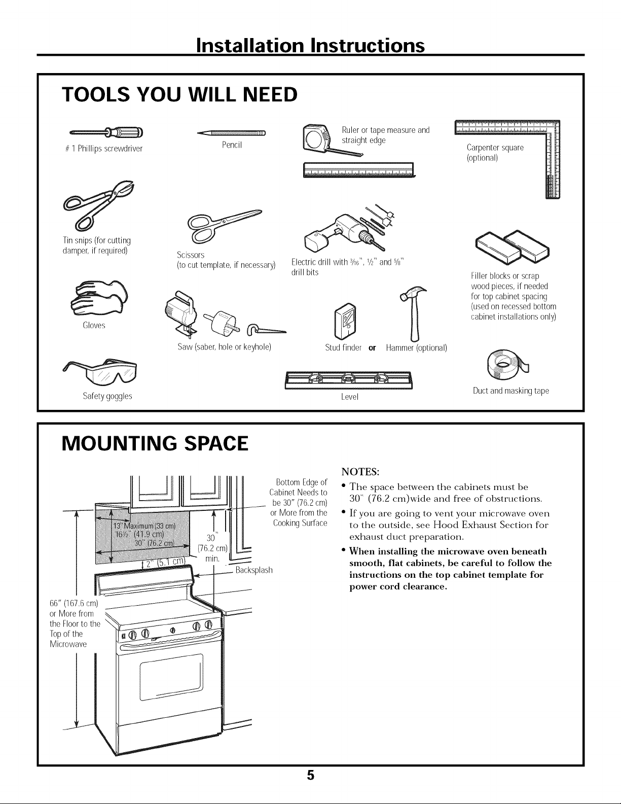
MOUNTING SPACE
--3
66" (167,6cm)
or Morefrom
the Floorto the
Topof the
Microwave
Backsplash
BottomEdgeof
CabinetNeedsto
be30" (76,2cm)
or Morefrom the
CookingSurface
Studfinder or
Level
NOTES:
• The space between the cabinets must be
30" (76.2 cm)wide and free of obstructions.
• If you are going to vent your microwave oven
to the outside, see Hood Exhaust Section for
exhaust duct preparation.
• When installing the microwave oven beneath
smooth, flat cabinets, be careful to follow the
instructions on the top cabinet template for
power cord clearance.
Hammer(optional)
Ductandmaskingtape
5
Page 6
Installation Instructions
PLACEMENT OF THE MOUNTING PLATE
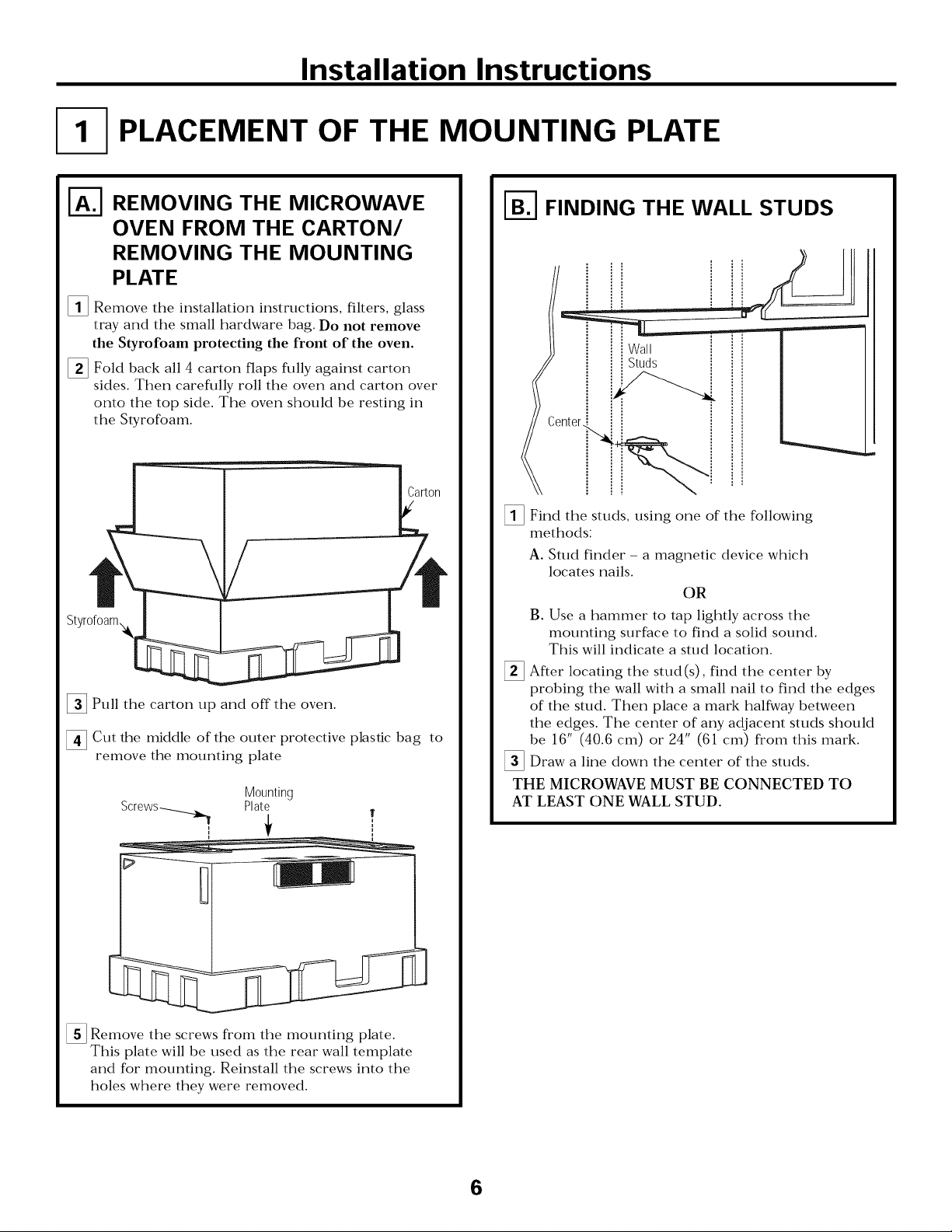
I-_ REMOVING THE MICROWAVE
OVEN FROM THE CARTON/
REMOVING THE MOUNTING
PLATE
[]Remove the installation instructions, filters, glass
tray and the small hardware bag. Do not remove
the Styrofoam protecting the front of the oven.
[] Fold back all 4 carton flaps fully against carton
sides. Then carefully roll the oven and carton over
onto the top side The oven should be resting in
the Styrofoam.
Styrofoam_
[]Pull the carton up and off the oven
Cut the middle of the outer protective plastic bag to
remove the mounting plate
Screws-_ Plate
Mounting
f
i
u
I-_ FINDING THE WALL STUDS
i waRm
i Studs
[]Find the studs, using one of the following
methods:
A. Stud finder - a magnetic device which
locates nails.
OR
B. Use a hammer to tap lightly across the
mounting surface to find a solid sound.
This will indicate a stud location
[] After locating the stud(s), find the center by
probing the wall with a small nail to find the edges
of the stud. Then place a mark halfway between
the edges. The center of any adjacent studs should
be 16" (40.6 cm) or 24" (61 cm) from this mark.
[]Draw a line down the center of the studs.
THE MICROWAVE MUST BE CONNECTED TO
AT LEAST ONE WALL STUD.
[]Remove the screws from the mounting plate.
This plate will be used as the rear wall template
and for mounting. Reinstall the screws into the
holes where they were removed.
6
Page 7
Installation Instructions
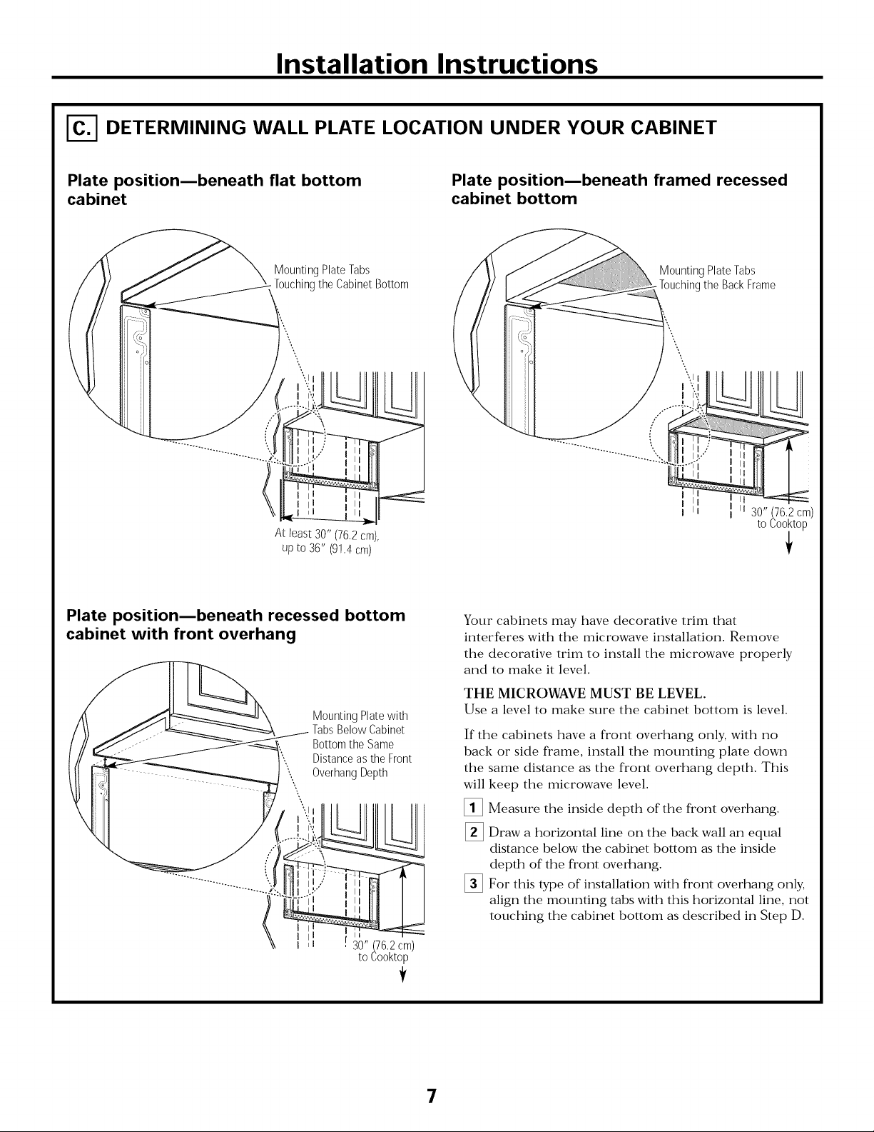
DETERMINING WALL PLATE LOCATION UNDER YOUR CABINET
Plate positionmbeneath flat bottom
cabinet
MountingPlateTabs
Touchingthe CabinetBottom
At least30" (76.2cm),
upto 36" (9!.4 cm)
Plate positionmbeneath framed recessed
cabinet bottom
MountingPlateTabs
.Touchingthe BackFrame
I
I ii 30" (76,2 cm)
to Cooktop
i
Plate position_beneath recessed bottom
cabinet with front overhang
Mounting Plate with
Tabs Below Cabinet
Bottom the Same
Distance as the Front
Overhang Depth
30" (76,2 cm)
to Cooktop
Your cabinets may have decorative trim that
interferes with the microwave installation. Remove
the decorative trim to install the microwave properly
and to make it level.
THE MICROWAVE MUST BE LEVEL.
Use a level to make sure the cabinet bottom is level.
If the cabinets have a front overhang only, with no
back or side frame, install the mounting plate down
the same distance as the front overhang depth. This
will
keep the microwave level.
[]
Measure the inside depth of the front overhang.
%
Draw a horizontal line on the back wall an equal
distance below the cabinet bottom as the inside
depth of the front overhang.
%
For this type of installation with front overhang only,
align the mounting tabs with this horizontal line, not
touching the cabinet bottom as described in Step D.
!
7
Page 8
Installation Instructions
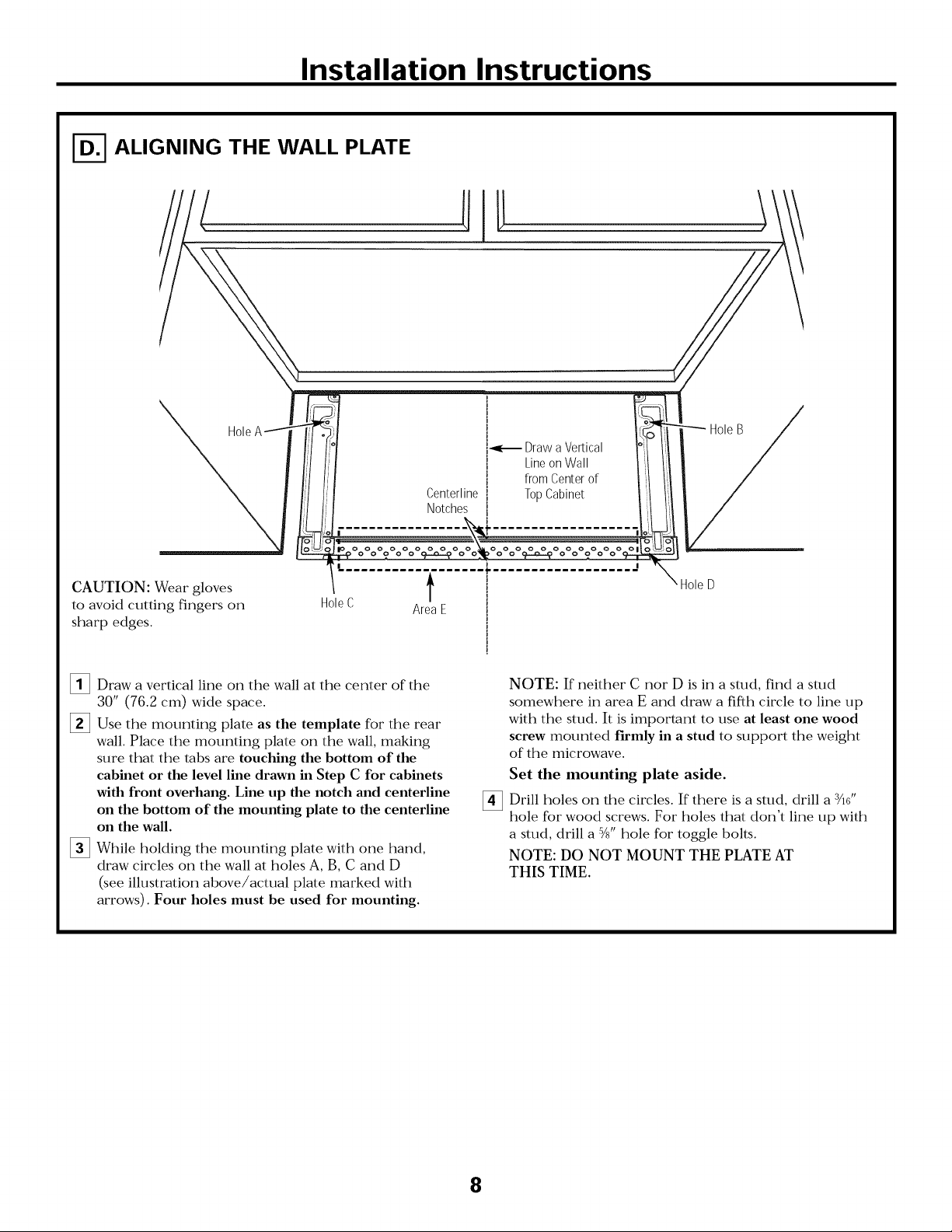
ALIGNING THE WALL PLATE
j_,,_ Draw a Vertical
i Line on Wall _I
I from Center of ,:1
Centerline i Top Cabinet t!t
Notches i I_I
I
-_? o o ? o o cF--o---_o c _ o o Or---o-_o o o_
CAUTION: Wear gloves
to avoid cutting fingers on
sharp edges.
[]Draw a vertical line on the wall at the center of the
30" (76.2 cm) wide space.
[]Use the mounting plate as the template for the rear
wall. Place the mounting plate on the wall, making
sure that the tabs are touching the bottom of the
cabinet or the level line drawn in Step C for cabinets
with front overhang. Line up the notch and centerline
on the bottom of the mounting plate to the centerline
on the wall.
[]While holding the mounting plate with one hand,
draw circles on the wall at holes A, B, C and D
(see illustration above/actual plate marked with
arrows). Four holes must be used for mounting.
Hole C Area E
I ,
\ Hole D
I
I
NOTE: If neither C nor D is in a stud, find a stud
somewhere in area E and draw a fifth circle to line up
with the stud. It is important to use at least one wood
screw mounted firmly in a stud to support the weight
of the microwave.
Set the mounting plate aside.
Drill holes on the circles. If there is a stud, drill a sad'
hole for wood screws. For holes that don't line up with
a stud, drill a 5/_,,hole for toggle bolts.
NOTE: DO NOT MOUNT THE PLATE AT
THIS TIME.
8
Page 9
Installation Instructions
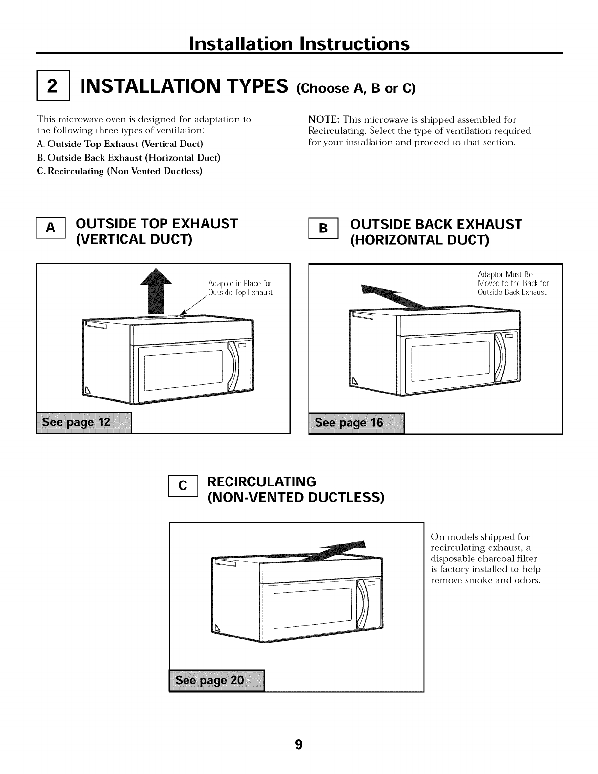
INSTALLATION TYPES
This microwave oven is designed for adaptation to
the following three types of ventilation:
A. Outside Top Exhaust (Vertical Duct)
B. Outside Back Exhaust (Horizontal Duct)
C. Recirculating (Non-Vented Ductless)
-_ OUTSIDE TOP EXHAUST
(VERTICAL DUCT)
Adaptorin Placefor
OutsideTopExhaust
(Choose A, B or C)
NOTE: This microwave is shipped assembled for
Recirculating. Select the type of ventilation required
for your installation and proceed to that section.
OUTSIDE BACK EXHAUST
(HORIZONTAL DUCT)
AdaptorMust Be
Movedto theBackfor
OutsideBackExhaust
[_ RECIRCULATING
(NON-VENTED DUCTLESS)
9
On models shipped for
recirculating exhaust, a
disposable charcoal filter
is factory installed to help
remove smoke and odors.
Page 10
Installation Instructions
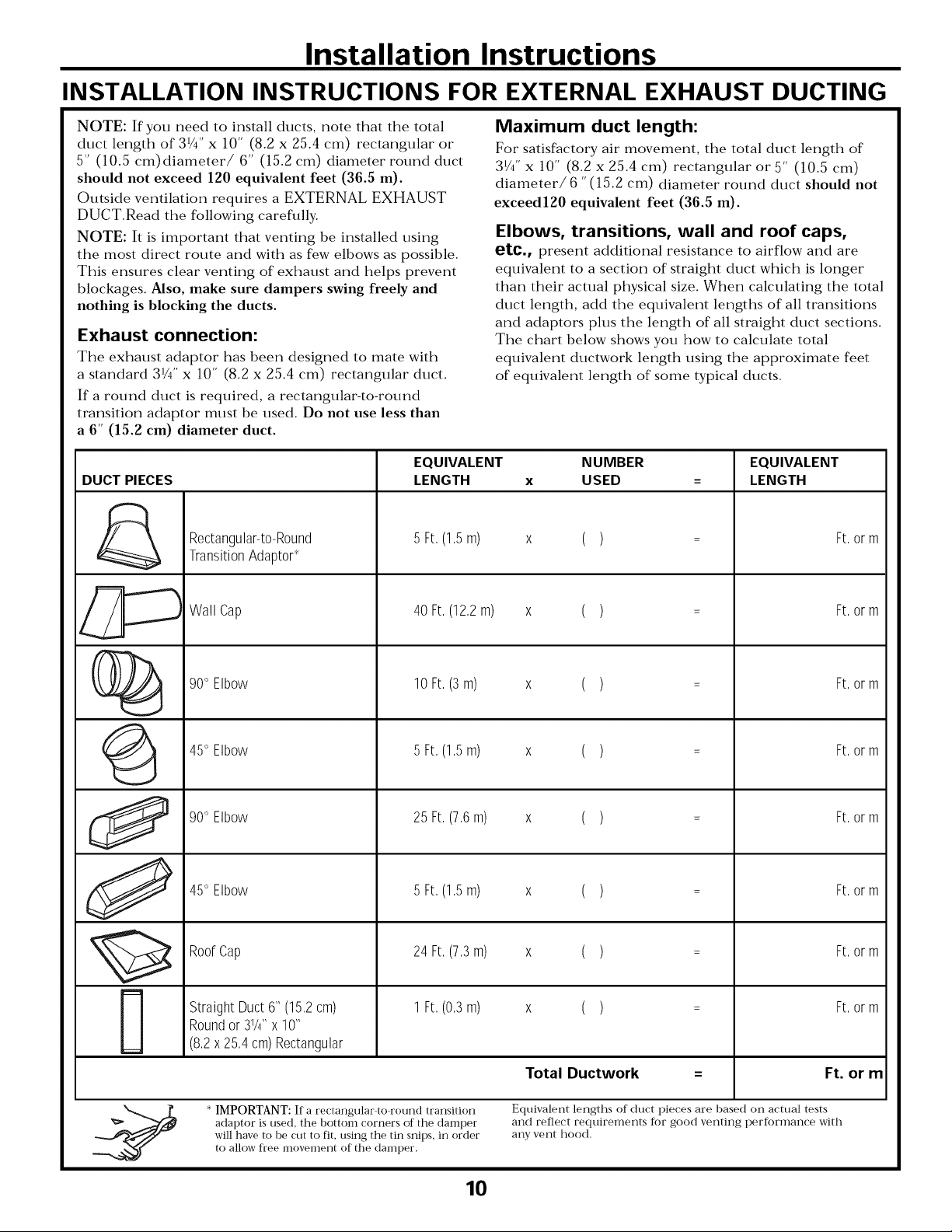
INSTALLATION INSTRUCTIONS FOR EXTERNAL EXHAUST DUCTING
NOTE: If you need to install ducts, note that the total
duct length of 31/4" x 10" (8.2 x 25.4 cm) rectangular or
5" (10.5 cm) diameter/ 6" (15.2 cm) diameter round duct
should not exceed 120 equivalent feet (36.5 m).
Outside ventilation requires a EXTERNAL EXHAUST
DUCT.Read the following carefully.
NOTE: It is important that venting be installed using
the most direct route and with as few elbows as possible.
This ensures clear venting of exhaust and helps prevent
blockages. Also, make sure dampers swing freely and
nothing is blocking the ducts.
Exhaust connection:
The exhaust adaptor has been designed to mate with
a standard 31/4'' x 10" (8.2 x 25.4 cm) rectangular duct.
If a round duct is required, a rectangular-to-round
transition adaptor must be used. Do not use less than
a 6" (15.2 cm) diameter duct.
EQUIVALENT
DUCT PIECES
&
Rectangular-to-Round
TransitionAdaptor*
LENGTH
5 Ft,(1,5m)
Maximum duct length:
For satisfactory air movement, the total duct length of
31/4'' x 10" (8.2 x 25.4 cm) rectangular or 5" (10.5 cm)
diameter/6 "(15.2 cm) diameter round duct should not
exceedl20 equivalent feet (36.5 m).
Elbows, transitions, wall and roof caps,
etc., present additional resistance to airflow and are
equivalent to a section of straight duct which is longer
than their actual physical size. When calculating the total
duct length, add the equivalent lengths of all transitions
and adaptors phrs the length of all straight duct sections.
The chart below shows you how to calculate total
equivalent ductwork length using the approximate feet
of equivalent length of some typical ducts.
NUMBER
x USED
x ()
EQUIVALENT
LENGTH
Ft,orm
J
@
0
J
Wall Cap
90° Elbow
45° Elbow
90° Elbow
45° Elbow
RoofCap
StraightDuct6" (15,2cm)
Roundor31/4``x 10"
(8,2x 25,4cm)Rectangular
40Ft,(12,2m)
10Ft,(3m)
5 Ft,(1,5m)
25Ft,(7,6m)
5 Ft,(1,5m)
24Ft,(7,3m)
1 Ft,(0,3m)
x ()
x ()
x ()
x ()
x ()
x ()
x ()
Ft,orm
Ft,orm
Ft,orm
Ft,orm
Ft,orm
Ft,orm
Ft,orm
* IMPORTANT: If a rectangular to round transition
adaptor is used, the bottom corners of the damper
will have to be cut to fit, using the tin snips, in order
to allow free movement of the damper.
10
Total Ductwork
Equivalent lengths of duct pieces are based on actual tests
and reflect requirements ti)r good venting pertbrmance with
any vent hood.
Ft. or m
Page 11
Installation Instructions
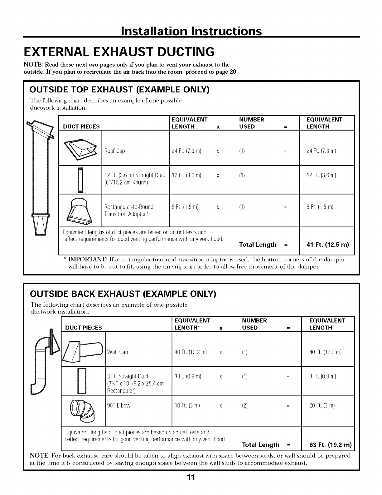
EXTERNAL EXHAUST DUCTING
NOTE: Read these next two pages only if you plan to vent your exhaust to the
outside. If you plan to recirculate the air back into the room, proceed to page 20.
OUTSIDE TOP EXHAUST (EXAMPLE ONLY)
The following chart describes an example of one possible
ductwork installation.
EQUIVALENT NUMBER EQUIVALENT
DUCT PIECES
LENGTH x USED = LENGTH
Roof Cap
12Ft,(3,6m)StraightDuct 12 Ft,(3,6m) x (1) = 12 Ft,(3,6m)
(6'715,2cmRound)
Rectangular-to-Round 5 Ft,(1,5m) x (1) = 5 Ft,(1,5m)
TransitionAdaptor*
Equivalentlengthsofductpiecesarebasedonactualtestsand
reflectrequirementsfor goodventingperformancewith anyvent hood,
* IMPORTANT: If a rectangular-to-round transition adaptor is used, the bottom corners of the damper
will have to be cut to fit, using the tin snips, ira order to allow fi'ee movement of the damper:
24Ft,(7,3m) x (1) 24Ft, (7,3m)
OUTSIDE BACK EXHAUST (EXAMPLE ONLY)
The following chart describes an example of one possible
ductwork installation.
EQUIVALENT NUMBER EQUIVALENT
LENGTH* USED = LENGTHDUCT PIECES x
Total Length = 41 Ft. (12.5 m)
":_::[_ Cap (12,2m) x
(_ 90° Elbow 10Ft,(3 m) x
Equivalentlengthsof ductpiecesarebasedonactualtests and
reflectrequirementsfor goodventingperformancewith anyventhood,
NOTE: For- back exhaust, care should be taken to align exhaust with space between studs, or"wall should be prepared
at the time it is constructed by leaving enough space between the wall studs to accommodate exhaust.
Wall 40Ft,
3Ft,StraightDuct 3Ft, (0,9m) x
(31/g'x 10'78,2x 25,4cm
Rectangular)
(1) 40Ft,(12,2m)
(1) = 3Ft,(0,9m)
(2) = 20Ft,(3 m)
Total Length = 63 Ft. (19.2 m)
11
Page 12
Installation Instructions
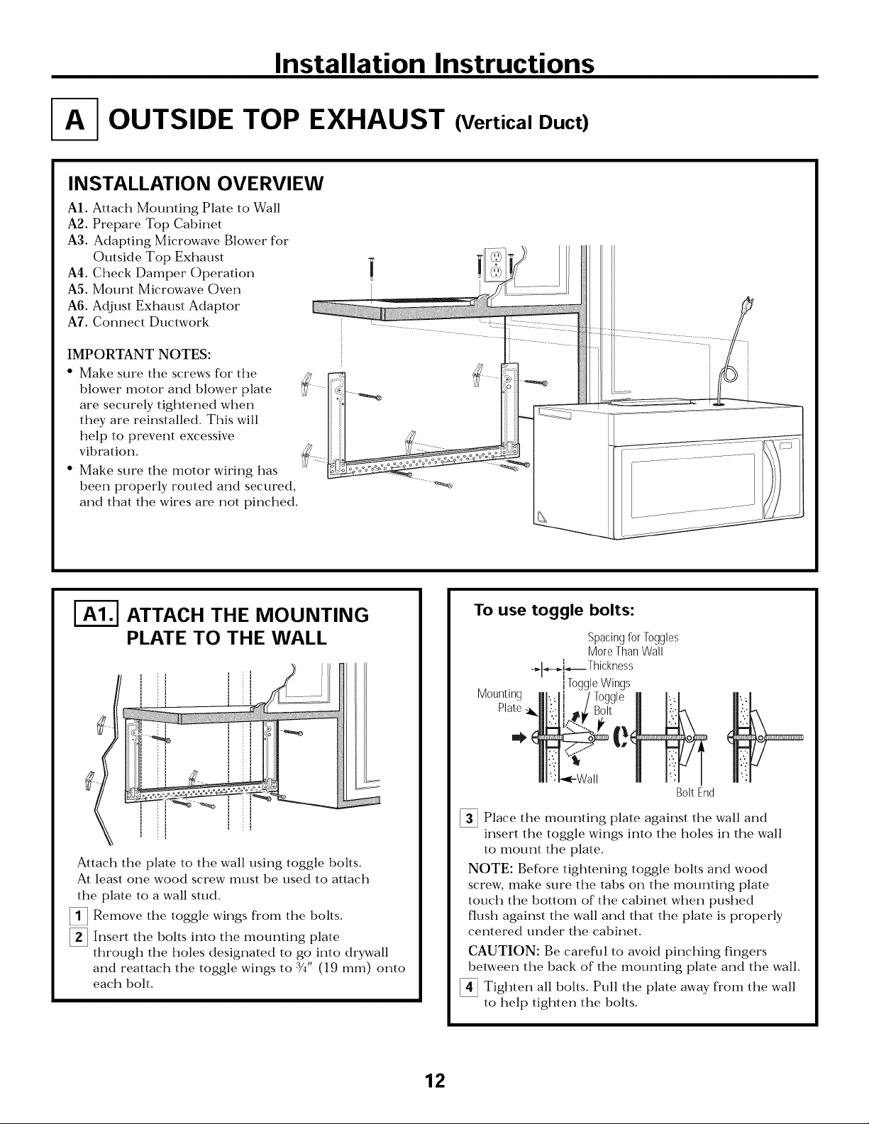
OUTSIDE TOP EXHAUST (Vertical Duct)
INSTALLATION OVERVIEW
A|. Attach Mounting Plate to Wall
A2. Prepare Top Cabinet
A3. Adapting Microwave Blower for
Outside Top Exhaust
A4. Check Damper Operation
A5. Mount Microwave Oven
A6. Adjust Exhaust Adaptor
A7. Connect Ductwork
IMPORTANT NOTES:
• Make sure the screws for the
blower motor and blower plate
are securely tightened when
they are reinstalled. This will
help to prevent excessive
vibration.
• Make sure the motor wiring has
been properly routed and secured,
and that the wires are not pinched.
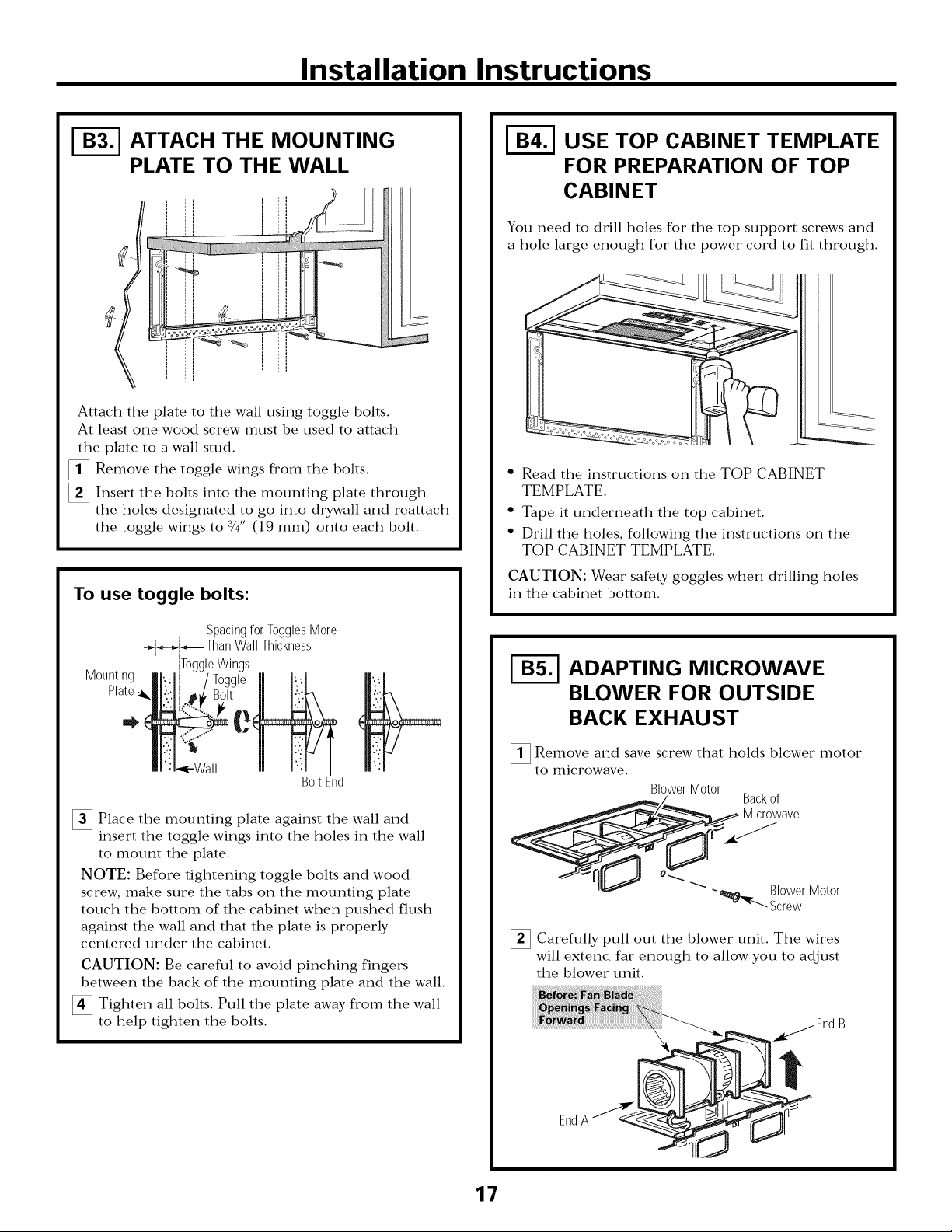
ATTACH THE MOUNTING
PLATE TO THE WALL
Attach the plate to the wall using toggle bolts.
At least one wood screw must be used to attach
the plate to a wall stud.
[]Remove the from the bolts.
[]Insert the bolts into the mounting
through the holes designated to go into drywall
and reattach the toggle wings to 3/4" (19 mm) onto
each bolt.
toggle
wings
plate
To use toggle bolts:
Spacing for Toggles
More Than Wall
-_l_i_--Thickness
I
Mounting
Plate,
]Place the mounting plate against the wall and
insert the toggle wings into the holes in the wall
to mount the plate.
NOTE: Before tightening toggle bolts and wood
screw, make sure the tabs on the mounting plate
touch the bottom of the cabinet when pushed
flush against the wall and that the plate is properly
centered under the cabinet.
CAUTION: Be careful to avoid pinching fingers
between the back of the mounting plate and the wall.
]Tighten all bolts. Pull the plate away fl'om the wall
to help tighten the bolts.
iToggle Wings
Bolt End
12
Page 13
Installation Instructions
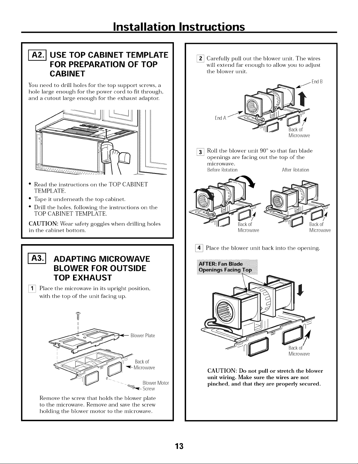
I-_ USE TOP CABINET TEMPLATE
FOR PREPARATION OF TOP
CABINET
You need to drill holes for the top support screws, a
hole large enough for the power cord to fit through,
and a cutout large enough for the exhaust adaptor.
• Read the instructions on the TOP CABINET
TEMPLATE.
• Tape it underneath the top cabinet.
• Drill the holes, following the instructions on the
TOP CABINET TEMPLATE.
CAUTION: Wear safety goggles when drilling holes
in the cabinet bottom.
Careflflly pull out the blower unit. The wires
will extend far enough to allow you to adjust
the blower unit.
jEnd B
EndA _P'_ _
Microwave
Roll the blower unit 90 ° so that fan blade
openings are facing out the top of the
microwave.
Before Rotation After Rotation
Backof
Microwave
Microwave
ADAPTING MICROWAVE
BLOWER FOR OUTSIDE
TOP EXHAUST
[] Place the microwave in its upright position,
with the top of the unit facing up.
?
I
I
_ BI0wer Plate
<l__---------._,_--__f] 1 Back0r
Micr0wave
Remove the screw that holds the blower plate
to the microwave. Remove and save the screw
holding the blower motor to the microwave.
[]Place the blower unit back into the opening.
CAUTION: Do not pull or stretch the blower
,ow r o,or
Screw
unit wiring. Make sure the wires are not
pinched, and that they are properly secured.
Backof
Microwave
13
Page 14
Installation Instructions
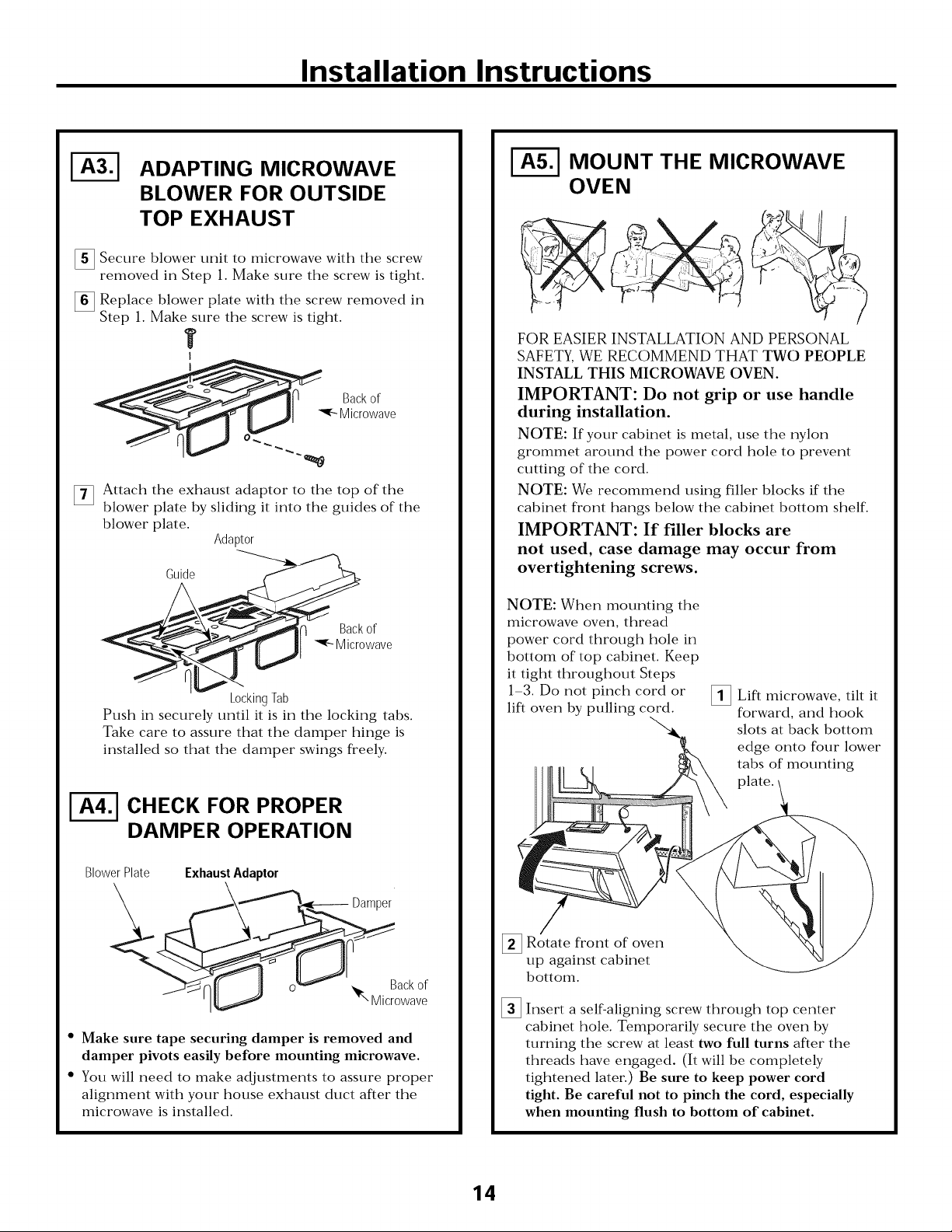
ADAPTING MICROWAVE
BLOWER FOR OUTSIDE
TOP EXHAUST
Secure blower unit to microwave with the screw
removed in Step 1. Make sure the screw is tight.
Replace blower plate with the screw removed in
Step 1. Make sure the screw is tight.
T
I
Back of
Micr0wave
Attach the exhaust adaptor to the top of the
[]
blower plate by sliding it into the guides of the
blower plate.
Adaptor
k0cking lab
Push in securely until it is in the locking tabs.
Take care to assure that the damper hinge is
installed so that the damper swings freely.
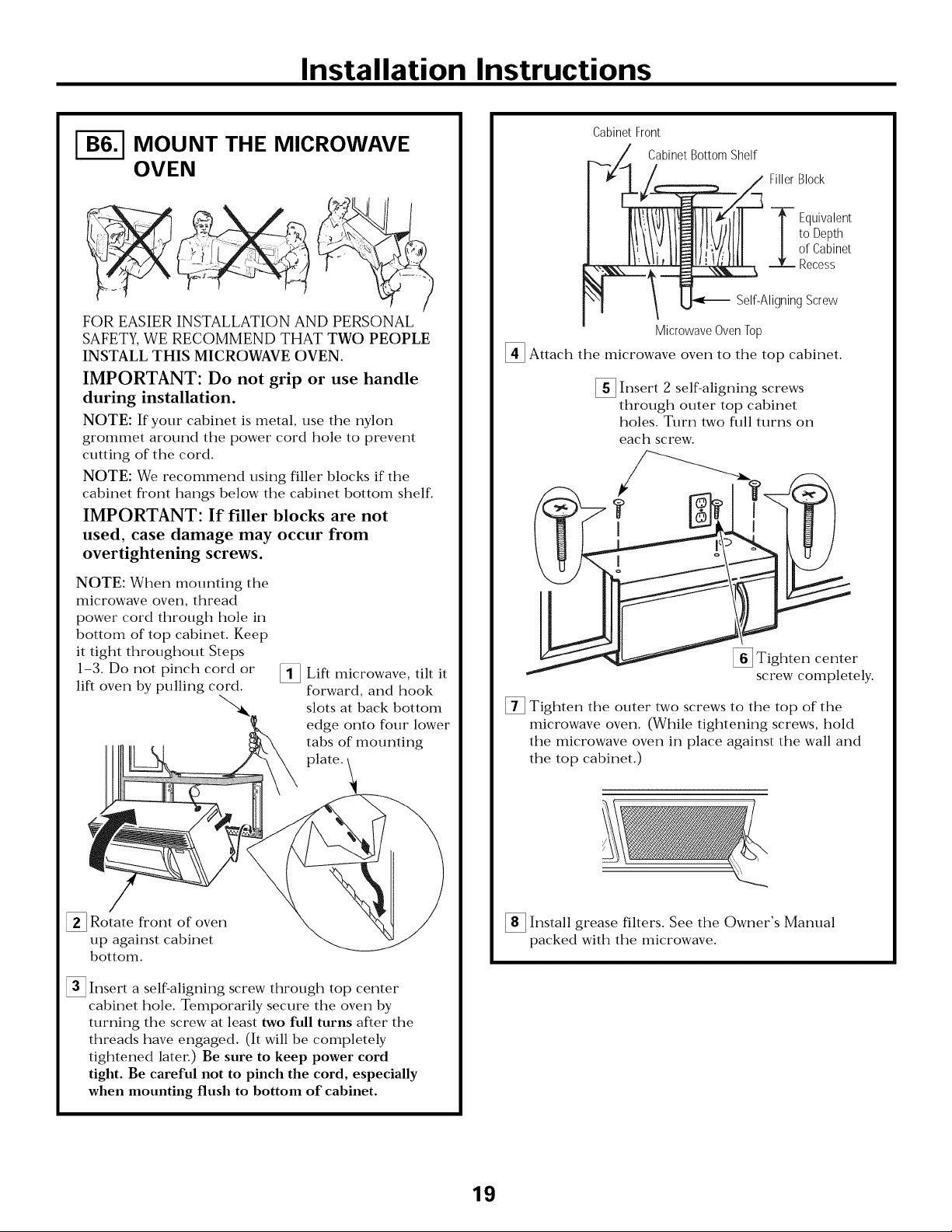
MOUNT THE MICROWAVE
OVEN
FOR EASIER INSTALLATION AND PERSONAL
SAFETY, WE RECOMMEND THAT TWO PEOPLE
INSTALL THIS MICROWAVE OVEN.
IMPORTANT: Do not grip or use handle
during installation.
NOTE: If your cabinet is metal, use the nylon
grommet around the power cord hole to prevent
cutting of the cord.
NOTE: We recommend using filler blocks if the
cabinet front hangs below the cabinet bottom shelf.
IMPORTANT: If filler blocks are
not used, case damage may occur from
overtightening screws.
NOTE: When mounting the
microwave oven, thread
power cord through hole in
bottom of top cabinet. Keep
it tight throughout Steps
1-3. Do not pinch cord or
lift oven by pulling cord.
[]Lift tilt it
microwave,
forward, and hook
slots at back bottom
edge onto four lower
tabs of mounting
plate.
I-_ CHECK FOR PROPER
DAMPER OPERATION
Blower Plate Exhaust Adaptor
X ,,_,,,___----Damper
• Make sure tape securing damper is removed and
damper pivots easily before mounting microwave.
• You will need to make adjustments to assure proper
alignment with your house exhaust duct after the
microwave is installed.
[]Rotate fl'ont of
up against cabinet
bottom.
%
Insert a self-aligning screw through top center
cabinet hole. Temporarily secure the oven by
turning the screw at least two full turns after the
threads have engaged. (It will be completely
tightened later.) Be sure to keep power cord
tight. Be careful not to pinch the cord, especially
when mounting flush to bottom of cabinet.
14
oven
Page 15
Installation Instructions
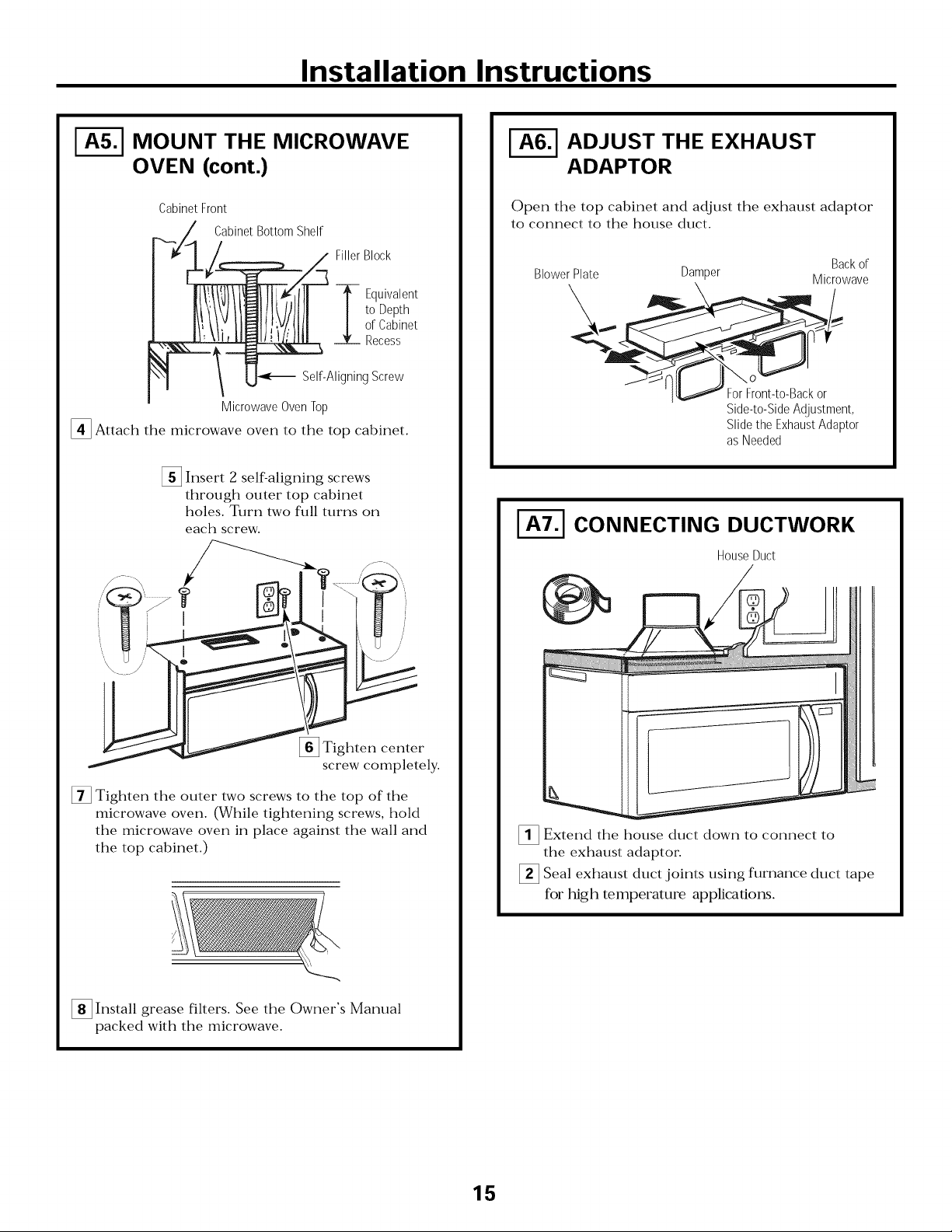
MOUNT THE MICROWAVE
OVEN (cont.)
Cabinet Front
..._._/_ Cabinet Bottom Shelf
/ Filler Block
/_,-- ;:::___
/ _F_[_/_ TEq uivalent
/ | : :bPitnhet
_:__!tI II:' _L Recess
J"\l !U _-_ Self-Aligning Screw
Microwave OvenTop
I_ Attach the microwave oven to the top cabinet.
[] Insert 2 self-aligning screws
through outer top cabinet
holes. Turn two flfll turns on
each screw.
ADJUST THE EXHAUST
ADAPTOR
Open the top cabinet and adjust the exhaust adaptor
to connect to the house duct.
Backof
BlowerPlate Damper Microwave
Side-to-SideAdjustment,
Slidethe ExhaustAdaptor
asNeeded
I-_ CONNECTING DUCTWORK
HouseDuct
[]Tighten center
screw completely.
[] Tighten the outer two screws to the top of the
microwave oven. (While tightening screws, hold
the microwave oven in place against the wall and
the top cabinet.)
[] Install grease filters. See the Owner's Manual
packed with the microwave.
]Extend the house duct down to connect to
the exhaust adaptor.
]Seal exhaust duct joints using furnance duct tape
for t_gh temperature applicatiorgs.
15
Page 16
Installation Instructions
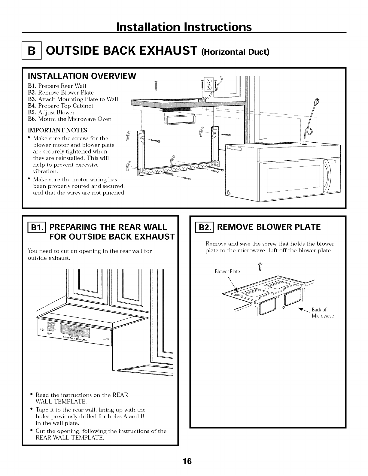
OUTSIDE BACK EXHAUST (Horizontal Duct)
INSTALLATION OVERVIEW
BI. Prepare Rear Wall
B3. Remove Blower Plate
B3. Attach Mounting Plate to Wall
B4. Prepare Top Cabinet
BS. Adjust Blower
B6. Mount the Microwave Oven
IMPORTANT NOTES:
• Make sure the screws for the
blower motor and blower plate
are securely tightened when
they are reinstalled. This will
help to prevent excessive
vibration.
• Make sure the motor wiring has
been properly routed and secured,
and that the wires are not pinched.
PREPARING THE REAR WALL
FOR OUTSIDE BACK EXHAUST
You need to cut an opening in the rear wall for
outside exhaust.
• Read the instructions on the REAR
WALL TEMPLATE.
• Tape it to the rear wall, lining up with the
holes previously drilled for holes A and B
in the wall plate.
• Cut the opening, following the instructions of the
REAR WALL TEMPLATE.
REMOVE BLOWER PLATE
Remove and save the screw that holds the blower
plate to the microwave. Lift off the blower plate.
Blower Plate
l _ _ _ Backof
Microwave
16
Page 17
Installation Instructions
_] ATTACH THE MOUNTING
PLATE TO THE WALL
Attach the plate to the wall using toggle bolts.
At least one wood screw must be used to attach
the plate to a wall stud.
]Remove the toggle wings from the bolts.
]Insert the bolts into the mounting plate through
the holes designated to go into drywall and reattach
the toggle wings to 3/4" (19 mm) onto each bolt.
To use toggle bolts:
USE TOP CABINET TEMPLATE
FOR PREPARATION OF TOP
CABINET
You need to drill holes for the top support screws and
a hole large enough for the power cord to fit through.
• Read the instructions on the TOP CABINET
TEMPLATE.
• Tape it underneath the top cabinet.
• Drill the holes, following the instructions on the
TOP CABINET TEMPLATE.
CAUTION: Wear safety goggles when drilling holes
in the cabinet bottom.
Spacing for Toggles More
_-_i_,---Than Wall Thickness
Mounting
Plate
]Place the mounting plate against the wall and
insert the toggle wings into the holes in the wall
to mount the plate.
roggle Wings
Bolt End
NOTE: Before tightening toggle bolts and wood
screw, make sure the tabs on the mounting plate
touch the bottom of the cabinet when pushed flush
against the wall and that the plate is properly
centered under the cabinet.
CAUTION: Be careflfl to avoid pinching fingers
between the back of the mounting plate and the wall.
Tighten all bolts. Pull the plate away from the wall
to help tighten the bolts.
ADAPTING MICROWAVE
BLOWER FOR OUTSIDE
BACK EXHAUST
[]Remove and that holds blower motor
to microwave.
Careflflly pull out the blower unit. The wires
will extend far enough to allow you to adjust
the blower unit.
save screw
Blower Motor
_" - _ Blower Motor
v .,_ Screw
17
EndA
Page 18
Installation Instructions
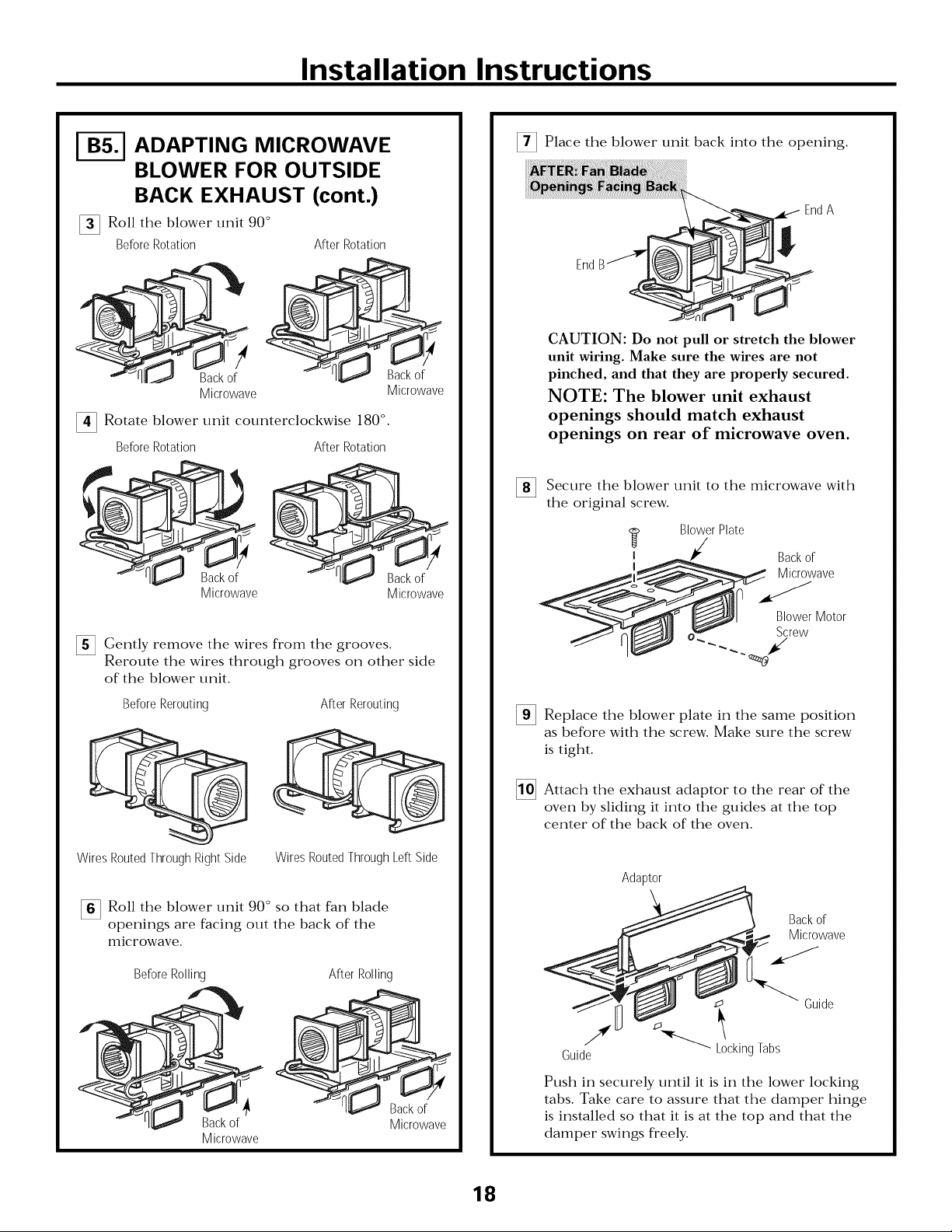
ADAPTING MICROWAVE
BLOWER FOR OUTSIDE
BACK EXHAUST (cont.)
[] Roll the blower" unit 90 °
Before Rotation After Rotation
Microwave
Rotate blower unit counterclockwise 180 ° .
Before Rotation
Back of
Microwave
[]Gently remove the wires from the
Reroute the wires through grooves on other side
of the blower unit.
After Rotation
grooves.
Backof
Microwave
Back of
Microwave
[]Place the blower unit back into the opening.
EndA
End
CAUTION: Do not pull or stretch the blower
unit wiring. Make sure the wires are not
pinched, and that they are properly secured.
NOTE: The blower unit exhaust
openings should match exhaust
openings on rear of microwave oven.
[ ecure the blower unit to the microwave with
the original screw.
Blower Plate
,!_ Microwave
I _ Back of
Blower Motor
Screw
Before Rerouting After Rerouting
Wires Routed ThroughRight Side Wires Routed Through Left Side
_6_ Roll the blower unit 90 ° so that fan blade
openings are facing out the back of the
microwave.
Before Rolling
Microwave
After Rolling
Back of
Microwave
[]Replace the blower in theplate
as before with the screw. Make sure the screw
is tight.
[]Attach the exhaust the of theadaptor
oven by sliding it into the guides at the top
center of the back of the oven.
same
to Fear
Adaptor
o
Guide
Push in securely until it is in the lower locking
tabs. Take care to assure that the damper hinge
is installed so that it is at the top and that the
damper swings freely.
Locking Tabs
position
Backof
Microwave
Guide
18
Page 19
Installation Instructions
MOUNT THE MICROWAVE
OVEN
FOR EASIER INSTALLATION AND PERSONAL
SAFETY, WE RECOMMEND THAT TWO PEOPLE
INSTALL THIS MICROWAVE OVEN.
IMPORTANT: Do not grip or use handle
during installation.
NOTE: If your cabinet is metal, use the nylon
grommet around the power" cord hole to prevent
cutting of the cord.
NOTE: We recommend using filler blocks if the
cabinet front hangs below the cabinet bottom shelf.
IMPORTANT: If filler blocks are not
used, case damage may occur from
overtightening screws.
Cabinet Front
Cabinet Bottom Shelf
FillerBlock
-_ Equivalent
to Depth
of Cabinet
Recess
Self-Aligning Screw
Microwave Oven Top
[]Attach the microwave oven to the top cabinet.
[] Insert 2 self-aligning screws
through outer top cabinet
holes. Turn two flfll turns on
each screw.
NOTE: When mounting the
microwave oven, thread
power cord through hole in
bottom of top cabinet. Keep
it tight throughout Steps
1-3. Do not pinch cord or"
lift oven by pulling cord.
[]Rotate fl'ont of
up against cabinet
bottom.
[]Insert a self-aligning screw through top center
cabinet hole. Temporarily secure the oven by
turning the screw at least two full turns after the
threads have engaged. (It will be completely
tightened later:) Be sure to keep power cord
tight. Be careful not to pinch the cord, especially
when mounting flush to bottom of cabinet.
oven
[]Lift tilt it
microwave,
forward, and hook
slots at back bottom
edge onto four lower
tabs of mounting
plate.
[]Tighten center
screw completely.
[] Tighten the outer two screws to the top of the
microwave oven. (While tightening screws, hold
the microwave oven in place against the wall and
the top cabinet.)
[] Install grease filters. See the Owner's Manual
packed with the microwave.
19
Page 20
Installation Instructions
RECIRCULATING (Non-Vented Ductless)
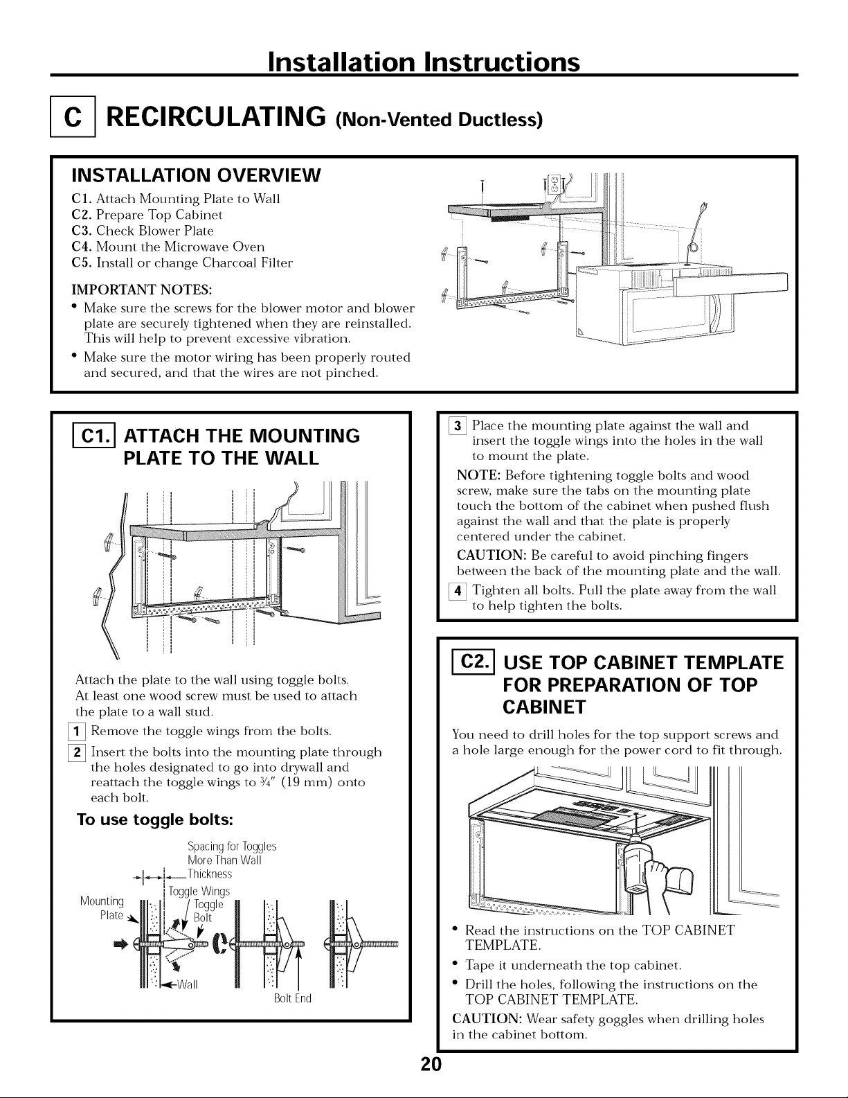
INSTALLATION OVERVIEW
C1. Attach Mounting Plate to Wall
C3. Prepare Top Cabinet
C3. Check Blower Plate
C4. Mount the Microwave Oven
C5. Install or change Charcoal Filter
IMPORTANT NOTES:
• Make sure the screws for the blower motor and blower
plate are securely tightened when they are reinstalled.
This will help to prevent excessive vibration.
• Make sure the motor wiring has been properly routed
and secured, and that the wires are not pinched.
ATTACH THE MOUNTING
PLATE TO THE WALL
Attach the plate to the wall using toggle bolts.
At least one wood screw must be used to attach
the plate to a wall stud.
[]Remove the from the bolts.toggle wings
Insert the bolts into the mounting plate through
the holes designated to go into drywall and
reattach the toggle wings to 3/4" (19 mm) onto
each bolt.
To use toggle bolts:
]Place the mounting plate against the wall and
insert the toggle wings into the holes in the wall
to mount the plate.
NOTE: Before tightening toggle bolts and wood
screw, make sure the tabs on the mounting plate
touch the bottom of the cabinet when pushed flush
against the wall and that the plate is properly
centered under the cabinet.
CAUTION: Be careful to avoid pinching fingers
between the back of the mounting plate and the wall.
Tighten all bolts. Pull the plate away from the wall
to help tighten the bolts.
I-_ USE TOP CABINET TEMPLATE
FOR PREPARATION OF TOP
CABINET
You need to drill holes for the top support screws and
a hole large enough for the power cord to fit through.
Mounting
Plate,
Spacing for Toggles
More Than Wall
÷l_-_.i_,----Thickness
I
lToggle Wings
Bolt End
• Read the instructions on the TOP CABINET
TEMPLATE.
• Tape it underneath the top cabinet.
• Drill the holes, following the instructions on the
TOP CABINET TEMPLATE
CAUTION: Wear safety goggles when drilling holes
in the cabinet bottom.
2O
Page 21
Installation Instructions
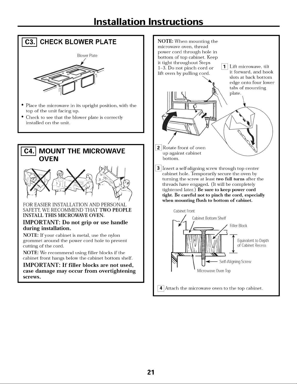
CHECK BLOWER PLATE
Blower Plate
• Place the microwave in its upright position, with the
top of the unit facing up.
• Check to see that the blower plate is correctly
installed on the unit.
MOUNT THE MICROWAVE
OVEN
FOR EASIER INSTALLATION AND PERSONAL
SAFETY, WE RECOMMEND THAT TWO PEOPLE
INSTALL THIS MICROWAVE OVEN.
IMPORTANT: Do not grip or use handle
during installation.
NOTE: If your cabinet is metal, use the nylon
grommet around the power cord hole to prevent
cutting of the cord.
NOTE: We recommend using filler blocks if the
cabinet front hangs below the cabinet bottom shelf.
IMPORTANT: If filler blocks are not used,
case damage may occur from overtightening
screws.
NOTE: When mounting the
microwave oven, thread
power cord through hole in
bottom of top cabinet. Keep
it tight throughout Steps
1-3. Do not pinch cord or
lift oven by pulling cord.
[]Rotate front of oven
up against cabinet
bottom.
[]Insert a self-aligning screw through top center
cabinet hole. Temporarily secure the oven by
turning the screw at least two full turns after the
threads have engaged. (It will be completely
tightened later.) Be sure to keep power cord
tight. Be careful not to pinch the cord, especially
when mounting flush to bottom of cabinet.
Cabinet Front
Cabinet Bottom Shelf
MicrowaveOvenTop
[]Lift microwave, tilt
it forward, and hook
slots at back bottom
edge onto four lower
tabs of mounting
plate.
Filler Block
Equivalentto Depth
of CabinetRecess
Self-AligningScrew
[]Attach the microwave oven to the top cabinet.
21
Page 22

Installation Instructions
MOUNT THE MICROWAVE
OVEN (cont.)
[] Insert 2 self-aligning screws
through outer top cabinet
holes. Turn two full turns on
each screw.
I
[]Tighten center
screw completely.
[] Tighten the outer two screws to the top of the
microwave oven. (While tightening screws, hold
the microwave oven in place against the wall and
the top cabinet.)
_-_ INSTALLING OR CHANGE
THE CHARCOAL FILTER
NOTE: The charcoal filter is factory installed in
recirculating models. Follow these steps to replace a
filter or to install a filter after converting a vented
model to recirculating operation.
[] Remove screws on top of grille using a
#1 Phillips screwdriver'.
[] Open the door.
[] Remove the grille.
Pull the grille straight off.
Charcoal
Filter
I
I
[] Install grease filters. See the Owner's Manual
packed with the microwave.
[] Install the charcoal filter: Insert filter upper
in the unit and then pull down filter. When
properly installed, the wire mesh of the filter
should be visible fl'om the fl'ont.
Insert
[] Replace the grille and the screws.
[] Close the door.
22
Page 23

Installation Instructions
BEFORE YOU USE YOUR MICROWAVE
Make sure the microwave oven has been
installed according to instructions.
r_ emove all packing material from the
microwave oven.
r_ Install turntable ring and glass tray in cavity
I
Read the USE & CARE Manual.
F_ EEP INSTALLATION INSTRUCTIONS
FOR THE LOCAL INSPECTOR'S
USE.
I
-_ Replace house fuse or turn breaker back on.
Plug power cord into a dedicated 15- to 20-amp
%
electrical outlet.
Ensure proper
groundexists/
before use
F_ FILL OUT PRODUCT REGISTRATION CARD
23
Page 24

instructions
Foura micro-on
es
d'installation
| |
ides questions? Appelez au1"8^00"94^4"9044^(US). ,o. ,,i_i_ ,>_,.__i_web:http://www.frigidaire.com I
7-uuu-z_,_-ua,_z_anaoa)
i
AVANT DE COMMENCER
Lisez attentivement routes ces instructions.
•IMPORTANT - ('_onservezces instructions
pour Finspecteur local.
rbglements en vigueur.
• Remarque destin6e a l'installateur - A_,,-_-
vous de laisser ces instructions au co11soi/li/la[et/i.
* Remarque destin6e au consommateur -
Conservez ces instructions pour xx)us y reporter
ult6rieurement.
o Niveau de comp6tence - L'installation de cet appareil
n6cessim des comp6tences de base en m6canique et en
_lectricit_.
o L'installateur est responsable de la qualit_ de l'installation.
o Une panne caus_e par une maux_fise installation n'est pas
couverte par la garantie du produit.
VEUILLEZ LIRE ATTENTIVEIVlENT.
CONSERVEZ CES iNSTRUCTiONS.
pin 316495063
Mars 2010
Page 25

instructions d'installation
iNDEX •
Renseignements g6n6raux
Mesures de s6curR6 importantes ...................................... 3
Exigences 61ectfiques ........................................................ 3
Dommages- Exp6dition/installation ................................ 4
Pibces comprises .............................................................. 4
Outils n6cessaires .............................................................. 5
D6gagements pour l'installation ........................................ 5
Guide d'installation 6tape par 6tape
Installation de la plaque de montage .............................. 6-8
Enl_vement de la plaque de montage .................... (;
Localisation des montants ........................................ 6
t_tablissement de l'emplacement
de la plaque murale .................................................. 7
Alignement de la plaque murale ............................. 8
Types d'installation ..................................................... 9-22
t_wmuation de la hotte ................................................ 10-11
FC-] Rec)clage d'ah 90 99
Fixation de la plaque de montage au tour ....20
Preparation de l'armohe sup&ieme ............ 20
V&ification de l'plaque du ventilateur. ......... 21
Installation du fore k micro-ondes ........ 21-22
Installation ou changemeut
Avant d'utiliser votre four R miero-ondes ........................ 23
99du filtre k charbon ............................................
N
Evacuation _'_l'ext&ieur par le dessus .............. 12-1 5
Fixation de la plaque de montage au tour ....1 2
Prdparation de l'armoire sup(:rieure ............ 13
A.iusmment du venfilamur. .......................... 13-14
V&'ification du fbnctionnement
du registre ........................................................ 14
Installation du fi)ur _'_micro-ondes .......... 14-15
Ajustement de l'adaptateur d'_wlcuation ...... 15
Connexion au conduit .................................... 15
Evacuation _'_l'ext&ieur par l'arribre ................ 16-1.
Preparation du tour artiste pour
F_wmuation _'_Fext&ieur par Farribre .......... 16
Enlbvement de l'plaque du ventilamtn". ............ 16
Fixation de la plaque de montage au tour ....1 7
Preparation de Farmohe sup&ieure ............ 17
Adaptation du ventilateur du fbur
_'_micro-ondes pour l'_w_cuation
_'_Fext&ieur par Farribre .......................... 17-18
Installation du fbur _'_micro-ondes ................ 19
" 9
2
Page 26

instructions d'installation
IVlESURES DE SECURITE ilVIPORTANTES
Ce produit nOcessite une prise de courant _'ltrois alvOoles
raise _'lla terre. Avant d'entreprendre Finstallation,
Finstallateur dolt v6rifier la continuit6 de la raise _'_la terre
de la boite de la prise de courant pour s'assmer que cetm
dernibre est correctement raise _'lla terre. Sice n'est pas le
cas, ou si la boite ne r_pond pas aux exigences _lectriques
indiqu_es (k la section EXIGEN('£S t_LE('_TRIQUES), il flint
fidre appel _'_un _lectricien qualifi6 pour corriger tout
d_fimt.
ATTENTION: Pour votre
s_curit_, enlevez le fusible ou
d_clenchez le disjoncteur au
panneau de distribution
principal avant
d'entreprendre l'installation,
afin d'6viter toute blessure
grave ou mortelle imputable
un choc 61ectrique.
ATTENTION : Pour votre s6curit6, la surface de montage
dolt 6tre en mesure de supporter la charge des armoires,
ainsi qu'un poids suppl6mentaire de 28,5 _ 38,5 kg (63
85 lb) correspondant au poids du produit, et la charge du
four qui peut atteindre 22,7 kg (50 lb), pour un poids total
de 51,3 h 61,2 kg (113 h 135 lb).
ATTENTION : Pour votre s6curit6, ce produit ne doit pas
6tre install6 avec des armoires am6nag6es en ilot ou en
p6ninsule. 11doit 6tre fix6 A LA FOIS _ une armoire
sup6rieure ET _un mur.
REMARQUE : Pour faciliter l'installation et pour votre
s6curit6, l'installatinn de ce produit doit 6tre effecm6e par
deux personnes.
IMPORTANT - VEUILLEZ LIRE ATTENTIYEMENT.
POUR VOTRE SI_]CUR1TI_],CET APPAREIL DOIT 1}]TRE
CORRECTEMENT MIS A LA
TERRE POUR 14]VITERUN
CHOC GRAVE OU
MORTEL.
Demandez _tm 61ectricien qualifi6 de v6rifier la prise
murale et le circuit 61ectrique pour vous assurer que la prise
est correctement raise h la terre.
Si la prise murale est du t}_pe standard _ deux alv6oles, il est
trSs important de la faire remplacer par une prise _ trois
alv6oles correctement raise _ la terre en vous adressant _un
61ectricien qualifi6.
NE COUPEZ, NE DI_FORMEZ ET NE RETIREZ EN
AUCUN CAS UNE DES BROCHES DE LA FICHE DU
CORDON D'ALIMENTATION. N'UTILISEZ PAS DE
RALLONGE.
EXIGENCES
ELECTRIQUES
Les caract&istiques nominales de ce produit sont : 120 V
(_A, 60 Hz, 15 A et 1,6 kW. Ce produit dolt &tre branch_ _'l
un circuit d'alimentation de mnsion et de fldquence
appropri6es. La grosseur des ills dolt &tre contbrme aux
exigences du Code national d'dlectricitd ou du code local en
vigueur pour cette puissance nominale. La fiche du cordon
d'alimentation dolt &tre branchde dans une prise de courant
distincm raise _'_la terre, de 15 ou 20 amperes. La boite de la
prise dolt &tre am6nag6e dans l'armoire situ6e au-dessus du
tbur _'_micro-ondes. La boite de la prise et le circuit
d'alimentation doivent &tre installds par un dlectricien
qualifi6, confi)rm6ment aux normes du Code national
d'_lectricit_ ou du code local en vigueur.
Assurez-vous
qu'une mise
la terre
appropri@ est en
place avant toute utilisation
Pour diminuer les risques de
choc 61ectrique, le cordon
d'alimentation de cet appareil
est muni d'une fiche _ trois
broches (raise _ la terre) qui
correspond _une prise
murale _ trois alv6oles, raise
la terre.
3
Page 27

instructions d'installation
DOIVINIAGES
EXPEDITION/
iNSTALLATiON
• Si l'appareil est endommag_ durant le
transport, retournez-le au magasin ot'_ w_us l'avez
achet0 pour r0paration ou remplacement.
• Si l'appareil est endommag_ par le client, la rdparation ou
le remplacement reste _ la charge du client.
• Si l'appareil est endommag_ par l'installateur (s'il s'agit
d'une personne difl_rente du client), la rdparation ou le
remplacement doivent/;fire l'objet d' une entente entre le
client et l'installamur.
PIECES COMPRISES
SACHET
PIECE
/
/
DE QUiNCAiLLERiE
Vis _ bois 2
(1/4 x 2 po)
Boulons _ ailettes 4
(et Qcrous_ oreilles)
(3/16 x 3 po)
] Vis _ m_taux _ 3
auto-alignement
I(1/4 po - 28 x 3-1/4 po)
m
QUANTITE
PIECES COMPRISES
SACHET DE QUINCAILLERiE
PIECE
Gabarit pour.
armoiresuper,eure
et Gabarit pour
mur arri6re
combi@
Instructions
d'installation
Filtres
graisses
emball_s
s@ar_ment
Adaptateur
deconduit
d'_vacuation
QUANTITE
Passe-ill en nylon (pour 2
armoires en m_tal)
L m
Attache pour cordon 1
d'alimentation (en
plastique)
Vous tromerez les pibces de quincaillerie dans tm sachet
fimrni avec l'appareil. V_rifiez que vous a_ez recu routes
ces piOces.
REMARQUE : Des pibces suppldmentaires sont incluses.
Plateauenverre
Anneaude
plateautournant
4
Page 28

instructions d'installation
OUTILS NECESSAIRES
TournevisPhillipsno1 Crayon
Cisaillesdeferblantier
(pourcouperle registre,
si necessaire)
Gants
Ciseaux(pourcouperle
gabarit,si necessaire)
Regleourubanamesurer
_ droite
Perceuseelectriqueavecforets
de3/16, 1/2 et 5/8 po
Equerredemenuisier
(facultative)
Entretoisesd'assemblageoupieces
de boisderecuperation,si besoin
est,pourI'espacementavec
I"armoiresuperieure(utiliseespour
I'installationsousunearmoiredont
le fondest doted'un rebord)
Scie(sauteuse,trepanoua guichet)
Lunettesdesecurite
Localisateurde eu Marteau(facultatif)
montant
Niveau
DEGAGEIVlENTS POUR UINSTALLATION
REMARQUES :
* I1 flint un espace d'au moins 30 po (76,2 cm) entxe les
_lI'I/]oiI'es, S_l]S obstI'[/c[iol]s.
• Si l'_acuation de Fail" de votre fi)ux" _'lmicro-ondes
s'eflbctue vexs Fext&ieux, consultez la section
<<E_acuation de la hotte potu" la p_'_pa_'ation du conduit
d'_xacuation >>.
• Lorsque vous installez le four _ micro-ondes sous des
armoires dont le fond est lisse et plat_ suivez
attentivement les instructions du gabarit pour armoire
sup_rieure concernant le d4gagement du cordon
d'alimentatinn.
Aumoins66po
(167,6cm)entre
le solet le
dessusdufour
micro-ondes
I
Dosseret
Rebordinferieurde
I'armoirea30 po
minimum
de lasurface
decuisson
Rubanadhesifentoile et ruban-cache
5
Page 29

instructions d'installation
Fq INSTALLATION DE LA PLAQUE DE MONTAGE
ENLEVEMENT DU FOUR A
MICRO-ONDES DE LA BOJTE/
ENLE;VEMENT DE LA PLAQUE
DE MONTAGE
_-] Reti*'ez les di*'ectixes d'installation, les filtres, le plateau
en vexxe et Ie sachet de quincaillerie. N'enlevez pas la
protection en polystyrene du devant du four.
_] Repliez complbtement Ies quatre ,abats cnntre les cC)tds
de la boite. Ensuite, _etoumez le fbu_ et Ia boite avec
px_caution. Le tbu, dexxait ,epose, sur le pol)st_rbne.
Polystyrene
_] Ti*'ez la boite vex's le haut pou*" d_gagex" le fimx'.
_'] ('_oupez le centre du sac en plastique pou, ,eti,e, la plaque
de montage
Plaquede
Vis_ montage
LOCALISATION DES MONTANTS
Montants i
Centre' i_ i '
_] Localisez les montants en utilisant une des m_thodes
suix_mtes :
A. Localisamu, de montant- dispositif
magn_tique peHnettant de localise, les clous.
OU
g. Utilisez un F¢_aiteau potn f_appe_ l_g_ement su_ la
stnfhce de montage.jusqu'a ce que x_)us
n'enmndiez plus un son cx'eux. Cela signifie que
v()/ls avez tI'ouve un montant.
_'] Apx'as a_oi*"localis8 le(s) montant(s), txou_,ez-en le
centxe en sondant le mu, fi Faide d'un petit clou afin de
trouver les reboxds du monmnt. Puis fhites une maxque
_'_mimhemin entre les deux boxds. Le centre de tout
montant ad.jacent dolt se tIOUVei _'_]6 po (40,6 cm) ou
24 po (61 cm) de cette maique.
_] Tiacez une ligne veiticale maiquant Ie milieu des
montants.
LEf_OUR,kMmRO-ONDESDOlT fZTREf_Xf:,k
AU MOINS UN MONTANT DU MUR.
_] Enlexez les xis de la plaque de montage. ('_ette plaque se,a
utilis_e comme gaba,it pour le mtu aHi&,e et pou, le
montage. Remettez en place les vis ,eti,_es
p,_alablement.
6
Page 30

instructions d'installation
I_TABLISSEMENT DE UEMPLACEMENT DE LA PLAQUE MURALE SOUS
VOTRE ARMOIRE
Emplacement de la plaque = Emplacement de la plaque =
sous une armoire b fond plat sous une armoire dot_e d'un rebord
Languettesde la plaquede montage
touchantle dessousde I'armoire
Aumoins30 po(762 cm),
moinsde36 po (91,4cm)
Emplacement de la plaque - sous une
armoire dot_e d'un rebord avant
Languettesde la plaquede
montagetouchantlerebordarriere
\
I
I
I delasurface
Vos armoixes peuvcnt &txe dot_es de gaxnitmes
d_co_'atives qui entravent Finstallation du micro-ondes.
Enlevez l'_l&nent d_co,atif pore installe, convenablement
le fore" _'_mic,o-ondes et pore vous assme, qu'il est de
decuisson
i
Languettes de la plaque de
montage plac0es sous le
fond de I'armoire a une
distance 0gale a I'0paisseur
du rebord avant de I'armoire
, %
II , A 30 po(76,2cm)de
la surfacedecuisson
LE FOUR A MICRO-ONDES DOIT I_]TRE DE NIVEAU.
Utilisez un niveau pore x_)us assme, que le tbnd de
l'aHnohe est de niveau.
Si les armoi,es sont dot&es uniquement d'un ,ebord awmt,
sans ,ebo,d sin les c6t_s ou _'_l'a,Ti&,e, installez la plaque de
montage plus bas, _:lla m_me distance que le _ebo_d awmt
de l'aHnoi,e. Ainsi, le fbm se,a de niveau.
Mesmez la hautem h_t&ieme du ,ebmd axant de
] ' a I't/10 ] I'e.
T,acez tree ligne hmizontale sous le fired de Farmoi,e,
sin le ram aHib,e _'_tree distance _quivalente k la
longueu, int&ieme du ,ebmd axant de FaHnoi,e.
Pore l'installation sous une aHnoi,e dot&e d'un ,ebo,d
awmt uniquement, alignez les languettes de montage
sin cetm ligne hofizontale, sans qu'elles touchent le
fbnd de FaHnohe, tel que d_cfit _'_F_tape D.
Page 31

instructions d'installation
| ALIGNEMENT DE LA PLAQUE MURALE
TrouA
Encochesde la i I'armoiresup6rieure
ligne centrale I
i
l
I
l
i
I-'<'_ Tracezuneligne
i verticalesurle tour
i partirdu centrede
l
ATTENTION : Portez T
des gants pour 6_iter TrouC
de _ous blesser sur les
bords coupan ts,
ri1
Tracez une ligne verticale sin le tour au centre de l'espace
de 30 po (76,2 cm) de large.
%
Utilisez la plaque de montage comme gabarit pour le tour
arribre. Placez la plaque de montage sur le tour, en vous
assurant que les [anguettes touehent le fond de l'armoire
on la ligne de niveau trae_e h l%tape C dans le eas des
armoires dot_es d'tm rebord avant. Alignez l'eneoehe et la
ligne eentrMe de la plaque de montage sur la ligne eentrMe
trac_e sur le tour.
%
Tout en tenant la plaque de montage d'une main, tracez
des cercles sin le tour au niveau des trous A, B, C et D
(v(uez le sch6ma plus haut/la plaque r6eHe est pourvue
de flbches). Quatre trous doivent _tre utilis_s pour le
montage.
ZoneE
i
/
REMARQUE : Si aucun des trous C et D ne se trou'_ dans
1111 i/lontant, tFouvez 1111 I/lont_lnt dans ]a zone g et tracez
un cinquibme cercle pour l'aligner sur un mnnmnt. I1 est
important qu'au moins une vis g bois soit fix_e solidement
darts un montant pour soumnir le poids du fbur ;i micro-
ondes.
TrouD
Mettez la plaque de montage de c6t_.
N
Percez des trous dans [es cercles. S'il y a un montant,
percez un trou de :_/16po (48 ram) pour les vis _'_bois. S'il
n'y a pas de montant, percez un trou de 5/8 po (16 ram)
pour des bouh:ms _:lailettes.
REMARQUE : NE FIXEZ PAS LA PLAQUE DE
MONTAGE MAINTENANT.
Page 32

instructions d'installation
TYPES D'INSTALLATION (Choisissez A, B ou C)
Ce fbur _'_micro-ondes est concu pour s'adapter aux trois _'pes
d'_w_cuation suivants :
A. l_]vacuation R l'ext_rieur par le dessus (conduit vertical)
B. l_]vacuation R l'ext_rieur par l'arrii_re (conduit horizontal)
C. Recyclage (sans condui0
_ VACUATION A L'EXTi_RIEUR PAR
LE DESSUS (CONDUIT VERTICAL)
Adaptateur en place
pour une 0vacuation
I'ext6rieur par le dessus
REMARQUE : Ce fi)ur _'_micro-ondes est dquipd _'_l'usine en vue
d'une Recyclage.
Choisissez le _'pe d'_x_cuation appropri_ _'_x_)tre installation et
rendez-vous _'_cettc section.
[B_ I_VACUATION A L'EXTi_RIEUR PAR
L'ARRIERE (CONDUIT HORIZONTAL)
L'adaptateurdolt 6treplac0
l'arrierepourune6vacuation
iere
_C-_ RECYCLAGE D'AIR
(F:VACUATION SANS CONDUIT)
Sur les modbles concus pour le
rec)vlage d'air, un filtre _'_
charbon.jetable est installd en
usine pour retenir ]a f um_e et les
odeurs.
Page 33

instructions d'insta||ation
INSTRUCTIONS POUR L'INSTALLATION EXTERIEURE
DE CODUITS D'ECHAPPEMENT.
REMARQUE : Si _)us devez installer des conduits, notez que la
lnngueur totale du conduit rectangulaire de 3-1/4 pox 10 po
(8,2 x 25,4 cm) nu du conduit fond de 6 po (15,2 cm)/5 po
(10,5 cm) de diambtre ne dolt pas 6tre sup6rieure _ 120 pi
(36,5 m) de longueur 6quivalente
L'_vacuation vers l'ext&ieur requiert un CONDUIT
D't_VACUATION POUR HOTTE. Lisez attentivement ce qui
suit.
REMARQUE : I1 est important que l'&_cuatinn soit install_e en
utilisant le chemin le plus direct et avec le moins de coudes
possible. Cela assme une bonne _vacuatinn et aide a pr_venir
les blncages. Assurez-vous 6galement que les registres bougent
librement et que rien ne bloque les conduits.
Connexion au conduit :
La sortie d'_vacuation de la hotte a _t_ concue pour &tre
raccordde ;'_un conduit rectangulaire standard de 3-1/4 x 10 po
(8,2 x 25,4 cm).
Si vous avez besoin d'un conduit fond, il flint utiliser un
adapmmur de transition. N'utilisez pas un conduit dont le
diami_tre est inf_rieur _ 6 po (15,2 era).
LONGUEUR
PI#CES DE CONDUIT
Adaptateurdetransition*
EQUIVALENTE
5pi (1,5m)
Longueur maximale du conduit :
Pour une circulation d'air satisfifisante, la longueur tnmle du
conduit recmngulaire de 3-1/4 x 10 po (8,2 x 25,4 cm) ou du
conduit fond de 6 po (15,2 cm)/5 po (10,5cm)de diambtre ne
dolt pas exc6der une longueur 6quivalente g 120 pi (36,5 m)
Les coudes, adaptateurs de transition,
_vents muraux ou de toiture, etc. oment une
r_sistance suppl&nentaire ;'_la circulation de Fair et sont
_quix_dents ;'_une section de conduit droit plus longue que leur
dimension rdelle. Lorsque vous calculez la longueur totale du
conduit, @)utez les lnngueurs _quiwdentes de tousles
adaptateurs de transition et des coudes, ainsi que la longueur
de tomes les sections de conduit droit. Vous trouverez dans le
tableau ci-dessous la longueur _quixMente approximative en
pieds et en mbtres de certains Q'pes de conduits.
NOIVIBRE
x UTILIS#
x ( )
LONGUEUR
EQUIVALENTE
pi oum
i
G
===
Eventmural
Coudede90°
Coudede45°
Coudede90°
Coudede45°
Eventdetoiture
Conduitdroitrondde6 po
(15,2cm)ourectangulairede
3-1/4x 10po(8,2x 25,4cm)
40pi (12,2m)
10pi (3 m)
5pi (1,5m)
25pi (7,6m)
5pi (1,5m)
24pi (7,3m)
1pi (0,3m)
x ( )
x ( )
x ( )
x ( )
x ( )
x ( )
x ( )
Longueur totale
pi oum
pi oum
pi oum
pi oum
pi oum
pi oum
pi oum
pi ou In
* IMPORTANT : Si vous utilisez un adaptateur de
transition, il f_mch'a couper les coins inf_riem's du
registre aux dimensions de l'adaptateur _'_l'aide de
cisailles pour que le registre puisse bouger.
Les longueurs &luivalentes des pibces de conduits sont basdes sur
des essais rdels et reprdsentent les longuem's ndcessaires _'_une
b(mne ventilation pour n'importe quelle hotte,
10
Page 34

instructions d'installation
I_VACUATION DE LA HOTTE
REMARQUE : Ne lisez les deux pages suivantes que si vous d_cidez d'6vacuer Fair du ventilateur h l'ext_rieur.
Si vous d_cidez de recycler Fair dans la piece, rendez-vous h la page 20.
F:VACUAT|ON A L'EXTF:R|EUR PAR LE DESSUS (EXEiVIPLE SEULEiVlENT)
Le tableau suivant d_crit un exemple d m_talbmon de conduit.
LONGUEUR NOiVIBRE LONGUEUR
PI_:CES DE CONDUIT IEOUIVALENTE x UTILISi_ = IEOUIVALENTE
X
24pi (7,3m) (1) 24pi(7,3 m)
il
Les Iongueursequivalentes des pieces de conduits sont baseessur
des essais reels et representent les Iongueursnecessaires8 une bonne Longeeer totale = 41 pi {12,5 m)
ventilation pour n'importe quelle hotte.
!
JConduitdroit de 12pi (3,6m) 12pi(3,6 m) x (1) = 12 pi(3,6 m)
5pi(1,5 m) x (1) = 5pi(1,5 m)
* IMPORTANT : Si vous utilisez un adaptateur de transition, il faudra c(mper les coins inf_rieurs du
registre atlx dimensions de l'adaptateur h l'aide de cisailles pour que le registre puisse bouger.
F:VACUAT|ON ._ UEXTi_RiEUR PAR L'ARR|ERE (EXEiVIPLE SEULEiVlENT)
Le tableau suivant d_crit un exemple d m_talbmon de conduit.
PI_:CES DE CONDUIT
LONGUEUR NOMBRE
IEQUIVALENTE x UTILISI_
40pi (12,2m) x (2)
LONGUEUR
IEQUIVALENTE
40pi (12,2m)
Conduitdroitde3 pi(0,91m)
(rectangulaire1/4x 10 po/
8,2x 25,4cm)
Coudede90°
LesIongueurs_quivalentesdespi6cesdeconduitssontbas6essurdesessais
r_elset repr_sententlesIongueursn_cessaires_ unebonneventilationpour
n'importequellehotte.
REMARQUE :Dans le cas d'une dvacuation par l'arribre, veillez ;'_aligner le conduit d'dxacuation sin les espaces entre les montants,
ou ;'_pr_pmer le tour au moment de la construction en laissant assez d'espace entre les monmnts pour recevoir le conduit.
3pi (0,9m) x (1)
10pi(3m) x (2) =
Longueur totaJe =
3pi (0,9m)
20pi (3m)
63 pi {19,2 m)
11
Page 35

instructions d'installation
I VACUATION A UEXTI RIEUR PAR LE DESSUS
(Conduit vertical)
VUE D'ENSEIVIBLE
DE UiNSTALLATiON
A1. Fixation de la plaque
de montage au tour
A2. Prdparation de Farmoire
sup&ieure
A3, Ajustcment du x_ntilatcur
A4. V&ification du
fi)nctionnement du registre
AS. Installation du fbur
k micro-ondes
A6. Ajustement de l'adaptateur
d'_w_c uatic)n
AT. Connexion au conduit
REMARQUES IMPORTANTES :
* Assurez-vous que les vis du moteur du ventilateur et de la
plaque du ventilateur sont solidement vissdes lorsque vous
les remettez en place. Cela dvitera les vibrations excessives.
o Assmez-vous que les ills du moteur sont bien acheminds,
fixds et qu'ils ne sont pas coincds.
_=_ FiXATiON DE LA PLAQUE
DE MONTAGE AU MUR
Fixez la plaque au tour _'_Faide des boulons _'_ailettcs.
Vous devez utiliser au moins une vis _'_bois pour fixer la
plaque _'_un montant.
[_] Enlexez les _crous _'_ailettes des boulons.
N Ins&ez les boulons dans la plaque de montage _'_traxers
les trous dans le gypse et r&_ssemblez les dcrous _'_
ailettes, _'_3/4 po (19 ram) sur chaque boulon.
Pour utiliser les boulons _ ailettes :
Espace pour les
ailettes sup6rieur
_1_--_-!_,---1'6paisseurdu
I.
iEcrouaailettes
-Mur
N Placez la plaque de montage contre le ram et ins&ez les
_crous _'_ailettes dans les trous du tour pore fixer la
plaque.
REMARQUE : Axant de resserrer les boulons _'_ailettes et la
vis _'_bois, assmez-xous que la plaque est bien centrde sous
I'mmoire et que les languettes de la plaque de montage
touchent le dessous de l'armoire lorsque vous poussez la
plaque contre le tour.
ATTENTION : Faites attention de ne pas vous pincer les
doigts entre l'arribre de la plaque de montage et le ram.
N Serrez tousles boulons. Tirez sin la plaque pour fhciliter
le serrage des boulons.
tour
ExtrOmitO
duboulon
12
Page 36

instructions d'installation
UTILISATION DU GABARIT
POUR ARMOIRE SUPi_RIEURE
POUR LA PRi_PARATION DE
UARMOIRE SUPi_RIEURE
Vous devez percer des trous pour les vis de soutien
sup&ieures, ainsi qu'un trou suflisamment grand pour y
fhire passer le cordon d'alimentation et une ouvertme assez
grande pour l'adaptateur d'_x_cuation.
* Lisez les instructions sin le GABAklT t O[ R AkMOIRE
SUPt_RIE URE.
* ('_ollez-le sous l'armoire snp&ieme _'_l'aide de ruban
adh_sif.
* Percez les trous, en snivant les directives dn GABARIT
POUR ARMOIRE SUPt_RIEURE.
Enle_ez ddlicatement l'ensemble du _entilatem. Les
ills seront assez longs pour _ous permettre d'adapter
le _entilatem.
ExtrOmitOA
it
ExtrOmitOB _,
Arrieredufour
micro-ondes
_ Tournez le motem de 90 ° afin les omertm'es des
pales dn ventilateur 0rient_es vers le ham.
Avantla modification
Arrieredufour
micro-ondes
que
Apreslamodification
micro-ondes
ATTENTION : Portez des hmettes de s_cmit_ h,sque vous
percez des trous dans le fired de l'armoire.
FA"3-'_.ADAPTATION DU VENTILATEUR
DU FOUR A MICRO-ON DES
POUR UEVACUATION A
UEXTi_RIEUR PAR LE DESSUS
Enle_ez et conser_ez la _is qui retient le motem
du _entilateur au Ibm _'tmicro-ondes.
Plaquedu
ventilateur
Arrieredufour
micro-ondes
o
_. Vis du m0teur
duventilateur
Enle_ez la vis qui retient la plaque du _entilatem sin le
Ibm _>tmicro-ondes. Enle_ez et conservcz la xis qui retient
le mote,u du _entilatem sin le Ibm k micro-ondes.
Replacez l'ensemble du xentilatem dans Fouvertme.
Arrieredu four
micro-ondes
ATTENTION : Ne tirez pas sur les fils de l'ensemble
du ventilateur et ne les _tirez pas. Assurez-vous que les
ills ne sont pas coinc4s et qu'il sont fix4s solidement.
13
Page 37

instructions d'instailation
FA--&.]ADAPTATION DU VENTILATEUR
DU FOUR A MICRO-ON.DES
POUR UEVACUATION A
UEXTI_RIEUR PAR LE DESSUS
_ Fixez Fensemble de xentilateur fimr _'_micro-ondes
en milisant la _is de F6tape l. Assmez-_ous que la vis
est bien seH'0e.
_ eplacez la plaque du xentilatem en milisant la vis de
l'6tape 1. Assmez-xous que la vis est bien serr6e.
au
T
I
I
Arrieredufour
micro-ondes
Fixez l'adaptatem d'dxv_cuation en haut du plaque du
23
ventilatem en le coulissant dans les guides situ6s, _'_la
pattie sup&ieme artiste du plaque du ventilamm'.
Adaptateur
Guide_
_"_-_ere dufour
Ins_rez-lejusqu'_'_ ce qu'il soit dans les fcntes de
blocage inf_riemes. Assmez-vous que la charni_re
du registre est install6e et que le registre bouge
librement.
VI_RIFICATION DU
FONCTIONNEIVlENT
DU REGISTRE
Plaquedu Adaptateurdeconduit
ventilateur d'Ovacuation
| iNSTALLATiON DU FOUR
A MICRO-ONDES
POUR VOTRE StY('_URITE ET POUR FA( '_ILITER
' N
L IN_ TALIATION, L INSTALLATION DE CE FOUR DOlT
I_]TRE EF_J£CTUI4_] PAR DEUX PI_ZRSONNES.
IMPORTANT : Ne saisissez pas ou n'utilisez pas la
poign6e du Ibur durant l'installation.
REMARQUE : Si vos armoires sont en m6tal, installez un passe-
filen nylon autour de l'orifice du cordon d'alimentafion pour
emp&cher que le cordon soit coup&
REMARQUE : Si le fore est instalK sons tree armoire dot6e
d'un rebord awmt, nous x_)us recommandons d'utiliser des
entretoises.
IMPORTANT : Si vous n'utilisez pas d'entretoises,
des dommages peuvent 6tre caus6s au boitier au
moment du resserrage des vis.
REMARQUE : Lots de
l'installation du fore"a micro-
ondes, fhims passer le cordon
d'alhnenmtion k travers le trntl
situ6 &ins le fired de l'armoire
sup&ieme. Gardez-le bien
sen'6 durant les 6ropes 1 _'l3.
Ne coincez pas le cordon
et ne vous en servez pas
pour soulever le Ibm'.
[!] Soulevez le fimr,
penchez-le vcrs l'avant,
et accrochez les tenms
situ6es sin" le bord
inf@iem k Farri_re
du fi)ur sin"les quatxe
languetms inl6riem'es
de la plaque de montage.
Arrieredu four
micro-ondes
• (
Assmez-x ms que le ruban adhOsif qui retient le registre a
6t6 enlex6 et que le registre bouge librement a_ant
d'installer le fore.
• (
V ms de*,rez efl_'ctuer les aj ustements n_cessaires pour vous
assurer que le conduit du Ibm est bien align6 sin le
conduit d'6xacuation du domicile apr_s Finstallation du
F2] Relevez le dexant du fore
pour le meme contre le
dessous de l'armoire.
_=] Ins&ez tree vis a auto-alignement dans le trou situ6 au
centre de l'armoire sup6rieme. Fixez temporairement
le fbm en fidsant fidre au moins deux tours complets _'_
la vis apr&s que les filets aleut 6t6 engag6s. (Elle sera
compl&tement resserr6e plus mrd.) Assurez-vous que le
cordon d'alimentation est bien serf6. FaRes attention de
ne pas le coincer, particulibrement an moment
d'installer le four sons l'annoire.
14
Page 38

instructions d'installation
iNSTALLATiON DU FOUR
A NRCRO-ONDES (suite)
Avant de I'armoire
Etagere inf6rieure de I'armoire
Entretoise
--_ Equivalent
la hauteur
durebord
deI'armoire
Visa auto-alignement
Dessusdufour amicro-ondes
[_ Fixez le fore" _'_micro-ondes _'_l'armoire sup_!rieme.
r_ Ins&-ez deux xis _'_auto-alignement
_'_tra_ers les trous de l'armohe
snp&ieme. Faites fhhe deux tours
complets fi chaque Gs.
AJUSTEIVlENT DE
UADAPTATEUR D'I_VACUATION
Omrez l'armohe sup&ieure et _!iustez l'adaptatem
d'_acuation pour le relier au conduit d'_acuation
du domicile.
Plaquedu ventilateur Registre
Pourun ajustementde
I'avanta I'arriereoudec6t6
c6t6,glissezI'adaptateur
d'6vacuationtel querequis
_=_ CONNEXION AU CONDUIT
Conduitdudomicile
Arrieredufour
micro-ondes
\
r_ Serrez les deux vis de chaque c6tO darts le dessns du
fbm _'_micro-ondes. (Tout en sellant les ",'is, soule_,ez
I'a_ant du fi)m _'_micro-ondes et poussez-le contre Ie
tour et l'armohe sup_!rieme.)
[_] Installez les filtres. (kmsultez le Manuel de l'utilisatem
emball_ a_ec le fimr.
_] Tirez sin" le condnit dn domicile pour le raccorder _'_
l'adaptateur d'_xacuation.
_] Scellez lesjoints du condnit d'_xacuation _'_l'aide de rubar
adh_sif en toile convenant _'_des temp(_ratmes _lex_es.
15
Page 39

instructions d'installation
I VACUATION UEXTI RIEUR PAR
(Conduit horizontal)
VUE D'ENSElVIBLE
DE UINSTALLATION
B1. Preparation du tour arri&re
B2. Enl_xement de l'plaque du _entilateur
B3. Fixation de la plaque de montage au tour _....
B4. Prdparafion de Farmoire sup&ieure
B5. Ajustement du ventilateur
B6. Installation du fi)ur fi micro-ondes
REMARQUES IMPORTANTES :
*Assurez-x_ms que les visdu moteur du
ventilamur et de la plaque du ventilamur
sont solidement vissdes lorsque xx)us les
remetmz en place. Cela dvimia les
vibiwtions excessives.
oAssurez-*ams que les ills du momur sont
bien acheminds, fix(_set qu'ils ne sont pas
coinc&.
"!
L'ARRIERE
PRI_PARATION DU MUR
ARRIE;RE POUR UI_VACUATION
A UEXTI_RIEUR PAR UARRIF;RE
Vous dexez percer lille o//'_eI'[//I'e dans le Inur arri(ie
pour l'_xacuation fi l'ext&ieur.
* Lisez les instructions figurant sur le GABARIT POUR
MUR ARRIE RE.
* Collez-le au tour arri_re avec du ruban adh_siE en
l'alignant sur les trous pr&flablement perc_s pour les
trous Aet B de la plaque de montage.
. Percez l'ouverture en suiwmt les instructions sur le
GABARIT POUR MUR ARRIERE.
_-_ ENLE;VENIENT DE
UPLAQUE DU VENTILATEUR
Enlexez et conservez la xis qui retient la plaque du
ventilateur au four fi micro-ondes. Soulexez la plaque
du ventilateur.
Plaqueduventilateur
I
_2-_ ,_rrieredufour
amicro-ondes
16
Page 40

instructions d'installation
FiXATiON DE LA PLAQUE
DE MONTAGE AU MUR
Fi×ez la plaque au tour _'_l'aide des boulons _'_ailettes. Vous
de_ez miliser au moins une vis _ bois pour fi×er la plaque
_'_Ill1 I/lolltallL
_"] Enlexez les dcrous _'_ailettes des boulons.
_'] Ins&ez les bouhms dans ]a plaque de montage _'_traxers
les trous dans le ,g'_,p.seet r_assemblez les _crous _'_
ailettes, fi ,(4
Pour utiiiser les bouions _ aiiettes :
3 po (19 ram) sin chaque boulon.
| UTILISATIOR DU
GAB ARIT
POUR ARMOIRE SUPERIEURE
POUR LA PREPARATION DE
UARMOIRE SUPERIEURE
Vous dexez percer des trous pour les vis de somien
sup&iemes, ainsi qu'tm trou suflisamment grand pour )
fidre passer le cordon d'alhnentation.
Lisez les instructions sur le GABARIT POUR ARMOIRE
SUPERIE URE.
• ('_ollez-le sous Farmoire sup&ieme _'_Faide de ruban
adh_sifi
Percez les trous, en suixam les directives du GABARIT
POUR AP,MO IRE SUPERLE URE.
ATTENTION : Portez des hmettes de s_cmit_ lorsque vous
percez des trous dans le fired de l'armoire.
Espace pour les ailettes
u
+l-_-_i_----sup6rieura1'6paisseurdutour
I .
Plaquede
montage
[_] Placez la plaque de montage contre le ram et ins_rez les
_crous _'_ailettes dans les trous du ram pour fixer la
plaque.
REMARQUE : Axant de resserrer les boulons _'_ailettes et la
vis _'_bois, assurez-vous que la plaque est bien centr_e sous
Farmohe et que les languettes de la plaque de montage
touchent le dessous de Farmohe lorsque vous poussez la
plaque contre le tour.
ATTENTION : Faites atmntion de ne pas x_)us pincer les
doigts entre Farribre de la plaque de montage et le tour.
[_] Serrez tous les boulons. Thez sin la plaque pour fi_ciliter
le sellage des boulons.
i Ecrouaailettes
- Mur
Extr6mit6
duboulon
ADAPTATI.ON DU VENTILATEUR
DU FOUR A MICRO-ONDES
POUR UEVACUATION A
UEXTI_RIEUR PAR UARRIF;RE
[_ Enlexez et conservez la Gs qui retient le motem
du ventilateur au fore _'_micro-ondes.
Moteurduventilateur
__ _it_ _ _ Visdumoteur
"_---- du ventilateur
_'] Enlevez d_licatement l'ensemble du xentilatem. Les
ills seront assez longs pour vous permettre d'_!iuster
la position du _entilatem.
ExtrOmitOB
17
ExtrOmitOA
Page 41

instructions d'installation
ADAPTATION DU VENTILATEUR
[_] Replacez l'ensemble du xentilatem dans I'ouxertme.
DU FOUR A lVlICRO-ONDES POUR
L'i_VACUATION A UEXTi_RIEUR
PAR L'ARRI_:RE (suite)
_] Tomnez le motem de 9(Y'.
Avantla rotation Apresla rotation
ATTENTION : Ne tirez pas sur les ills de l'ensemble
du ventilateur et ne les 6tirez pas. Assurez-vous que les
Jufour qtl_
micro-ondes micro-ondes
_'] Retomnez Fensemble du vemilatem" darts le sens
contraire des aiguilles d'm_e montre, sin I S(F.
Avant la rotation Apres la rotation
,Arr,ere ufour
micro-ondes amicro-ondes
" rr, r u iur
fils ne sont pas coinc6s et qu'il sont fix6s solidement.
REMARQUE : Les ouvertures de l'ensemble du
ventilateur doivent correspondre anx ouvertures
de ventilation &l'arri6re du four a micro-ondes.
Fixez Fensemble de _entilatem au fimr _'_micro-ondes
IN
en utilisant la vis d'origine.
Plaquedu ventilateur
I
I
Extr0mit6A
J
Arrieredufour
micro-ondes
Vis du moteur
duventilateur
_] Enle_ez d_licatement les ills des encoches. Replacez les
ills darts les encoches de l'atme c6t_ de Fensemble du
ventilatem.
Avantla modification Apreslamodification
Lesfils sontachemin6sa travers Lesfils sont achemin6satravers
le c6t6droit lec6t6gauche
_] Tomnez le motem de 90 ° afin que les ouvertmes des
pales du ventilatem soient orient_es vers FaHiOre du
fore" _'_micro-ondes.
Avant le roulement Apres le roulement
rg] Replacez la plaque du ventilatem au re&me endroit
qu'axant axec la vis. Assmez-xous que la vis est bien
seHde.
r_-] Fixez Fadaptatem d'_xacuation _'lFarribre du Ibm en
le coulissant dans les guides situ£s au centre, _'lla
pattie sup&ieme arribre du [bur.
Adaptateur
Arrieredu four
micro-ondes
Guide
Guide
Ins_rez-lejusqu'_'_ ce qu'il soit dans les [bntcs de
blocage inlKriemes. Assurez-vous que la charnibre
du registre est insmll_e sin le dessus et que le
registre bouge librement.
Fentesde blocage
Arrieredu four
micro-ondes
micro-ondes
18
Page 42

instructions d'installation
| INSTALLATION DU FOUR
A iVlICRO-ONDES
POUR VOTRE St_CURITt_ ET POUR FA(3LITER
L'INSTALLATION, L'INSTALLATION DE CE FOUR
DOlT I_2TRE EFFECTUI_]E PAR DEUX PERSONNES.
IMPORTANT : Ne saisissez pas ou n'utiHsez pas
la poign6e du four durant l'installation.
REMARQUE : Si x_)s armoires sont en m_ml, installez un
passe-ill en nylon autour de l'orifice du cordon
d'alimentation pour emp&cher que le cordon soit coupd.
REMARQUE : Si le/bur est install5 sous une armoire dotde
d'un rebord ax_mt, nous x_)us recommandons d'utiliser des
entretoises.
IMPORTANT : Si vous n'utilisez pas
d'entretoises, des dommages peuvent _tre causes
au boitier au moment de resserrer les vis.
AvantdeI'armoire
/ Etagereinf6rieurede I'armoire
/ lll_:_l}/i_l !li_l]J T _quivalenta
I l\'l\ ll! llttll}tll / hn"°f°n eu"
!x'_] / U _-_vis _ a' Deseusdu foura micro_::°d-;]igrlemerlt
[_ Fixez le fimr _'_micro-ondes _'_Farmoire sup&ieure.
N Ins&'ez deux *is _'_auto-alignement
_'_traxers les trous de l'armoire
sup&ieure. Faites fhire deux tours
complets _:_chaque vis.
I
REMARQUE : Lots de
l'installation du fbur _ micro-
ondes,/;rites passer le cordon
d'alimentation _l travers le trnu
situ_ dans le fbnd de l'armoire
sup&ieure. Gardez-le bien
serrd durant les dtapes 1 fi 3.
Ne coincez pas le cordon ou
ne soulexez pas le fimr
en tirant sur le cordon.
Relexez le dexant du fimr
%
pour le mettre contre le
dessous de Farmoire.
%
Insdrez une vis _'_auto-alignement dans le trou situ_ au
centre de Farmoire sup&ieure. Fixez temporairement
le fbur en fitisant fhire au moins deux tours complets
_'_la vis apr&s que les filets aient dtd engagds. (Elle sera
compl&tement resserrde plus mrd.) Assurez-vous que
le cordon d'alimentation est bien serr4. FaRes
attention de ne pas le coincer, particuli_rement au
moment d'installer le four sous l'armoire.
Soulevez le fbur,
fi3
penchez-le vers
Faxvmt et accrochez
les fbnms situOes sur
le bord int_rieur _'_
l'arri&re du fi)ur sur
les quatre languettes
inf_rieures de la
plaque de montage.
N Serrez complbtement
la vis du centre.
[Z] Serrez les deux vis de chaque c6td dans le dessus du
Ibm _'_micro-ondes. (Tout en serrant les _is, soulexez
l'axant du fimr k micro-ondes et poussez-le contre le
tour et l'armoire sup&ieure.)
N Insmllez les filtres. ('_onsultez le Manuel de l'utilisateur
emballd axec le fimr.
19
Page 43

instructions d'installation
RECYCLAGE D'AIR {_vacuation sans conduit)
VUE D'ENSEMBLE DE UINSTALLATION
C1. Fixation de la plaque de montage au tour
C2. Preparation de l'armoire sup&ieure
C3o V_rification de Fplaque du ventilateur
C4. Installation du fbur _'_micro-ondes
C5. Installation ou changemeut du filtre _'_charbon
REMARQUES IMPORTANTES :
* Assmez-xous que les vis du moteur du ventilateur et de la
plaque du ventilateur sont solidement xiss_es lorsque xous
les remettez en place. ('_ela _xitera les vibrations excessixes.
* Assmez-xous que les ills du moteur sont bien achemin_s,
fixes et qu'ils ne sont pas coinc&.
| FiXATiON DE LA PLAQUE
DE MONTAGE AU MUR
Fixez la plaque au tour _'_l'aide des boulons _'_ailettes.
Vous devez utiliser au moins une vis _'_bois pour fixer la
plaque _'_un montant.
_=] Enlexez les _crous _'_ailettes des bouhms.
_=] Insdrez les boulons dans la plaque de montage _'_traxers
les trous dans le gypse et r&_ssemblez les _crous _'_
ailettes, _'_3/4 po (19 ram) sur chaque boulon.
Pour utiliser les boulons _ ailettes :
Espace pour les ailettes
sup6rieura 1'6paisseur
tour
i Ecrouaailettes
Plaquede
montage
_ -,,-_!_--- du
I I -
['_ Placez la plaque de montage contre le tour et ins&ez les
_crous _'_ailettes dans les trous du tour pour fixer la
plaque.
REMARQUE : Axant de resserrer les bouhms _'_ailettes et la
xis k bois, assurez-xous que la plaque est bien centr_e sous
l'armoire et que les languettes de la plaque de montage
touchent le dessous de l'armohe lorsque vous poussez la
plaque contre le tour.
ATTENTION : Faites attention de ne pas vous pincer les
doigts entre l'arri_re de la plaque de montage et le tour.
_'] Serrez tousles bouhms. Thez sin la plaque pour fhciliter
le serrage des boulons.
| UTILISATIOR DU GAB ARIT
POUR ARMOIRE SUPERIEURE
POUR LA PREPARATION DE
UARMOIRE SUPERIEURE
Vous dexez percer des trous pour les vis de soutien
sup&ieures, ainsi qu'un trou sufl]samment grand pour )
fi_ire passer le cordon d'alimentation.
.....-_E__
-Mur
Extr6mit6
duboulon
* Lisez les instructions sin le GABARIT t O[R AkMOIRE
SUPt_RIE URE.
* ('_ollez-le sous l'armoire sup&ieure _'_l'aide de ruban
adh_sif.
* Percez les tr(ms, en suit,ant les instructions du
GABARIT t OL R AkMOIRE SU Pt_RIE URE.
ATTENTION : Portez des hmettes de s_curit_ lorsque
vous percez des trous dans le fbnd de l'armohe.
2O
Page 44

instructions d'installation
Vi RIFICATION DE UPLAQUE
DU VENTILATEUR
Plaquedu
ventilateur
Placez le fi)m _'_micro-ondes en position debout, le dessus
de l'appareil sur le dessus.
* Inspectiez pour affirmer le ventilateur metal est installez
dans la caxit_.
REMARQUE : Lots de
l'installation du fi)ur _'_micro-
ondes, fifites passer le cordon
d'alimentation k travers le trnu
situ_ dans le tbnd de l'armoire
sup&ieure. Garde>le bien serr_
durant les drapes 1 k 3. Ne
coincez pas le cordon ou
ne soulexez pas le fimr _,
en tirant sin le cordon.
%
Relexez le dexant du Ibm
pour le mettre contre le
dessous de l'armoire.
['_ Soulexez le fimr _:lmicro-
ondes, penchez-le vers
l'awmt et accrochez les
tentes du bord int>rieur
de l'arri_re du fbur sur
les quatre languettes
inf_rieures de la plaque
de montage.
iNSTALLATiON DU FOUR
AMICRO-ONoES
POUR VOTRE St_(_MRITE ET POUR FA(3LITER
I/INSTALLATION, L'INSTALLATION DE CE FOUR DOIT
I}2TRE EFFECTUI42E PAR DEUX PERSONNES.
IMPORTANT : Ne saisissez pas ou n'utilisez pas
la poign6e du four durant l'installation.
REMARQUE : Si _)s armoires sont en m_tal, insmllez un
passe-ill en nylon autour de l'oriilce du cordon
d'alimentation pour emp_cher que le cordon soit coupd.
REMARQUE : Si le Ibm est installd sous une armoire dotde
d'un rebord a_mt, nous _)us recommandons d'utiliser des
entretoises.
IMPORTANT : Si vous n'utilisez pas
d'entretoises, des dommages peuvent _.tre causes
au boitier au moment de resserrer les vis.
%
Insdrez une vis _'_auto-alignement dans le trou situd au
centre de l'armoire sup&ieure. Fixez temporairement
le Ibm" en fifisant fifire au moins deux tours complets _'_
la vis aprbs que les filets aient dtd engagds. (Elle sera
complbtement resserrde plus mrd.) Assurez-vous que le
cordon d'alimentation est bien serr_. FaRes attention de
ne pas le coincer, particulii_rement au moment
d'installer le four sons l'armoire.
Avantde I'armoire
Etagereinf6rieurede I'armoire
Entretoise
Euquivalenta laprofondeur
rebordde I'armoire
Visa auto-alignement
Dessusdufour a micro-ondes
[_3 Fixez le tour _'_micro-ondes _'_l'armoire sup&ieure.
21
Page 45

instructions d'installation
INSTALLATION DU FOUR
A MICRO-ONDES (suite)
[_] Ins&'ez deu× _is _'_amo-alignement
_'_tra_ers les trous de l'armoire
sup&ieure. Faites fhire deux tours
complets _l chaque Gs.
[_] Serrez les deux vis de chaque c6tO dans le dessus du
fimr _'_micro-ondes. (Tout en sellant les ,,is, soule_,ez
l'a_ant du fimr _'_micro-ondes et poussez-le contre le
tour et l'armoire sup&ieure.)
iNSTALLATiON OU
CHANGEIVlEUT DO FILTRE
A CHARBON
REMARQUE : Le filtre _'_charbon est install_ en usine sur
les modules _'_rec)vlage d'air. Suivez ces _mpes pour
remplacer un filtre ou pour installer un filtre apr_s avoir
transfbrm_ un modble avec conduit en un modble _'_
rec)vlage d'air.
_!] Enlexez les vis sur le dessus de la grille le haut fi Faide
d'un tournevis Phillips n ° 1.
_] Ouvrez complbtement la porte.
[_3 Enlevez la grille.
Retirez complbtement la grille en la tirant en ligne
droitc.
L==_,J] ]'charb°n
I
Filtre
I
_] Installez les filtres. (:onsultez le Manuel de l'utilisateur
emball_ axec le fimr.
_'] Insmllez le filtre _'_charbon : ins&er le filtre dans l'unit_
vers le haut, puis tirer vers le bas. Lorsqu'il est bien
installS, le treillis mdmllique du filtre est visible de Faxant.
Ins0rez
['_ R_installez la grille et les vis.
_'] Fermez la porte.
22
Page 46

instructions d'installation
AVANT D'UTILISER VOTRE FOUR A IVlICRO-ONDES
f_ Assm'ez-_ous le four _ micro-ondes a OtO
insmllO confi_rmOment au× insm/ctions.
f_ nlexez rout le mat&iel d'emballage du fimr
_'_micro-ondes.
=] nstallez le plateau tot/ill_lllt et son support
darts le Ibm" _'_micro-ondes.
que
'] Lisez le manuel d'utilisation et d'entretien.
=] IONSERVEZ LES INSTRU('_TIONS
D'INSTALIATION POUR VOTRE
INSPE(:TEUR LOCAL.
=47] _installez le fl/sible ou r_enclenchez le disionctem
du panneau de distribution principal.
=] ranchez le cordon d'alimentation sin tree prise
de comant r_serx_e de 15 k 20 A.
Assurez-vousqu'unemise
laterre appropri6eest en
placeavanttoute utilisation.
_] Remplissez la carte d'enregistrement du produit.
23
Page 47

Instrucciones
Hornomicroondas
de instalaci6n
/,Preguntas?Llame al
I
ANTES DE EMPEZAR
Lea estas instrucciones completamente y con atenci6n.
•IM PORTANTE: conserve estas
instrucciones para uso futuro del inspector local.
•IM PORTANTE: _e_resedeque
se culnplan todas las nonnas y los c6digos relevantes.
• Nota para el instalador: _egarese de
dejar estas instrucciones en manos del consumidoi:
1-800-944-9044(US)
1-800-265-8352(Canada) o visftenos en Internet en: http://www.frigidaire.com
(encimadela estufa)
I
• Nota para el consumidor: conserve estas
instrucciones para referencia fumra.
• Nivel de preparaci6n t4cnica: la instalaci6n de este
electrodom4stico requiere
conocimientos mec_nicos y el4ctficos bgsicos.
• La instalaci6n correcta es responsabilidad del instaladoi:
• Las fallas del producto que resulten de una instalaci6n
incorrecta no est_n cubiertas bajo la garantfa.
LEA CUIDADOSAMENTE.
CONSERVE ESTAS INSTRUCCIONES.
#n 316495063
Marzo 2010
Page 48

Instrucciones de instalaci6n
CONTENIDO:
Informaci6n general
Instrucciones importantes de seguridad .................... 3
Requisitos el6ctricos ..................................................... 3
Dafios: transporte (envfo)/instalaci6n ....................... 4
Piezas incluidas ............................................................. 4
Herramientas necesarias .............................................. 5
Espacio para la instalaci6n .......................................... 5
Guia de la instalaci6n paso a paso
Colocacibn de la placa de instalacibn .................. 6-8
Desinstalaci6n de la placa de instalaci6n ....... 6
Localizaci6n de las vigas de la pared .............. 6
Ubicaci6n de la placa para la pared ............... 7
Alineaci6n de la placa para la pared ............. 8
Tipos de insgalad6n ........................................... 9 -22
Adaptaci6n del ventilador
del microondas al sistema de
extracci6n trasera externa ................ 17-18
Instalaci6n del homo microondas .......... 19
_-] Recirculaci6n .............................................. 20-22
Montaje de la placa de instalaci6n
en la pared ................................................ 19
Preparaci6n del gabinete superior ......... 19
Verificaci6n del conjunto del homo
microondas ............................................... 20
Adaptaci6n del ventilador del
microondas para recirculaci6n ........ 20-21
Instalaci6n del homo microondas ..21-22
Instalaci6n 0[]eambiar
del filtro de carb6n .................................. 22
Antes de usar el horno microondas ...................... 23
Campana extractora ............................................. 10-11
-] Extracci6n superior .......................
Montaje de la placa de instalaci6n
en la pared ............................................. 12
Preparaci6n del gabinete superior ....... 13
Ajuste de1 ventilador del
microondaspara la extracci6n
superior externa .............................. 13-14
Verificaci6n del funcionamiento
correcto del regulador de extracci6n .... 14
Instalaci6n del homo microondas .14-15
Ajuste del adaptador de extracci6n ...... 15
Acoplamiento del sistema de
conductos ................................................. 15
B] Extracci6n trasera externa 16-19
Preparaci6n de la pared trasera
para extracci6n trasera externa .............. 16
Desinstalaci6n del placa
del ventilador .......................................... 16
externa 12-14
Montaje de la placa de instalaci6n
en la pared .............................................. 17
Preparaci6n del gabinete superior ........ 17
2
Page 49

Instrucciones de instalaci6n
INSTRUCCIONES IMPORTANTES SOBRE SEGURIDAD
Este producto requiere un tomacorriente de tres
clavijas con puesta a tierra. Antes de proceder con la
instalaci6n del electrodom6stico, el instalador debe
realizar una verificaci6n de la continuidad de la
puesta a tierra del tomacorriente, a fin de asegurarse
de que es correcta. Si la puesta a tierra no es correcta
o si el tomacorriente no cumple con los requisitos
el6ctricos descritos en este manual (en la secci6n
REQUISITOS ELI_CTRICOS), se deber_i solicitar a un
electricista calificado que corrija cualquier defecto
detectado.
PRECAUCION: por
razones de seguridad
personal, antes de
comenzar con el
procedimiento de
instalaci6n, retire el fusible
correspondiente o
desconecte el disyuntor
dom6stico, a fin de evitar
cualquier lesi6n personal
causada por un choque
el_ctrico.
PRECAUCION: por razones de seguridad personal,
la superficie de instalaci6n debe ser capaz de soportar
la carga del gabinete, adem_s del peso adicional del
producto (63 a 85 libra_ o 28,5 a 38,5 kg), a_ como
cargas adicionales de hasta 50 libra_ (22,7 kg), o bien
un peso total de 113 a 135 libras (51,3 a 61,2 kg).
PRECAUCION: por razones de seguridad personal,
este producto no puede ser instalado en espacios
de gabinete tipo insular o peninsular. Debe ser
atornillado (instalado) TANTO al gabinete superior,
COMO a la pared.
NOTA: por razones de seguridad personal y para
facilitar la instalacibn, se recomienda que dos
personas instalen el producto.
IMPORTANTE: ILEA CUIDADOSAMENTEI
POR RAZONES DE SEGURIDAD PERSONAL,
EL ELECTRODOMI_STICO DEBE QUEDAR
DEKIDAMENTE PUESTO A TIERRA, PARA EVITAR
CUALQUIER CHOQUE FJ,_.CTRICO QUE PUEDA
CAUSAR LA MUERTE.
Se debe solicitar a un electricista calificado que
inspeccione el tomacorriente de pared y el circuito
el6ctrico correspondiente, a fin de asegm'arse de que
el tomacorriente est6 debidamente puesto a lierra.
En caso de que el tomacorriente est_dar disponible
sea solamente para un enchufe de dos davijas, es muy
importante solicitar a un electricista calificado que 1o
reemplace con un tomacorriente de Ires clavijas
puesto a fierra.
BAJO NINGUNA CIRCUNSTANCIA CORTE,
ALTERE O ELIMINE LA TERCERA CLAVIJA
(TIERRA) DEL CABLE EI,_,CTRICO. NO USE
UrN CABLE FJ,_.CTRICO DE EXTENSION.
REQUISITOS ELC:CTRICOS
La potencia nominal del producto es de 120 voltios
de CA, 60 Hertz, 15 amperios y 1,6 kilovatios. Debe
ser conectado a un circuito de alimentaci6n el6ctrica
que tenga el voltaje y la frecuencia adecuados. El
di_netro del alambre debe cumplir con los requisitos
correspondientes del c6digo el6ctrico nacional
(National Electrical Code O NEC) de los EE.UU., o
bien con las normas vigentes locales correspondientes
a la potencia nominal en kilovatios del aparato. E1
cable y el enchufe de alimentaci6n el_ctrica deben
ser conectados a un tomacorriente (con puesta a
tierra) de un circuito exclusivo de 15 a 20 amperios.
E1 tomacorriente debe estar situado en el espacio
superior del gabinete en el cual se instalarfi el
microondas. El tomacorriente y el circuito de
alimentaci6n el_ctrica deben ser instalados por un
electricista calificado y deben cumplir con el c6digo
NEC de los EE.UU. o con las normas vigentes locales
correspondientes.
Antesde usar el
electrodomOslJco,
verifique la
puestaa tierra del
tomacorriente.
E! cable de alimentaci6n
de este producto est_
equipado con un enchufe
(con puesta a tierra) de
3 clavijas, compatible con
un tomacorriente de pared
(con puesta a tierra) de
3 clavijas, 1o cual minimiza
la posibilidad de choque
el_ctrico cansado por el
producto.
3
Page 50

Instrucciones de instalaci6n
DAI_IOS-- ENViO
(TRANSPOR.TE)/
INSTALACION
• Si el producto ha resultado dafiado durante su env_o
(transporte), devu41valo a la tienda/el almac4,n
donde lo adquiri6, para que lo reparen o lo
cambien por uno nuevo.
• Si el producto ha sido dafiado por el comprado_;
la reparacidn o el reemplazo del producto es
responsabilidad del compradoL
• Si el instalador (no el comprador) dafia el producto,
la reparacidn o el reemplazo del mismo tendr_i que
ser acordado entre el comprador y el instalador.
PIEZAS INCLUIDAS
KIT DE FERRETERiA
PIEZA
/
+
Tornillos para madera
(1/4" X 2")
Tornillos de fiador (y
tuercas de mariposa)
(3/16"x3")
CANTIDAD
2
4
PIEZAS INCLUIDAS cco._.)
KIT DE FERRETERiA
PIEZA
Plantilla para el
_!_iii_i!iii!ii!iiii!iiiiiii!!iii!i!_i_i_i_i!i_!!!!iiiiiii!!!i!!_!_!i!_i!i!i_ii!iii!iiii!i!!i!!!!!iii!iii!!!_:
gabinete supe
rior y Plantilla
para la pared
trasera combinado
Instrucciones
de instalaci6n
Filtros
de grasa
(empacados
por separado)
CANTIDAD
Tornillosautoalineantes
/
Las piezas de ferreteria vienen dentro de un paquete
(kit) incluido con el electrodom4stico. Verifique que
el paquete contiene todas las pieza_s listadas aquL
NOTA: se incluyen algun_s piez_s adicionales.
para maquina
{1/4"-28X3 1/4")
Molduraaislante
denylon(paralos
gabinetesmetalicos)
Tira(plastica)para
cableel_ctrico
3
2
Adaptador
Bandeja de
vidrio
Anillo de la
bandeja
giratoria
4
Page 51

|nstrucciones de instalaci6n
HERRAIVliENTAS NECESARiAS
_--_ Regla o cinta m_trica con
Destornillador Phillips # 1
Tijera para hojalata (para
recortar el regulador de
extracci6n, si fuera necesario)
Guantes
Tijera
(para cortar las plantillas,
si fuera necesario)
Herramienta para cortar (serrucho,
sierra el_ctrica o segueta)
LSpiz
Taladro eldctrico con brocas
de 3/16", 1/2"y 5/8"
Detector de vigas o Mar lanai)
(entramado)
ecto
Escuadrade
carpintero (opcional)
Bloques de relleno o de
madera sobrante, si fueran
necesarios para el espacio del
gabinete superior (se utilizan
solamente en instalaciones de
gabinetes con la superficie
inferior hueca)
Gafas de seguridad
ESPAC|O PARA LA |NSTALAC|6N
El horde inferior
del gabinete debe
quedar a 30"
(76,2 cm) o ross
de h superficie
de cocciOn
Backsplash
66" (167,6 cm)
or More from
the Floor to the
Topof the
Microwave
Nivel
NOTAS:
* E1 espacio entre los gabinetes debe ser de 30"
(76,2 cm) de ancho y libre de obstrucciones.
o Si la extraccidn de aire para el horno microondas
ser_ dirigida hacia fuera de la cocina, consulte la
seccidn sobre campana extractora, para informarse
sobre la preparacidn del conducto de extraccidn.
* Si va a instalar el horno microondas debajo de un
gabinete piano y liso, tenga cuidado de seguir las
instrucciones sobre la plantilla para el gabinete
superior, especialmente la paarte relacionada con
el espacio libre para el cable el_ctrico.
Cinta aislante y cinta de pintor
\
5
Page 52

Instrucciones de instalaci6n
COLOCACION DE LA PLACA DE INSTALACION
_-_ PROCEDIMIENTO PARA SACAR
DE LA CAJA EL MICROONDAS
Y LA PLACA DE INSTALACION
[]
Saque las instrucciones de instalaci6n, los filtros,
la bandeja de vidrio y la pequefia bolsa pl_tica
con las piezas de ferreterfa. No quite el protector
de espuma de poliestireno (Styrofoam) de la parte
delantera del homo.
[]
Doble hacia atr_ las 4 lengfietas de la caja de
cart6n, para que queden contra los lados de la caja.
A continuaci6n, d6 la vuelta con cuidado al horno y
la caja, para que la caja quede en la parte superior•
El homo quedar_i colocado sobre el protector de
espuma.
)uma de
r,styrofoam)
[_] Tire de la caja de cart6n hacia
del homo.
_]Corte la bolsa de plfistico en el medio
la placa de insmlaci6n
Plata de
TorniIlos..._, instalaci6n
arriba,
para
separarlapara
retirar
LOCALIZACION DE LAS VIGAS
DE LA PARED
1
Vigasde
la pared
i Centr°_i
[_ Localice las vigas (el entramado) mediante
cualquiera de los m6todos siguientes:
A. Detector de vigas, aparato magn6fico que
detecta clavos.
O
B. Use un martillo para dar golpecitos leves sobre
la superficie de instalaci6n, a fin de detectar
el sonido de superficie maciza (no hueca).
Esto indicar_ la ubicaci6n de una viga.
[_] Tras localizar la(s) viga(s), localice su centro
haciendo pruebas en la pared con un pequefio
clavo que le permita detectar los bordes de la viga.
A confinuaci6n, haga una marca que quede a la
mitad de ambos bordes. El centro de cualquier
viga adyacente debe quedar a 16" (40,6 cm) o 24"
(61 cm) de dicha marca.
[_] Trace una lfnea hacia abajo del centro de las vigas.
EL MICROONDAS DEBE QUEDAR ATORNILLADO
AL MENOS A UNA VIGA DE LA PARED.
[_] Quite los tomillos de la placa de instalaci6n.
Dicha placa se utilizar_i como plantilla para la pared
trasera y para la instalaci6n. Vuelva a insertar los
tornillos en los agujeros de los cuales habian sido
extrafdos.
6
Page 53

Instrucciones de instalaci6n
[_ UBICACION DE LA PLACA PAPA LA PARED DEBAJO DEL GABINETE
Posici6n de la placa --debajo de la
superficie plana inferior del gabinete
Leng[ietas de la plata de
instalaci6n que tocan la
superficie inferior del gabinete
AI menos 30" (76,2 cm),
hasta 36" (91,4 cm)
Posici6n de la placa --debajo de la
superficie hueca inferior (con marco)
del gabinete
Leng0etas de la placa de
instalaci6n que tocan la
superficie del marco trasero
\
I" {76,2 cm)a la
superficiedecocci6n
Posici6n de la placa-- debajo de la
superficie hueca saliente, delantera
e inferior (con marco) del gabinete
Placa de instalaci6n con
lengeetas debajo de la
superficie inferior del
abinete, a la misma
distancia que la distancia
de profundidad interior
de laparte saliente
\
delantera
\
superficiede cocci6n
,ala
Es posible que sus gabinetes tengan molduras
decorativas que interfieran con la instalaci6n del
microondas. En este caso, quite dichas molduras para
poder instalar correctamente el microondas y que
quede nivelado.
EL MIC,ROONDAS DEBE QUEDAR NIVELADO.
Use un nivel para asegurarse de que la superficie
inferior del gabinete est6 nivelada.
Si el gabinete tiene solamente una parte delantera
saliente, sin parte trasera o lateral del marco, instale
la placa de instalaci6n a la misma distancia que la
distancia de profundidad de la parte saliente
delantera. Esto mantendr_i el microondas nivelado.
Mida la distancia de profundidad interior de la
parte saliente delantera.
Trace una lfnea horizontal en la pared trasera,
debajo de la superficie inferior del gabinete, a una
distancia igual que la distancia de profundidad
interior de la parte saliente delantera.
Solamente en el caso de este tipo de instalaci6n
con parte saliente delantera, alinee las lengfietas de
instalacirn con dicha lfnea horizontal, sin tocar la
superficie inferior del gabinete, como se describe
en el paso D.
7
Page 54

Instrucciones de instalaci6n
ALINEACION DE LA PLACA PARA LA PARED
I
I
I
I
I
[._._ Traceuna linea
I
verticalen la
I pared,a partirdel
Muescasdela [ centr0del
lineadecentr0[ gabinete superior
i
PRECAUCION: para
evitar cortes por los Agujero C b,rea E
bordes afilados_
['_ Trace una lfnea vertical en la pared, en el centro
del espacio cuyo ancho es 30" (76,2 cm).
[_] Use la placa de instalaci6n como plantilla para la
pared trasera. Coloque la placa de instalaci6n en la
pared, asegurhndose de que las lengfietas toquen la
parte inferior del gabinete o la llnea de nivel
Irazada en el paso C (para gabinetes con parte
saliente delantera). Alinee la muesca y la llnea de
centro de la parte inferior de la placa de instalacibn
con la llnea de centro de la pared.
[_] Mientras sujeta la placa de instalaci6n con una
mano, trace circulos en la pared alrededor de los
agujeros A, B, C y D (vea la ilustraci6n anterior, la
parte de la placa sefialada con flechas). Se
requieren cuatro agujeros para la instalacibn.
!
I
I
I
I
E
I
I
AgujeroD
!
NOTA: si tanto el agujero C como el D no quedan
en una viga, localice una viga en el _irea E y trace
un quinto circulo que quede alineado con la viga.
Es importante que al menos un tornillo para madera
quede fijado rn-memente a una riga, a fin de que
pueda soportar el peso del microondas.
Deje a un lado la placa de instalaci6n.
Taladre los agujeros dentro de los circulos. Si se trata
de una riga, taladre un agujero de _/16" (0,48 cm)
para los tornillos para madera. Para agujeros que
no quedarfiJa en una riga, taladre un agujero de
5/8" (1,59 cm) para los tornillos de fiador.
NOT_ NO INSTALE LA PLACA EN ESTE
MOMENTO.
8
Page 55

Instrucciones de instalaci6n
TIPOS DE INSTALACION (a elecci6n entre A, B o C)
Este horno microondas estfi disefiado para adaptarse
a los tres tipos siguientes de ventilaci6n:
A. Ext_cci6n superior externa (conducto vertical)
B. Extracci6n trasera externa (conducto horizontal)
C. Recirctdaci6n (sin conducto de extracci6n)
NOTA: este homo microondas se ha fablicado para un
sistema de Rec irculac ion. Seleccione el tipo de ventilaci6n
necesario para su instalaci6n y proceda con las instrucciones
de la secci6n correspondiente.
_ EXTRACCI6N SUPERIOR _ EXTRACCION'rRASERA EXTERNA
EXTERNA (CONDUCTO VERTICAL) (CONDUCTO HORIZONTAL)
El adaptador debe ser
posici6n correcta
para la ex-_'acci6n
El adaptador est8 en
superior externa
recolocado en la parte
RECIRCULACIO.N (SIN CONDUCTO
DE EXTRACCION)
9
Los modelos fabricados para un
sistema de extracd6n basado en
la redrculad6n del aire vienen
con la instalad6n de f_brica de
un filtro de carb6n, el cual
ayuda a eliminar el humo/los
vapores y los olores.
Page 56

|nstrocciones de insta|aci6n
I
INSTRUCCIONES DE INSTALACION DE CONUCTOS DE
ESCAPE EXTERNAS
NOTA: en ca.so de que sea necesario instalar conductos,
tenga en cuenta que e! largo total de los conductos
rectangulares (ancho de 3 1/4" x 10" u 8,2 cmx 25,4 cm) o
redondos (difimetro de 6" 6 15,2 cm)/(difimetro de 5" d
10,5 cm) NO debe set superior a 120 pies (36,5 m).
La ventilacidn exterior requiere el uso de un CONDUCTO
PARA CAMPANA EXTRACTORA. I_ea con atencidn !as
siguientes recomendaciones.
NOTA: es importante que se instale el sistema de ventilacidn
siguiendo la ruta m&s directa y con el menor n6mero posible
de codos. Esto garantizarfi la salida fluida del aire por los
conductos de extraccidn y evitarfi cualquier bloqueo.
Asimismo, ase_-ese de que los regtfladores de extracci6n se
muevan libremente y nada bloquee los conductos.
Acop|amiento de| sistema de extracci6n:
La campmm extractora ha sido disefiada para ajustarse a un
conducm rectangular de 3 1/4" x 10" (8,2 x 25,4 cm) de ancho.
Si se requiere un conducto redondo, es necesario utilizar un
adaptador de uni6n entre conducto rectangular y redondo.
LARGO {MEDIDAS
PiEZAS DEL CONDUCTO
Adaptadordeuni6nentre
el conductorectangular
yel redondo_
EQU|VALENTES}
5 pies (1,5m)
No utflice tm condttcto redondo con tm difimetro menor
que 6" (15,2 cm).
Largo mg_imo dei conducto:
Para lograr una salida satisfactoria del aire, el largo total
del conducto rectang_ular con un ancho de 3 1/4" x 10"
(8,2 x 25,4 cm) o redondo con un di4metro de 6" (15,2 cm)
/5" (10,5 cm) no debe set mayor que 120 pies (36,5 m).
Los codos, los adaptadores, |as tapas de
saJida a| techo o a |a pared, etc., representm_
_reas de resistencia adicional al flujo del aire y son equivalentes
a una secci6n de conducto recto cuyo largo es mayor que su
tamafio ffsico real. Cuando calcule e! largo total del conducm,
afiada el largo equivalente de cada uno de los adaptadores,
codos, etc., rags el largo de todas las secciones rectas del
conducm. La tabla siguiente contiene informaci6n para saber
c6mo calcular el largo total (en me&das equivalentes) del
sistema de conductos, a parfir del lm-go aproximado en pies
de algunos conducms/adaptadores/codos, etc. estfindm:
N° DE UN|DADES
x
UT|L|ZADAS
x ( )
LARGO {MEDIDAS
EQU|VALENTES}
Pies0 m(metros)
@
O
B _m
Tapade salidaa lapared
Codode90°
Codode45°
Codode90°
Codode45°
Tapade salidaal techo
Conductorectoredondo
de6" (15,2cm)dediametro
o rectangularde 3 1/4"x 10"
(8,2x 25,4cm)de ancho
40 pies(12,2m)
10pies(3m)
5 pies (1,5m)
25 pies(7,6m)
5 pies (1,5m)
24 pies(7,3m)
I pie (0,3m)
Largo total de| sistema de conductos
x ( )
x ( )
x ( )
x ( )
x ( )
x ( )
x ( )
Piesom(metros)
Piesom(metros)
Pies0 m(metros)
Piesom(metros)
Piesom(metros)
Piesom(metros)
Piesom(metros)
Pieso re(metros)
_._ * IMPORTANTE: si se ufiliza un adaptador de unidn Los largos (en medidas equivalentes) de las piezas del conducto
__,f/ recortados (con una tijera para hojalata), a fin de que extractora.
entre el conducto rectangular y el redondo, los bordes est_in basados en pruebas reales y se ajustan a los requisitos para
inferiores del regulador de extraccidn tendrfin que ser un buen rendimiento de ventilacidn con cualquier campana
se ajusten y permitan el libre movimiento del regulador.
10
Page 57

Instrucciones de instalaci6n
CAM PANA EXTRACTORA
NOTA: lea las dos pfiginas siguientes solamente siva a instalar un sistema de extraccibn hacia el exterior. Si tiene
planeado realizar una instalacibn basada en la recirculacibn del aire dentro de la cocina, continfie con la pfigina 20.
EXTRACCION SUPERIOR EXTERNA (EJEMPLO DE INSTALACION)
La siguiente tabla contiene un ejemplo de una posible instalaci6n de un sistema de conducto de extracci6n.
LARGO
(MEDIDAS
[]
EQUIVALENTES)
PIEZAS DEL CONDUCTO
LARGO N° DE
(MEDIDAS UNIDADES
EQUIVALENTES) x UTILIZADAS
Conductorectode12pies
Tapadesalidaaltecho
(3,6m)y di_metrode6"
24pies(7,3m) x (1)
12pies(3,6m) x (1) = 12 pies(3,6m)
24 pies(7,3m)
(15,2cm)
5 pies(1,5m) x (1) = 5pies(1,5m)
conductorectangulary
redondo*
Adaptadordeuni6nentre
Los largos (en medidas equivalentes) de las piezas del conducto
estAn basados en pruebas reales y se ajustan a los requisitos para un
buen rendimiento de ventilaci6n con cualquier campana extractora. Largo total = 41 pies (12,5 m)
* IMPORTANTE: si se utiliza un adaptador de uni6n entre el conducto rectangular y el redondo, los bordes
inferiores del regulador de extracci6n tendrfin que ser recortados (con una tijera para hojalata), a fin de que
se ajusten y permitan el libre movimiento del regulador.
EXTRACCION TRASERA EXTERNA (SOLO EJEMPLO)
La siguiente tabla contiene un ejemplo de una posible instalaci6n de un sistema de conducto de extracci6n.
PIEZAS DEL CONDUCTO
LARGO N° DE
(MEDIDAS UNIDADES
EQUIVALENTES) x UTILIZADAS
LARGO
(MEDIDAS
z
EQUIVALENTES)
Tapadesalidaa la pared
40pies(12,2m) x (2)
40pies(12,2m)
Conductorectorectangular
de3 pies(0,9m)delargo
(3y 1/4'x 10"(8,2cmx
3 pies(0,9m) x (1)
3 pies(0,9m)
25,4cm)deancho
Codode90°
Los largos (en medidas equivalentes) de las piezas del conducto
estan basados en pruebas reales y se ajustan a los requisitos para un
buen rendimiento de ventilaci6n con cualquier campana extractora_ Largo total = 63 pies (19,2 m)
NOTA: en el caso de extracci6n por la parte trasera, hay que tener cuidado de alinear los conductos de extracci6n con el
espacio entre las vigas (el entramado), o bien que la pared haya sido preparada durante su construcci6n para dejar
suficiente espacio entre las vigas para el sistema de extracci6n.
10pies(3 m) x (2}
20pies(3 m)
11
Page 58

Instrucciones de instalaci6n
EXTRACCI6N SUPERIOR EXTERNA (conducto vertical)
DESCRiPCiON GEI_ERAL
DE LA INSTALACION
A|. Montaje de la placa de instalaci6n an la pare&
/12. Preparaci6n del gabinete superior.
A3. Ajuste del ventilador del microondas para la
extracci6n superior externa.
A4. Verificaci6n del funcionamiento del regulador
de extracci6rL
AS. Instalaci6n del homo microondas.
A6. Ajuste del adaptador de extracci6_L
AT. Acoplamiento del sistema de condu_tos.
NOTAS IMPORTANTES:
• Asegdrese de que los tornillos del
motor del ventilador y la plata del
ventilador queden firmemente
apretados al volver a instalarlos. Esto
ayudard a prevenir el exceso de vibraciones.
• Asegdrese de que el cableado del motor quede
debidmnente orientado y asegurado, y que los
cables no queden atrapados.
MONTAJE DE LA PLACA DE
INSTALACION EN LA PARED
I
I
Fije la placa en la pared con los tornillos de fiador.
A1 menos un tornillo para madera debe ser ufilizado
para fijar la placa a una viga de la pared.
[¥] Quite las tuercas de mariposa de los tornillos.
[_] Inserte los tornillos en la placa de instalaci6n,
a trav_s de los agujeros taladrados en las partes
de la pared que no son riga (los paneles) y
vuelva a insertar las tuercas de mariposa hasta _A"
(19 mm) de cada tornillo.
Para utilizar tornillos de fiador:
Elespacioqueocupanlos
tornillosfladoresessuperior
_..I._L. al gruesode lapared
ITuercasdeman3osa
i
Extremedetornillo
[_] Coloque la placa de instalaci6n contra la pared e
inserte las tuercas de mariposa en los agujeros de
la pared, a fin de instalar la placa.
NOTA: antes de apretar los tornillos de fiador y el tornillo
para madera, asegfirese de que las lengfietas de la placa
de instalaci6n toquen la parte inferior del gabinete
cuando sean empujadas a ras contm la pared, y que la
placa quede debidamente centrada bajo el gabinete.
PRE_AUCION: tenga cuidado de evitar que sus dedos
queden atrapados entre la parte trasera de la placa de
instalaci6n y la pared.
[_] Apriete todos los tornillos. Tire de la placa
alejSaadola de la pared, a fin de que resulte mSs
f_cil apretar los tornillos.
12
Page 59

Instrucciones de instalaci6n
_-_ USO DE LA PLANTILLA PARA
EL GABINETE SUP.ERIOR A FIN
DE PREPARAR EL AREA DE
DICHO GABINETE
Es necesario taladrar agujeros para los tornillos de
soporte superior, realizar un agujero lo suficientemente
grande para que el cable el6ctrico pueda pasar a trav6s
y recortar tambi6n un hueco lo suficientemente amplio
para el adaptador de extracci6n.
• Lea las instrucciones de la secci6n PLANTII_J_A
PARA EL GABINETE SUPERIOR.
• Adhiera con cinta la plantilla al gabinete superior.
• Taladre los agujeros, siguiendo las instrucciones de la
secd6n PI_ANHU_A PARA EL GABINETE SUPERIOR.
PRECAU€ION: cuando taladre los agujeros en la
superficie inferior del gabinete, use galas protectoras.
Tire del ventilador con cuidado hacia afuera.
Los cables se extenderfin lo suficiente para
permitir el ajuste del ventilador.
Extremo B
t
Extremo
Gire el venfilador 90 °, de manera que las
aberturas de las aletas del vendlador queden
orientadas hacia la parte superior del microondas.
Antes de girar Despu_s de girar
Parte_'asera Partetrasera
delrnicroondas del rnicroondas
/
Partetrasera
delmicroondas
AJUSTE DEL VENTILADOR
DEL MICROON.DAS PARA
LA EXTRACCION SUPERIOR
EXTERNA
Coloque el microondas en posici6n vertical, con la
parte superior hacia arriba
$
I
_ Placadel
____ - ventilador
_" o_/ delmicroondas
Jl__[ ' -,qF.. Parte trasera
__'qF- Tornillodelmotor
Quite el tornillo que sujeta la placa del ventilador
al microondas. Quite y guarde el tornillo que
sujeta el motor del ventilador al microondas.
delventilador
Vuelva a colocar el ventilador dentro de su abertura.
ParteIrasera
delrnicroondas
P_UCI()N: no fire hada afuera ni eslire los cables
del ventilador. Asegdrese de clue los cables no queden
atrapadosy clue queden debidamente asegurados.
13
Page 60

Instrucciones de instalaci6n
AJUSTE DEL VENTILADOR
DEL MICROONDAS PAPA
LA EXTRACCION SUPERIOR
EXTERNA
Fije el ventilador al microondas con el tornillo
previamente retirado en el paso l. Asegfirese de
apretar el tornillo.
iN Vuelva a fijar la placa del ventilador con el tornillo
previamente retirado en el paso l. Asegfirese de
apretar el tornillo.
T
Parlelyasera
_l "_" delmicroondas
lnstale el adaptador de extracci6n en la parte
................superior del placa del ventilador, desli_ndolo por
las gufas situadas en la parte central superior de
la parte superior del placa del ventilado1:
6ula
___'_'_ Adaptador
illI_ LengOetasde
i_=-'- bloqueo
Empuje hacia adentro hasta que encaje en las
lengfietas de bloqueo inferiores. Tenga cuidado
de aseguralse de que la bisagra del regulador de
extracci6n est6 instalada de manera que quede
m0vib]a libremente.
VERIFICACION DEL
FUNCIONAMIENTO
CORRECTO DEL REGULADOR
DE EXTRACCION
INSTALACION DEL HORNO
MICROONDAS
POR RAZONES DE SEGURIDAD PERSONAL
YPARA FACILITAR LA INSTALACION, SE
RECOMIENDA QUE DOS PERSONAS INSTAIJ_
EL HORNO MICROONDAS.
IMPORTANTE: no sujete ni use la manija
del horno durante su instalaci6n.
NOTA: si el gabinete es met,_lico, use una moldura
aislante de nylon alrededor del agujero para el cable
eMctrico, a fin de evitar cortes en el cable.
NOTA: se recomienda el uso de bloques de relleno si
la parte delantera del gabinete sobresale debajo de la
parte inferior del propio gabinete.
IMPORTANTE: si no se usan bloques de
relleno, pueden producirse dafios en la
carcasa por apretar demasiado los tornillos.
NOTA: cuando instale el homo
microondas, pase el cable
el6clrico a trav6s del agujero
correspondiente de la []
superficie inferior del gabinete
superior. Mant_ngalo tenso/
recto durante los pasos I a 3.
No permita que el cable quede
atrapado ni levante el homo
tirando del cable.
Levante el
microondas,
inclfnelo hacia
adelante y enganche
las ranuras (situadas
en el borde trasero
inferior) alas cuatro
lengfietas inferiores
de la placa de
instalaci6n.
Placadel _aptalJor
ventilador deextracci6n
ulador
extracci6n
Parte trasera
del microondas
• Antes de instalar el microondas, asegfirese de que
la cinta adhesiva que protege el regulador de
extracci6n haya sido retirada y que el regulador se
mueve fficilmente.
• Una vez instalado el microondas, necesitarfi realizar
ajustes para asegurarse de lograr la alineaci6n
correcta con el conducto de extracci6n de la cocina.
14
[]
(;ire la parte delantera del
homo hacia arriba, contra la
superficie inferior del
Inserte un tornillo autoalineante a trav6s del agujero
del centro del gabinete superior. Fije temporalmente
el homo apretando el tornillo al menos dos rue.Ires
completas despu6s de que el tornillo quede
enroscado. (Mils adelante se procedei_ a apretar
completamente el tomillo. ) Asegtlrese de mantener
tenso/recto el cable el6ctrico. Tenga cuidado de
evitar que d cable quede atrapado, especialmente
al realizar la instalacibn del homo a ras contra la
su_erficie inferior del Ipbinete.
Page 61

Instrucciones de instalaci6n
_-_ INSTALACION DEL HORNO
MICROONDAS (cont.)
Parte delantera
del gabinete
Estante inferior
del gabinete
Partesuperiordelhornomicroondas
[] Fije el horno microondas al
r-5] Inserte 2 tornillos autoalineantes a
trav6s de los agujeros exteriores del
gabinete superior. Apriete cada uno
de los torniUos dos vueltas completas.
Bloque de relleno
--_-- Equivalentea
laprofundidad
de la superficie
huecadel
gabinete
Tornillo autoalineante
gabinete superior.
AJUSTE DEL A.DAPTADOR
DE EXTRACCION
Abra el gabinete superior y ajuste el adaptador de
extracci6n para acoplarlo al conducto de la cocina.
Placa del ventilador
Reguladordeextracci6n
Para ajustes en direcci6n
delantera-1_aserao
lade a lade, deslice el
adaptador de extracci6n
segfln sea necesario
Partetrasera
del microondas
ACOPLAMIENTO DEL
SISTEMA DE CONDUCTOS
Conducto de la cocina
I
[_] Apriete
completamente el
torniUo del centro.
[] Apriete los dos tornillos externos a la parte
superior del homo, (Mientras aprieta los tornillos,
mantenga sujeto el homo contra la pared y el
gabinete superior.)
[_] Instale los filtros de grasa. Consulte el Manual del
usuario provisto con el microondas.
r_ Extienda el conducto de la cocina para que se
acople al adaptador de extracci6n.
r2] Selle las uniones del conducto de escape usando
cinta aislante para calefacci6n para altas
temperaturas.
15
Page 62

Instrucciones de instalaci6n
EXTRACCI6N TRASERA EXTERNA (conducto horizontal)
DESCRIPCION GEN.ERAL
DE LA INSTALACION
B1. Preparaci6n de la pared trasera
B2. Desinstalaci6n del placa del
ventilador
B3. Montaje de la placa de instalaci6n
en la pared
114. Preparaci6n del gabinete superior
B5. Ajuste del ventilador
B6. Instalaci6n del homo microondas
NOTAS IMPORTANTES:
• Asegtirese de que los tornillos del
motor del ventilador y la placa del
ventilador queden firmemente
apretados al volver a instalarlos. Esto
ayudar_i a prevenir el exceso de vibraciones.
• Asegfirese de que el cableado del motor quede
debidamente orient,ado y asegurado, y que los
cables no queden atrapados.
PREPARACION DE LA PARED
TRASERA PARA LA SALIDA
DE EXTRACCION TRASERA
EXTERNA
Es necesario realizar un corte en la pared trasera para
crear una abertura para la salida de extracci6n externa.
• Lea las ins_ucciones de la secci6n PLANTILLA
PARA LA PARED TRASERA_
• Adhiera con cinta la plantilla a la pared trasera,
alinefindola con los agujeros previamente
taladrados para coincidir con los agujeros A y B
en la placa para la pared.
• Realice el corte de la abertura, siguiendo las
ins_ucciones de la secci6n PLANTILLA PARA
LA PARED TRASERA_
DESINSTALACION DEL
PLACA DEL VENTILADOR
Quite y guarde el tornillo que sujeta la placa del
venfilador al microondas. Levante la placa del
ventilador para retirarla.
Placa del venUlador u
I
L
_.._. Partetrasera
delmicroondas
16
Page 63

Instrucciones de instalaci6n
MONTAJE D.E LA PLACA DE
INSTALACION EN LA PARED
i
Fije la placa en la pared con los tornillos de fiador.
A1 menos un tomillo para madera debe ser utilizado
para fijar la placa a una viga de la pared.
[_] Quite las tuercas de mariposa de los tornillos.
[_] Inserte los tornillos en la placa de instalaci6n, a
trav_s de los agujeros taladrados en las partes de
la pared que no son viga (los paneles) y vuelva a
insertar las tuercas de mariposa hasta _/£' (19 mm)
de cada tornillo.
Para utilizar tornillos de fiador:
Elespacioqueocupanlostornillosfiadores
=ll- :_!- Bssuperioral gruesodela pared
iTuercasde man)osa
I
instalaci6n_1_
,aca e
Extremo
detornillo
[_] Coloque la placa de instalaci6n contra la pared e
inserte las tuercas de mariposa en los agujeros de
la pared, a fin de instalar la placa.
NOTAg antes de apretar los tornillos de fiador y el
tornillo para madera, asegfirese de que las lengfietas
de la placa de instalaci6n toquen la parte inferior
del gabinete cuando sean empujadas a ras contra la
pared, y que la placa quede debidamente centrada
bajo el gabinete.
PRECAUGIt_N: tenga cuidado de evitar que sus
dedos queden atrapados entre la parte trasera de
la placa de instalaci6n y la pared.
[_] Apriete todos los tornillos. Tire de la placa
alej_indola de la pared, a fin de que resulte m_
fiicil apretar los tornillos.
USO DE LA PLANTILLA PARA
EL GABINETE SUPERIOR A FIN
DE PREPARAR EL AREA DE
DICHO GABINETE
Es necesario taladrar agujeros para los tornillos de
soporte superior, asi como un agujero lo suficientemente
grande para que el cable el6ctrico pueda pasar a trav6s.
• Lea las instrucciones de la secci6n PLANTIIA_A
PARA EL GABINETE SUPERIOR.
• Adhiera con cinta la plantilla al gabinete superior.
• Taladre los agujeros, siguiendo las instrucciones
de la secci6n PLANT]IJ.A PARA EL GABINETE
SUPERIOR.
PRECAUGION: cuando taladre los agujeros en la
superficie inferior del gabinete, use galas protectoras.
_-_ AJUSTE DEL VENTILADOR
DEL MICROONDAS PARA
LA EXTRACCION TRASERA
EXTERNA
[_] Quite y guarde el tornillo que sujeta el motor del
ventilador al microondas.
__ arte traseradel
i
[_] Tire del ventilador con cuidado hacia afuera.
Los cables se extendenin lo suficiente para
permitir el ajuste del ventilador.
Motordelventilador
microondas
I!l===__ _ Tornillodelmotor
"_--.del ventilad0r
Extreme B
t
7
Extremo A
17
Page 64

Instrucciones de instalaci6n
AJUSTE DEL VENTILADOR
DEL MICROONDAS PARA
LA EXTRACCION TRASERA
EXTERNA (cont.)
[_] Gire el ventilador 90 °.
Antes del giro Despu_s del giro
ParteITasera
delmicroondas
_] Gire el ventilador hacia la izquierda 180 °.
Antes del giro Despu_s del gire
Partetrasera
delmicroondas
171Vuelva a colocar el ventilador dentro de su
abertura.
PRECAUCI()N: no fire hacia afuera ni estire
los cables del venfilador. Asegfirese de que los
cables no queden atrapados y que queden
debidamente asegurado_
NOTA: las aberturas de extraccibn dd
ventilador deben coincidir con las aberturas de
extracci6n fi_mdas en la parte trasera dd homo.
[E
Fije el ventilador al microondas con su tornillo
original.
Placa del ventilador
I Parte trasera
I del microondas
Partetrasera Partetrasera
delmicroondas delmicroondas
[_] Retire suavemente los cables de las ranuras.
Reoriente los cables a trav6s de las ranuras hacia
el otro lado del venfilador.
Antesde la Despu_sde
reorientaci6n lareorientaci6n
CablesorientadosatravOs
del ladederecho
[_] Gire el ventilador 90 °, de manera que las
aberturas de las aletas del ventilador queden
orientadas hacia la parte trasera del microondas.
Antesdegirar Despu_sdegirar
Cables orientados a trav_s
del lade izquierdo
$
del microondas
del microondas
Tornillodelmotor
delventilador
N Vue]va a fijar (con e] tornil]o) ]a placa de]
vendlador en la misma posid6n en que esmba
antes. Ase_rese de que el torni]]o quede
apretado.
_-_ Instale el adaptador de extracci6n en la parte
trasera del homo, desliz_dolo por las gufas
situadas en la parte central superior de la parte
trasera del homo.
Adaptedor
ParteITasera
delmicroondas
Guta
Gufa
Empuje hacia adentro hasta que encaje en las
lengfietas de bloqueo inferiores. Tenga cuidado
de asegurarse de que la bisagra del regulador de
ex_acci6n est6 instalada de manera que quede en
la parte superior y que se pueda mover libremente.
Lengaetasde
bloqueo
18
Page 65

Instrucciones de instalaci6n
INSTALACION DEL HORNO
MICROONDAS
Parte delantera
del gabinete
Estante inferior
gabinete
Bloque de relleno
-I--Equivalente a la
profundidad de la
superficie hueca
del gabinete
POR RAZONES DE SEGURIDAD PERSONAL
YPARA FACILITAR LA INSTALACION, SE
RECOMIENDA QUE DOS PERSONAS INSTALEN
EL HORNO MICROONDAS.
IMPORTANTE: no sujete ni use la manija
del horno durante su instalacirn.
NOTA: si el gabinete es meffdico, use una moldura
aislante de nylon alrededor del agujero para el
cable elrctrico, a fin de evitar cortes en el cable.
NOT!t_: se recomienda el uso de bloques de relleno
si la parte delantera del gabinete sobresale debajo
del estante inferior del gabinete.
IMPORTANTE: si no se usan bloques de
relleno, pueden producirse dafios en la
carcasa por apretar demasiado los tornillos.
NOT.A_: cuando instale el
homo microondas, pase el
cable el_ctlico a trav_s del
agujero correspondiente de
la superficie inferior del
gabinete superior.
Mant_ngalo tenso/recto
durante los pasos 1 a 3. No
permita que el cable quede
atrapado ni levante el
homo tirando del
Ill Levante el microondas,
inclinelo hacia adelante
y enganche las ranuras
(situadas en el borde
trasero inferior) alas
cuatro lengfietas
inferiores de la placa
de instalad6n.
autoalineante
Partesuperiordel hornornicroondas
_] Fije el homo microondas al gabinete superior.
['_ Inserte 2 tornillos autoalineantes a
travSs de los agujeros exteriores del
gabinete superior. Apriete cada uno
de los tornillos dos vueltas completas.
I
[6] Apriete
completamente el
tornillo del centro.
[_] Apriete los dos tornillos externos a la parte
superior del homo. (Mientras aprieta los tornillos,
mantenga sujeto el horno contra la pared y el
gabinete superior.)
[_] Gire la parte delantera del
homo hacia arriba, contra la
superficie inferior del gabinete.
[_] Inserte un tornillo autoalineante a trav6s del agujero
del centro del gabinete superior. Fije temporalmente
el homo apretando el tornillo al menos dos vudtas
completas despu6s de que el tornillo quede
enroscado. (M_ adelante se proceder_i a apretar
completamente el tornillo.) Asegarese de mantener
tenso/recto el cable el6ctrico. Tenga cuidado de
evitar que el cable quede atrapado, especiahnente
al realizar la instalacibn de/horno a ras contra la
superficie inferior del gabinete.
[_] Instale los filtros de grasa. Consulte el Manual
del usuario provisto con el microondas.
19
Page 66

Instrucciones de instalaci6n
RECIRCULACI6N (sin conducto de extracci6n)
DESCRIPCION GENERAL
DE LA INSTALACION
(11. Montaje de la placa de instalaci6n en la pared
(12. Preparaci6n del gabinete superior
(13. Verificaci6n del conjunto del palca del ventilador
CA. Instalaci6n del homo microondas
(15. Instalaci6n o eambiar del filtro de carb6n
NOTAS IMPORTANTES:
• Asegfirese de que los tornillos del motor del vendlador y la
placa del venfilador queden firmemente apretados al volver
a instalarlos. Esto ayudar_i a prevenir el exceso de vibraciones.
• Asegfirese de que el cableado del motor quede debidamente
orientado y asegurado, y que los cables no queden atrapados.
MONTAJE DE LA PLACA DE
INSTALACION EN LA PARED
Fije la placa en la pared con los tornillos de fiador.
Al menos un tornillo para madera debe ser utilizado
para fijar la placa a una viga de la pared.
[_ Quite las tuercas de mariposa de los tornillos.
[_] Inserte los tornillos en la placa de instalaci6n, a
trav6s de los agujeros taladrados en las partes de
la pared que no son viga (los paneles) y vuelva a
insertar las tuercas de mariposa hasta 3/4" (19 mm)
de cada tornillo.
Para utilizar tornillos de fiador:
[3] Coloque la placa de instalaci6n contra la pared e
inserte las tuercas de mariposa en los agujeros de
la pared, a fin de instalar la placa.
NOTA: antes de apretar los tornillos de fiador y el tornillo
para madera, asegfirese de que las lengfietas de la placa
de instalad6n toquen la parte inferior del gabinete
cuando sean empujadas a ras contra la pared, y que la
placa quede debidamente centrada bajo el gabinete.
PRECAUCION: tenga cuidado de evitar que sus
dedos queden atrapados entre la parte trasera de la
placa de instalaci6n y la pared.
[] Apriete todos los tornillos. Tire de la placa
alefiindola de la pared, a fin de que resulte mils fiicil
apretar los tornillos.
USO DE LA PLANTILLA PARA
EL GABINETE SUPERIOR A
FIN DE PREPARAR EL AREA
DE DICHO GABINETE
Es necesario taladrar agujeros para los tornillos de
soporte superior, asi como un agujero lo suficientemente
grande para que el cable el6ctrico pueda pasar a trav6s.
Platade
instalaci6n
Elespaeioqueoeupanlos
tornillosfiadoreses superior
-_._al gruesodelapared
I Tuercasdeman _osa
Extremedetornillo
• Lea las instrucciones de la secci6n PLANTILLA PARA
EL GABINETE SUPERIOR.
• Adhiera con cinta la plantilla al gabinete superior.
• Taladre los agujeros, siguiendo las instrucciones de la
secci6n PLANTILLA PARA EL GABINETE SUPERIOR.
PRECAUCION: cuando taladre los agujeros en la
superficie inferior del gabinete, use gafas protectoras.
20
Page 67

Instrucciones de instalaci6n
VERIFICACION DEL CONJUNTO
DEL PLACA DEL VENTILADOR
Placadel venUlador
/
Partetrasera
microondas
• Coloque el microondas en posici6n vertical, con la
parte superior hacia arriba_
• Cheque ar wl placa del ventila_r e st_ mstalado
correctamente en el l_orno.
INSTALACION DEL HORNO
MICROONDAS
POR RAZONES DE SEGURIDAD PERSONAL
Y PARA FACILITAR LA INSTALACION, SE
RECOMIENDA QUE DOS PERSONAS INSTALEN
EL HORNO MICROONDAS.
IMPORTANTE: no sujete ni use la manija
del horno durante su instalaci6n.
NOTA: si el gabinete es meffdico, use una moldura
aislante de nylon alrededor del agujero para el cable
el_ctlico, a fin de evitar cortes en el cable.
NOTA: se recomienda el uso de bloques de relleno si
la parte delantera del gabinete sobresale debajo del
estante inferior del gabinete.
IMPORTANTE: si no se usan bloques de
relleno, pueden producirse dafios en la
carcasa por apretar demasiado los tornillos.
NOTA= cuando instale el
homo microondas, pase
el cable el6ctfico a trav6s
del agujero correspondiente
de la superficie inferior
del gabinete superior.
Mant6ngalo tenso/recto
durante los pasos 1 a 3.
No permita que el cable quede
atrapado ni levante el homo
tirando del cable. "x_
[]
Gire la parte delantera del
homo hacia arriba, contra la
superficie inferior del gabinete.
[]
Inserte un tornillo autoalineante a trav6s del
agujero del centro del gabinete superior. Fije
temporalmente el homo apretando el tomillo
al menos dos vueltas completas despu6s de que
el tomillo quede enroscado. (Mgs adelante se
procederfi a apretar completamente el tomillo.)
AsegtTtrese de mantener tenso/recto el cable
el6ctrico. Tenga cuidado de evitar que el cable
quede atrapado, especialmente al realizar la
instalacibn del homo a ras contra la superficie
inferior del gabinete.
Parte delantera del gabinete
Estante inferior
del gabinete
PoKesuperiordel
homomicroondas
[_] Fije el homo microondas al gabinete superior.
m Levante el
microondas,
inclfnelo hacia
adelante y enganche
las ranuras (situadas
en el borde trasero
inferior) alas cuatro
lengfietas inferiores
de la placa de
instalaci6n.
Bloque de relleno
Equivalente a la
profundidad de la
superficiehueca
del gabinete
autoalineante
21
Page 68

Instrucciones de instalaci6n
INSTALACION DEL HORNO
MICROONDAS (cont.)
[i] Inserte 2 tornillos autoalineantes a
trav6s de los agujeros exteriores del
gabinete superior. Apriete cada uno
de los tornillos dos vueltas completas.
I
[_] Apriete
completamente el
tornillo del centro.
[_] Apriete los dos tornillos externos a la parte
superior del homo. (Mientras aprieta los
tornillos, mantenga sujeto el horno contra la
pared y el gabinete superior.)
_-_ INSTALACION O CAM.BIAR
DEL FILTRO DE CARBON
NOTA: el filtro de carb6n se instala de f_brica en los
modelos para extracci6n por recirculaci6n. Siga estos
pasos para cambiar (reemplazar) un filtro o para
instalar un filtro tras convertir el modelo de extracci6n
por conducto a extracci6n por recirculaci6n.
[_ Quite los tornillos de la rejilla delantera con un
destornillador Phillips #1.
[g] Abra la puerta.
[_] Retire la rejilla.
Tire recto de la rejilla para retirarla.
Fil_'o de carb6n
Instale los filtros de grasa. Consulte el Manual
del usuario provisto con el microondas.
[] Instale el filtro de carb6n: introduzca la parte
superior del filtro en la unidad y luego tire del filtro
hacia abajo. Cuando se instala correctamente, la
malla de alambre del filtro debe quedar visible en la
parte delantera.
"111'
Inserter
[_] Vuelva a instalar la rejilla y los tornillos.
[_] Cierre la puerta.
22
Page 69

|nstrucciones de insta|aci6n
ANTES DE USAR EL HORNO
[_ Asegfirese de que el horno microondas haya
sido instalado segOn las instrucciones.
i _alde empaque del
[_ nstale el anillo y el plato giratorio en el
interior del homo.
IVlICROONDAS
Lea el manual de uso y cuidado.
CONSERVE LAS 1NSTRUCCIONES DE
INSTAI_CION PARA USO DEL INSPECTOR
LOCAL.
[_ uelva a colocar el fusible correspondiente
o encienda de nuevo el disyuntor.
[_] Conecte el cable de alimentacidn a un
tomacorriente exclusivo (dedicado) de
15 a 20 amperios.
tierra deltomacorriente
[_ Llene la taljeta de registro del producto.
23
Page 70

[49-40443-1] (12-05JR) Impreso en China
 Loading...