

Page 1
INSTALLATION AND SERVICE MUST BE PERFORMED BY A QUALIFIED INSTALLER.
IMPORTANT: SAVE FOR LOCAL ELECTRICAL INSPECTOR'S USE.
READ AND SAVE THESE INSTRUCTIONS FOR FUTURE REFERENCE.
if the information in this manual is not foIlowed exactly, a fire or explosion may result causing
property damage, personal injury or death,
FOR YOUR SAFETY:
-- Do not store or use gasoline or other flammable vapors and liquids in the v[dnity of
E
0
0
0
0
this or any other appliance.
WHAT TO DO IFYOU SMELL GAS:
Do not try to light any appliance.
Do not touch any electrical switch; do not use any phone in your building.
Immediately call your gas supplier from a neighbor's phone. Follow the gas supp[[er's
instructions.
If you cannot reach your gas supplier, ca[[ the fire department,
Installation and servke must be performed by a qualified installer, servke agency or the gas supplier.
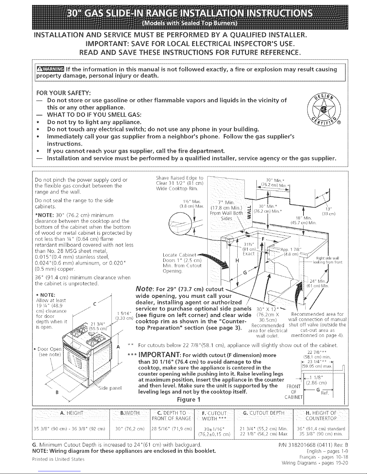
Do not pinch the power supply cord or
the flexible gas conduit between the
range and the wall
Do not seal the range to the side
cabinets
*NOTE: 30" (762 cm) minimum
clearance between the cooktop and the
bottom of the cabinet when the bottom
of wood or metal cabinet is protected by
not lessthan Y4" (064 cm) flame
retardant mi[Iboard covered with not Jess
than No_28 MSG sheet metal,
0015 "(0.4 ram) stainless steel,
0.024"(0.6 ram) aluminum, or 0020"
(0_5ram) copper_
36" (91 _4cm) minimum clearance when
the cabinet is unprotected
NOTE:
Allow at least
19 ¼" (48.9
cm) cbarance _
for door
depth when it
mopen.
Shave Raised Edge to
Clear 31 I/2" (81 cm)
Wide Cooktop Rim,
I Y2" Max
(3.8 cm) Max
Locate Cabinet_
Doors I" (2.5 cm)
Min. from Cutout
Opening
30" Mill*
I*
(17:8 cm Min.) _ 30" Min*
Fl'orn Wall Both _< (762 crn)Min*
Sides
18" Min.
(45.7 cm) Min
Right side wall
I from front
Note: For 29" (73.7 cm) cutout (6I cln)Min
wide opening, you must call your
dealer, installing agent or authorized
servker to purchase optional side panels :_0"x 12"
i 5/16" (see figure on left corner) and dear wide (76.2cm X Recommended area for
.SL33crN cooktop rim as shown in the "Counter- so.scm) wall connection of manual
Recommended shut off valve(outside the
/ top Preparation" section (see page 3}. area for electrical cut-out area as
wall oulet, mentionned on page 4)
Door Open
(see note)
panel
** For cutouts below 22 7/8"(581 cm), appliance will slightly show out of the cabinet.
22 7/8" **
*** IMPORTANT: For width cutout (F dimension) more (58.1 cm) rain.
than 30 1/16" (76.4 cm) to avoid damage to the i÷ 23 1/4.... -_1
(59 05 cIT_) t_ax
cooktop, make sure the appliance is centered in the _ _1
counter opening while pushing into it, Raise leveling legs kl ........ J
1 I/8
at maximum position, insert the appliance in the counter _ b_I_Ic/8_:',,, J I
and then level. Make sure the unit is supported by the FRONT [ _........ ' [ [
G
leveling legs and not by the cookto _ itself. OF _ Ref. 1 [
Figure 1 CABINET[ ' I
A HEIGHT B,WIDTH C, DEPTHTO F,CUTOUT H, HEIGHTOF [
FRC)NTOF RANGE WIDTH *** £OUNTERTOP
35 318" (90 cm - 36 318" (92 cm 30" (76,2 cm) 28 5/16" (71,9 cm (76,2±0,I30±1116"5cm 2122314"i/8.(55,2(56,2cm)cmMin,Max 36"35318"@1'4(90Cm)cm)Standardn'fin
G Minimum Cutout Depth is increased to 24"(61 cm) with backguard. P/N 318201668 (0411) Rev B
NOTE: Wiring diagram for these appliances are enclosed in this booklet. English - pages 1-9
Printed in United States Francais - pages 10-18
Wiring Diagrams- pages 19-20
Page 2
Important Notes to the Installer
1. Read all instructions contained in these installation
instructions before installing range.
2. Remove all packing material from the oven
compartments before connecting the gas and electrical
supply to the range.
3. Observe all governing codes and ordinances.
4. Be sure to leavethese instructions with the consumer.
Important Note to the Consumer
Keep these instructions with your owner's guide for future
reference.
IMPORTANT SAFETY
IN< NS
Installation of this range must conform with local (:odes
or, in the absence of local codes, with the National Fuel
Gas Code ANS! Z223. I/NFPA .54--latest edition.
This range has been design certified by CSA
International. As with any appliance using gas and
generating heat, there are certain safety precautions you
should follow. You will find them in the Use and Care
Guide, read it carefully.
• Be sure your range is installed and grounded
property by a qualified installer or service
technidan.
• This range must be electrically grounded in
accordance with local codes or, in their absence,
with the Nationa! Electrkal Code ANSI/NFPA No.
70--latest edition. SeeGrounding Instructions.
• Before installing the range in an area covered with
tinoleum or any other synthetic floor covering,
make sure the floor covering can withstand heat at
least 9O°F(32.2°C) above room temperature without
shrinking, warping or discoJoring. Do not install the
range over carpeting unlessyou place an insulating pad
or sheet of _/4"(0,6 cm) thick plywood between the
range and carpeting.
All ranges
can tip.
Injuryto
personscould
result.
Install anti-tip
device
packed with
range.
Toreduce
the risk of tipping of the
range, the range must be
secured by properly
installed anti-tip bracket
provided with the range.
To check if the bracket is
installed properly, grasp
the top rear edge of the
range and carefully tilt it
forward to make sure the
range is anchored.
Make sure the wall coverings around the range
can withstand the heat generated by the range.
• Do not obstruct the flow of combustion air at the
oven vent nor around the base or beneath the
lower front panel of the range. Avoid touching tile
vent openings or nearby surfaces as they may become
hot while the oven is in operation. This range requires
fresh air for proper burner combustion.
Never leave children alone or
unattended in the area where an appliance is in use.
As children grow, teach them the proper, safe use of all
appliances. Never leave the oven door open when the
range is unattended.
Stepping, leaning or sitting on the
doors or drawer of this range can result in serious
injuries and can also cause damage to the range.
• Do not store items of interest to children in the
cabinets above the range. Children could be seriously
burned climbing on the range to reach items.
• To eliminate the need to reach over the surface
burners, cabinet storage space above the burners
should be avoided.
• Adjust surface burner flame size so it does not
extend beyond the edge of the cooking utensil.
Excessive flame is hazardous.
• Do not use the oven as a storage space. This
creates a potentially hazardous situation.
• Never use your range for warming or heating the
room. Prolonged use of the range without adequate
ventilation can be dangerous.
• Do not store or use gasoline or other flammable
vapors and liquids near this or any other
appliance. Explosions or fires could result.
• In the event of an electrical power outage, the surface
burners can be lit manually. To light a surface burner,
hold a lit match to the burner head and slowly turn the
Surface Control knob to LITE. Use caution when
lighting surface burners manually.
Reset aH controls to the "off" position after using
a programmable timing operation.
FOR MODELS WITH SELF-CLEAN FEATURE:
Remove broiler pan, food and other utensils
before self-cleaning the oven. Wipe up excess
spillage. Follow the precleaning instructions in tile Use
and Care Guide.
• Unlike the standard gas range, THIS COOKTOP tS
NOT REMOVABLE. Do not attempt to remove the
cooktop.
Page 3
Cabinet Construction
To eliminate the risk of burns or fire by
reaching over heated surface units, do not have cabinet
storage space above the range. If there is cabinet
storage space above range, reduce the risk by installing
a range hood that projects horizontally a minimum of
5"(12.7 cm) beyond the bottom of the cabinet.
Countertop Preparation
The cooktop sides of the range fit over the cutout
edge of your countertop.
If you have a square finish (fiat) countertop, no
countertop preparation is required.
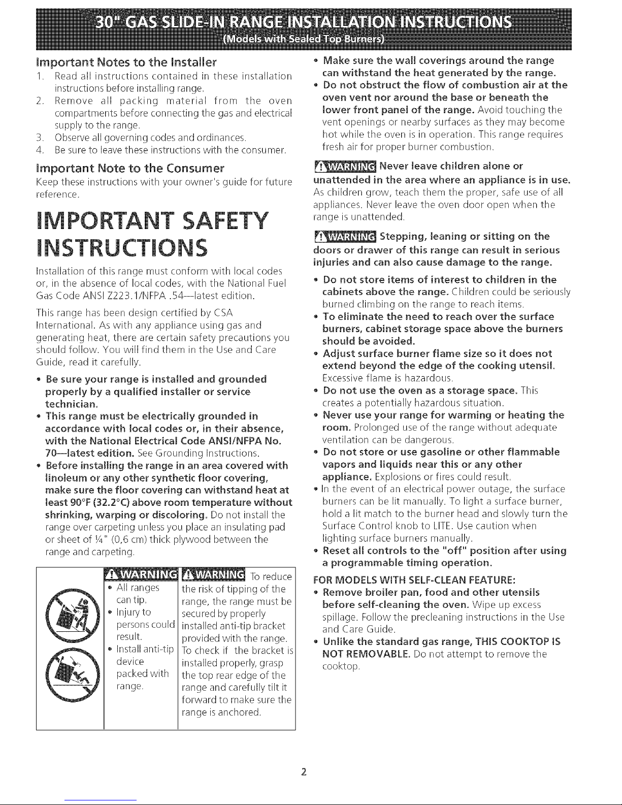
Formed front-edged countertops must have
molded edge shaved flat 3/4"(1.9 cm) from each
front corner of opening.
• Tile countertops
may need trim cut
back 3/4"(I .9 cm)
(I .9 cm) from
each front corner
and/or rounded
edge flattened.
314"
_._ cu!out
"B/wIdth 31 1/2
(81 cm)
__ Formed or tiled countertop
_3/4" " trimmed 3/4" (1.9cm)
(1.9 cm) back at from corners of
I countertop opening.
Figure 2
• tf the countertop opening width is greater than
the minimum cutout width, adjust the 3/4" (1.9
cm) dimension.
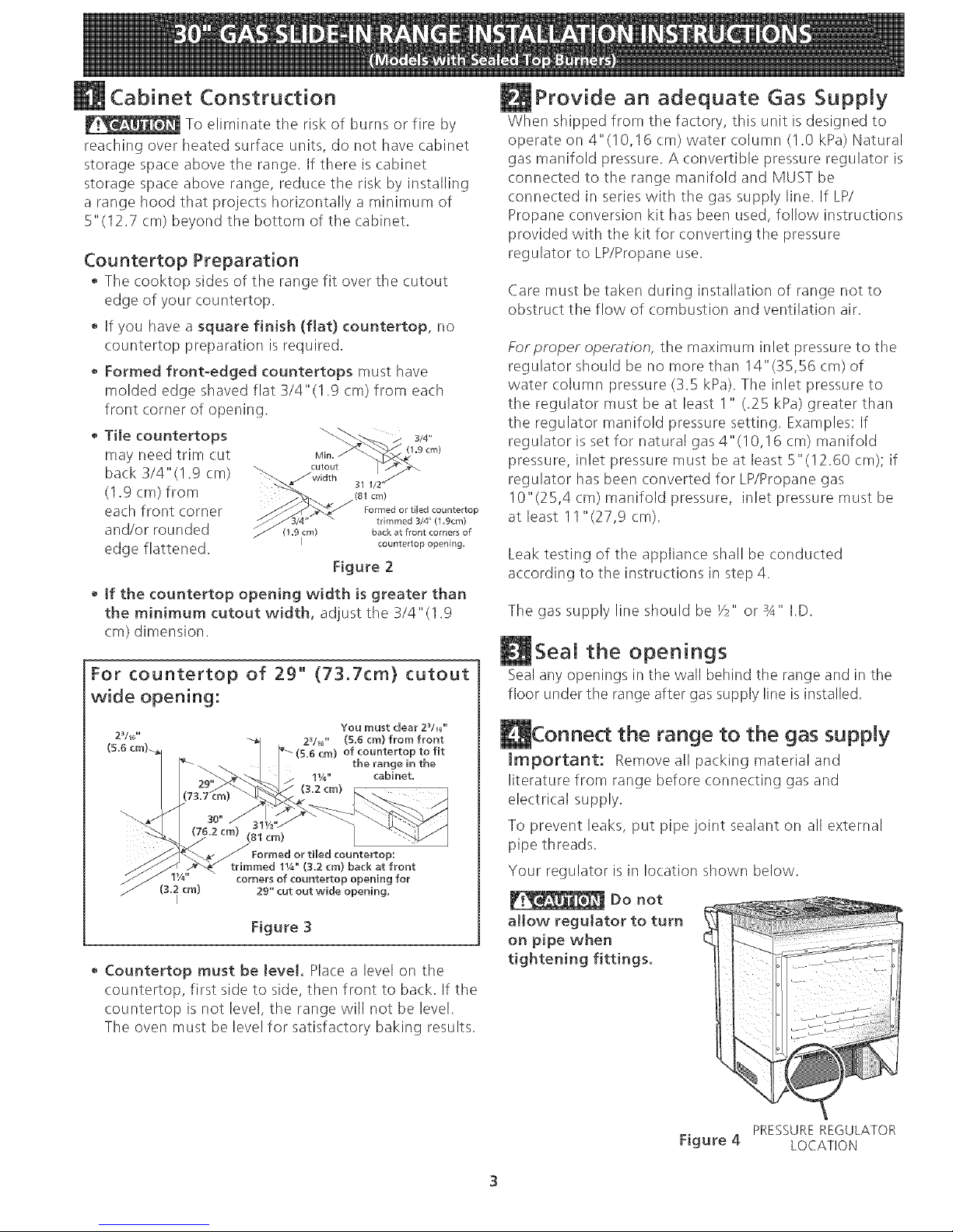
For countertop of 29" (73.7cm} cutout
wide opening:
You must clear 2V_J'
2_/_j ' (5.6 cm} from front
of countertop to fit
the range in the
11/4`` cabinet,
(3.2 cm)
p:
trimmed 1%" (3,2 cm) back at front
corners of countertop opening for
29" cut out wide opening,
Figure 3
• Countertop must be JeveL Place a level on the
countertop, first side to side, then front to back. If the
countertop is not level, the range will not be level.
The oven must be level for satisfactory baking results.
Provide an adequate Gas Supply
When shipped from the factory, this unit is designed to
operate on 4"(10,16 cm) water column (!.0 kPa) Natural
gas manifold pressure. A convertible pressure regulator is
connected to the range manifold and MUST be
connected in series with the gas supply line. If LP/
Propane conversion kit has been used, follow instructions
provided with the kit for converting the pressure
regulator to LP/Propane use.
Care must be taken during installation of range not to
obstruct the flow of combustion and ventilation air.
Forproper operation, the maximum inlet pressure to the
regulator should be no more than 14"(35,56 cm) of
water column pressure (3.5 kPa). The inlet pressure to
the regulator must be at least I " (.25 kPa) greater than
the regulator manifold pressure setting. Examples: If
regulator is set for natural gas 4" (I O,! 6 cm) manifold
pressure, inlet pressure must be at least 5"(12.60 cm); if
regulator has been converted for LP/Propane gas
10"(25,4 cm) manifold pressure, inlet pressure must be
at least 11 "(27,9 cm).
Leak testing of the appliance shall be conducted
according to the instructions in step 4.
The gas supply line should be _/2"or 3A" I.D.
Seal the openings
Seal any openings in the wall behind the range and in the
floor under the range after gas supply line isinstalled.
the range to the gas supply
_mportant: Remove all packing material and
literature from range before connecting gas and
electrical supply.
To prevent leaks, put pipe joint sealant on all external
pipe threads.
Your regulator is in location shown below.
Do not
allow regulator to turn
on pipe when
tightening fittings.
PRESSUREREGULATOR
Figure 4 LOCATION
Page 4
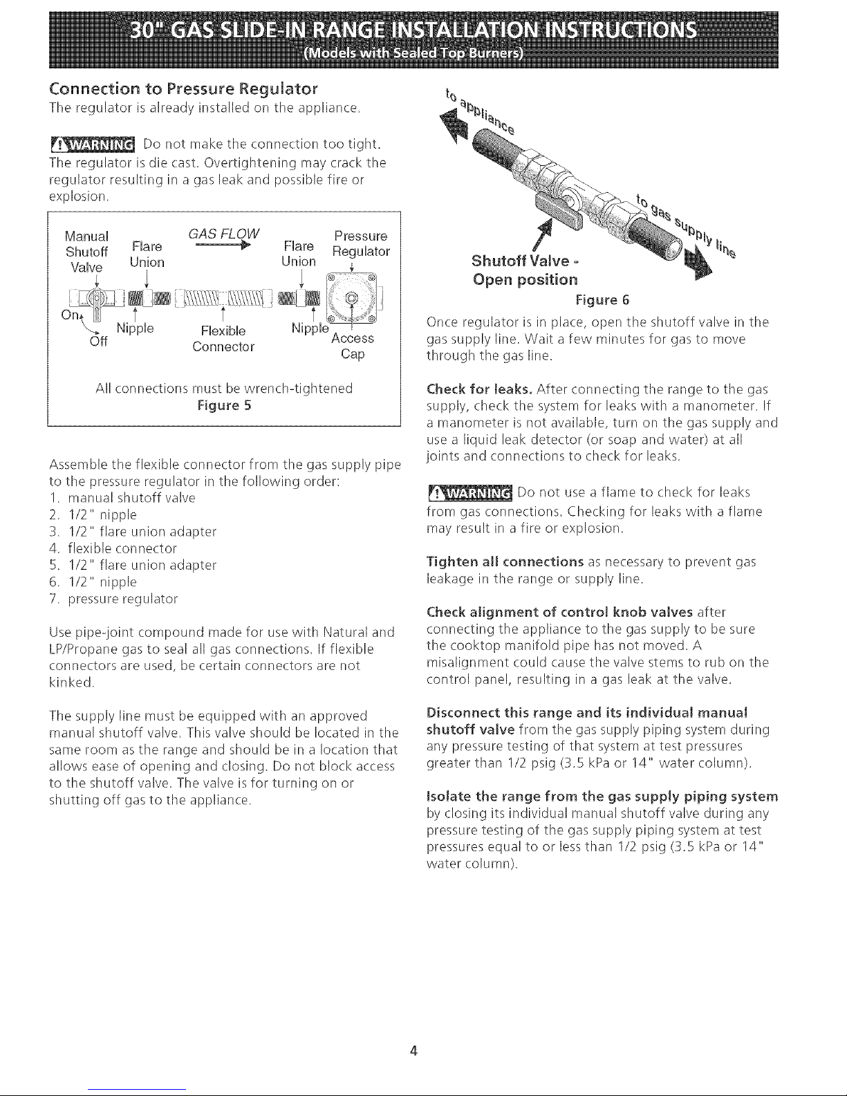
Connection to Pressure Regulator
The regulator is already installed on the appliance.
Do not make the connection too tight.
The regulator isdie cast. Overtightening may crack the
regulator resulting in a gas leak and possible fire or
explosion.
Manual GAS FLOW Pressure
Shutoff Flare _ Flare Regulator
Valve Union Union ¢
On, t t t
X._ Nipple Flexible NippleAccess
Off Connector
Cap
All connections must bewrench-tightened
Figure 5
Assemble the flexible connector from the gas supply pipe
to the pressure regulator in the following order:
1. manual shutoff valve
2. 1/2" nipple
3. 1/2" flare union adapter
4. flexible connector
5. 1/2" flare union adapter
6. 1/2" nipple
7. pressure regulator
Use pipe-joint compound made for use with Natural and
LP/Propane gas to seal all gas connections. If flexible
connectors are used, be certain connectors are not
kinked.
The supply line must be equipped with an approved
manual shutoff valve. This valve should be located in the
same room as the range and should be in a location that
allows ease of opening and closing. Do not block access
to the shutoff valve. Tile valve is for turning on or
shutting off gas to tile appliance.
li%
Shutoff Valve -
Open position
Figure 6
Once regulator is in place, open the shutoff valve in the
gas supply line, Wait a few minutes for gas to move
through the gas line.
Check for leaks. After connecting the range to the gas
supply, check the system for leaks with a manometer. If
a manometer is not available, turn on the gas supply and
use a liquid leak detector (or soap and water) at all
joints and connections to check for leaks.
Do not use a flame to check for leaks
from gas connections. Checking for leaks with a flame
may result in a fire or explosion.
Tighten a[[ connections as necessary to prevent gas
leakage in the range or supply line.
Check alignment of control knob valves after
connecting the appliance to the gas supply to be sure
the cooktop manifold pipe has not moved. A
misalignment could cause the valve stems to rub on the
control panel, resulting in a gas leak at the valve.
Disconnect this range and its individual manual
shutoff valve from the gas supply piping system during
any pressure testing of that system at test pressures
greater than 1/2 psig (3.5 kPa or 14" water column).
tsolate the range from the gas supply piping system
by closing its individual manual shutoff valve during any
pressure testing of the gas supply piping system at test
pressures equal to or lessthan 1/2 psig (3.5 kPa or 14"
water column).
Page 5
LPiPropane Gas Conversion
This appliance can be used with Natural gas or LP/
Propane gas. It is shipped from tile factory for use with
natural gas.
If you wish to convert your range for use with LP/Propane
gas, use the supplied fixed orifices located in a bag
containing the literature marked "FOR LP/PROPANEGAS
CONVERSION." Follow the instructions packaged with
the orifices for surface, oven and broil burners
conversion.
The conversion must be performed by a qualified service
technician in accordance with the manufacturer's
instructions and all local codes and requirements. Failure
to follow these instructions could result in serious injury
or property damage. The qualified agency performing
this work assumes responsibility for the conversion.
Failure to make the appropriate
conversion can result in serious personal injury and
property damage.
Electrical Requirements
120 volt, 60 Hertz, properly grounded dedicated circuit
protected by a 15 amp circuit breaker or time delay fuse.
Note: Not recommended to be installed with a Ground
Fault Interrupt (GFI).
Do not use an extension cord with this range.
Grounding Instructions
IMPORTANT Please read carefully.
For personal safety, this appliance must be properly
grounded.
The power cord of this appliance is equipped with a 3-
prong (grounding) plug which mates with a standard 3-
prong grounding wall receptacle (see Figure 7) to
minimize the possibility of electric shock hazard from the
appliance.
The wall receptacle and circuit should be checked by a
qualified electrician to make sure the receptacle is
properly grounded.
Preferred Method J
(I)_o not, under any /
Grounding type circumstances, cut,
wall receptaclE /q _ remove, or bypas_
the grounding /
......... _ Power supply cord with 3-
prong grounding plug.
Figure 7
Where a standard 2-prong wall receptacle is installed, it
is the personal responsibility and obligation of the
consumer to have it replaced by a properly grounded 3-
prong wall receptacle.
Do not, under any circumstances, cut or remove the
third (ground) prong from the power cord.
Disconnect electrical supply cord from
wall receptacle before servicing cooktop.
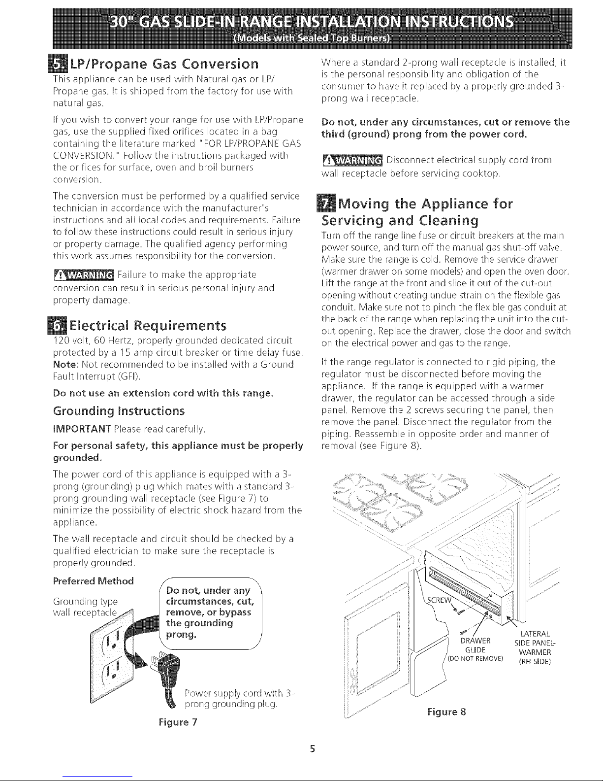
Moving the Appliance for
Servicing and Cleaning
Turn off the range line fuse or circuit breakers at the main
power source, and turn off tile manual gas shut-off valve.
Make sure the range is (:old. Remove tile service drawer
(warmer drawer on some models) and open the oven door.
Lift the range at the front and slide it out of the cut-out
opening without creating undue strain on the flexible gas
conduit. Make sure not to pinch tile flexible gas conduit at
the back of the range when replacing the unit into the cut-
out opening. Replace the drawer, close tile door and switch
on tile electrical power and gas to tile range.
If the range regulator isconnected to rigid piping, the
regulator must be disconnected before moving the
appliance. If the range is equipped with a warmer
drawer, the regulator (:an be accessed through a side
panel. Remove the 2 screws securing the panel, then
remove the panel. Disconnect the regulator from the
piping. Reassemble in opposite order and manner of
removal (see Figure 8).
LATERAL
DRAWER SIDE PANEL_
GLIDE WARMER
DO NOT REMOVE) (RH SIDE)
Figure 8
Page 6
Range JnstaJJation
Standard JnstaJJation
1. The range cooktop overlaps the countertop at the
sides and the range rests on the floor. The cooktop
is 31 I/2"(!,27 cm) (81 cm) wide.
2. Install base cabinets 30" (762 cm) apart. Make sure
they are level before attaching cooktop. Shave
raised countertop edge to clear 31 1/2 "(1,27 cm)
wide range top rim.
3. Install cabinet doors 31 " (78.7 cm) rain. apart so
they will not interfere with range door opening.
4. Cut out countertop exactly as shown on page 1.
5. A backguard kit can be ordered through your
qualified servicer.
6. To provide an optimum installation, the top surface
of the countertop must be level and flat (lie on the
same plane) around the 3 sidesthat are adjacent to
range cooktop. Proper adjustments to make the top
flat should be made or gaps between tile countertop
and the range cooktop may occur.
7. _ To reduce the risk of damaging your
appliance, do not handle or manipulate it by the
cooktop. Manipulate the appliance with (:are.
8. Position range in front of the cabinet opening.
9. Make sure that the cooktop which overhangs the
countertop clears the countertop. If necessary, raise
the unit by lowering tile leveling legs.
10.Leve! the range (seesection I0), The floor where the
range isto be installed must be level. Follow the
instructions under "Leveling the Range-Models
Equipped with Leveling Legs" (figure ! 5).
11. Adjust leveling legs so that the underside of the
cooktop issitting on the countertop.
12. Carefully screw in the back leveling leg until the
cooktop overhang slightly touches the countertop.
Tile cooktop must not support the unit.
13. Then carefully screw in the front two leveling legs
(similar to ! 1) until the cooktop overhang touches
slightly the countertop.
14.1fthe range isnot level, pull unit out and readjust
leveling legs, or make sure floor is level.
Installation For 29" Cutout Wide Opening
1. You must replace the actual side trims by new and
smaller side trims. These new side trims can be
ordered through your authorized servicer.
2. Follow instructions supplied with new side trims for
side trim replacement.
3. Check if the countertop is prepared for 29" cutout
wide opening in "Countertop Preparation" section.
4. Install range as in the "Standard installation"
section above.
Installation With Backguard
Tile cutout depth of (21 3/4" (55.2 cm) Min., 22 1/8"
(56.2 cm) Max.) needs to be increased to 24"(10,16 cm)
(61 cm) when installing a backguard.
Installation With Side Panels
Install cabinet doors 31 " (78.7 cm) rain. apart so as not
to interfere with range door opening.
NOTE
Side panel, Backguard and End Panel kits can be ordered
through your dealer or authorized servicer.
Check Operation
Refer to the Use and Care Guide packaged with the
range for operating instructions and for care and cleaning
of your range.
Remove all packaging from the oven before testing.
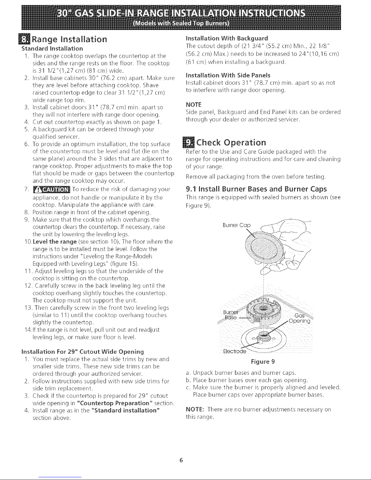
9.1 Install Burner Bases and Burner Caps
This range is equipped with sealed burners as shown (see
Figure 9).
Electrode _-
Figure 9
a. Unpack burner bases and burner caps.
b. Place burner bases over each gas opening.
c. Make sure the burner is properly aligned and leveled.
Place burner caps over appropriate burner bases.
NOTE: There are no burner adjustments necessary on
this range.
Page 7

9.2 Turn on Electrical Power and Open Main
Shutoff Gas Valve
9.3 Check the Igniters
Operation of electric igniters should be checked after
range and supply line connectors have been carefully
checked for leaks, and range has been connected to
electric power. To check for proper lighting:
a.Push in and turn a surface burner knob to the LITE
position. You will hear the igniter sparking.
b. The surface burner should light when gas is available
to the top burner. Each burner should light within four
(4) seconds after air has been purged from supply
lines. Visually check that burner has lit.
c. Once the burner lights, the control knob should be
rotated out of the LITEposition.
There are separate ignition devices for each burner. Try
each knob separately until all burner valves have been
checked.
9.4 Adjust the "LOW" Setting of Surface
Burner Valves (see Figure 10)
a.Push in and turn each control to LITEuntil burner
ignites.
b. Quickly turn knob to LOWESTPOSITION.
c. If burner goes out, readjust valve asfollows:
Reset control to OFF. Remove the surface burner
control knob, insert a thin-bladed screw driver into the
hollow valve stem and engage the slotted screw
inside. Flame size can be increased or decreased with
the turn of the screw. Adjust flame until you can
quickly turn knob from LITEto LOWEST POSITION
without extinguishing the flame. Flame should be as
small as possible without going out.
9.5 Operation of Oven Burners and Oven
Adjustments
9.5.1 Electric Ignition Burners
Operation of electric: igniters should be checked after
range and supply line connectors have been carefully
checked for leaks, and range has been connected to
electric power.
The oven burner is equipped with an electric control
system aswell asan electric:oven burner igniter. If your
model is equipped with a waist-high broil burner igniter, it
will also have an electric: burner igniter. These control
systems require no adjustment. When the oven is set to
operate, current will flow to the igniter. It will "glow"
similar to a light bulb. When the igniter has reached a
temperature sufficient to ignite gas, the electrically
controlled oven valve will open and flame will appear at
the oven burner. There is a time lapse from 30 to 60
seconds after thermostat isturned ON before the flame
appears at the oven burner. When the oven reachesthe
display setting, the glowing igniter will go off. The burner
flame will go "'out"' in 20 to 30 seconds after igniter goes
"OFF". To maintain any given oven temperature, this cycle
will continue aslong asthe display isset to operate.
After removing all packing materials and literature from
the oven;
a) Set the oven to BAKE at 300%. See Use & Care Guide
for operating instructions.
b) Within 60 seconds the oven burner should ignite. Check
for proper flame, and allow the burner to cycle once.
Resetcontrols to off.
c) If your model isequipped with a high-waist broiler, set
oven to broil. SeeUse& Care Guide for operating
instructions.
d) Within 60 seconds the broil burner should ignite. Check
for proper flame. Reset controls to off.
Page 8

9,5,2AirShutter-OvenBurner
//"
Lower
Oven Baffle
(removable) ""
///
_Waisi-H gh
Burner
Leveling the Range
Level the range and set cooktop height before
installation in the cut-out opening.
1. Install an oven rack in the center of the oven.
2. Place a level on the rack (seefigure 13). Take 2
readings with the level placed diagonally in one
direction and then the other. Levelthe range, if
necessary, by adjusting the 4 leg levelers with a
wrench (seefigure 15).
3. Taking care to not damage the countertop, slide range
into cut-out opening and double check for levelness.
Lower Oven Bottom
(removable)
Air Shutter
Figure ! 1
The approximate flame length of tile oven burner is 1
inch (distinct inner, blue flame).
To determine if the oven burner flame is proper,
remove tile oven bottom and burner baffle and set
the oven to bake at 300°F.
To remove the oven bottom, remove oven hold down
screws at rear of oven bottom. Pull up at rear,
disengage front of oven bottom from oven front
frame, and pull the oven bottom out of tile oven.
Remove burner baffle so that burner flame can be
observed.
If the flame is yellow, increase air shutter opening size
(see "2" in Figure 12.) If tile flame is a distinct blue,
reduce tile air shutter opening size.
To adjust loosen lock screw (see "3" in Figure 12),
reposition air shutter, and tighten lock screw. Replace
oven bottom.
/ Oven
/_@-- Burner
/ Tube
_ Orifice
Hood
Figure 12
9.5,3 Air Shutter-BroiJ Burner
The approximate flame length of the burner is ! inch
(distinct inner, blue flame). To determine if the broil burner
flame is proper, set the oven to broil. If flame is yellow,
in(tease air shutter opening size. (see "2" in Figure 12 ) If
tile entire flame is a distinct blue, reduce the air shutter
opening size. To adjust, loosen lock screw (see "3" in
Figure 12), reposition air shutter, and tighten lock screw.
@
iii
j_
/ f
Figure 13
When All Hookups are Compmete
Make sure all controls are left in the OFF position.
Make sure the flow of combustion and ventilation air to
the range is unobstructed.
Modem and Serial Number Location
The serial plate is located on the oven front frame
behind the oven door (some models or on the drawer
side frame (some models).
When ordering parts for or making inquiries about your
range, always be sure to include the model and serial
numbers and a lot number or letter from tile serial plate
on your range.
Your serial plate also tells you the rating of the burners,
the type of fuel and tile pressure the range was adjusted
for when it left the factory.
Before You Call for Service
Read the Before You Call Checklist and operating
instructions in your Use and Care Guide. It may save
you time and expense. The list includes common
occurrences that are not the result of defective
workmanship or materials in this appliance.
Refer to your Use & Care Guide.
Page 9

Anti-Tip Brackets JnstaJJation
To reduce the risk of tipping of the range,
the range must be secured to the floor by properly
installed anti-tip brackets and screws packed with the
range. Those parts are located in a plastic bag in the
oven. Failure to install the antPtip brackets will allow the
range to tip over if excessive weight is placed on an
open door or if a child climbs upon it. Serious injury
might result from spilled hot liquids or from the range
itself.
Follow the instructions below to install the antPtip
brackets.
If range is ever moved to a different location, the antPtip
brackets must also be moved and installed with the
range. To check for proper installation, see step 5.
Tools Required:
5/16" (0,79 cm) Nut driver or Flat Head Screwdriver
Adjustable Wrench
Electric Drill
3/16" (0,48 cm) Diameter Drill Bit
3/16" (0,48 cm) Diameter Masonry Drill Bit (if installing
in concrete)
Brackets attach to tile floor at the back of the range to
hold both rear leg levelers. When fastening to the floor,
be sure that screws do not penetrate electrical wiring or
plumbing. The screws provided will work in either wood
or concrete.
1. Unfold paper template and place it flat on the floor
with the back and side edges positioned exactly
where the back and sides of range will be located
when installed. (Use the diagram below to locate
brackets if template is not available.)
2. Mark on the floor the location of the 4 mounting
holes shown on the template. For easier installation,
3/16" (0.5 cm) diameter pilot holes !/2"(1,27 cm)
(1.3 cm) deep can be drilled into the floor.
3. Remove template and place brackets on floor with
turned up flange to the front. Line up holes in
brackets with marks on floor and attach with 4
screws provided. Brackets must be secured to solid
floor. If attaching to concrete floor, first drill 3/16"
(0.5 cm) dia. pilot holes using a masonry drill bit.
4. Level range if necessa% by adjusting 4 leg levelers
with wrench. (See Figure below.) A minimum
clearance of 1/8" (0.8 cm) is required between tile
bottom of the range and the rear leg levelers to
allow room for the antPtip brackets.
5. Slide range into place making sure rear legs are
trapped by ends of brackets. Range may need to be
shifted slightly to one side as it is being pushed back
to allow rear legs to align with brackets. You may
also grasp tile top rear edge of the range and
carefully attempt to tilt it forward to make sure
range is properly anchored.
Figure 14
Slide Back
Figure 15
Page 10

UN INSTALLATEUR QUALiF[I_ DOlT EFFECTUER L'[NSTALLAT[ON ET LE SERVICE
IMPORTANT: CONSERVEZ CES INSTRUCTIONS POUR LES INSPECTEURS LOCAUX.
MSEZ CES INSTRUCTIONS ET CONSERVEZ-LES POUR RI_FI_RENCES ULTI_RIEURES.
Si Jes instructions de ce manue[ ne sont pas suivies _ Ja [ettre, iJ pourrait en r6suJter un
incendie ou une expJosion susceptibJe de causer des dommages mat6rieJs, des bJessures ou m6me ta mort,
POUR VOTRE SECURITE:
-- N'entreposez et n'uti[isez pas d'essence ou d'autres produits inflammables a
proximit6 de cet apparei[ ou de tout autre appareiL
-- QUE FA[RE S[ VOUS DECELEZ UNE ODEUR DE GAZ:
• Ne tentez d°a[[umer aucun appareiL
® N'actionnez aucun interrupteur 6[ectrique; n'uti[isez aucun apparei[
t6[6phonique de ['6difice.
® imm6diatement avec votre fournisseur de gaz en vous servant du t6[6phone
d'un voisin. Suivez [es instructions que [e fournisseur vous donnera.
S'ii vous est impossible de rejoindre votre distributeur de gaz, communiquez avec ie service
d'incendie.
-- L'insta[[ation et ['entretien doivent 6tre effectu6s par un insta[[ateur qua[ifi6, un service
d'entretien ou de r6paration accr6dit6 ou [e distributeur de gaz.
Ne coincez pas le cordon d'alimentation ou leconduit
de gaz entre lemur et I'appareil
Nescellez pas I'appareil aux armoi/es lat#rales
*NOTE: Degagernent rninirnurn de 30" (762 cm) entre
la plaque de cuisson et la bas de I'amloire du haut
Iorsque le dessous de I'a/moire en bois ou en metal est
protege pal un celloderme retardateur de flammes d'un
rninirnum de Y4"(0.64 cm) recouvert d'une feuille de
metal MSG No 28, d'acier inoxydable d'un minimum
de 0015" (0.4 ram), daluminium de 0024" (06 ram)
ou de cuivre de 0020" (05 ram)
Degagement minirnum de :_6" @14 cm) [orsque
I'armoire n'est pas protegee
NOTE: Allouez C
au moins 19 X" .........
(489 cm) _......... 1 5116"
d'espace pour _. (3.33 cm)
permettre 21 3/4". i"
/-
Araser [e dessus du comptoir
au moins 31 I/2" (81 crn) de
largeur pour Fappareil.
I Y2"Max
(3 8 cm) Max
30" Min*
62 cm) Min/
18" Min
(45.7 cm) Min
I3"
(SScm)
Installez les portes de
I'armoire _ au
I" (2.5 crn) de
I'ouverture,
NOTE: Pour [es ouvertures de
(73.7 cm) de [argeur, vous devez appeler
un centre de service pour
panneaux lat6raux optionnels plus minces
pourinstaHerlacuisini_re, etvousdevez 30"X12"(762cm_
Mur de @oite
plac_
devanr
ili24"i_
(61 cm) Min
X 30.5 cm) - Ernpla- Po tion recornmand_e pour
pr6parer le comptoir tel que d6crJt a la cement recommand6 lebranchement de la Iigne
section "Pr6paration du dessus de pour ]aprise de de gaz (_ I'extedeur du
comptoir" (voir page 3). courant 61ectrique. d6coupage tel que
mentionneen page 13)
** Notez que pour les ouvertures de moins de 22 7/8" (58.1 22 7/8"**
cm), I'appareil depassera leg_rement vers I'avant du comptoir, (58.1 cm) rnin
1_23 114"*_1
***IMPORTANT: Pour une largeur de d6coupage (dimension F} plus grande que 30 1/15" (76.4 l (59.05 cnl) max.[ [-i
cm) et pour 6viter un bris de vitre, au moment d'inserer ["appareil darts le comptoir assurez= .......................................[
vous qu"i[ est bien centr6 darts ["ouverture. Levez les pattes de nivellement au maximum° DU (2.86 cm) , |
ins6rez l"apparei[ darts [e comptoir et ensuite nivelez=le. Assurez=vous que l"appareil est bien CABINET _ G Ref [
support6 par les pattes de nivellement et non par la surface vitrifi6e.
/ |
AI N_UTEIJR B.LARGELIR C. PRONFONDEUR X F. [ARGEURDE G, PROFONDEUR [ H. HAUTEUR DU
[ JL'AVANT DE L'APPAREILJ DECOUPAGE J DECOUPAGE J DESSUS DE COMPTOIF
35 3/8" (90 cm) - 36 S/S" (92 cm) 130" (76,2 cm)1 285/16"(71,gem) I 30_+I/16" I 213/4" (55,2 cm) Min. I :_6"(gl,4crn) norma[
1 1 [ (76,2 _+0,15 cm)[ 22 I/8" (56,2 cm) Max, _. 35 3/8" (90 cm)mir/
G Profondeur de decoupage minimum augment6e a 24" (61 cm) si un dosseret est install6. P/N 318201668 (0411) Rew
NOTE: Le schema de c&blage de ['appareH est indus au centre de ce feuillet. English - pages I@
Francais - pages I0-I8
Imprim6 aux Etats-Unis Sc6ma de cablage - pages 19-20
Page 11

Notes importantes a ['insta[[ateur
1. Lisez toutes les instructions contenues dans ce feuillet
avant d'installer la cuisiniere,
2. Enlevez tout le materiel d'emballage des compartiments
du four avant de connecter I'alimentation _] gaz et
electrique _] la cuisiniere.
3, Respectez tousles codes et reglements applicables.
4. N'oubliez pas de laisser ces instructions au
consommateur.
Note importante au consommateur
Conservez ces instructions avec le guide de I'utilisateur
pour reference ulterieure.
INSTRUCTIONS DE SECURITE
IMPORTANTES
Cette cuisiniere dolt _tre installee conformement aux
reglements Iocaux, ou en leur absence, aux normes
ANSI Z223.1/NFPA .54- derniere edition.
La conception de cette cuisiniere a ete approuvee par
CSA international, II faut prendre certaines precautions
d'usage Iors de I'utilisation de tout appareil fonctionnant
au gaz naturelou produisant de lachaleur, Vous
trouverez celles-ci dans votre Guide d'utilisateur, lisez-les
avec attention.
, Assurez-vous que votre cuisiniere est
correctement installee et raise & la terre par un
installateur ou un techniden d'entretien qualifie.
, Le circuit electrique de cette cuisiniere doit _tre
mis & la terre conform_ment au× reglements
Iocau×, ou en leur absence, au code electrique
ANSI/NFPA No,70-derniere edition. Voir les
instructions de mise _] la terre.
Avant d'installer la cuisiniere & un endroit
recouvert de linoleum ou de tout autre
couvreoplancher synthetique, assurez_vous que
celui_ci peut resister _ un minimum de 90°F
(32,2°C) de cha[eur au-dessus de la temperature
de [a piece sans se rapetisser, se deformer ou se
decolorer. N'insta!lez pas la cuisiniere sur un tapis, _]
moins de placer un tampon isolant ou une feuille de
contreplaque d'une epaisseur de Y4" (0.6 cm) entre la
cuisiniere et le tapis.
Toutes les
cuisinieres
peuvent
basculer.
• Des blessures
pourraient
survenir.
• Installer les
amafres qui
accompagnent
la cuisiniere.
Pour prevenir tout risque de
basculement de la cuisiniere,
cet appareil dolt _tre fixe
correctement au plancher _]
I'aide des amarres qui
I'accompagnent. Pour
verifier si les amarres sont
posees correctement, retirer
le tiroir de rangement et
s'assurer que les amarres
sont enclenchees.
Assurez-vous que [a tapisserie a proximite du
four peut resister a [a chaleur gen_ree par [a
cuisiniere.
Ne b[oquez pas la circulation d'air a I'orifice de
ventilation du four ni autour de la base ou sous
le panneau inferieur avant de [a cuisiniere, Evitez
de toucher les ouvertures de I'orifice de ventilation ou
les surfaces avoisinantes car elles risquent de devenir
chaudes Iorsque le four fonctionne. Les br01eurs ont
besoin d'air frais pour assurer une bonne combustion.
Ne laissez jamais les enfants
seuls ou sans surveillance pres d'un appareil en
fonctionnement. Apprenez-leur _] utiliser les appareils
electromenagers de faqon securitaire et appropriee. Ne
laissez jamais la porte du four ouverte Iorsque la
cuisiniere est sans surveillance.
Le fait de monter sur [es
portes ou [e tiroir de cette cuisiniere, de s'y
appuyer ou de s'y asseoir peut occasionner des
blessures graves, et endommager I'apparei[.
N'entreposez pas d'objets susceptibles
d'interesser [es enfants darts [es armoires situ_es
au-dessus de la cuisiniere. IIs risquent de se brOler
serieusement s'ils tentent de grimper sur I'appareil.
l_vitez de placer des armoires de rangement
au-dessus des brQleurs afin d'etiminer [es gestes
inutiles au-dessus de ceux-ci.
Reglez [a ftamme du brQleur pour qu'elle ne
depasse pas [e bord de ['ustensile uti[ise pour [a
cuisson. Une flamme excessive est dangereuse.
N'utilisez pas le four & des fins de rangement.
Ceci genere une situation eventue!lement dangereuse.
N'utilisez jamais votre cuisiniere pour rechauffer
ou chauffer [a piece, L'utilisation prolongee de la
cuisiniere sans une ventilation adequate peut s'averer
dangereuse.
Ne gardez pas de produits combustibles,
d'essence et d'autres produits inflammables
proximit_ de cet apparei[ ou de tout autre
apparei[. II pourrait en resulter des explosions ou un
incendie.
Lors d'une panne de courant electrique, les brOleurs de
surface peuvent _tre allumes manuellement; placez
une allumette allumee pres de la t_te du brOleur et
tournez lentement le bouton de commande de surface
la position LITE. Redoublez de pruden(e si vous
allumez un brOleur de surface manuellement.
Rep[acez toutes [es commandes & la position arr_t
_{off_ apres I'utilisation d'une fonction programmable
chronometree.
POUR MODELES AYANT UN FOUR AUTONETTOYANT:
En[evez [a [echefrite, [es aliments et [es autres
ustensi[es avant de faire un cycle autonettoyant
du four. Essuyez tousles renversements excessifs.
Suivez les instructions pour le pre nettoyage darts le
Guide de I'utilisateur.
11
Page 12

, Comme sur Jes cuisinieres standard a gaz, LA
TABLE DE CUISSON DE CET APPAREIL N'EST PAS
AMOVIBLE. Ne tentez pas de I'enlever.
Construction de ['armoire
Pour eliminer les risques de
br01ures ou de feu, en etendant le bras au-dessus des
surfaces de cuisson chaudes, evitez d'installer des
armoires au-dessus de ces dernieres. Si vous devez en
installer, il est possible de reduire le risque en pla_ant
une hotte pour cuisiniere qui excede horizontalement
d'un minimum de 5" (12.7 cm)la base de I'armoire.
Preparation du dessus de comptoir
o Les c6tes de la plaque de cuisson de la cuisiniere
s'ajustent au-dessus du rebord du decoupage du
dessus de comptoir.
Si vous avez un dessus de comptoir au fini carr_
(plat), aucune preparation n'est requise.
Les dessus de comptoir au rebord avant moule
doivent etre aplanis de :_A"(1.9 cm) _ chaque coin
avant de I'ouverture.
II est possible qu'il soit necessaire d'araser de :_A" (1.9
cm) les dessus de
comptoir en
mosa_'que
chaque coin
avant et/ou
d'aplanir le
rebord arrondi.
Si la [argeur du
Largeur de ¾"
decoupage (1.9 cm)
minimum
en mosai"que aplani de 3/4"
(1,91cm) (1,9 cm) aux rebords avant de
['ouverture de dessus de
Figure 2 comptoir,
dessus de comptoir est sup@rieure a [a [argeur
minimum requise, ajustez en consequence de 3/4"
(1.9 cm).
Pour [es d_coupages actue[ de 29"
(73.7 cm} de large: Enlevez 2 3/16"(5.ei era} d_:,
23/t6" mat_,riel_ Favant du
2 3/16" :m) comptoir pour permettre
6cm) Finstallation de ]acuisiniere.
1 114"
(3.2 cm)
(3.2 icm)
Figure 3
Dessus de cornptoir mouJ@ou en
rnosafque: aplanir 1¼" (32 crn)
aux rebords avant de chaque
c6te dans le cas d'une ouverture
de 29" (737 crn)
Le dessus de comptoir dolt &tre a niveau. Placez un
niveau sur le dessus de comptoir, d'abord de chaque
c6te, et ensuite du devant a I'arriere. Si le dessus de
comptoir n'est pas horizontal, la cuisiniere ne le sera
pas non plus. Le four doit etre a I'horizontale pour
obtenir des resultats de cuisson satisfaisants.
AJimentation en gaz - Installation
Cet appareil a ete conqu en usine pour fonctionner au
gaz naturel avec une pression d'admission de 4"(1 0,16
cm) de colonne d'eau (1.0 kpa). Un regulateur de
pression convertible est branche avec la rampe _ gaz de
la cuisiniere, et DOlT RESTER connecte en serie avec le
tuyau d'alimentation. Si un kit de conversion au gaz
propane est utilise, suivez les instructions de conversion
comprises dans le feuillet fourni pour convertir le
regulateur pour etre utilise avec le gaz propane.
Une attention particuliere doit etre prise Iors de
I'installation de !'appareil pour ne pas obstruer la prise
d'air pour la combustion et le conduit de ventilation de
I'appareil.
Pour un fonctionnement norma/, la pression interieure
maximale au regulateur ne dolt pas etre superieure
14"(35,56 cm) (3.5 kpa) de pression de colonne d'eau.
La pression d'admission au regulateur doit etre
superieure d'au moins un pouce (ou de .25 kpa) au
regulateur ajuste a la rampe a gaz. Pour le gaz naturel,
le regulateur etant ajuste ;] 4" (! 0,16 cm) de pression
(1.0 kpa), la pression d'admission dolt etre d'au moins 5
"(12,7 cm) de colonne d'eau (1.25 kpa). Pour le gaz
propane, le regulateur etant ajuste _ 10"(25,4 cm) de
pression (2.5 kpa), la pression d'admission doit etre d'au
moins 11 po (27,9 kpa).
La ligne d'alimentation dolt etre munie d'un robinet
d'arret approuve (voir Figure 6). Ce robinet dolt se
trouver darts la meme piece que la cuisiniere et _] un
endroit qui permette de I'ouvrir et de le fermer
facilement. Ne b!oquez pas I'acces au robinet d'arret. II
est destine _] ouvrir et _] fermer I'alimentation en gaz de
I'appareil.
Les tests pour verifier les fuites de gaz doivent etre faits
selon les instructions de I'etape 4.
La ligne de gaz doit etre de _/_" (1.3 cm) ou de :_A" (1.9
cm),
SceJJez Jes ouvertures
Scellez toutes les ouvertures dans lemur _] I'arriere de la
cuisiniere ainsi que celles darts le plancher sous I'appareil
une fois que la ligne de gaz est installee.
Branchez Je gaz & Ja cuisiniere
Important: Enlever tout le materiel d'emballage des
compartiments du four avant de brancher I'alimentation
gazet electrique _ la cuisiniere.
Afin de prevenir les fuites, utilisez des pates _]joints de
tuyauterie fabriquees pour utilisation avec gaz naturel et
propane.
12
Page 13

Le regulateur est situe tel
que montr6 ci-contre.
Ne
laissez pas le
regulateur glisser sur
le tuyau lots du
branchement.
Figure 4 Emplacement du
regulateur
Branchement du r_gulateur de pression
Le rSgulateur est installs a I'appareil.
Ne serrez pas trop les raccords. Le
rSgulateur est moulS sous pression. Un serrage excessif
pourrait le fissurer et provoquer une fuite de gaz
susceptible de causer un incendie ou une explosion.
Robinet Adapteur DEBIT Adapteur R6gutateur
d'arr6t de raccord DU GAZ de raccord de pression
manuel 6vas6 _ 6vas& ,,
Mamelon Flexible
Couvercle
Arr_,t6 Connector d'acces
Tousles branchements doivent 6tre serres
a I'aide d'une tie a ouverture fixe
Figure 5
Assemblez le connecteur flexible du conduit
d'alimentation en gaz au regulateur de pression darts
I'ordre qui suit
1. robinet d'arrSt manuel
2. F2" mamelon
3. Y2" adaptateur de raccord SvasS
4. connecteur flexible,
5. P_" adaptateur de raccord evasS
6. P_" mamelon
7. regulateur de pression.
Utilisez des pates a joints de tuyauterie fabriquees pour
utilisation avec gaz naturel et propane, pour sceller les
connexionsde gaz. Si desconnecteursflexiblessont
utilises, assurez-vous qu'ils ne sont pas tordus.
Figure 6
Une fois le regulateur en place, ouvrez le robinet de la
ligne d'alimentation en gaz. Attendez quelques minutes
pour que le gaz commence a circuler a travers la
canalisation pour le gaz.
Veillez _ ce quql n'y ait pas de fuites. Apres avoir
raccorde I'alimentation en gaz a la cuisiniere, a I'aide
d'un manometre verifiez si le systeme ne fuit pas. Si
vous ne disposez pas d'un manometre, ouvrez
I'alimentation en gaz et utilisez un liquide detecteur de
fuites sur tousles joints et les raccords.
N'utilisez pas de flamme nue
pour verifier les fuites de gaz. La detection des fuites
I'aide d'une flamme pourrait provoquer un incendie ou
une explosion.
Resserrez tousles raccords si necessaire, afin de
prevenir les fuites de gaz dans la plaque de cuisson ou le
tuyau d'alimentation.
Verifiez I'alignement des robinets, apres avoir relie
I'appareil a I'alimentation en gaz, afin de vous assurer
que la rampe du conduit de gaz n'a pas etS dSplacee.
Debranchez {a cuisiniere et fermez son robinet
d'alimentation en gaz !ors de toute verification de
pression du circuit d'alimentation de gaz a une pression
superieure a 1/2 Ib/po2 (3.5 kpa ou 14"(35,56 cm).
colonne d'eau).
Isolez la cuisiniere du r@seau d'alimentation en gaz
en fermant son robinet d'arr6t manuel, Iors de toute
verification de pression du circuit d'alimentation en gaz
a une pression inferieure ou egale a 1/2 Ib/po2 (3.5 kpa
ou 14 pc. colonne d'eau).
La ligne de gaz dolt Stre munie d'un robinet d'arr6t
manuel approuve. Ce robinet doit 6tre installs dans la
mSme piece que I'appareil et dolt 6tre facile d'acces.
Ne bloquez !'acces au robinet. Ce robinet permet
d'arrSter ou de permettre I'alimentation en gaz a la
cuisiniere.
13
Page 14

Conversion au gaz propane
Cet appareil fonctiorme au gaz nature! ou au gaz
propane. II est r6g16 en usine pour fonctionner au gaz
naturel,
Si vous desirez convertir votre cuisiniere au gaz propane,
servez-vous des orifices fixes fournis darts I'enveloppe
portant I'inscription <<POURCONVERSION AU GAZ
PROPANE>>, Suivez les instructions d'installation se
trouvant darts I'enveloppe,
Un insta!lateur qualifie dolt effectuer la conversion
conform_ment aux instructions du fabricant et ;] tousles
codes et reglements applicables. Sices instructions ne
sont pas suivies _sla lettre, il pourrait en resulter de
serieuses blessures corpore!les ou des dommages
materiels, L'entreprise d'installation qualifi_e qui
effectue ce travail assume la responsabilit_ de la
conversion.
_Si on n'effectue pas la conversion
correctement, il pourrait en resulter des blessures
corporelles et des dommages materiels.
Branches, le courant tectrique &
la cuisini re
Circuit de derivation de 120 volt, 60 Hertz, avec mise ;]
la terre appropri6e, proteg6 par un disjoncteur de 15
amperes ou un fusible temporis6.
N'utilisez pas de cordon de rallonge pour brancher
['appareil,
Instructions de raise & la terre
IMPORTANT Veuillez lire attentivement,
Pour votre propre securite, cet appareil dolt _tre
correctement mis a la terre.
Afin de reduire au minimum les risques de chocs
electriques, le cordon d'alimentation de cet appareil est
muni d'une fiche de contact tripolaire (raise ;] la terre)
enfichable darts une prise de courant murale tripolaire
standard avec raise _] la terre (figure 10),
II est conseille de faire verifier la prise de courant murale
et le circuit par un electricien qualifie, afin de s'assurer
que la prise de courant est correctement mise ;] la terre.
Methode j#r_feree
II est strictement
tper ou l
d"enlever la I
troisicme tige (raise
la terre) du cordon
Assurez-vous que
I'appareil est bien mis ;s
la terre avant de I'utiliser
Figure 7
Dans le cas o@ il n'y a qu'une prise de courant murale
bipolaire standard, il incombe au client de la remplacer
par une prise de courant murale tripolaire correctement
mise ;] la terre,
II est strictement interdit de couper ou d'enlever la
troisierae tige (rnise & la terre) du cordon
d'alimentation.
__ Debranchez le cordon d'alimentation
electrique de la prise de courant murale avant de
reparer ou de nettoyer la plaque de cuisson.
Deplacement de l'appareil en vue
d'en faire le service ou pour faire du
nettoyage
Coupez I'alimentation electrique de I'appareil a la boite
des fusibles ou des disjoncteurs et fermez le robinet
d'alimentation ;] gaz manuel, D_faites la connexion de
la tuyauterie rigide au regulateur, II n'est pas necessaire
de defaire cette connexion si un conduit flexible est
utilise, Assurez-vous que I'appareil est froid, Retirez le
tiroir de rangement, puis ouvrez la porte du four,
Soulevez la cuisiniere a I'avant et faites-la glisser hors de
son gite, tout en evitant de soumettre le conduit _] gaz
flexible ;] des contraintes excessives, Lorsque la
cuisiniere est replacee dans son gite, veillez _sne pas
coincer le conduit _] gaz flexible et le c_ble
d'alimentation electrique derriere I'appareil,
Reconnectez la tuyauterie rigide au r_gulateur (si
applicable) et verifier qu'il n'y a pas une fuite de gaz du
joint, Replacez le tiroir, fermez la porte et realimentez
I'appareil en gaz et en electricite (Figure 8).
Glissiere du
tiroir (ne pas
enlever}
Panneau
lat6ral de c6t_
(COt_ droit)
Figure 8
14
Page 15

lnstaliation de ia cuisiniere
Installation Standard
1. La table de cuisson chevauche de chaque c6te du dessus
du comptoir et la cuisiniere est assise sur le plancher, La
largeur de la table de cuisson est de 31Y2" (81 cm),
2. Les armoires sous le comptoir doivent @tredistantes de
30" (76,2 cm), Assurez-vous qu'elles sont d'aplomb et
de niveau avant d'y installer la cuisiniere. Araser le
rebord bombe ;] !'extremite avant du comptoir pour
obtenir un ajustement serre de 31_/2" (81 cm) entre les
bords ext@rieurs de la table de cuisson et le comptoir,
3. Distancez les portes des armoires de 31" (78,7 cm)
minimum afin qu'elles n'interferent pas avec I'ouverture
de la porte du four,
4, D@coupez le comptoir te! que montr@ _] la page 1,
5. Si un dosseret doit @tre install@, un n@cessairede service
(kit) peut @tre commande par I'intermediaire de votre
marchand.
6. Afin d'obtenir une installation maximale, les 3 c6t6s du
comptoir recevant I'appareil doivent 6tre plat et
niveau. Tousles ajustements adequats afin que le
comptoir soit plat doivent 6tre fair sinon des espaces
entre I'appareil et le comptoir peuvent se produire.
7. _ Pour eviter d'endommager
I'appareil, ne pas le saisir ou le manipuler par la vitre de
la surface de cuisson. Manipulezqe avec soin.
8. Placez I'appareil devant I'ouverture du comptoir.
9. Assurezwous que la surface de cuisson vitrifiee allant par
dessus le comptoir est bien plus haute que le comptoir. 5i
tel n'est pas le cas, levez I'appareil en baissant les pattes
de nivellement.
0.NiveJez [a cuisini_re (voir la section 10). Le plancher qui
supporte la cuisiniere dolt _tre de niveau (reportez-vous
la figure 15).
1.Ajustez les vis de nivellement pour que le dessous de la
table de cuisson repose au dessus du comptoir.
2.Doucement relevez les vis de nivellement arrDre afin que
la surface vitrifiee touche a peine le comptoir. La surface
vitrifiee ne dolt pas supporter I'appareil.
3.Finalement, relevez doucement les vis de nivellement
avant (comme en 11)jusqu'a ce que la surface vitri%e
touche a peine le comptoir.
14. Si la cuisiniere n'est plus de niveau, tirez-la hors du
decoupage et reajustez les vis de nivellement ou
assurez-vous que le plancher est bien au niveau.
Installation pour d_coupages de 29" (73.7 cm).
1. Vous devez enlever les moulures laterales actuelles par de
nouvelles moulures plus petites. Vous pouvez commander
ces moulures en appelant a un centre de service.
2. Installez vos nouvelles moulures a la place des moulu-
res actuelles, en suivant les instructions fournies avec
les nouvelles moulures.
3. Assurez-vous que le degagement du comptoir est
prepare pour les decoupages de 29" (73.7 cm) de
large. Voir la section "Pr6paration du dessus de comp-
toir" en page 3.
4. Installez I'appareil dans I'armoire tel que decrit a la
section prec6dente.
Installation avec un dosseret
La profondeur du decoupage de 21 3/4" (55.2 cm)mini-
mum et 22 1/8" (56.2cm) maximum dolt _tre augmentee
24" (61 cm) Iorsqu'un dosseret est installe sur I'appareil.
Installation de panneaux [at_raux
Distancez les portes des armoires de 31 " (78.7 cm) mini-
mum afin qu'elles n'interferent pas avec I'ouverture de la
porte du four.
NOTE
Un dosseret, des panneaux lat6raux et des embouts
peuvent 6tre commandes par I'entremise de votre mar-
chand ou d'un centre de service autorise.
V rification du Fonctionnement
Referez-vous au Guide de I'utilisateur inclus avec la
cuisiniere pour les directives de fonctionnement et pour
I'entretien et le nettoyage de votre cuisiniere.
Enlevez tout le materiel d'emballage du four avant de
commencer les essais.
9.1 Mise en place des bases et des
couvercles de brOleurs
Cette cuisiniere est munie de br01eurs scelles comme il
est indique ci-dessous (figure 9).
Couverc[e
du br_]leur_
Orifice
Base du d'alimentation
br_leur
en gaz
J
Electrode
Figure 9
A, Deballez les bases de br01eur et les couvercles,
B. Placez les bases de br01eurs au-dessus de chaque
orifice d'alimentation,
C. Verifiez que le br01eur est correctement align_ et ;]
niveau, Placez le couvercle sur la base de br01eur
appropriee,
NOTE : Aucun reglage de br01eur n'est necessaire dans
ce genre de cuisiniere.
15
Page 16

9.2 Branchez ['a[imentation en _[ectridt_
et ouvrez [e robinet prindpa[
d'alimentation en gaz
9.3 V_rifiez les allumeurs
II faut vOrifier le fonctionnement des allumeurs
electriques apres que la cuisiniere et les raccords du
tuyau d'alimentation aient ete eux-memes verifies
relativement aux fuites et que la cuisiniere ait ete
branchee a la prise de courant,
Pour verifier si I'allumage est adequat :
a. Appuyez sur le bouton de commande d'un brQleur de
surface et tournez-le _ la position <<LITE>>,Vous
entendrez les etincelles de I'allumeur electrique qui
allume le brQleur,
b. Le brQleur de surface dolt s'a!lumer Iorsque le gaz est
disponible au brQleur superieur, En fonctionnement
normal, chaque brQleur dolt s'a!lumer dans un delai
de quatre (4) secondes apres que Fair ait ete purge
des canalisations d'alimentation. Regardez si le
brQleur est allume,
c. Une fois le brQleur allume, le bouton de commande
dolt etre tourne _] une autre position que LITE,
II existe des dispositifs d'a!lumage separes pour chaque
brC]leur. Essayez chaque bouton separement jusqu'_] ce
que tousles robinets de br01eur aient ete verifies.
9.4 R_glez la position LOW des robinets
des br_leurs de surface (volt Figure 10)
1. Appuyez sur chaque commande et tournez-les a LITE
jusqu'a ce que le br01eur s'allume.
2. Tournez rapidement le bouton _] la position la plus
basse (LOW),
3. Si le br01eur s'eteint, re ajustez le robinet comme suit
: Remettez le bouton de commande _]arret (OFF),
Enlevez le bouton de commande du brQleur de
surface, inserez un tournevis _]pointe droite fine darts
la tige creuse du robinet et inserez dans la tote de la
vis, La hauteur de la flamme peut etre augmentee ou
diminuee en tournant la vis, Ajustez la flamme
jusqu'a ce que vous puissiez tourner rapidement le
bouton de LITE _] la plus base position (LOW) sans
eteindre la flamme. Celle-ci devrait _tre aussi
minuscule que possible sans s'eteindre.
9.5 Fonctionnement et r glage des br leurs
du four.
9.5.1 grQleurs a allumage electrique
Le fonctionnement des alhmeurs electriques devrait etre
verifie apres que la cuisiniere et I'arrivee de gaz aient ete
verifiees minutieusement pour detecter les fuites et que la
cuisiniere ait ete branchee au reseau electrique.
Le brQleur du four est muni allumeur electrique ainsi que d'un
systeme de commande electrique, Si votre modele est muni
d'un brQleur de rotisserie _ alimentation par prise unique, il
aura egalement un allumeur electrique, Ces systemes de
commande ne necessitent aucun ajustement. Lorsque le
fourneau sera pr_t _] fonctionner, le courant parviendra _]
I'allumeur qui deviendra incandescent et Iorsqu'il aura atteint
la temperature d'ignition du gaz, la valve de commande du
four commandee electriquement s'ouvrira et une flamme
appara_tra au brQleur du fourneau. II y a un delai de 30 _ 60
secondes apres que le thermostat soit mis en position "ON"
et le moment que la flamme apparaisse au br01eur du
fourneau, Lorsque le four atteindra la temperature reglee au
cadran, I'allumeur s'eteindra, La flamme du brC]leur s'eteindra
entre 20 et 30 secondes apres que I'a!lumeur eut ete coupe,
Ce cycle continuera pour maintenir toute temperature reglee
jusqu'a ce que I'indicateur/cadran soit remis _] "OFF".
Apres avoir enleve tout materiau d'emballage et la
documentation du four,
Reglez le four pour cuire "BAKE" _]300"F, Voir le Guide
d'utilisation et d'entretien pour les directives d'operation,
b) Le brQleur du four devrait s'allumer en dedans de 60
secondes, Verifiez si la flamme est convenable et repetez
la procedure une autre fois et remettez le bouton de
commande a "OFF")
Si votre modele est muni d'un brQleur de rotisserie _]
alimentation par prise unique, reglez le fourneau
rotisserie "BROIL", Voir le Guide d' utilisation et d'entretien
pour les directives d'operation,
d) Le brQleur de la rotisserie devrait s'allumer en dedans de
60 secondes, Verifiez si la flamme est convenable et
remettez le bouton de commande _] "OFF".
Figure 10
16
Page 17

9.5.2 BrQieur
fourneau & dapet d'air
BrQieur de r6tisserie
(ModUles a auto=
Clapet a air nettoyage)
Fond du four
(D_montable)
La !ongueur approximative de la flamme du brOleur du
fourneau est 1" (25 mm) (centre de flamme bleu distinct).
Pour determiner si la flamme du brOleur du four est adequate,
enlevez le fond du four et I'enceinte du brOleur et reglez le
fourneau _ 300°F
Enlevez les vis de maintien _ I'arriere du fond du fourneau
pour pouvoir retirer le fond du fourneau. 5oulevez a I'arriere,
degagez le fond avant du cadre du four et retirez le fond du
fourneau hors de celui-ci. Enlevez I'enceinte du brOleur pour
voir la flamme. 5i la flamme est de couleur jaune, augmentez
I'ouverture du clapet d'air (voir "2" ;_ la figure 12). 5i la
flamme est bleue, r6duisez I'ouverture du clapet d'air.
Pour faire le r_glage, desserrez la vis de blocage ("3" ;_ la
figure 12), repositionnez le clapet d'air et serrez la vis de
b!ocage. Replacez le fond du fourneau.
Tuyau du
br_leur du
fourneau
(9
Capot d'orifke
Figure !2
9.5.3 BrQ[eur de [a r6tisserie & dapet d'air
La Iongueur approximative de la flamme du brOleur du
fourneau est 1" (25 mm) (centre de flamme bleu distinct).
Pour d6terminer si la flamme du br@leur de la r6tisserie est
adequate, reglez le fourneau _ "BROIL". 5i la flamme est de
couleur jaune, augmentez I'ouverture du clapet d'air (voir
"2" a la figure 12). 5i la flamme est bleue, reduisez
I'ouverture du clapet d'air. Pour faire le reglage, desserrez la
vis de b!ocage ("3" ;_la figure 12), repositionnez le clapet d'air
et serrez la vis de blocage.
Mise & niveau de [a cuisiniere
Mettez [a cuisiniere de niveau et ajustez [a hauteur
de [a table de cuisson avant de ['installer darts [e
decoupage du comptoir.
1. Insta!lez une grille au centre du four.
2. Deposez un niveau _ bulle sur la grille (voir la figure 13).
Prenez 2 lectures en pla_ant le niveau en diagonale dans
une direction, puis dans !'autre direction. 5i necessaire,
ajustez les 4 vis de nivellement _ !'aide d'une cle pour
niveler I'appareil (reportez-vous a la figure 15).
3. Glissez delicatement la cuisiniere, en faisant attention de
ne pas aNmer le dessus du comptoir, dans le d_coupage
du comptoir et verifiez si e!le est encore de niveau.
f
Figure 13
Lorsque tous [es raccords sont terminus
Verifiez que toutes les commandes sont en position d'arrCt
(OFF).
Assurez-vous que la circulation d'air de combustion et de
ventilation _ la cuisiniere n'est pas obstruee.
Emplacement du num_ro de module et de
s_rie
La plaque signaletique est situee sur le chassis avant du
four, derriere la porte du four (certains modeles) ou sur
le c6t_ du tiroir (certains modeles).
Lors d'une commande de pieces ou pour toute demande
de renseignements au sujet de votre cuisiniere,
assurez-vous de toujours inclure les numeros de modele
et de serie et un numero de lot ou une lettre de la
plaque signaletique de votre cuisiniere.
La plaque signaletique vous donne egalement la
capacite des brOleurs, le type de carburant et la pression
laquelle la cuisiniere a et_ regime au moment de
I'expedition.
Avant d'appeler [e service d'entretien
Revisez la liste de verifications preventives et les
instructions d'operation darts votre Guide de I'utilisateur.
Vous sauverez probablement du temps et de I'argent.
La liste contient les evenements ordinaires qui ne
resultent pas de defectuosites darts le materiel ou la
fabrication de cet appareil.
Referez-vous a votre Guide de I'utilisateur.
17
Page 18

instructions de s cudt importantes
Pour r_duire le risque de
basculement de la cuisiniere, protegez-la en installant les
vis et les supports anti-bascules fournis avec la cuisiniere.
IIs sont situes darts un sac de plastique dans le four, Si
vous n'installez pasces supports anti-bascules, la
cuisiniere risque de basculer si un poids excessif est place
sur une porte ouverte ou si un enfant y grimpe, Les
renversements de liquides chauds ou la cuisiniere peuvent
provoquer de serieuses blessures,
Suivez les instructions ci-dessous pour installer les
supports anti-bascules,
Si vous deplacez la cuisiniere pour I'insta!ler bun autre
endroit, vous devez egalement d6placer les supports
anti-bascules pour les installer avec la cuisiniere, Voyez
I'etape 5 pour verifier comment proceder a une
installation correcte.
Outils Requis :
Tourne ecrou de 5/16"(0,79 cm) ou tournevis _]tCte carree
Cle a molette
Perceuse electrique
Foret de 3/16"(0,48 cm) de diametre
Foret de maqonnerie de S/16"(0,48 cm) diametre (si
I'insta!lation se fait dans du beton)
Instructions d'installation des supports
antiobascules
Les supports anti-bascules se fixent au plancher, ;]
I'arriere de la cuisiniere, pour retenir les deux pieds
niveleurs, En les fixant au plancher, assurez-vous que les
vis ne p6netrent pas darts la plomberie ou le c?]blage
_lectrique, Les vis fournies fonctionneront aussi bien dans
du bois que darts du beton.
Extremit_ arriere de la
cuisini_re ou paroi ardere
i
i
pport anti-bascule
1. Depliez le gabarit de papier et placez-le ;] plat sur le
plancher, I'endos et les extremit6s des c6tes
exactement & I'endroit oO I'arriere et les c6tes de la
cuisiniere seront places !ors de I'installation (utilisez le
diagramme ci-dessous pour Iocaliser les supports
anti-bascules si le gabarit de papier n'est pas
disponible),
2. Tracez sur le plancher I'emplacement des 4 trous de
montage indiques sur le gabarit, Pour faciliter
I'installation, des trous pilotes d'un 1/2"(1,3 cm) de
profondeur et 3/16" (0,5 cm) de diametre peuvent Ctre
perces dans le plancher,
3. Enlevez le gabarit et placez les supports anti-bascules
sur le plancher, le rebord renverse vers I'avant,
Alignez les trous dans les supports anti-bascules avec
les trous traces sur le plancher et fixez avec les 4 vis
fournies, Les supports anti-bascules doivent Ctre fixes
sur un plancher solide, Si vous les fixez _ un plancher
en b_ton, percez d'abord des trous pilotes de 3/16"
(0,5 cm) de diametre & I'aide d'un foret ;] maqonnerie
de 3/16" (0.5 cm) diametre,
4. Mettez la cuisiniere a niveau au besoin, en I'ajustant
avec les 4 pieds niveleurs ;] I'aide d'une cle ;] molette
(voir Figure 9), Un degagement minimum de 1/8" (0,3
cm) est requis entre le bas de la cuisiniere et les pieds
niveleurs arrieres pour disposer de suffisamment
d'espace pour installer les supports anti-bascules,
5. Replacez la cuisiniere en la faisant glisser, en vous
assurant que les pieds arriere ont ete bien agrippes par
les extremites des supports anti-bascules, II est possible
que vous ayez ;] la d_placer I_gerement d'un c6t_ en
la repoussant vers I'arriere pour que les pieds arriere
s'alignent avec les supports anti-bascules, Agrippez le
dessus de I'extr_mite arriere de la cuisiniere et essayez
soigneusement de !'incliner vers I'avant pour vous
assurer que la cuisiniere est correctement ancree.
Giisser vers
I'arri_re
Figure 15
Figure 14
18
Page 19

BAKE VALVE N
VDLVULA BE HORNEAR
BAKE ION1 !ER {)ETEN{)ELJR DE CUf_S()N 'J 6
NCENL' D0 DE HORN AR
..... AL LUkIEUR CU} SOON I
ELECTRONIC O,/EN CO TROL v /4 I _F _ la
CONTROL ELECTRONIC0 DE HORNO _ __ L U L,£ /.
(}0NIR01E (C!RON (}BE i k_ | BRC_i[: ,liVe' /
c c \\ VA V A E ASAR _ x
Y UE LNULU UV GM I LL,_u
BROIL IGNITER (_
ENCEND I DO DE DBAR F -- -- q
ALLUNEUR GR LLAGE 4 #_
BE ' I
v 4 I _ _
v 4 !_ ,nr,,_Q _! ,\N nc oR
RkIOBIA/O MOTOR D VENT LABORi ERkIB A r'qO LJR V Nr I A UR
TE,P RATURE PROBE R !4 ,, R _4, ___/ ..R _ ._,_. _,, /4 .
SONDA D TEMPE_ATUN_/ i _ m. _ _-_ ,_ i
. i
i i ,,
BI /'<+ _41 ,. '4 _ W 14
(}VEN lAMP
BR 14 NC i 'J I OVEN LAMP S_71TC/ LUZ BE IIORtqo
Sw A O._ / LA!CH PIOIOR INTERRUPTDR DE LUZ DE ORNO LAbI>E FOUR
LATCH ROTOR "---_.
MOTOR DE CERROJO
n /4
L
R
R
N0 W/BKI4
BAKE IGNIFER
ENCENDiDO DE ilORNEAR
BAKE VALVE
VALVU[A [}E HORNE/\R
DE]ENDEUR DE CUiSSON
N L
W6 R 6
J\
BL/W 14
OVEN LAMP
LUZ DE IIORNO
LAMPE FOUR
BK 14 ,4 4
I NTERR JPTEUR VERRO J
_ 1827 i 9_'0u Rrv_ i',
19
Page 20

COOKTOP C RCJ]T/C]RCJITO DE PLANCi IA DE COCINAR/
CIRCUIT TRBiE CU SSON
I
i
10P Bb'/NtR IGNI rE_ _'_'(/
QUEMAr_)R I)E EN(END DO SLPERIOR
IIOUG _ I}" RI I UNAGI URLJI H JR
/
TOP BUR[_R IGNITER _3/
QJEMADDb_ D K/JEND I DO bJP R IOR
BOUG D' ALLJNACE _RU_EJR
_OP BUR_£4 GNI JER
rAJt NAt) )R t] NC_ND I)05JPtRI OR
BOtJGIE D'/ / UtRGE F_tJL ELJR
/, tO i/Ib
]GNI]ER MODU E BOAR©
CU_DRO P_ MODULO DE ENCENDIDO
I BLOC COb_ECTION ALLUb'-/f_
R 14
LO
i I I
R(_HF RE#R
I GN SW
INT ENC TRASERO
DERECHO
IN/ER Ai _LJM
/_RR[ERE DRO] r
14 R 14
_>
d 14 d 14
Nc> >>
WRRNING//\VISO/R\/ER1 SSEIqEN]
D]SCONNEC! P5WER BEFORE BERV]C]NG LJIq)r/
DESESNECTE LA ENERGIA ANTES DE REA [ZAR
EL HANTEN]H ENTO DEL ELECTRODOMEST I C5/
COUPE_ LE COU_ANr RW_,NI D'EFFECTUE_
I f_ RE _ARA i ION
d I 0
k[RES COLOR NO/NO DE COLOR DE A A BRE/NO CO LEUR DES FI 5
COLOR CODE/COD ) GOB/CODE COULEUR
E_K I B_ACK/!gEG _D/NO [R P P I XIK/ROSA/ROSE
/aL j BLUE/AZUL/BLEU PR RP-_/PUR_'_REO/;'OUR_R _
G I (]REE N/VERDE/VER r v v I OL T/V I OL TA/V I OL T
96L!TmN
LABEL ALL WIRES PR]C@ TO D]SCONNECT ON _/4:[\ SERV]C NG CONTROLS
_IR]N© ERROR C,_N CAUGE IMPROPER /\ND D#'NGERC>JS OPERATION
VEI;_]PY PI_©°EI< ©°EId_f ON AFTER SERVIC]_
AVISO:
ET O_TE FODOS LOS ,_LAMBRES ANTES DE D_SCONFCTAR P_R
REAL IZAR ET NANTEN]N[ENTO DE LOS CONTROLES ERROR DE
ALAMBR_JE PUEDE CAUSAR UN FUNC[ONAH ENTO ]bPORRE TO
Y PEL}GRDS9 VER)OUE S] EL FUNC ONAH ENTO ESTA
CORRECTO DESPUES GEL MANTEN MIENTO
El [)H lEA rHAOH F_L AVAN LE DEEYRAN I MENF DE PEUX (] UNE ERREUR DE
BRAN{ EMENI PEU CAUSER UNE OPER# _ ! ION DAI&E _EUSE VERIF IER LE DON
FON£T }ONNEMENT DE L 'APPARE] L &P, RES TOUTE REP#_RAT }ON
/_ ! BHE/WP ITE STRIPE//RAY_5 RZLJ B[ ANCA//STRIE 8_ El/BlaNC
5
4 i
5 i
• i
i4
i2
i8
i6
14
I
I
I
I
I
i25
i £0
150
150
s _/s [
3i/3
i CL1551 31 Z5
I 0L1251 51 Z5
] EXL 50 5S2 NOtE/NO A/NO E
I EKE 50 332i } .............................
I EXL 15 _ _ CR(JI :)_)WN ,_1 rl /All CONTROLS %/ TO 'OF "
12 2 I 250 i
OVEN DOOR CLOSED AND UNLOCKED
EL CRCUI O ES[A ILUSF_ADO CON FOODS LOS C)NTR(LES A OFF"
(ARROA()O) Pk_RTA DE HORNO ABIERFA Y M) CERRADA
LE SCHEMA ELECTRIQUE [ND_OLE QUE LES CONHANDES SONT
A "A_ET ¸' _JE LA PORTE EST FERV_E ET NON VERRD_ILLEE
I
/ 9 i 50 l _2t I (X I BW 1
3252
518271900 RE,/: A
P: 2
20
 Loading...