

Friendly Robotics Robomow RL 1000 Operating & Safety Manual

Operating & Safety Manual
RL1000 & Docking Station
www.friendlyrobotics.com
DOC0076A

2
EC Declaration of Conformity
1. F. Robotics Acquisitions, Hatzabar St., Industrial Zone, Pardesiya, Israel declares that the
machines described in item 2 conforms with the directives listed in items 3 & 4.
2. Product: 24 Volt Battery operated automatic lawn mower, models RL500, RL550, RL800 RL850
and RL1000*.
Serial number: see mark on the machine.
3. Tested by the British Standards Institute (BSI) to comply with The supply of Machine (Safety)
Regulation 1992 Essential Health and Safety Requirements relating to the design and construction
of machinery.
The following European standards were taken into consideration when testing the machine:
EN 292: Parts 1 and 2:1991, Safety of Machinery - Basic concepts, general principles for design.
EN 294: 1992, Safety of Machinery - Safety distances to prevent danger zones being reached by
the upper limbs.
EN 418:1992, Safety of Machinery - Emergency stop equipment, functional aspects - Principles for
design.
EN 60204: Part 1:1997, Safety of Machinery - Electrical equipment of machines - general
requirements.
EN 60335: Part 1:1994, Safety of household and similar electrical appliances.
In addition the following National standard and draft were taken into consideration when testing the
machine:
BS 3456: Part 2: Section 2.42: 1997, Safety of household and similar electrical appliances Section 2.42 Battery-operated lawnmowers.
PrEN 50338: 1999, Safety of household and similar electrical appliances –Particular requirements
for pedestrian controlled battery powered electrical lawnmowers.
Noise level testing was conducted to the requirements of: 79/113/EEC and 88/181/EEC.
Results are published by BSI in report number 282/4077203 dated 14 July 2000.
Marylands Avenue, Hemel Hempstead, Hertfordshire HP2 4SQ, UK.
4. Also tested by Hermon Laboratories to comply with The Electromagnetic compatibility directive
89/336/EEC. Results are published By Hermon Laboratories in report number Frienmc_EN.14123
dated 21 June 2000.
Rakevet Industry Zone, Binyamina, 30550, Israel.
5. Measured sound power level: 85 db.
6. Guaranteed sound power level: 90 db.
7. Technical documentation kept by Mr. Dedy Gur, QA director.
I hereby declare that the above product conforms to the requirements as specified above.
*The original RL500 was tested by BSI in 2000. All Friendly Robotics models currently sold were tested by
F.Robotics Acquisitions Ltd.
Issued at Shai Abramson – Senior VP R&D
Pardesiya, Israel

3
The products are manufactured by F. Robotics Acquisitions (Friendly Robotics).
© Friendly Robotics, 2005-A. All rights reserved. No part of this document may be photocopied,
reproduced, electronically or translated without the prior written consent of Friendly Robotics.
Product, product specifications and this document are subject to change without notice. All other
trademarks are property of their respective owners.
CE approved.
Welcome to the world of home robotics with the Friendly Robotics Robomow!
Thank you for purchasing our product. We know that you will enjoy the extra free time you will have while
using Robomow to mow your lawn. When set up and used properly, Robomow will operate safely on your
lawn and provide you with a quality of cut matched by a few mowers of any kind. You will be impressed
with your lawn’s appearance and best of all, Robomow did it for you.
IMPORTANT!
The following pages contain important safety and operating instructions.
Please read and follow all instructions in this manual. Carefully read and
review all safety instructions, warnings and cautions contained in this manual.
Failure to read and follow these instructions, warnings and cautionary statements
may result in severe injury or death to persons and pets or damage to personal property.

4
Table of Contents
Safety Warnings & Precautions ………………………………………….….……… 5
Safety Features …………………………………………………………….….…..…. 7
What’s in the Box ………………………………………………………………….... 10
Chapter 1 – Docking Station & Perimeter Wire Setup…………………….….….. 12
Chapter 2 – Preparing the Robomow
®
……………………………………………. 29
Chapter 3 – Manual & Automatic Operation…………………………………….…37
Chapter 4 – Setting the Weekly Program…………………………………………..43
Chapter 5 – Charging…………………………………………………………………47
Chapter 6 – Settings and Advanced Features……………………………….….…51
Chapter 7 – Text Messages and Troubleshooting……………………………..….59
Chapter 8 – Specifications……………………………………….…………………..66
Chapter 9 – Maintenance and Storage…………………………………………..…67
Chapter 10 – Accessories……………………………………………………….…...71

5
Safety Warnings & Precautions
Training and Instructions
1. Read this manual carefully before operating Robomow
. Be familiar with the controls and
the proper use of Robomow
and follow all safety and warning instructions.
2. Do not use Robomow
for any purpose other than for which it is intended.
3. Never allow children or people unfamiliar with these instructions to operate Robomower.
4. Never mow while people, especially children, or pets are nearby.
5. The user is responsible for accidents or hazards occurring to other people or their
property.
Preparation
6. Make sure to layout and install the perimeter wire according to the instructions.
7. While mowing using a manual controller always wear substantial footwear and long
trousers.
8. Periodically inspect the area mowed by Robomow
, and remove stones, sticks, wires,
bones and other objects. Objects struck by the blades may be thrown and cause severe
injuries to people.
9. Before using Robomow
, always remove the power pack and visually inspect the blades for
wear or damage. Replace any worn or damaged blades.
10. Only use accessories and attachments designed for this product.
Operation
11. When using the Manual Controller mow only in daylight or in a good artificial light.
12. Do not operate Robomow
using the manual controller when barefoot or wearing open
sandals. Always wear substantial footwear and long trousers.
13. Avoid operating Robomow
on wet grass. Do not use it in rain.
14. When using manual controller always be sure of your footing on slopes.
15. Do not operate the mower on slopes greater than 15 degrees or use it in manual operation
on slopes where a firm footing is not possible.
16. Keep all guards, shields, safety devices, and sensors in place. Repair or replace damaged
parts, including decals. Do not operate Robomow if any parts are damaged or worn.
17. Do not operate Robomow
if any safety feature or device is damaged or inoperable.
18. Do not attempt to disable or defeat any safety feature or device.
19. When using the manual controller always switch on the motor according to instructions
and with feet well away from the blades.
20. This machine has sharp rotating blades! Never operate the mower if unattended; keep
bystanders, children and pets away from mower when in operation.
21. Never allow anyone to ride or sit on mower.
22. Keep hands and feet away from the cutting blades and other moving parts.
23. Never pick up or carry this appliance while the motors are running.
24. Never attempt to service or adjust the mower while it is in operation.

6
25. Never raise the mower or attempt to inspect the blades while the mower is operating.
26. Always remove the power pack before lifting the mower or attempting any adjustments.
27. Do not start Robomow
operation in automatic mode outside the plot bounded by the
perimeter wire.
Docking Station
28. When programming the automatic departure times and days, insure these windows of
operation are programmed when children, pets and other bystanders are not on the lawn.
29. Do not use the Docking Station power supply with an extension cord.
30. Do not place metal objects in the area of the charging contacts on the Docking Station.
31. Do not place metal objects across the charging pins of the Robomow.
32. After removing the power pack from the mower always reset the current day and time.
Failure to do so may result in improper setting of the day and time and non-intentional
operation of the Robomow, which may cause sever bodily injuries.
33. Do not spray water directly into the docking area of the Docking Station or onto the
operating panel of the Docking Station.
Maintenance and storage
34. Maintain, service, and store Robomow
according to the instructions (refer to chapter 9).
35. Keep all nuts, bolts, and screws tight to assure safe condition of this appliance.
36. Replace worn or damaged parts for safety.
37. Use heavy gloves when inspecting or servicing the blades.
38. Use only the original equipment, power pack and power supply/charger with this mower.
Incorrect use may result in electric shock, overheating or leakage of corrosive liquid from
the battery.
39. The charger (power supply) is for indoor use only. Do not use in areas where moisture or
water is likely. It is required placing it in a sheltered place, dry location, which is well
ventilated and not exposed to direct sunlight.
40. Do not dispose of the battery pack in a fire and do not place used batteries in your
household trash. The battery must be collected, recycled, or disposed of in an
environmentally sound manner.
41. Do not open or mutilate the power pack. Released electrolyte is corrosive and may damage
the eyes or skin.
42. Wear eye protection and use gloves when installing the perimeter wire and driving the wire
stakes/pegs. Firmly drive all pegs in order to keep the wire from becoming a tripping
hazard.
43. Do not use the power supply/charger if the cord has damaged.
44. Transport - to safely move from or within the working area:
1. Use the Manual Controller to drive it from place to place (See section 2.4)
2. In case of different height level or stairs, remove the Power Pack from the mower and
carry the mower by the carrying handle (See Figure no. 2.1).
7
Safety Warnings & Precautions
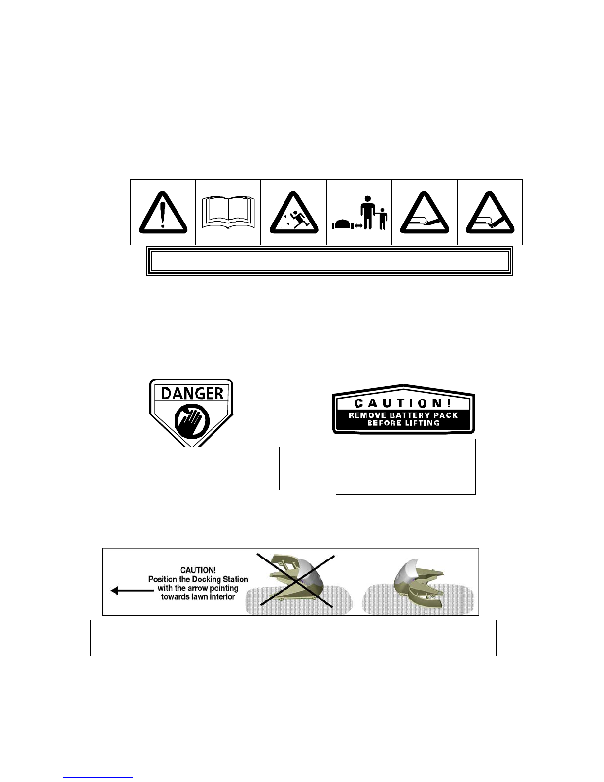
Warning Decal Definitions
1. WARNING-this is a dangerous power tool. Use care when operating and follow all safety
instructions and warnings.
2. Read the owner/operating manual carefully and follow all safety instructions.
3. Objects can be thrown from mower while operating, take caution.
4. Keep children, pets and bystanders away from mower.
5. Sharp rotating blades. Keep hands away and do not attempt to lift mower from this area.
6. Sharp rotating blades. Keep feet away.
.
The Docking Station fence must face towards the interior section of the lawn when
installed. Failure to do so may result in damage to property or persons.
1
2
5
DANGER! Sharp rotating blades.
Keep hands and feet away.
Serious injury can occur.
CAUTION! Remove
battery/power pack before
attempting to lift the
mower for any reason.

8
Robomow® - Safety Features
1. Child Guard / Safety Guard
This menu option offers a safety feature to help prevent children or others not familiar with the safe
operation of the mower to operate it freely.
2. Lift Sensor
There is a sensor located on the front caster wheel of the mower. In the event the front of the
mower is raised approximately 1-inch from its resting position on the ground during blade
operation, the blades will stop rotating immediately (< 1 second).
3. Sensor Equipped Bumpers
The front and rear bumpers are equipped with contacts that will activate when the mower strikes a
solid, fixed object when that object is at least 6-inches in vertical height from the supporting
surface of the mower. When the bumper sensor is activated, the mower will stop movement in that
direction and reverse itself away from the obstacle. In manual blade operation, bumper activation
will stop the rotation of the blades immediately (<1 second).
4. Emergency Stop Switch
Located on the top outer surface of the manual controller, red in color. Pressing this button at any
time during operation will stop all mower movement and stop the rotation of the blades
immediately (<1 second).
5. Automatic Mode Recognition
The Robomow is designed so that it cannot be operated in the manual mode while the Manual
Controller is in its pocket and it cannot operate in the automatic mode while the Manual Controller
is removed.
6. Two-Step Operator Presence Control
While in manual mode, it requires two independent finger actions in order to engage the mower
blades. Once engaged, the mower blade button must remain depressed to continue blade
operation. Once released, the two-step engagement process must be repeated.
7. Electronically Controlled Charging System
The Robomow is equipped with an on-board charge control system. This allows you to keep the
charger connected at all times, even after the battery is fully charged. The control system will
prevent an overcharge to the battery and keep it fully charged and maintained for the next use.
8. Sealed Power Pack
The power pack that operates the Robomow is completely sealed and will not leak any type of
fluids, regardless of position. In addition, the power pack contains a one-time-use fuse in the
event of a short-circuit or power malfunction.
9. Perimeter Switch and Perimeter Wire
The Robomow cannot operate without a perimeter wire installed and activated through the
Perimeter Switch. In the event the Perimeter Switch is turned off or otherwise fails to function, the
Robomow will stop operating. Likewise, should a break in the perimeter wire occur the Robomow
would again stop operation. A break in the perimeter wire prior to operation will prevent the
Robomow from operating. The Robomow can only operate within the boundary of the perimeter
wire.
10. Auto-Off Perimeter Switch
The auto-off feature of the perimeter switch shuts down the perimeter switch operation after
approximately 5 hours of continuous operation. This is typically 2 to 3 hours after which a fully
charged Power Pack will need to be re-charged. This helps to prevent unauthorized persons from
attempting to re-start the Robomow after it has completed its operation.
9
11. Over-Current Monitoring Protection
Each of the three blade motors and each of the two wheel drive motors are monitored
continuously during operation for any situation that may cause these motors to over-heat. In such
event, the Robomow will stop operation of at least that motor and possibly the mower itself and
indicate that the motor is cooling down. While unusual, this may happen when the mower is put in
grass that is severely overgrown; the underside of the mower is clogged from poor cleaning
maintenance; the mower has encountered an obstacle that is unable to activate the bumper
sensor preventing it from moving; or a problem landscape area has caused the mower to get stuck
and is preventing it from moving.
12. Automatic departure warning alert
When the mower is scheduled to depart the Docking Station automatically per a scheduled time, a
warning buzzer and the operating lamp will activate 5 minutes prior to departure. This is a warning
notification to clear and inspect the area.
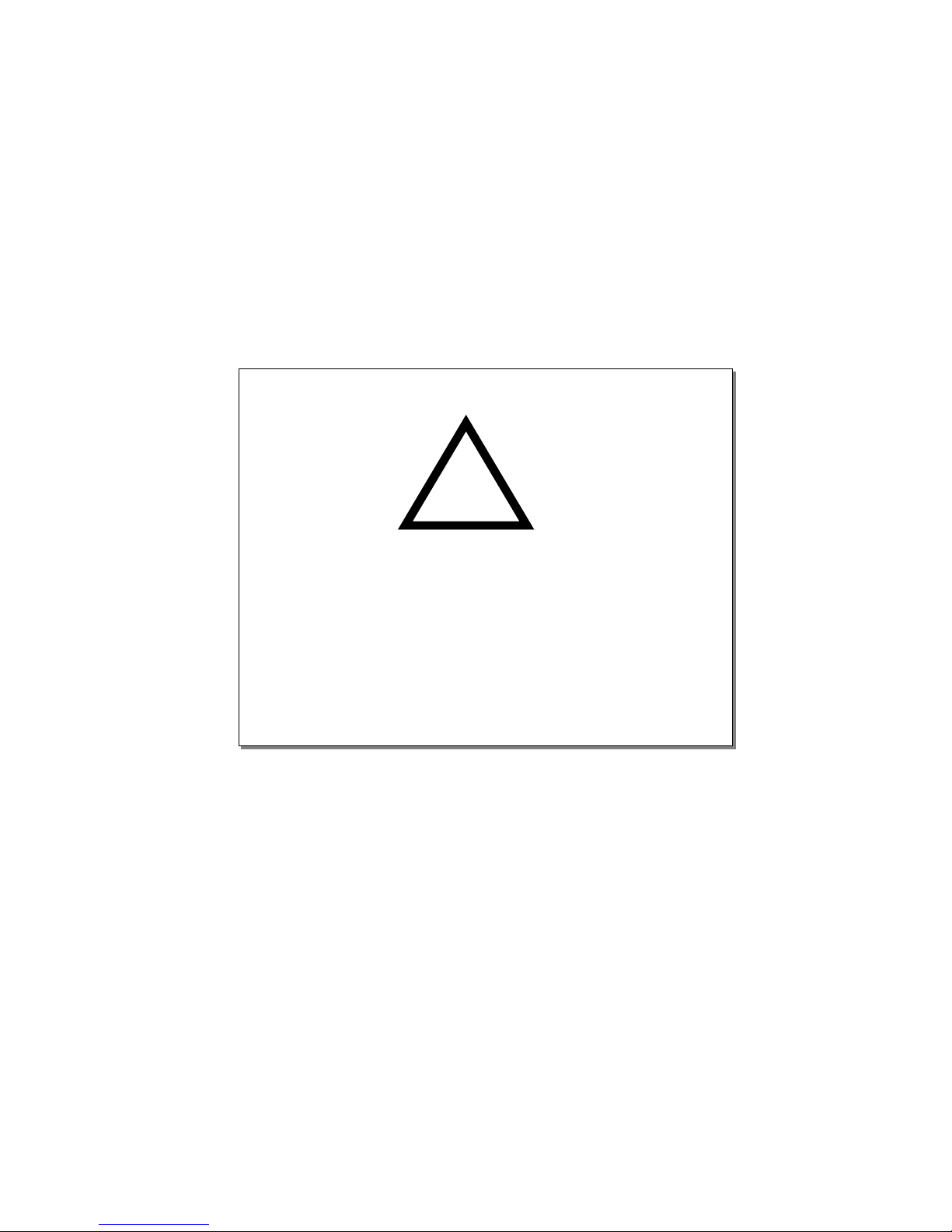
This warning symbol will be found at several
points throughout the pages of this manual.
It is intended to highlight an important safety,
warning or cautionary message.
Please pay particular attention to these
areas and be sure you fully understand
the message before proceeding.
WARNING!
!
10
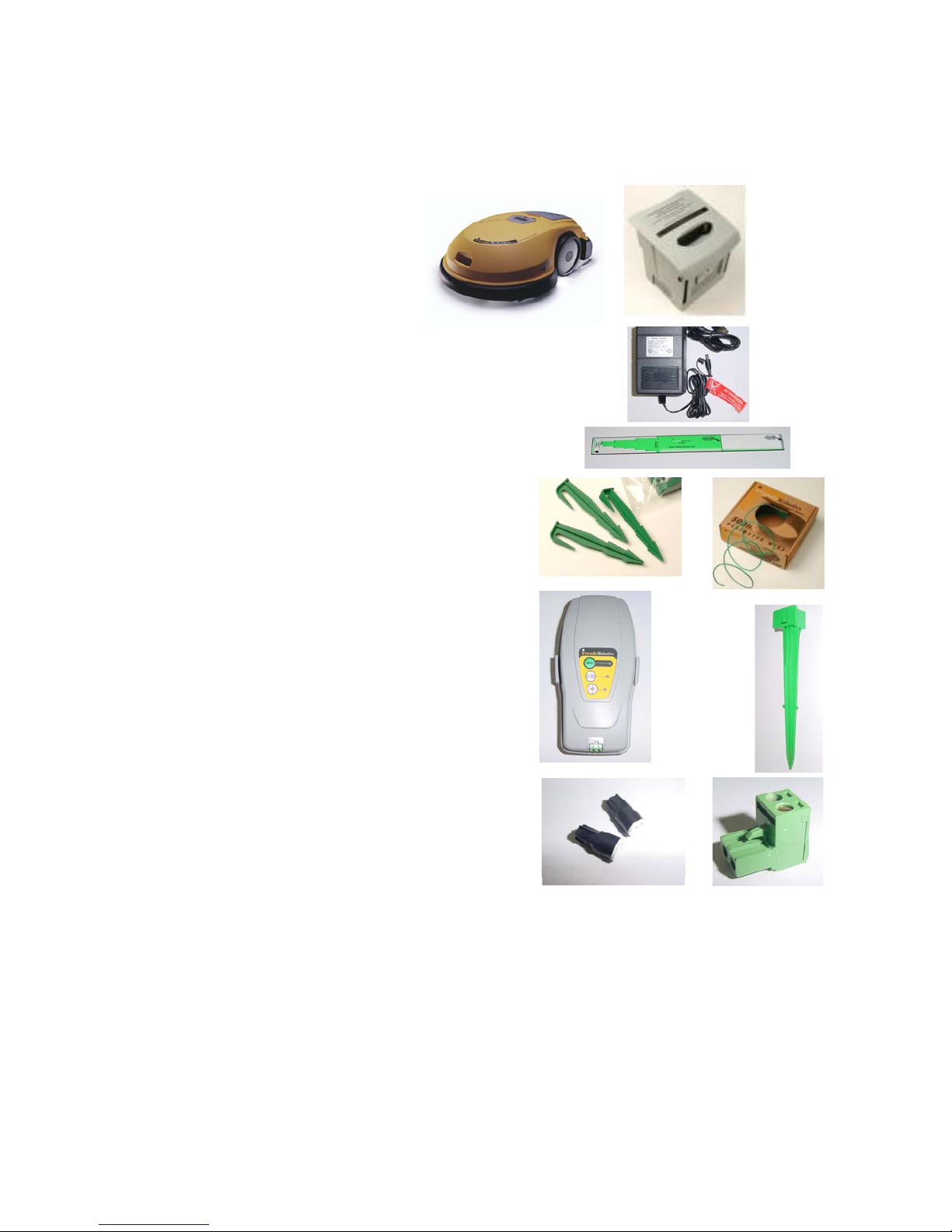
What’s in the Box
(Robomow®)
1. Robomow
®
2. Power Pack
3. Operating & Safety Manual
4. Standard charger
Used for recharging the Robomow
power pack. Indoor use only.
5.
RoboRuler
Used for setting the distance of the
perimeter wire from the lawn edge.
6.
Pegs
Used for securing the perimeter wire to
the ground around the lawn perimeter
and around obstacles.
7. Wire
Used to create a virtual wall for your
Robomow.
8. Perimeter Switch (& C-Cell Batteries)
Activates the perimeter wire, which
defines the area in which the
Robomow will operate.
9. Perimeter Switch Mounting Stake
Used for supporting the perimeter
switch in the lawn.
10.
Wire connectors
Used for splicing wires (as needed).
11. Plot connector
Used for connecting the completed
perimeter wire set-up to the perimeter
switch.
10
6
2
4
5
7
8
9
11
10
6
1
11
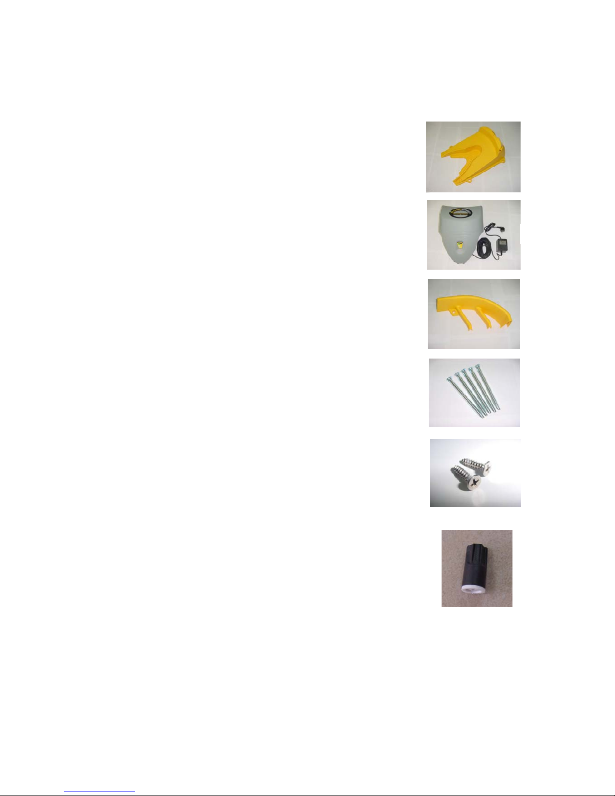
What’s in the Box
(Docking Station)
12. Base
Used for directing the Robomow to the
charging contacts.
13. Cover including the Perimeter Switch
& a Power Supply
Used for recharging the Robomow
Power Pack and activates the perimeter
wire, which defines the area in which
the Robomow will operate.
14. Docking Fence
Used for preventing the Robomow to
climb on the Docking Station during
operation.
15. Docking Stakes (x5)
Used for securing the Docking Station to
the ground.
16. Screws x2
Used for assembling the Docking
Station Cover to the Base.
17. Wire Connector
Used for splicing wire (as needed).
12
13
14
15
16
17
12
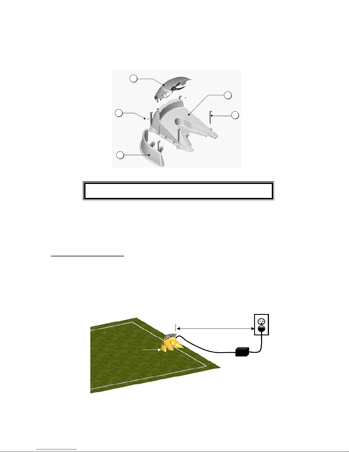
1
2
3
4
5
Base
Cover
Fence
Stake (x5)
Screw (x2)
11
22
33
44
55
Base
Cover
Fence
Stake (x5)
Screw (x2)
The Fence
should be
inside lawn
40 Volts
Maximum 50 ft (15m)
Power Supply
Receptacle
120 V
230 V
The Fence
should be
inside lawn
40 Volts
Maximum 50 ft (15m)
Power Supply
Receptacle
120 V
230 V
Chapter 1
Docking Station & Perimeter Wire Setup
Figure 1.1 Docking Station Assembly
1.1 Docking Station Zone
Before setting up the perimeter wire and Docking Station, it is best to examine your lawn and determine
the best location for the Docking Station. The Docking Station is a fully automatic solution suitable for one
area or zone, thus it is recommended to set it up in the largest area or zone. To mow other areas, simply
drive the Robomow to the area you want to mow and operate it in the automatic mode as explained in this
Manual. When this area is completed, drive the mower back to the station for re-charging.
Setup in Docking Zone
1.2 Docking Station Placement
There is a maximum distance of 50 feet (15 meters) from the receptacle to the Docking Station, see
figure 1.2. Do not use an extension cord to increase this distance. Should a distance of more than 50
feet (15 m) be required, refer to a locally qualified electrical professional to install a power source in
order to place power within the specified distance.
Position the Docking Station with the fence facing to the inside of the lawn. See figure 1.2.
Figure 1.2 – Distance From Power Receptacle
CAUTION! Refer to the specific safety instructions related with operation of
the Robomow with a Docking Station, as specified in the Safety chapter.
13
Greater than
8 feet (2.5m)
Note: The power supply is suitable for outdoor use, yet it is required placing it in a sheltered place, dry
location, which is well ventilated and not exposed to direct sunlight. It is recommended to place the
Docking Station as close as possible to a receptacle, roll the extra cable and store it near the power
supply. See paragraph 1.15 for further details on the cable.
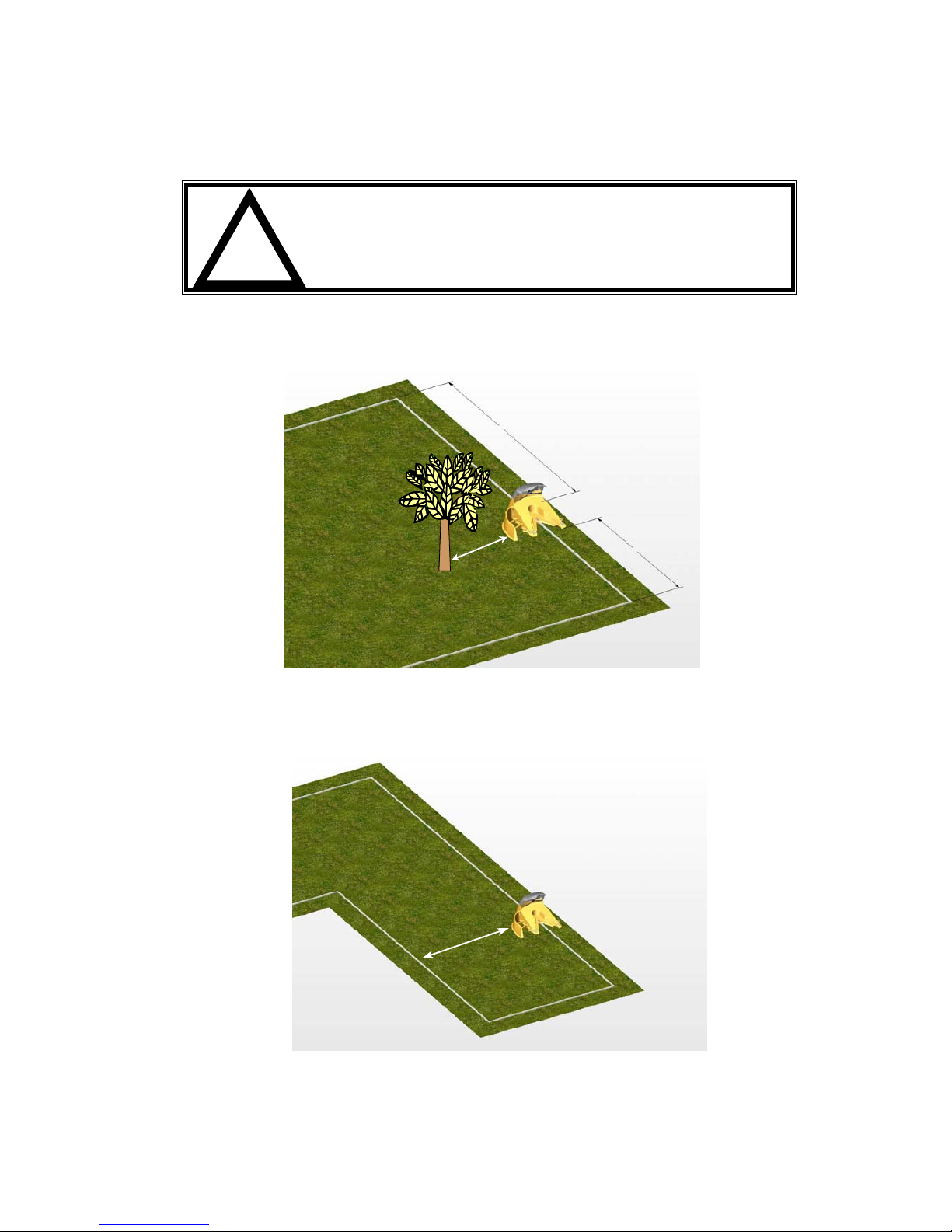
•
Place the Docking Station at minimum distances from corners of the perimeter as shown in figure 1.3
•
A minimum distance of 6 feet (2 meters) is required between the Docking Station fence and any
obstacle not excluded with the perimeter wire. See figure 1.3.
Figure 1.3 – Distance From Corners and Obstacles
•
A minimum distance of 8 feet (2.5 meters) is required between the Docking Station fence and the
perimeter wire. See figure 1.4.
Figure 1.4 – Distance From Perimeter Wire
CAUTION! Serious Injury Can Occur! When placing the power
cord leading to the Docking Station insure it is fastened securely
to the ground and does not present a tripping hazard.
Do not cross over surfaces such as sidewalks and driveways
where it cannot be fastened securely.
!
Greater than
4 feet (1.2m)
Greater than
8 feet
(
2.5m
)
Greater than
6 feet
(2m)
14
Greater than
8 feet (2.5m)
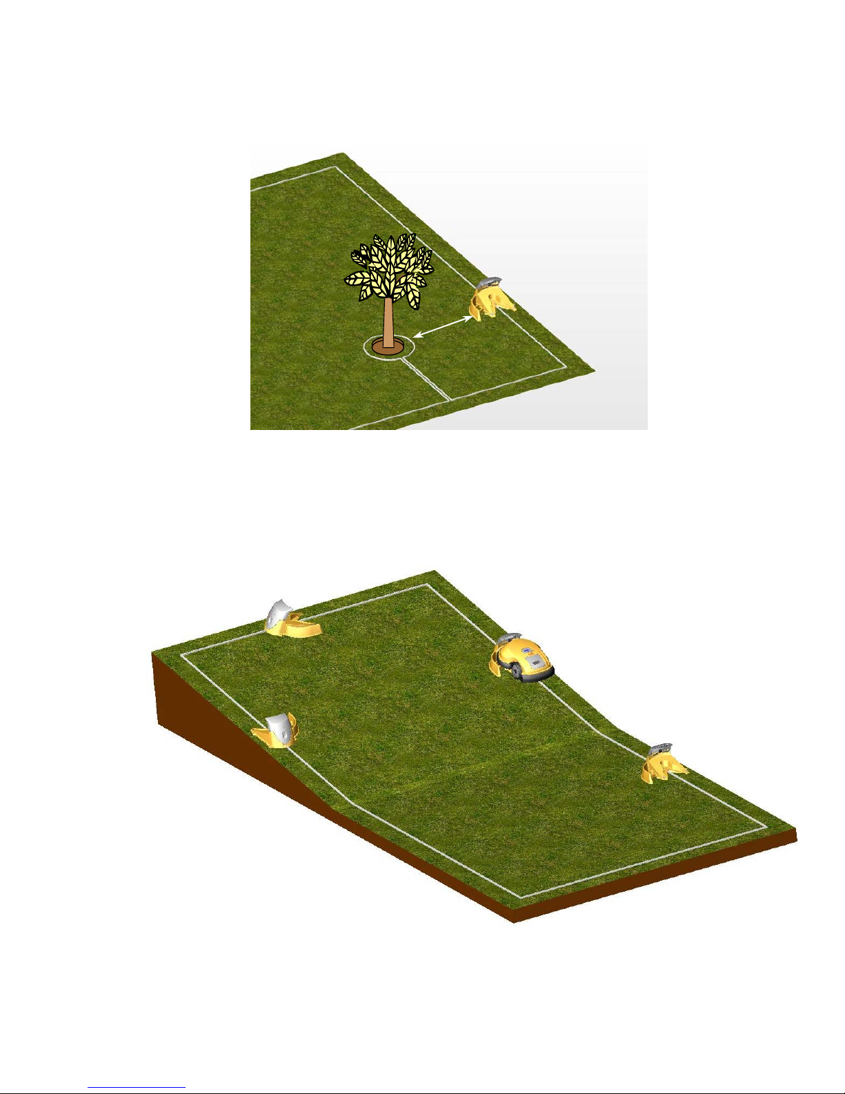
•
A minimum distance of 8 feet (2.5 meters) is required between the Docking Station fence and the
perimeter island. See figure 1.5.
Figure 1.5 – Distance From Perimeter Island
Place the Docking Station on level ground. Do not place the Docking Station on a slopping ground.
See figure 1.6. The area under and around the Docking Station MUST be flat to insure proper docking
of the mower into the Docking Station. Ensure both drive wheels are leveled with the Docking
Station base.
Figure 1.6 – Placing Docking Station on Level Ground
U
O
K
U
U
Relatively Level – OK
Slo
ping
– improper
15
•
The Robomow is impervious to water and rain, however it is recommended to place the Docking
Station away from sprinkler heads for maximum protection. See figure 1.7
Figure 1.7 – Avoid Placement Near Water Sprinklers
Now, knowing the location of the Docking Station, you can begin to setup the Perimeter Wire in the
docking zone.
1.3 Perimeter Wire Setup for Docking Zone and Non-Docking Zone
The perimeter wire setup in a docking and non-docking zone is identical in terms of placement and
fastening. In a non-docking zone, the perimeter wire ends will attach to the perimeter switch, where in the
docking zone they attach to the docking station board.
Puncture the plastic covering of the perimeter wire with your finger and feel around inside the center of the
wire spool for the end of the wire. Pull the wire end out of the plastic covering. The plastic covering is
designed as a dispenser for the wire, so do not remove the wire spool from the covering.
IMPORTANT: It is necessary to first read this chapter (Docking Station & Perimeter Wire Setup) before
starting to layout the Perimeter Wire, in order to be aware of all setup rules and instructions.
Starting at the location of the Perimeter Switch or the Docking Station, begin pulling the perimeter wire out
of the plastic covering as you walk along the area of the lawn you are setting up. Be sure to leave enough
wire at the beginning, where the Perimeter Switch or the Docking Station will be located. In the Docking
Station zone leave 8 inches/20cm – see figure 1.8. For Perimeter Switch (none-docking zone) leave no
less than 5 feet (1.5 m) of wire at the beginning of the setup.
After removing enough wire within a given section, use the RoboRuler (see section 1.4) to identify the
correct placement of the wire. Initially place a minimum number of pegs to fasten the wire down. You will
want to test the proper position of the wire for the edge mowing process and you may find some areas
where you will need to move the wire position slightly. See section 2.8 for details on testing. You can lightly
insert pegs into the ground by hand to hold the wire temporarily in place before driving the pegs to the
ground level with a hammer.
16
1.4 Using The RoboRuler
The Robomow includes a ruler style measurement stick called a RoboRuler that is used to help position
the perimeter wire along walls, fences, sidewalk, driveways, flower beds and other perimeter zones. There
are two basic measurements that are used on the RoboRuler. The shorter distance is used along
perimeter edges where the area outside the immediate perimeter (about 12 inches/30 cm) is free of
obstacles and is the same relative height as the perimeter edge. The longer distance is used along
perimeter edges where the area outside the immediate perimeter has obstacles or differences in the height
along the perimeter edge. See Figure 1.9.
Note: Use the short distance of the RoboRuler to set the wire position around the obstacle while creating a
Perimeter Island (See section 1.8).
1.5 Fastening The Wire To The Ground
It is not necessary to bury the perimeter wire, though you may do so if you wish, up to 3 inches (7.5 cm).
Small pegs or stakes are supplied with the Robomow and they are used to fasten and hold the perimeter
wire to the ground, below grass level. They resemble a small tent stake. When properly fastened to the
ground, the wire and pegs will soon disappear under the growth of new grass. The pegs simply hold the
wire in place at the ground level to allow for the grass to grow over it. Pegs should be driven at distances
between one another that will keep the wire down below the grass level and prevent it from becoming a
tripping hazard while in the process of being covered with grass growth. See Figure 1.10. Remember, you
want to test the wire setup for edge mowing before you fill in the additional pegs. See section 2.8 and 2.9
for details on testing.
Damage to the eye is possible. Use proper
eye protection and wear appropriate work
gloves when hammering the pegs.
Hard or dry ground may cause pegs to
break when driving them in. In extreme
cases, watering the lawn where the pegs
will be driven can be beneficial.
!
WARNING!
Figure 1.8 –
Starting The Perimeter Wire in a Docking Station zone
Short distance
Perimeter
wire
position
Area outside perimeter - same basic
level and free of obstacles.
Area outside perimeter - has a wall as
an obstacle.
Long distance
Perimeter
wire
position
Figure 1.9 – Using the RoboRuler
17
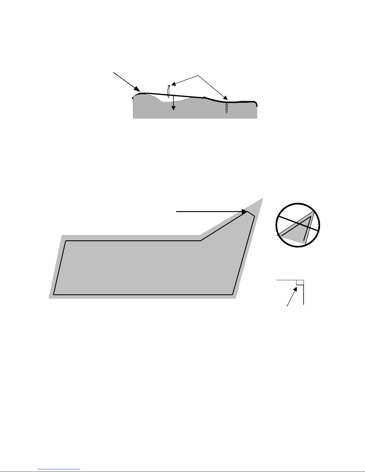
1.6 Corners & Sharp Turns
Care must be taken not to create a corner sharper than 90 degrees when setting up the perimeter wire. A
corner sharper than 90 degrees can cause the Robomow to lose track of the perimeter wire. In situations
where a corner may require a wire placement of less than a 90-degree angle, placement can be adjusted
using several angles to avoid this. See Figure 1.11.
1.7 Narrow Areas And Narrow Passes
There is a limitation to the width of an area the Robomow can effectively navigate through in order to move
into another larger, but attached area. A narrow pass is defined as an area that narrows down
substantially from the initial width and in which the Robomow must pass through in order to access and cut
other zones, an hourglass shape. The minimum distance for an effective narrow pass is 5.5 feet (1.7 m)
between perimeter wires. The larger a pass can be made, the better access Robomow will have between
the zones. This will greatly improve the effectiveness and efficiency of the mower. See Figure 1.14. For
an area that is narrow in width, but does not provide access to another section of the same zone, there is a
minimum working distance of 5.5 feet (1.7m). Figure 1.14.
Correct corner
setup, using several angles
to avoid an angle of less
than 90-de
g
rees
Incorrect corner
setup
Figure 1.11 – Proper Setup in Sharp Corners
Lawn area
90 degrees
Perimeter Wire
Add pegs in to pull the perimeter wire
down to the ground surface, below the
grass tips.
Figure 1.10 – Pegging the Perimeter Wire
18
1.8 Defining Obstacles-Perimeter Islands
Many obstacles can be left in the lawn without consideration to excluding them using the perimeter wire.
The basic rule of thumb is that the obstacle must be at least 6 inches (15 cm) high from the ground and the
obstacle must be relatively rigid. Good examples of these kinds of obstacles include many trees, phone
poles and power poles. When obstacles like this are encountered in the lawn, it is easiest to allow the
Robomow to bump into them, causing the bumper sensor to activate and assist in navigating around them.
Young, sapling aged trees are not good examples, as they are not very rigid. Other obstacles that are not
rigid and at least 6 inches high (15 cm) must be protected from the Robomow using the perimeter wire.
This is done as part of the setup process and is commonly referred to as a perimeter island. Good
examples of these types of obstacles are flowerbeds, islands, small trees and low bed edging.
The Robomow is designed to easily work in the lawn with both types of obstacles, however, for the most
gentle and silent operation, it is preferable to demarcate all fixed objects in and around the working area. If
you are unsure about a particular obstacle, it is best to exclude it with the perimeter wire. It will have no
effect on the efficiency of the mower and can later be removed if not needed.
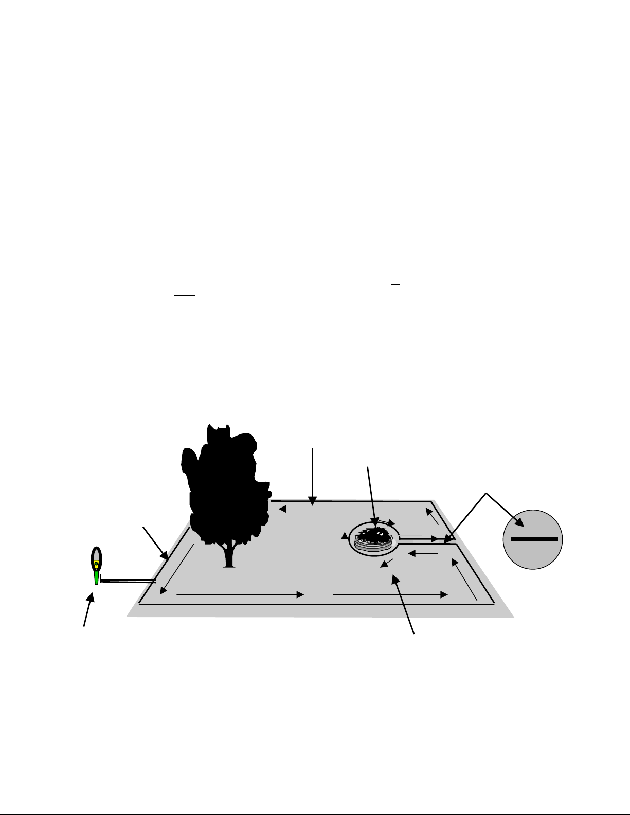
To create a perimeter island, take the wire from the perimeter section closest to the obstacle and peg the
wire around the obstacle, returning back to the same spot of the perimeter. There are two keys to setting
up the perimeter wire to exclude an obstacle; 1) place the wire going
to
the obstacle from the perimeter
and the wire going from
the obstacle to the perimeter adjacent to one another. This area is between the
obstacle and the normal lawn edge where the perimeter wire is set up; and 2) follow the direction of
installation when going to the interior of the lawn to exclude an obstacle. While the picture in figure 1.12
may appear to have the wires leading to and from the island set up with a space between them, this is for
illustration purposes only. A proper placement of these two wires is to have them touching one another,
but in no event should they be farther than 1/8 of an inch (3 mm) apart from one another. For the best
results, place both wires under the same peg when placing them in the lawn around obstacles. Placement
of the wires as described allows for the signal in the two wires to cancel, but only in the area where they
are installed adjacent to one another and touching. By canceling the signal in this section, the Robomow is
free to cross this area but will still recognize the signal of the perimeter island. See Figure 1.30.
Perimeter
wire
Flowerbed
While the picture shows two
wires separate, they should be
adjacent and no more than 1/8
inch (3 mm) from one another
Perimeter switch placed at least 3 feet
(0.9 m) from perimeter. Wires to
perimeter switch should be placed
adjacent, the same as wires leading to
an obstacle.
Direction of
set up
Figure 1.12 – Excluding Obstacles With the
Perimeter Wire
Direction of set up
followed around
obstacle
19
Large trees,
OK to be treated
as an obstacle
and not excluded
with the perimeter
wire. Be sure they
are at least 4 feet
(1.2m) from the
p
erimeter.
Zone one
Zone two
Width must be greater than
5.5 feet (1.7 m), measured from
perimeter wire to perimeter wire
3 feet (0.9m)
Distance greater than
5 feet (1.5 m)
Figure 1.14 – Two Zone Setup With One Docking Zone
Narrow passes should
be at least 5.5 feet
(1.7m) between wires
Closer than 4 feet (1.2 m)
to perimeter wire,
loop out
Trees large enough to allow
Robomow to bump into do not
require a perimeter wire around it
Small tree, must
exclude with perimeter
wire
Tree too close to
perimeter, less than 4
feet (1.2m), loop out with
perimeter wire
Minimum distance
between obstacle wire
and perimeter wire = 5
feet (1.5 m)
Greater than 3 feet
(0.9 m)
The Robomow can freely move across this section, but will still
recognize the perimeter island. By allowing this, multiple obstacles in a
given lawn will have little effect on free movement of the Robomow or
its’ efficiency.
Figure 1.13 – Perimeter Wire Setup Distances for Obstacles
Docking Station
20
Perimeter
Switch
Docking
Station
Driveway
House and
garage
Dock Zone
Back yard
Zone B
Front yard
Plot
Connector
Zone C
Side yard
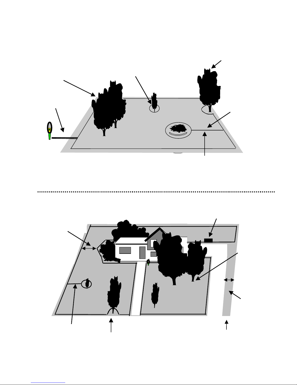
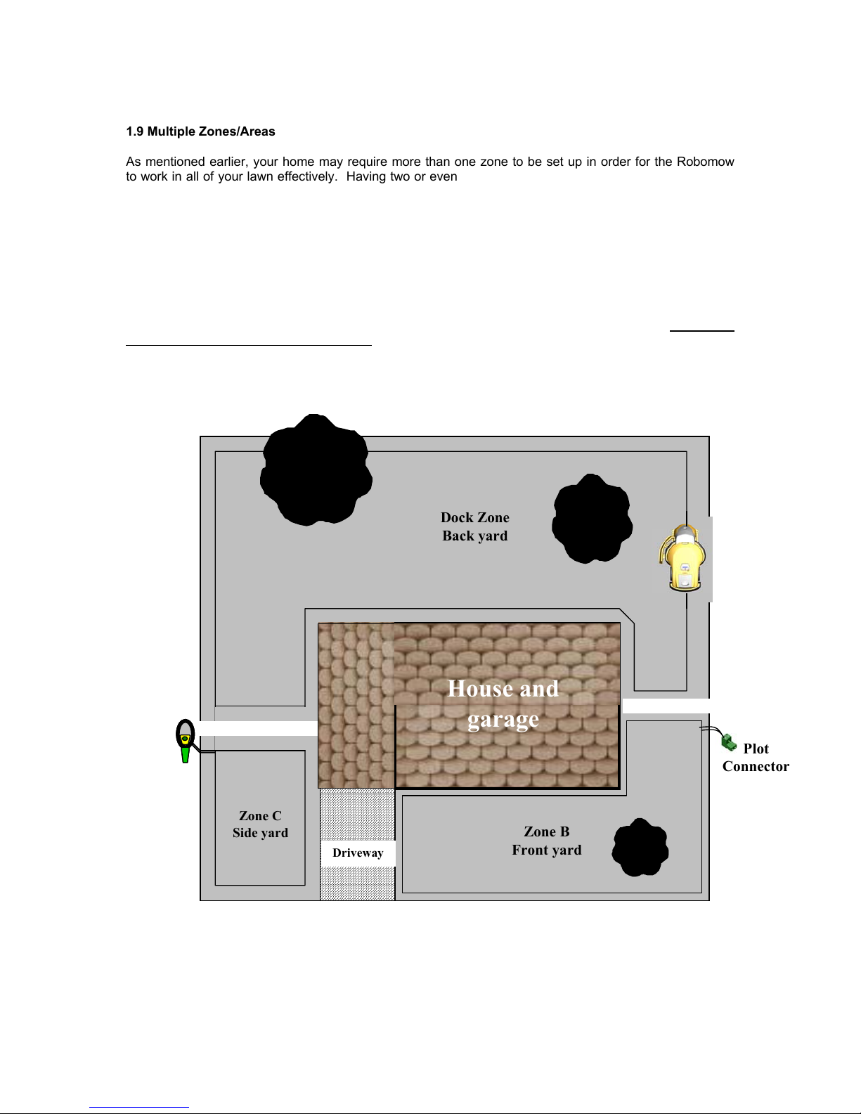
1.9 Multiple Zones/Areas
As mentioned earlier, your home may require more than one zone to be set up in order for the Robomow
to work in all of your lawn effectively. Having two or even three zones does not affect the efficiency of the
Robomow and in many circumstances is more desirable than one large zone. Where grass areas are not
contiguous, or are separated by fences or other objects, it is also recommended to make each of these a
separate zone. A simple but effective and common way to set the Robomow up is to have one zone for
the front yard and one for the back yard, where one zone is a docking zone.
The key is to set up the zones that will allow the Robomow to operate with the greatest efficiency, even if it
is more than one or two zones. You will quickly find that mowing the lawn in these zones is an easy
process that will allow you greater flexibility in your mowing habits. The Robomow gives you the ability to
control the operating time for each zone independently, up to four different zones. In this way, if one zone
needs a shorter operating time than another, it can easily be set for such a process. See Chapter 6,
Operator Settings and Advanced Features for detailed information on how to use this feature. There are
several ways to set up these zones, including the placement of the Perimeter Switch, depending on the
actual layout of the lawn. Examples are given in figures 1.14 and 1.15.
Figure 1.15 – One Perimeter Switch for Multiple Zones With One Docking Zone

21
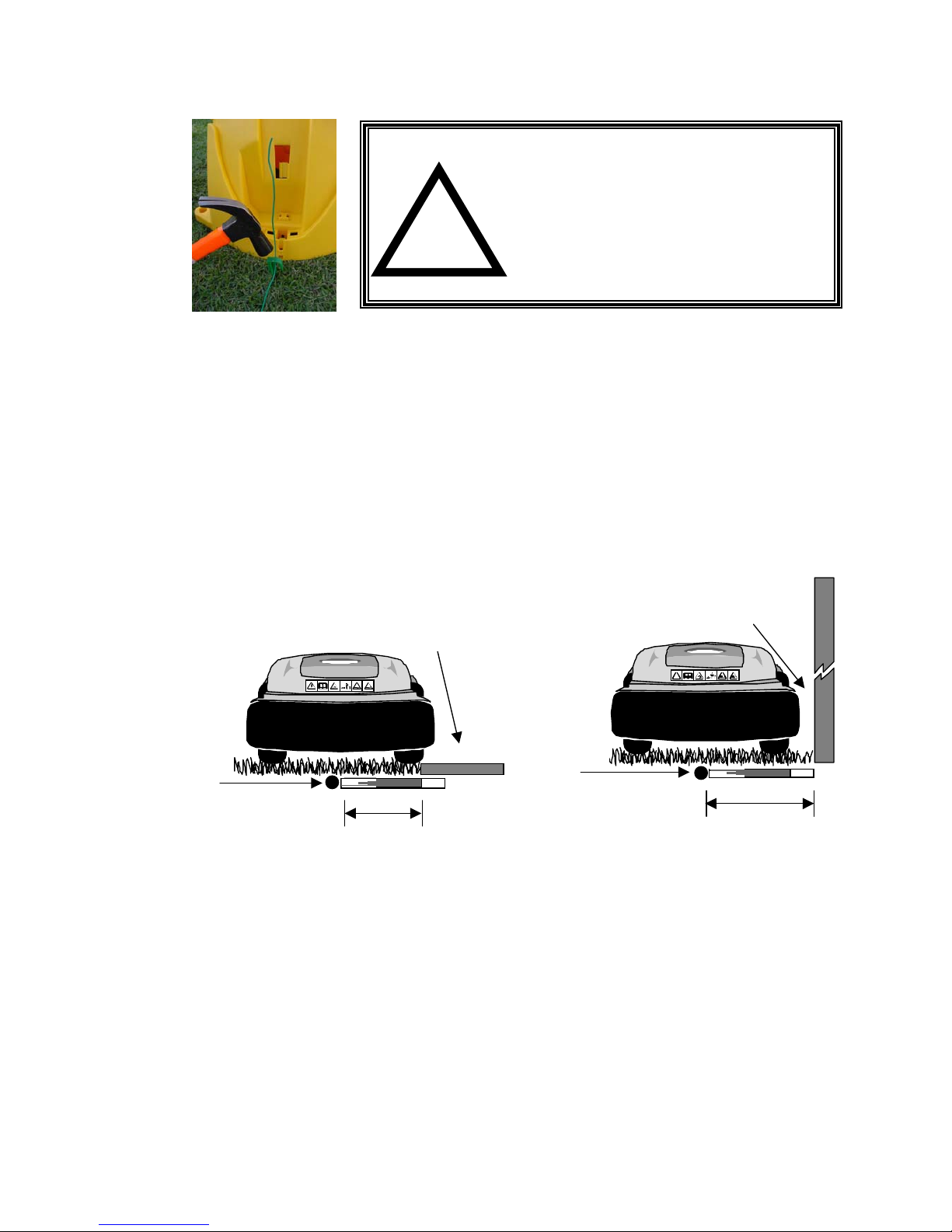
1.10 Slopes
As a general rule of thumb, any slope that can safely be cut using a walk behind mower can also be cut
using the Robomow in the automatic mode. The maximum slope limit is 15 degrees, the same as a
traditional walk behind mower. Bear in mind that a 15-degree slope, though it may not sound very steep, is
in fact a relatively steep slope. In cases where it is attempted to operate the Robomow on a slope that is
too severe, normally the front of the machine will try to rise from the ground surface slightly when climbing
the slope vertically. The lift sensor will then activate, shutting the blades down for safety. The mower will
drop back into position and may attempt the maneuver again. In any event, a slope that causes the front
of the mower to raise from the ground while climbing is too steep and should not be included as part of the
cutting area. In some cases, this area can be cut manually with the Robomow, using the manual
controller. Insure that you can maintain a sure and safe footing before attempting to cut a slope area in
manual. If you are unsure as to whether a slope is too steep or not, attempt driving the Robomow manually
up the slope. If the front of the mower does not lift from the ground, the slope is fine to include in the cutting
area. If however it does lift, exclude this section from the cutting area.
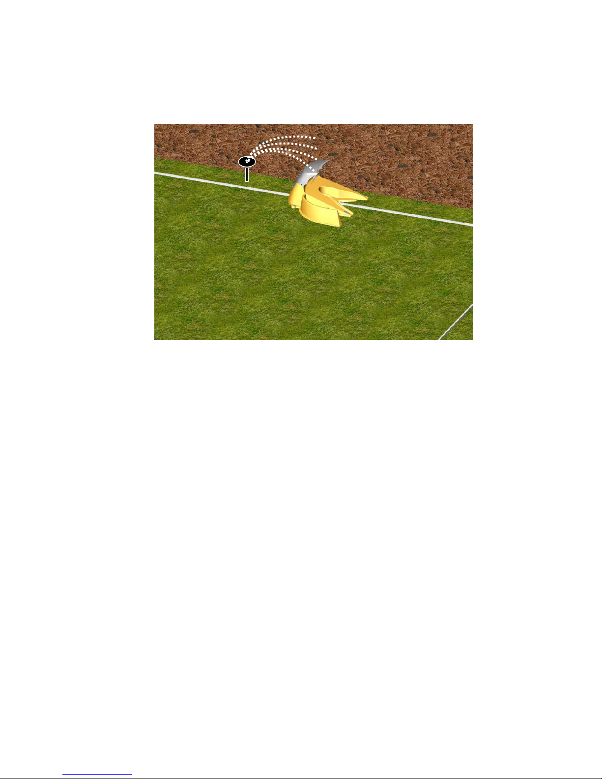
1.11 Completing The Perimeter Wire Setup – Docking Zone
Once the perimeter wire is completed and pegged to the ground, the last step to complete is
attaching the perimeter wire ends to the docking board and testing the setup.
Properly installed perimeters wire will have two loose wire ends located where the perimeter wire
set up was started, the wire end from the start of the perimeter installation and the wire end from
finishing the perimeter installation. See Figure 1.16.
Use the same peg to fasten these two perimeter wire ends down to the ground and twist them as
shown in figure 1.16.
Cut the two loose perimeter wires so they are of equal length (Minimum length of 8 inches/20cm) -
removing any excess wire.
Strip back ¼ inch (6 mm) of insulation from each wire end. See figure 1.16.
Thread the two wire ends through the center aperture in the base and insert each perimeter wire
into hole of connector using a small flat screwdriver, tighten these two screws to secure the
perimeter wires into the connector. See figure 1.17.
Severe injury can occur. When attempting to mow sloped
areas that are too steep for automatic operation of the
Robomow, insure that you can maintain a safe and sure
footing before attempting to mow. Cut across slopes for
safety. Always wear appropriate closed toe shoes when
operating the Robomow manually.
!
WARNING
!
Figure 1.16 Figure 1.17
Completing the Perimeter Wire
Setup in a Docking Station zone
22
1.12 Assemble Power Supply Cord to Docking Board
Before securing the power cord to the Docking Station, carefully lay the length of the cord out,
beginning from the Docking Station and leading to the main power supply to insure that the
Docking Station is placed close enough to the main power for the supply cord to reach.
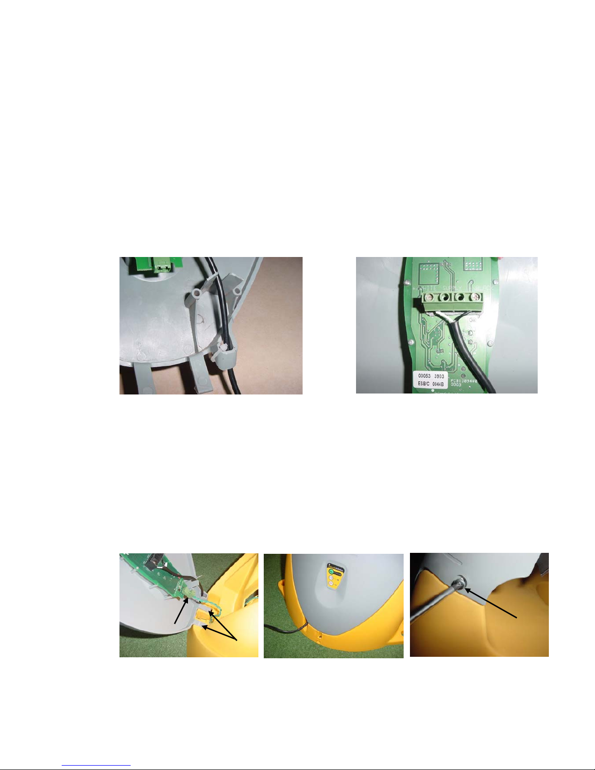
Route the power supply cord into the Docking Station cover as shown in Figure 1.18, with the
white lead positioned at the LH screw and the black lead positioned at the RH screw. Place each
wire under its’ respective screw and tighten firmly with a small screwdriver. See Figure 1.19.
Lastly, place the provided nylon wire tie through the holes in the power cord-retaining slot and
tighten snugly. See Figure 1.18.
The power supply for the Docking Station must be attached to the Docking Station cover at the
control board prior to assembling the cover to the base. Refer to Figure 1.1 for base and cover
identification. Located on the back of the cover you will find the operating control board and the
two screw connectors for attaching the power supply cord. The power supply cord has two leads,
white and black. It is required that the white lead be located on the LH screw (when viewing the
board) and the black wire attached to the RH screw. As a guide, the board is marked Black and
White above its’ respective screw. See Figure 1.19.
1.13 Docking Station Assembly
Align the two tabs on the lower section of the cover with the mated openings in the front lower
section of the base, see Figure 1.20. Carefully push the tabs of the cover into the openings in the
base as shown. While in the position pictured, attach the perimeter wire connector to the
Perimeter Switch board as shown.
Pivot the cover towards the base and confirm proper way out of the power supply cable from the
notch in the base, as shown in Figure 1.21.
Insert the two screws provided on both sides of the top section of the cover. Lightly tighten with a
Phillips screwdriver. See figure 1.22.
Figure 1.20 –
Cover and Base Assembly
Figure 1.18
Routing the Power Supply cord into the cover
+/WHITE SUPPLY -/BLACK
Figure 1.19
Power Supply Cord Track through the cover
Cover tabs
Perimeter wire
connector
Figure 1.21 –
Proper position of the
Power Supply cable
Figure 1.22 –
Cover and Base Assembly
Cover
Base
Screws –
 Loading...