


RL550

Operating & Safety
Manual
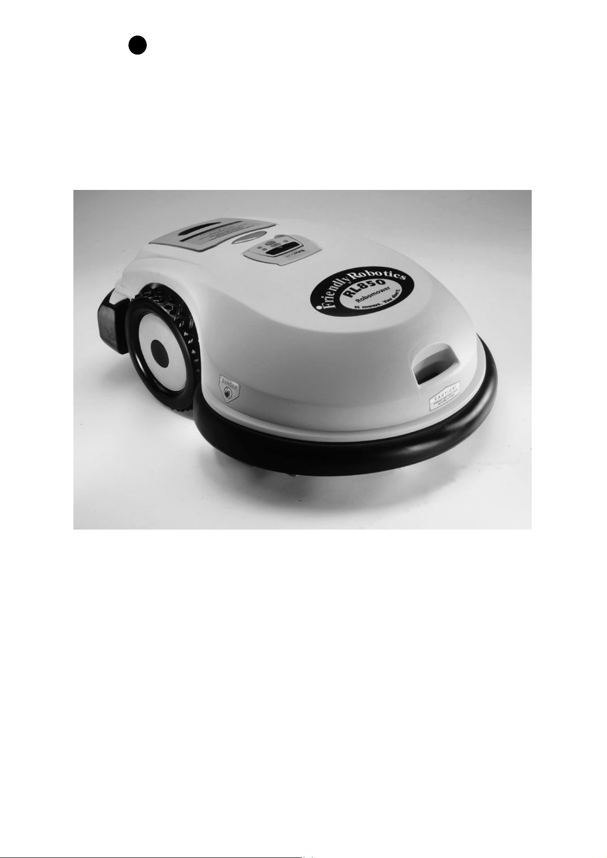
Robomow
RL500 / RL550
RL800 / RL850
www.friendlyrobotics.com
DOC0012A

EC Declaration of Conformity
1.
F. Robotics Acquisitions
, 1 Ha’yassur St., Hasharon Industrial Park, Kadima, Israel
declares that the machines described in item 2 conforms with the directives listed in items
3 &
4.
2. Product: 24 Volt Battery operated automatic lawn mower,models RL500, RL550, RL800 and
RL850*.
Serial number: see mark on the machine.
3.
Tested by the British Standards Institude (BSI) to comply with The supply of Machine (Safety)
Regulation 1992 Essential Health and Safety Requirements relating to the design and
construction of machinery.
The following European standards were taken into consideration when testing the machine:
EN 292: Parts 1 and 2:1991, Safety of Machinery - Basic concepts, general principles for
design.
EN 294: 1992, Safety of Machinery - Safety distances to prevent danger zones being reached
by the upper limbs.
EN 418:1992, Safety of Machinery - Emergency stop equipment, functional aspects -
Principles for design.
EN 60204: Part 1:1997, Safety of Machinery - Electrical equipment of machines - general
requirements.
EN 60335: Part 1:1994, Safety of household and similar electrical appliances.
In addition the following National standard and draft were taken into consideration when
testing the machine:
BS 3456: Part 2: Section 2.42: 1997, Safety of household and similar electrical appliances -
Section 2.42 Battery-operated lawnmowers.
PrEN 50338: 1999, Safety of household and similar electrical appliances –Particular
requirements for pedestrian controlled battery powered electrical lawnmowers.
Noise level testing was conducted to the requirements of: 79/113/EEC and 88/181/EEC.
Results are published by BSI in report number 282/4077203 dated 14 July 2000.
Marylands Avenue, Hemel Hempstead, Hertfordshire HP2 4SQ, UK.
4. Also tested by Hermon Laboratories to comply with The Electromagnetic compatibility
directive 89/336/EEC. Results are published By Hermon Laboratories in report number
Frienmc_EN.14123 dated 21 June 2000.
Rakevet Industry Zone, Binyamina, 30550, Israel.
5. Measured sound power level: 85 db.
6. Guaranteed sound power level: 90 db.
7. Technical documentation kept by Mr. Dedy Gur, QA director.
I hereby declare that the above product conforms to the requirements as specified above.
*The original RL500 was tested by BSI in 2000. All Friendly Robotics models currently sold were
tested by F.Robotics Acquisitions Ltd.
Issued at Shai Abramson – Senior VP R&D
Kadima, Israel
___________________
FriendlyRobotics
FriendlyRobotics, 2003-A Eur. All rights reserved. No part of this document may
be photocopied, reproduced, electronically or otherwise or translated without the
prior written consent of FriendlyRobotics.
Product, product specifications and this document are subject to change without
notice. All other trademarks are the property of their respective owners.
CE approved
•
•
FriendlyRobotics
Welcome…
Welcome…Welcome…
Welcome…
To the world of robotic lawn mowing with the FriendlyRobotics Robomower. Thank you
for purchasing our product. We know that you will enjoy the extra free time you will have while
using Robomower to mow your lawn. When installed and used properly, Robomower will
operate safely on your lawn and provide you with a quality of cut matched by few mowers of
any kind. You will be impressed with your lawns’ appearance and best of all Robomower did it
for you.
IMPORTANT!
The following pages contain important safety and operating instructions.
Please read and follow all instructions in this manual. Carefully read and
review all safety instructions, warnings and cautions contained in this manual.
Failure to read and follow these instructions, warnings and cautionary
statements may result in severe injury or death to persons and pets or damage
to personal property.
Welcome
Page 2
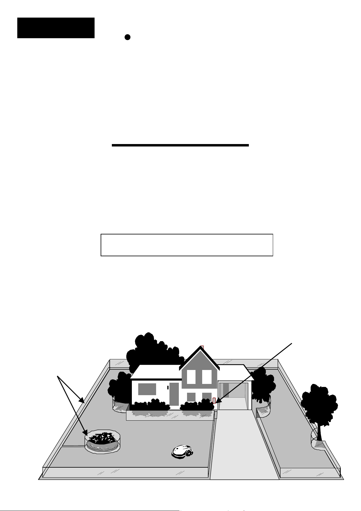
Perimeter switch turned
on to generate signal
Virtual wall, visible
only to the
Robomower.
A small wire, called the perimeter wire, is placed around the perimeter of the lawn and any other areas
where you do not want the mower to enter. A small signal is generated from a device attached to the
perimeter wire, called the Perimeter Switch. When turned on, this signal is carried through the perimeter
wire, creating what we define as a virtual wall. The virtual wall is visible only to the Robomower, keeping
the Robomower where you want it, on your lawn. The perimeter switch must be turned on to activate the
perimeter wire before the Robomower will operate.
A Basic How It Works
x

Safety Warnings & Precautions
1. Read the owners/operating manual carefully and follow all
safety and warning instructions.
2. Keep bystanders, children and pets away from mower when in
operation.
3. Never allow anyone to ride or sit on mower.
4. Never allow children or persons not familiar with the safe
operation of the mower to operate the mower.
5. Keep hands and feet away from the cutting blades and other
moving parts.
6. Never attempt to service or adjust the mower while it is in
operation.
7. Inspect and clear the mowing area of all debris before
operating the mower.
8. Never raise the mower or attempt to inspect the blades while
the mower is operating.
9. Always remove the power pack before lifting the mower or
attempting any adjustments.
10. When operating the mower in manual mode, maintain a safe
distance from behind or around the mower and wear proper
foot apparel.
11. Do not operate the mower on slopes greater than 15 degrees
or use it in manual operation on slopes where a firm footing is
not possible.
12. Do not operate the mower if any safety feature or device is
damaged or inoperable.
13. Do not attempt to disable or defeat any safety feature or
device.
14. Use heavy gloves when inspecting or servicing the blades.
15. The charger is for indoor use only. Do not use in areas where
moisture or water is likely.
16. Wear eye protection and use gloves when installing the
perimeter wire and driving the wire stakes/pegs.
SAFETY
Page 3

Safety Warnings & Precautions
Warning Decal Definitions
1. WARNING-this is a dangerous power tool. Use care when operating and
follow all safety instructions and warnings.
2. Read the owner/operating manual carefully and follow all safety
instructions.
3. Objects can be thrown from mower while operating, take caution.
4. Keep children, pets and bystanders away from mower.
5. Sharp rotating blades. Keep hands away and do not attempt to lift
mower from this area.
6. Sharp rotating blades. Keep feet away.
DANGER! Sharp rotating blades. Keep hands and feet away.
Serious injury can occur.
CAUTION! Remove battery/power pack before
attempting to lift mower for any reason.
1
2
3 4 5 6
SAFETY
Page 4

Robomower RL500/RL550/RL800/RL850
Safety Features
1. Child Guard / Safety Guard
This menu option offers a safety feature to help prevent children or others not familiar with the
safe operation of the mower to operate it freely.
2. Lift Sensor
There is a sensor located on the front caster wheel of the mower. In the event the front of the
mower is raised approximately 1-inch from its resting position on the ground during blade
operation, the blades will stop rotating immediately (< 1 second).
3. Sensor Equipped Bumpers
The front and rear bumpers are equipped with contacts that will activate when the mower
strikes a solid, fixed object when that object is at least 6-inches in vertical height from the
supporting surface of the mower. W hen the bumper sensor is activated, the mower will stop
movement in that direction and reverse itself away from the obstacle. In manual blade
operation, bumper activation will stop the rotation of the blades immediately (<1 second).
4. Emergency Stop Switch
Located on the top outer surface of the manual controller, red in color. Pressing this button at
any time during operation will stop all mower movement and stop the rotation of the blades
immediately (<1 second).
5. Automatic Mode Recognition
The Robomower is designed so that it cannot be operated in the manual mode while the
Manual Controller is in its’ pocket and it cannot operate in the automatic mode while the
Manual Controller is removed.
6. Two-Step Operator Presence Control
While in manual mode, it requires two independent finger actions in order to engage the
mower blades. Once engaged, the mower blade button must remain depressed to continue
blade operation. Once released, the two-step engagement process must be repeated.
7. Electronically Controlled Charging System
The Robomower is equipped with an on-board charge control system. This allows you to
keep the charger connected at all times, even after the battery is fully charged. The control
system will prevent an overcharge to the battery and keep it fully charged and maintained for
the next use.
8. Sealed Power Pack
The power pack that operates the Robomower is completely sealed and will not leak any type
of fluids, regardless of position. In addition, the power pack contains a one-time-use fuse in
the event of a short-circuit or power malfunction.
SAFETY
Page 5

9. Perimeter Switch and Perimeter Wire
The Robomower cannot operate without a perimeter wire installed and activated through the
Perimeter Switch. In the event the Perimeter Switch is turned off or otherwise fails to function, the
Robomower will stop operating. Likewise, should a break in the perimeter wire occur the
Robomower would again stop operation. A break in the perimeter wire prior to operation will
prevent the Robomower from operating. The Robomower can only operate within the boundary
of the perimeter wire.
10. Auto-Off Perimeter Switch
The auto-off feature of the perimeter switch shuts down the perimeter switch operation after
approximately 5 hours of continuous operation. This is typically 1 to 2 hours after which a fully
charged Power Pack will need to be re-charged. This helps to prevent unauthorized persons from
attempting to re-start the Robomower after it has completed its’ operation.
11. Over-Current Monitoring Protection
Each of the three blade motors and each of the two wheel drive motors are monitored
continuously during operation for any situation that may cause these motors to over-heat. In the
event this is detected, the Robomower will stop operation of at least that motor and possibly the
mower itself and indicate that the motor is cooling down. W hile unusual, this may happen when
the mower is put in grass that is severely overgrown; the underside of the mower is clogged from
poor cleaning maintenance; the mower has encountered an obstacle that is unable to activate the
bumper sensor preventing it from moving; or a problem landscape area has caused the mower to
get stuck and is preventing it from moving.
This warning symbol will be found at several points throughout
the pages of this owner/operator manual. It is intended to
highlight an important safety, warning or cautionary message.
Please pay particular attention to these areas and be sure you
fully understand the message before proceeding.
WARNING!
!
SAFETY
Page 6
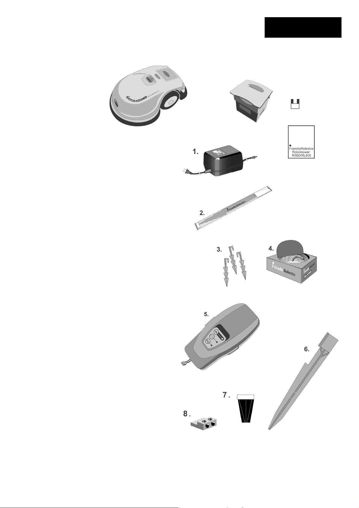
What's in the Box
What's in the Box
Page 7
Robomower
Power Pack
Power Pack Fuse
(Must insert to operate)
Operating Manual
1. Standard Charger
Used for recharging the Robomower power
pack.
2. RoboRuler
Used for setting the distance of the perimeter
wire from the lawn edge.
3. Pegs
Used for securing the perimeter wire to the
ground around the lawn perimeter and
around obstacles.
4. Wire
Used to create a virtual wall for your
Robomower
5. Perimeter Switch & C-Cell Batteries
Activates the perimeter wire, which defines
the area in which the Robomower will
operate.
6. Perimeter Switch Mounting Stake
Used for supporting the perimeter switch in
the lawn.
7. Wire Connectors
Used for splicing wires (as needed).
8. Plot Connectors
Used for connecting the completed
screwdriver perimeter wire installation to the
perimeter switch.
NOTE: Tools needed, but not included: hammerwire
cutters, small flat- head screwdriver
Operating
Manual

Table of Contents
Welcome, Basic How It Work ………………………………………………..2
The world of automatic mowing with the Robomower
Safety Warnings and Precautions…………………………………………….3
Safely operating the Robomower
What’s In The Box………………………………………………………………..7
A list and descriptions of the items found in the Robomower box
Chapter 1 – Perimeter Wire Setup…………………………………………….9
Setup of the perimeter wire in your lawn
Chapter 2 – Preparing The Robomower……………………………………..16
How to get the Robomower ready for the first use
Chapter 3 – Automatic Operation……………………………………………..21
Operating the Robomower in automatic mowing (Robotic mowing)
Chapter 4 – Power Pack and Power Management…………………………23
Proper use and maintenance of the Power Pack and charging system
Chapter 5 – Manual Operation………………………………………………. 25
How to use the Robomower in manual mode
Chapter 6 – Settings and Advanced Features……………………………. 26
Settings and features for the customer to choose
Chapter 7 – Messages and Troubleshooting……………………………… 30
Understanding the text messages and troubleshooting
Chapter 8 – Specifications……………………………………………………. 34
General product specifications
Chapter 9 – Care and Maintenance…………………………………………. 35
How to care and maintain your Robomower
Chapter 10 – Accessories…………………………………………………….. 37
Accessories available to enhance the mowing experience
Table of Contents
Page 8
Chapter 1
Perimeter Wire Setup
1.0 Where To Start
In order to determine the best location to begin the setup, it is best to first make some basic
decisions based on your lawn. For each zone that is set up, allow for placement of one
Perimeter Switch for that zone. Find a convenient spot outside the perimeter of each zone that
is relatively easy for you to access. A spot sheltered from the elements is preferred
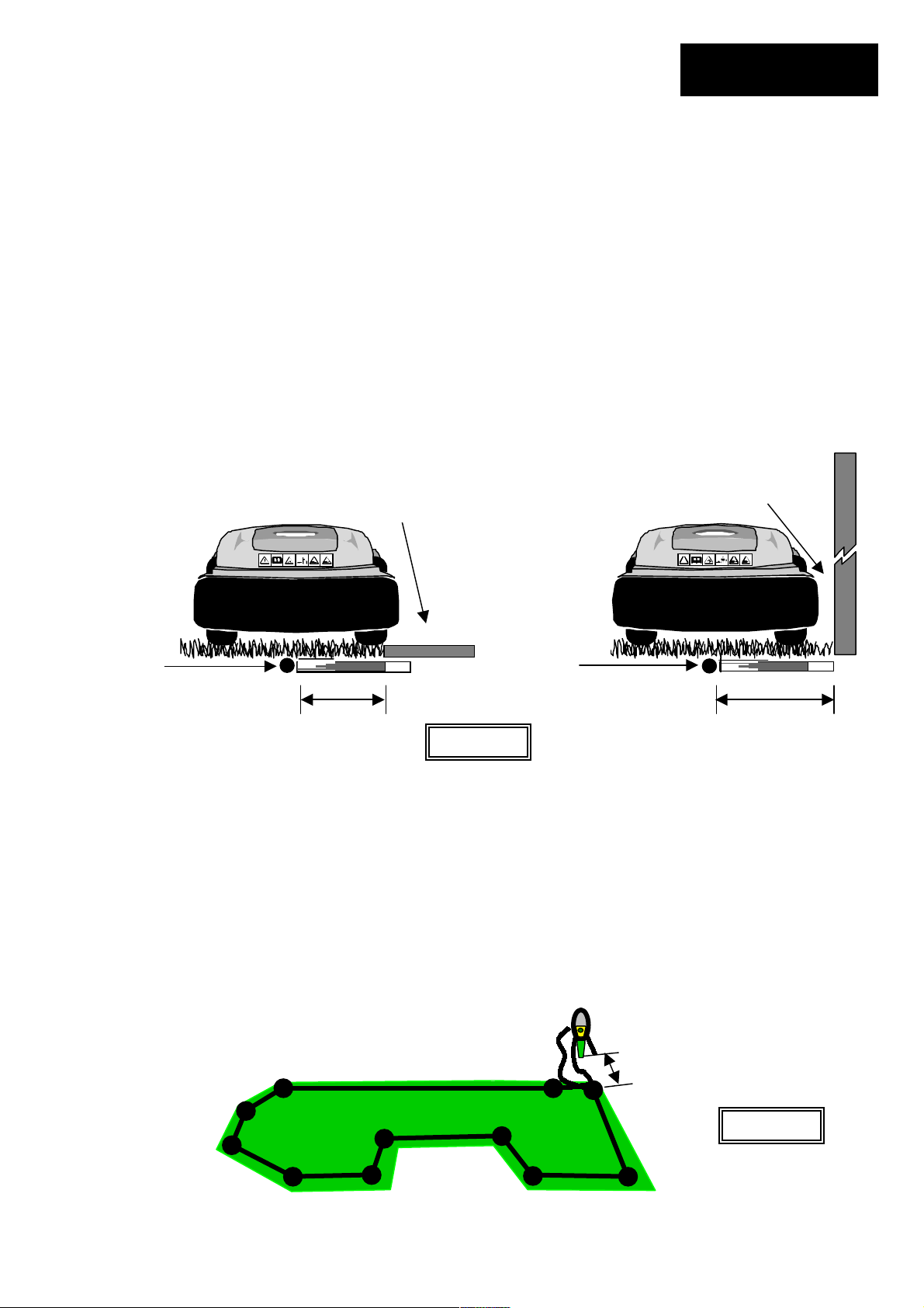
1.1 Using The RoboRuler
There are two basic measurements that are used on the RoboRuler. The shorter distance is
used along perimeter edges where the area outside the immediate perimeter (about 12 inches/30
cm) is free of obstacles and is the same relative height as the perimeter edge. The longer
distance is used along perimeter edges where the area outside the immediate perimeter has
obstacles or differences in the height along the perimeter edge. See Figure 1.1.
1.2 Starting The Perimeter Wire
Tear out the perforated center piece on the perimeter wire box. Puncture the plastic covering
with your finger and feel around inside the center of the wire spool for the end of the wire. Pull
the wire end out of the box. The box is designed as a dispenser for the wire so do not remove
the wire spool from the box. After reviewing the illustrations and instructions in the following
pages you will be ready to lay out the perimeter wire and start pegging it to the ground. Figure
1.2
Leave enough wire at the beginning, where the Perimeter Switch is going to be located. Use the
RoboRuler to help guide you on placement of the wire along the perimeter. Use a minimum
number of pegs at this point, as you will want to test the wire position at the end of the setup.
See Section 2.5 for details on testing the setup.
Area outside perimeter. Has a wall
as an obstacle.
Short distance Lon
g
distance
Perimeter
wire
position
Perimeter
wire
position
Figure 1.1
Area outside perimeter. Same
basic level and free of obstacles.
Chapter 1
Page 9
>5ft (1.5m)
Figure 1.2

1.3 Fastening The Wire To The Ground
Add pegs in to pull the perimeter wire down to the ground surface, below the grass tips Figure
1.3
1.4 Corners & Sharp Turns
Care must be taken not to create a turn sharper than 90 degrees when setting up the perimeter
wire. A turn sharper than 90 degrees can cause the Robomower to lose track of the perimeter
wire. In situations where a corner may require a wire placement of less than a 90-degree angle,
placement can be adjusted using several angles to avoid this. See Figure 1.4.
Correct corner
setup using several angles
to avoid a less than 90-
degree angle.
Perimeter Wire
Add pegs in to pull the perimeter wire
down to the ground surface, below the
grass tips.
Incorrect corner
setup
Figure 1.4
Lawn area
90 degrees
Damage to the eye is possible. Use proper eye protection
and wear appropriate work gloves when hammering the
pegs. Hard or dry ground may cause pegs to break when
driving them in. In extreme cases, watering the lawn where
the pegs will be driven can be beneficial.
Figure 1.3
WARNING!
!
Chapter 1
Page 10
1.5 Narrow Areas And Narrow Passes
The minimum distance for an effective narrow pass is 5.5 feet (1.7 m) between perimeter wires.
Figure 1.8.
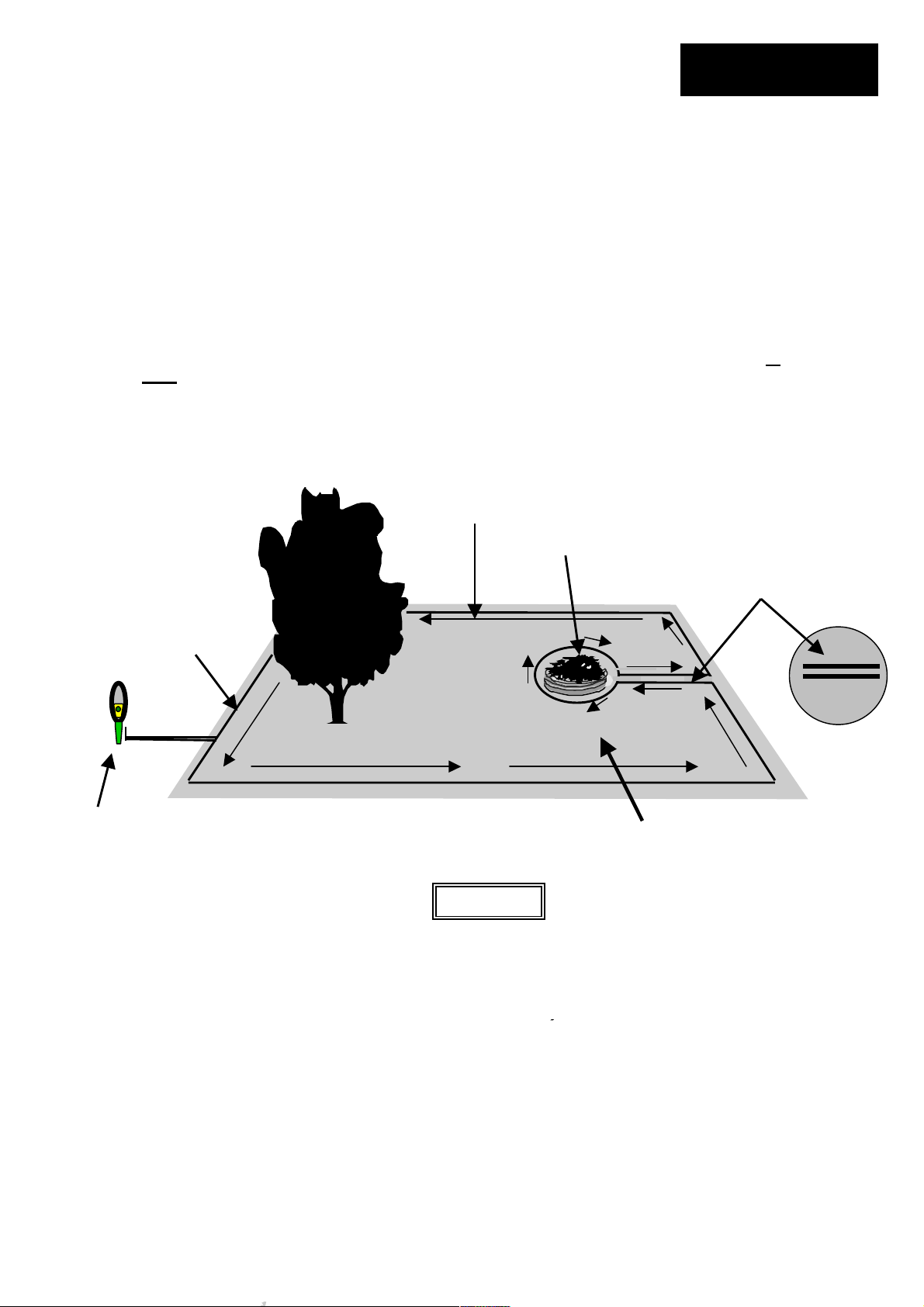
1.6 Defining Obstacles-Perimeter Islands
Many obstacles can be left in the lawn without consideration to excluding them using the
perimeter wire. The basic rule of thumb is that the obstacle must be at least 6 inches (15 cm)
high from the ground and the obstacle must be relatively rigid. Good examples of these kinds of
obstacles include many trees, phone poles, power poles and flag poles.
To create a perimeter island, take the wire from the perimeter section closest to the obstacle and
peg the wire around the obstacle, returning back to the same spot of the perimeter. There are
two keys to setting up the perimeter wire to exclude an obstacle; 1) the two wires going to
and
from
the obstacle should be placed under the same peg (touching) and 2) follow the direction of
set up as shown in Figure 1.6.
Perimeter
wire
Direction of set up
followed around
obstacle
Flower bed
While the picture shows two
wires separate, they should
be adjacent and no more than
1/8 inch (3 mm) from one
another
Figure 1.6
Perimeter switch placed at least 5 feet
(1.5 m) from perimeter. Wires to
perimeter switch should be placed
adjacent, the same as wires leading to
an obstacle.
Direction of
set up
Chapter 1
Page 11
 Loading...