

Friendly Robotics robomower RL350, robomower RL1000, robomower RL550, robomower RL800, robomower RL850 Service Manual

Robomower
®
Service Guide
Read carefully and thoroughly all relevant sections before servicing Robomower.
It is very important to read and follow all warning and safety instructions in this
manual and in the Robomower Operating Manual.
All maintenance procedures and troubleshooting must be carried out exactly as
given in this manual.
All rights reserved. No part of this book may be reproduced or used in any form
or by any means – graphic, electronic or mechanical, including photocopying,
recording, taping or by any electronic information storage and retrieval systems
without a prior written consent of F. Robotics Acquisitions Ltd.
This book was carefully prepared. However, F. Robotics Acquisitions Ltd. will
not bear any responsibility for any errors, mistakes or misunderstandings. F. Robotics
Acquisitions Ltd. shall not bear responsibility for any damage resulting from faulty
instructions in this manual.
F. Robotics Acquisitions Ltd. reserves the right to introduce changes in the
product and/or to this manual without any prior notice.
© 2006. All rights reserved to F. Robotics Acquisitions Ltd.
I

Table of contents
Introduction
Chapter 1- Robomower Layout & IPL’s (Illustrated Parts List)
Chapter 2 - Menu Items
Chapter 3 - Troubleshooting
Chapter 4 - Repair and Maintenance Procedures
Chapter 5 - Diagnostics
Chapter 6 – General Procedures
Chapter 7 - Service Bulletins
II

Introduction
The purpose of this Service Guide is to allow trained and certified technicians to
efficiently inspect, diagnose and repair the Robomower. If you have not completed
training, please contact your manager or supervisor to arrange training completion.
The Service Guide is divided into various sections to allow access to information in an
easy to use format. The sections in the beginning show the layout, wiring, parts and
construction of the Robomower. Mid sections show diagnostic techniques and the last
sections show repair and warranty procedures.
IMPORTANT: it is the policy of F. Robotics Acquisitions Ltd. that all agents, either
directly appointed or appointed by a distributor, should always show a duty of care to
customers. In most countries this is a legal requirement and. F. Robotics Acquisitions
Ltd. policy is to always meet these standards and to surpass them wherever possible.
All units inspected by a technician MUST, as a minimum standard, pass the General
Test prior to return to the customer.
Units which were actually repaired or had a certain part replaced, must go through
specific testing, of that system, in line with the procedures set out in this Service Guide.
The last part of each procedure has the appropriate test for that system.
In addition to testing a specific system or part, a General Test should always be
undertaken to ensure no hidden problems are missed and, most importantly, to ensure that
all safety systems are functioning.
If any doubt exists about diagnosis, repair, testing or any other technical aspect of the
Robomower, always be sure to seek further advice from a qualified source.
Finally, if you have any suggestions for improvement of this guide, either in content,
layout or additional material, please contact F. Robotics Acquisitions Ltd. through the
correct channels and this will be considered for future updates.
III

1. Robomow Layout & Spare Parts
This first section is dedicated to the layout of the Robomow, how it is
constructed, part numbers and identification of parts.
Important: Be sure to review section 1.1 (Orientation). It explains what is referred
to as “right”, “left” etc. Failure to understand this can result in a mistake or problem in
the analysis or repair of the product.
Table of Contents
1.1 Robomow layout and main components………………2
1.2 IPL’s (Illustrated Parts List) ……………………….….6
1.3 Fuse location…….…………………………….………..19
1.4 Board identification ……………………………………20
1.5 Wiring Layout…….…………………………………….22
1.6 Parts List…….…………………………..………………24
1.7 Parts Compatibility Table…….…………..……………30
1
1
1.1 Robomow layout and main components
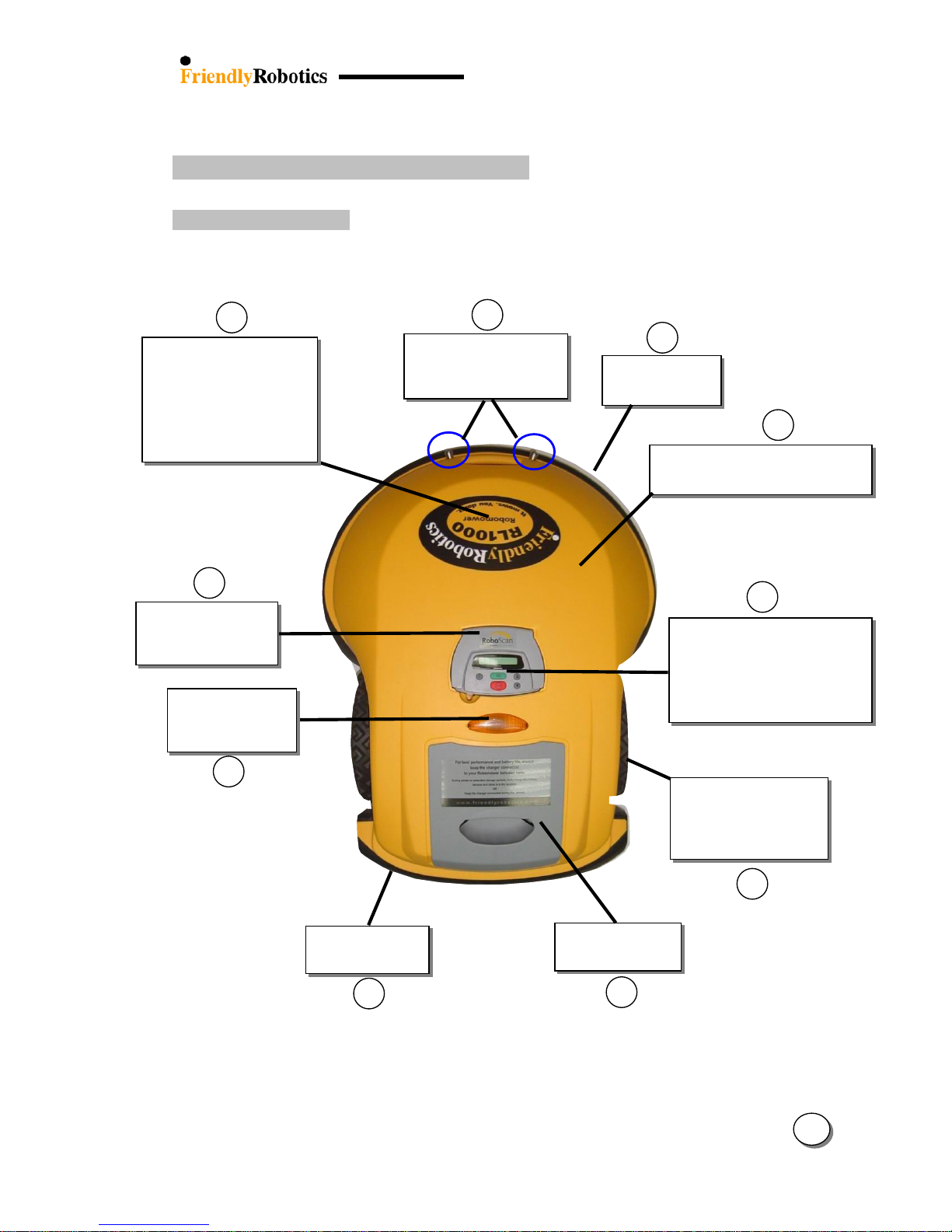
1.1.1 Robomow top view
8
9
10
2
Charging contacts
(for Charging
Station
)
SPP0026A
Knobby drive wheel
MSB0099A
Smooth drive wheel
Manual Controllers
MSB0112A (tones)
MSB0114A (speech)
MSB0118A (ESBC050B+)
MSB0119A (Enhanced)
Manual Controller
holder assembly
Operation lamp
cover
SPP003
2A
Front Bumper
MSB0106B
RL Model Stickers
RL350 – STC0057A
RL800 – STC0051A
RL550 – STC0048A
RL850 – STC0049A
RL1000 – STC0056A
1
RL Yellow Cover GEN0094A
RL Green Cover GEN0227A
Left
Side
Right
side
7
2
6
5
4
3
Power Pack
UNT0009A
Rear
Rear Bumper
MSB0107A
Figure 1.1.1 Top view
1
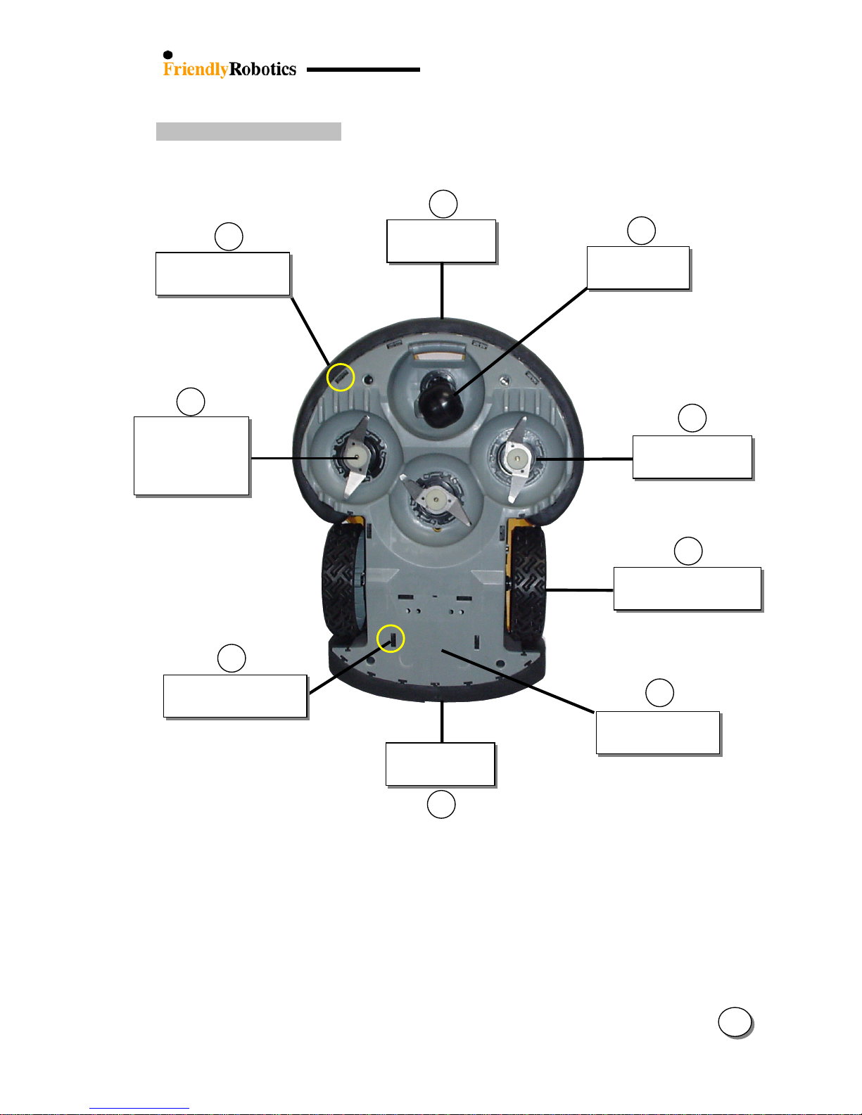
1.1.2 Robomow bottom view
Note: Mower sides are determined by its top view
16
Snap lock (curved)
GEN0163A
(x4)
Snap lock (straight)
GEN0162A
(x6)
11
Front Wheel
SPP0011A
Front Bumper
MSB0106B
12
Mowing Motor
MSB0065B
(x3)
15
High cut blades
MRK0002A
Low cut blades
MRK0003A
14
5
Rear Bumper
MSB0107B
3
Knobby drive wheel
MSB0099A
13
10
RL plastic base
GEN0095A
Figure 1.1.2 Bottom view
1
3
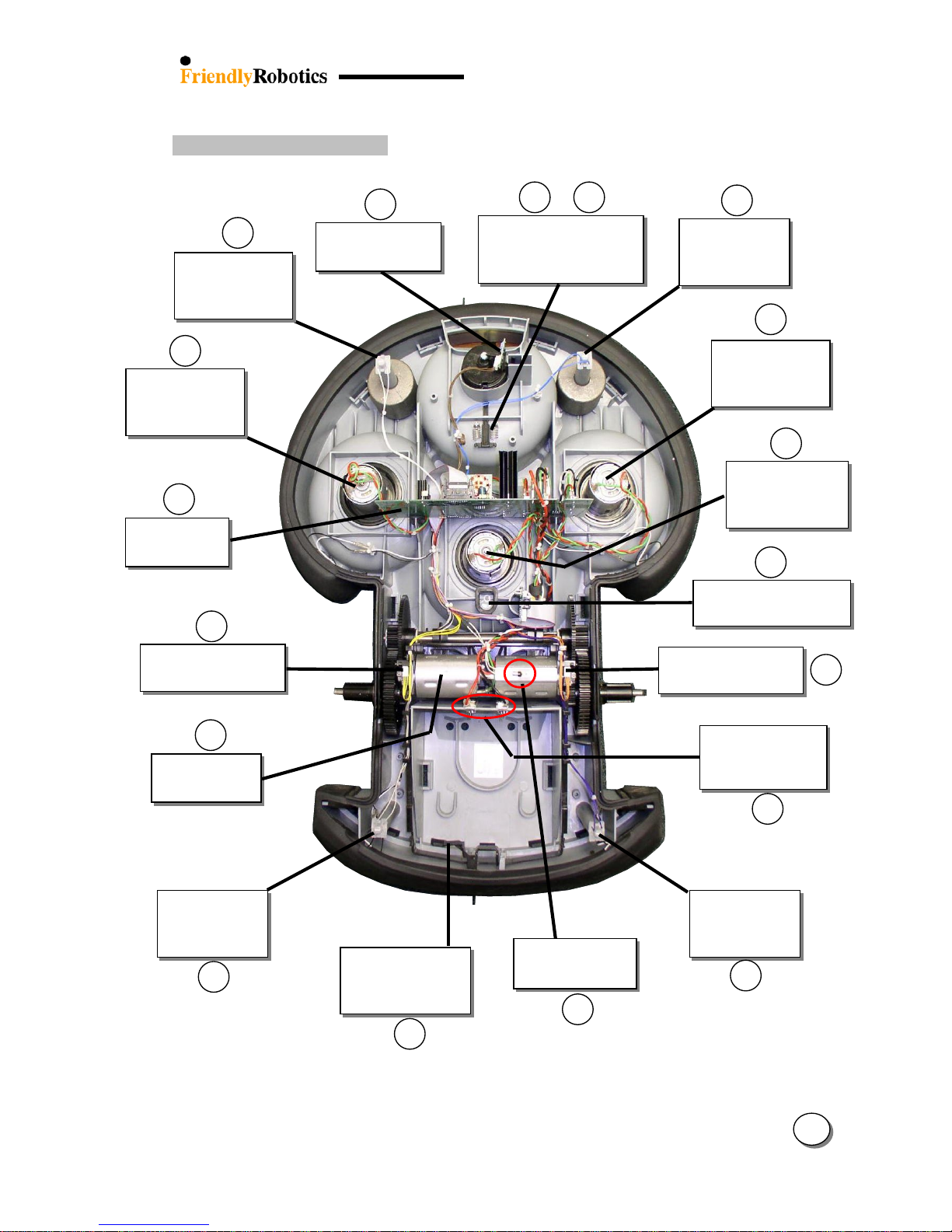
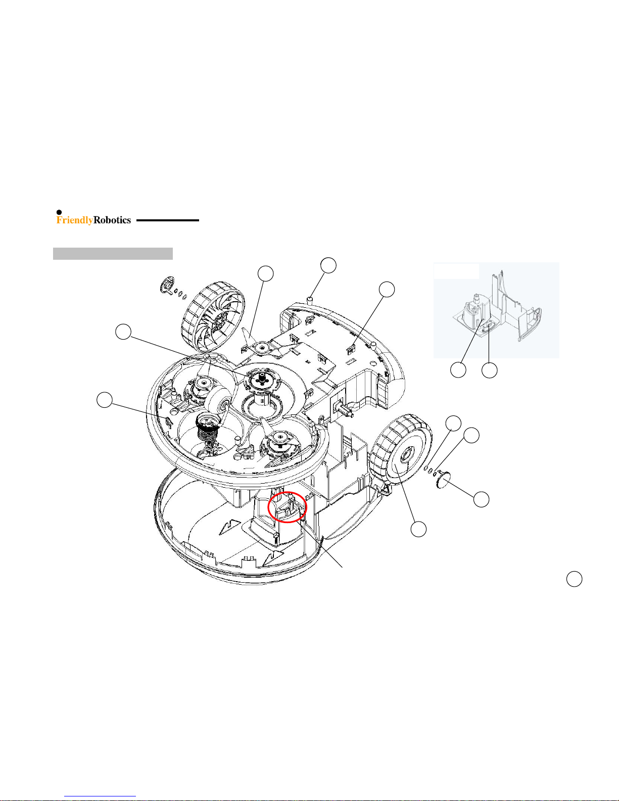
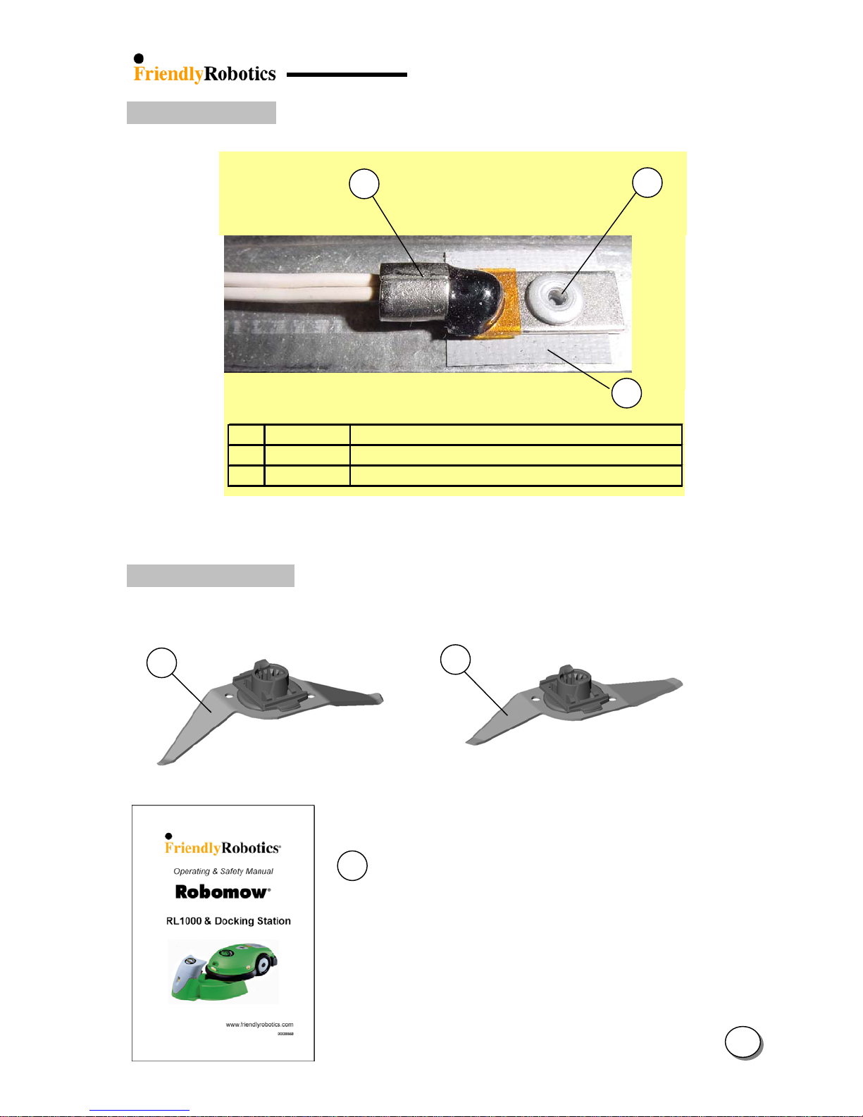
1.1.3 Robomow internal views
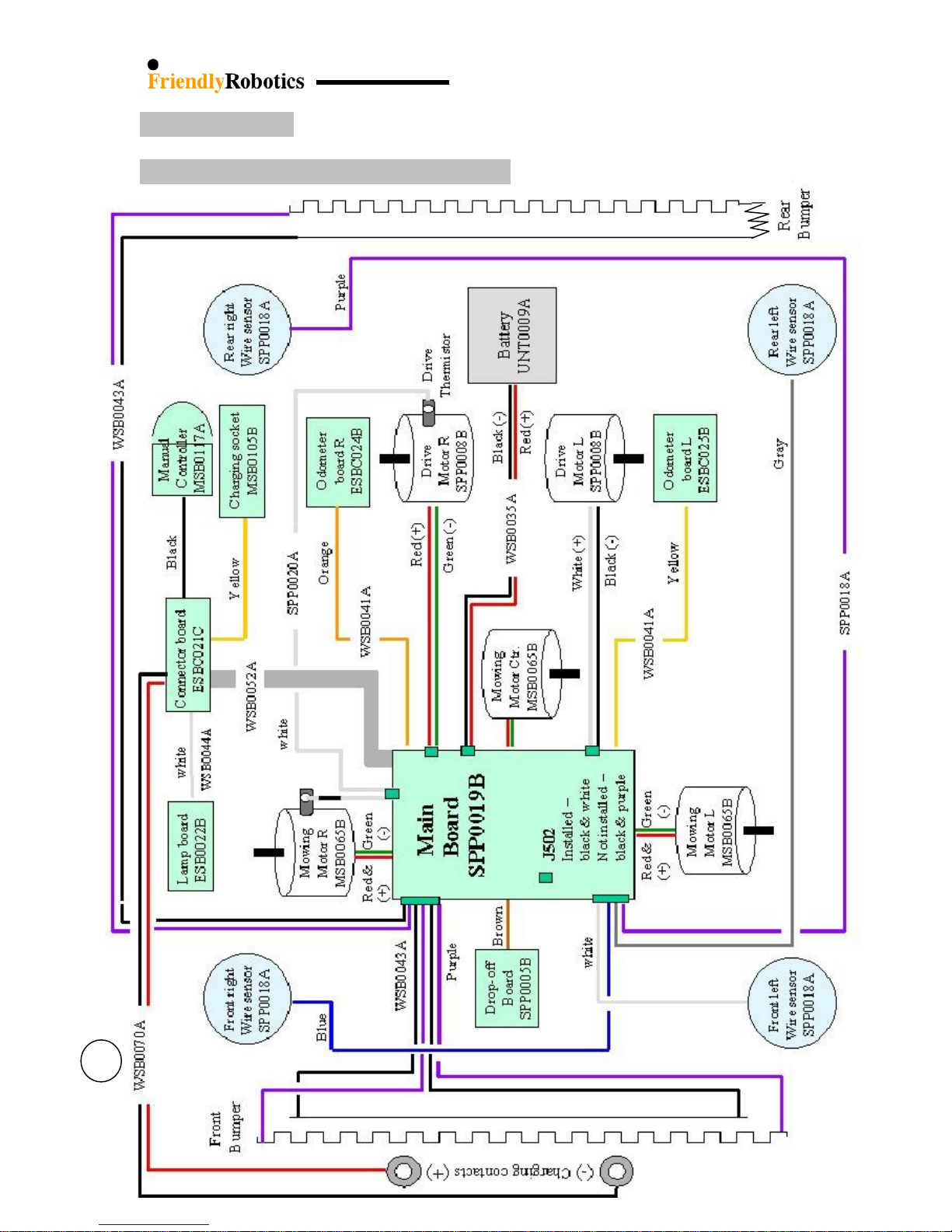
4
Front right
Wire sensor
SPP0018A
Right Mowing
Motor
MSB0065B
Front left
Wire sensor
SPP0018A
Drive Motor
SPP0008B
Thermistor Kit
SPP0020A
Rear right
Wire sensor
SPP0018A
Rear left
Wire sensor
SPP0018A
Cover-base seal ring
GEN0182A
Ground
clearance limiter
GEN0202A
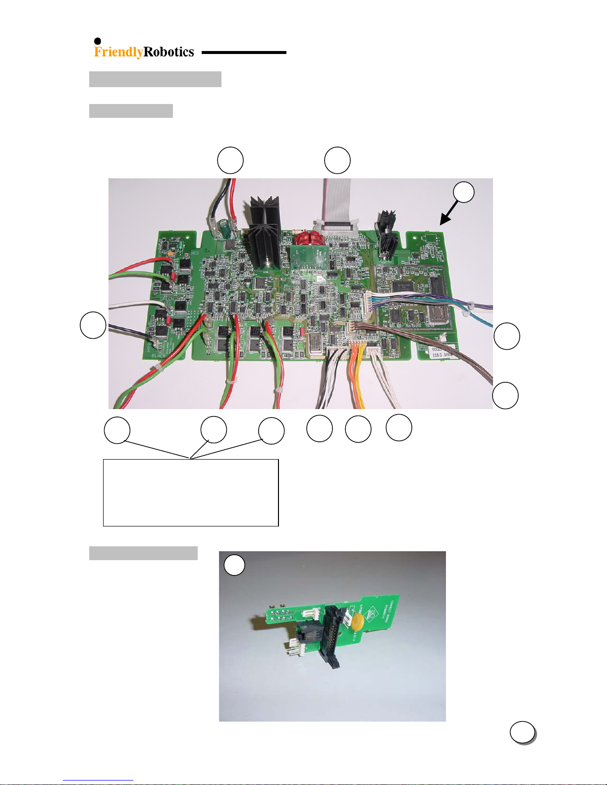
Main Board
SPP0019B
Drop-off Board
SPP0005B
Battery contacts
(RL side)
SPP0014A
Front wheel stopper
GEN0207A
& Spring GEN0208A
Odometer board R
ESBC024C
Center
Mowing Motor
MSB0065B
Odometer board L
ESBC025C
17
21
22
27
&
28
17
82
12
12
Left Mowing
Motor
MSB0065B
12
23
24
25
18
19
20
17
17
Figure 1.1.3 Internal view
1
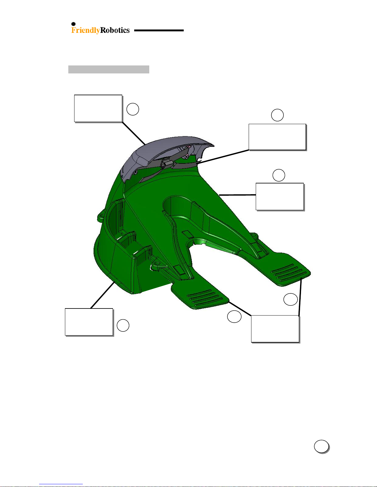
1.1.4 Charging Station views
5
30
Charging
Station Base
SPP0029A
Charging Station
contacts assembly
SPP0031A
32
Charging
Station Cover
SPP0030A
29
Charging
Station Drive
Wheel support
123
122
Charging
Station Fence
GEN0215B
31
Figure 1.1.4 Charging Station view
1

1.2 IPL’s / Exploded views
1.2.1 Robomow – bottom view……………………..…7
1.2.2 Base – top view.…………………………………8
1.2.3 Cover – top view…….……………………….….9
1.2.4 Charging Station…….……………………..…..10
1.2.5 Gear Case ……………………………………...11
1.2.6 Power Pack & Power Supply………………….12
1.2.7 Fuses.....................................................................13
1.2.8 Perimeter Switch…….…………………………14
1.2.9 Bumpers………………………………………...14
1.2.10 Front Wheel…….……………………………..15
1.2.11 Thermistors…….……………………………...16
1.2.12 Add-on Items…….…………………………….16
1.2.13 Decals…….…………………………………….17
1.2.14 Old configuration spare parts………………..18
1
6
1
1.2.1 Robomow bottom view
7
DETAIL A
34
35
36
12
16
14
SEE DETAIL A
39
37
38
3
34
DETAIL A
15
7
1
8
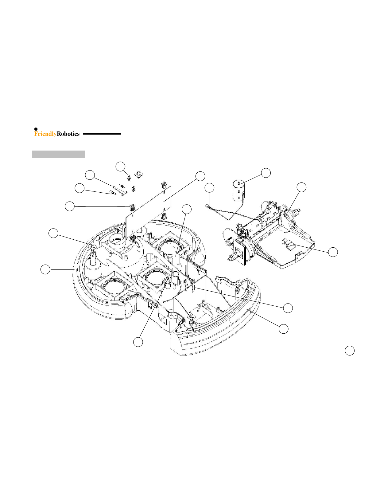
1.2.2 Base - top view
41
42
28
25
44
21
27
40
43
17
22
10
5
18
20
8
1
9
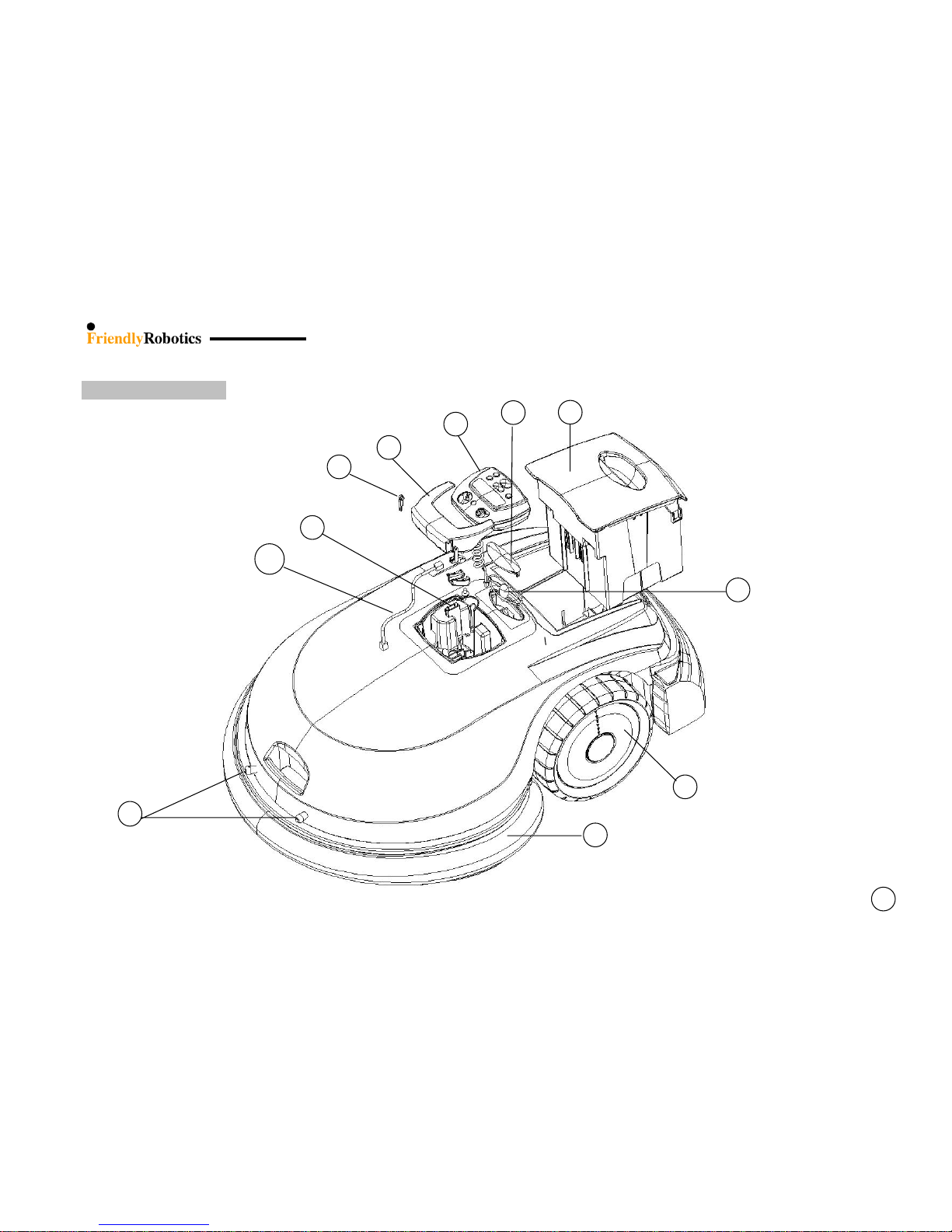
1.2.3 Cover – top view
45
3
46
2
4
105
7
10
9
6
47
9
1.2.4 Charging Station
10
53
30
48
29
31
54
122
123
29
32
48
49
50
127
51
52
1
10
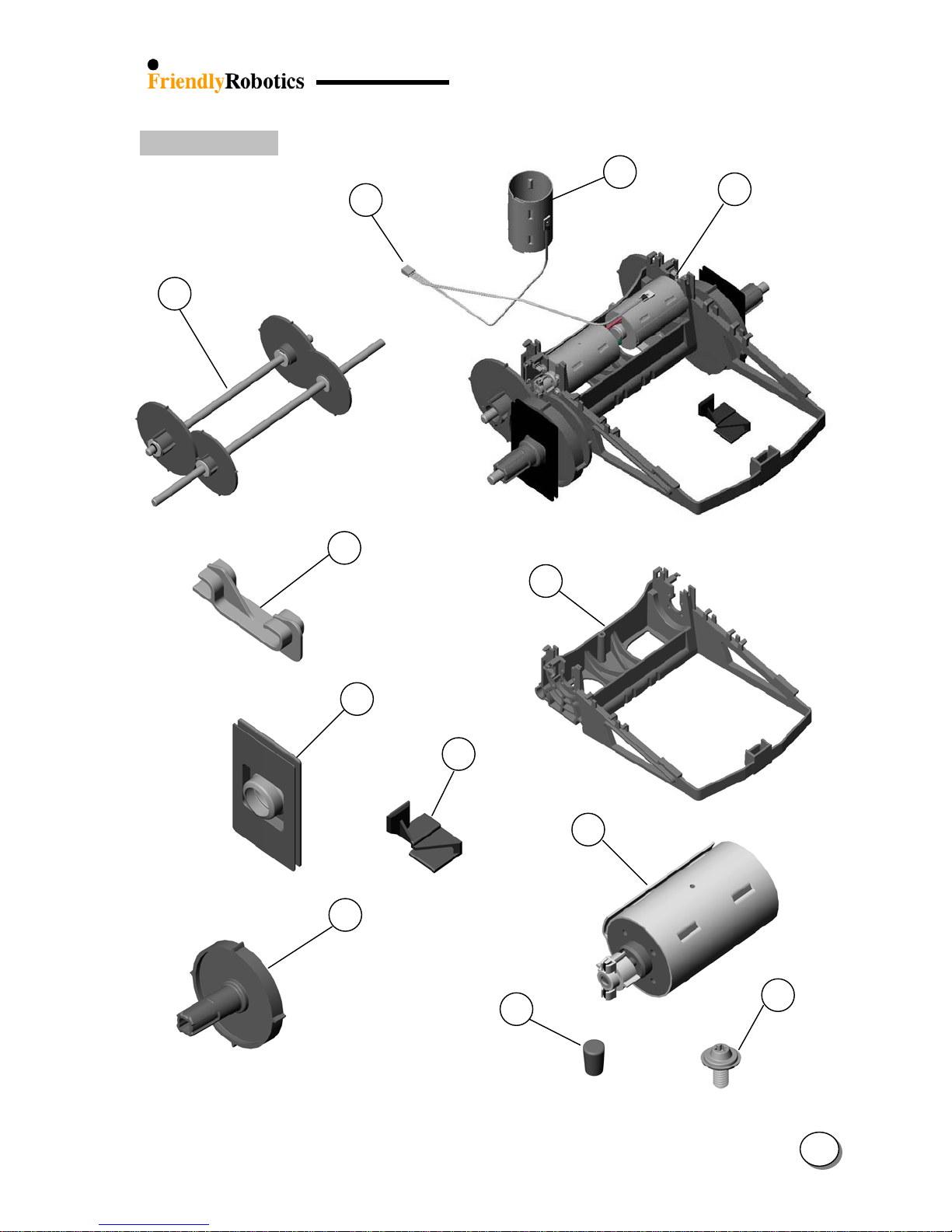
1.2.5 Gear Case
55
21
42
44
57
56
58
22
23
59
60
61
1
11

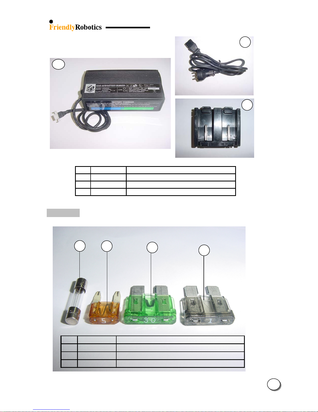
1.2.6 Power Pack & Power Supply
4
62
63
64
NOTE: for Power Pack wiring P/N’s refer to ‘Power Pack wiring diagram’ (Section 1.5.2)
65
66
PWS0004A
PWS0005A
0006A
PWS
230VAC Out Door Power
Supply for RL1000 (EUR)
115VAC Out Door Power
Supply for RL1000 (US)
230VAC Out Door Power
Supply for RL1000 (UK)
1
PWS0001A 230VAC power supply -Europe
PWS0002A 230VAC power supply - UK
PWS0003A 115VAC power supply - US
12
A
A
A
ging
)
67
121
68
67 CBL0037
67 CBL0038
67 CBL0039
68 UNT0016A Power Pack external char
External charger cord - UK
External charger cord - US
External charger cord - EUR
adaptor
1.2.7 Fuses
69 FUS0021A Fuse 5x20 10A 125V (External Charger
70 FUS0015A Fuse mini blade 5A
71 FUS0003A Fuse AT blade 30A 32V
72 FUS0012A Fuse AT blade 1A 32V
69
70
71
72
1
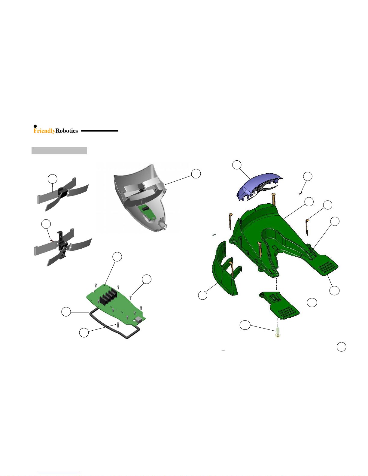
13
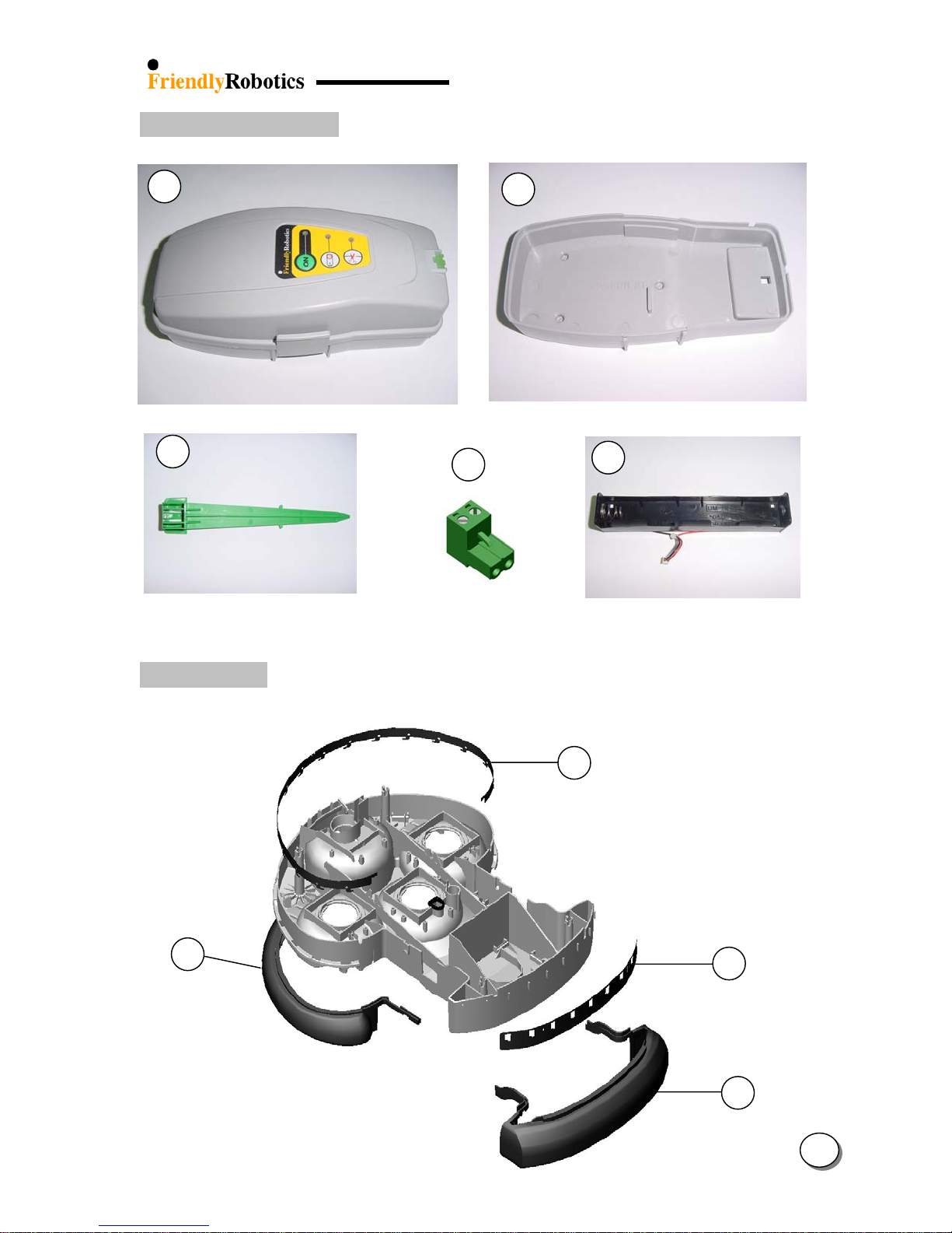
1.2.8 Perimeter Switch
73
75
77
74
76
1.2.9 Bumpers
10
78
79
1
5
14
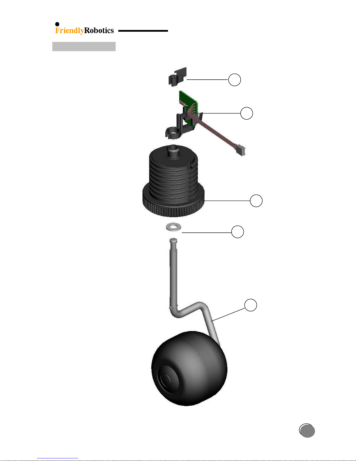
1.2.10 Front Wheel
83
82
81
80
11
1
15
1.2.11 Thermistors
21 SPP0020A Thermistors kit (Includes NIT0009A & HSN0003A)
84 NIT0009A Pop rivet/D3.2x6
85 HSN0003A Heat sink silicone insulator
1.2.12 Add-On Items
21
84
85
15
15
Low cut blades High cut blades
86
DOC0015D – RL Operating Manual (En)
DOC0076B – RL1000 (Standard Manual Con.) + Docking Manual
1
16
87
GEN0211A Charging plug rubber cover
GEN0210A Charging socket rubber cover
88
TOL0001A Mowing motor removal tool
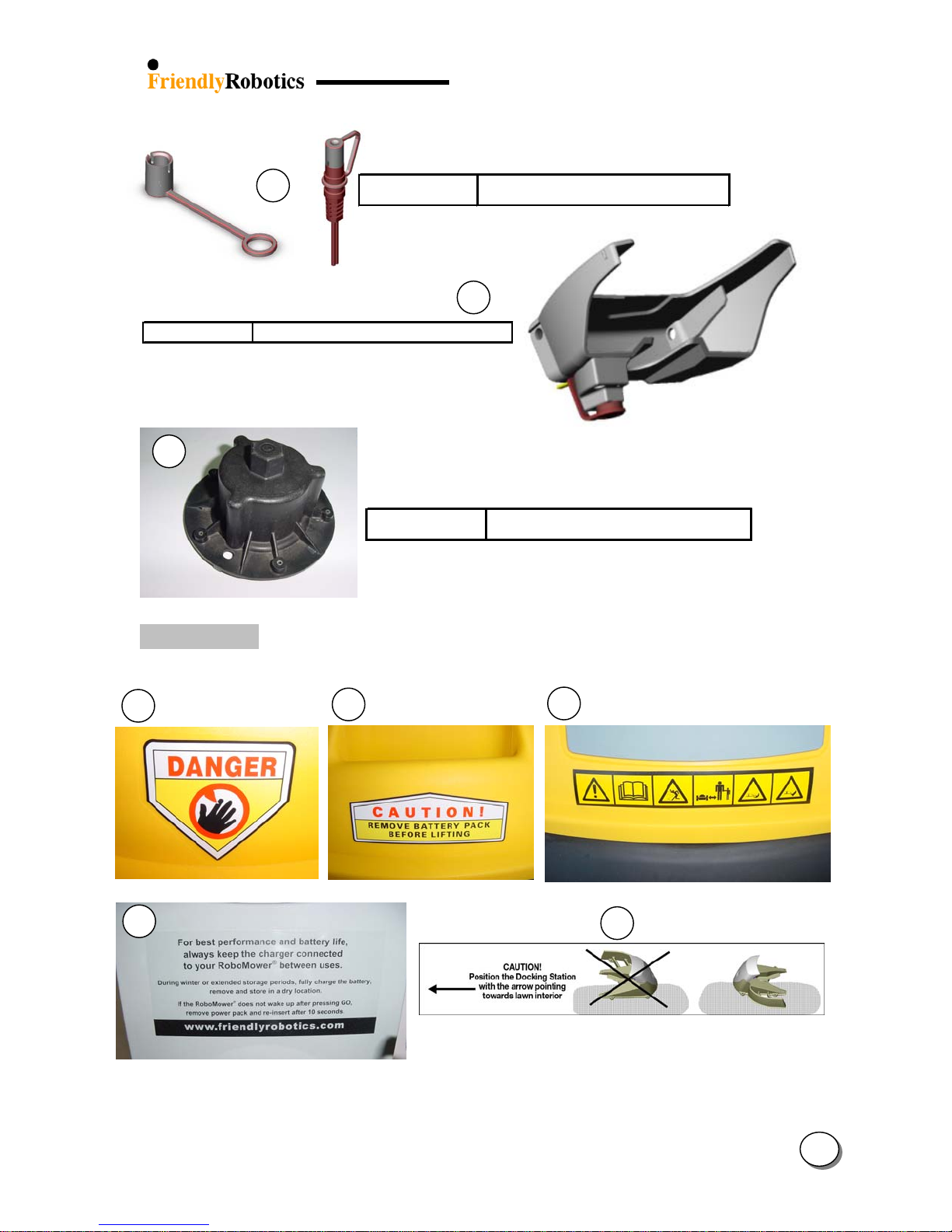
1.2.13 Decals
89
90
26
91
92
93
1
17
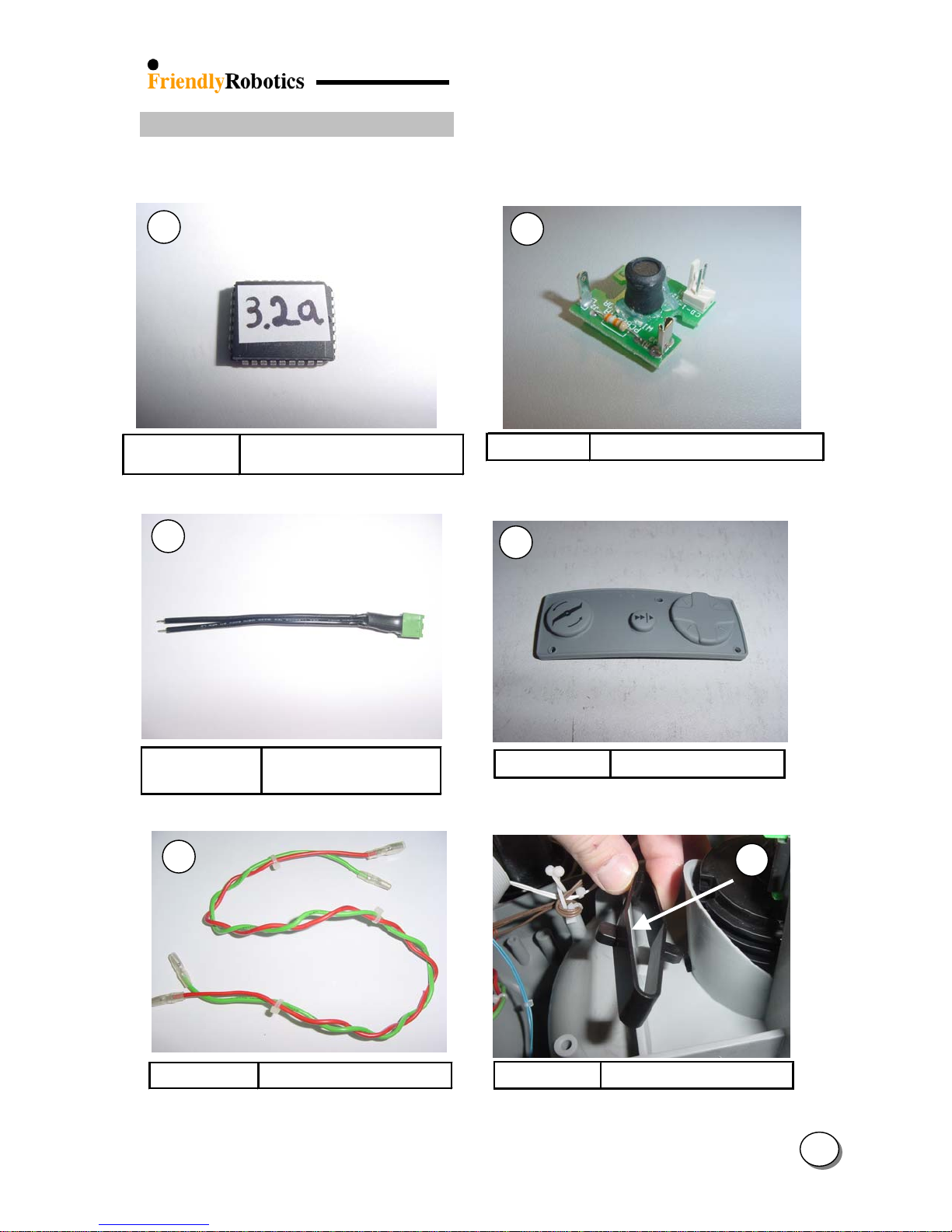
1.2.14 Old configuration spare parts
The parts below are available spare parts, which are not part of the ’05 configuration, but are
still required to support the previous RL configurations.
94
95
SPP0027A
96
WSB0025B
98
Flash Software v 3.2a (Main
Board ESB0019)
Perimeter wire to
perim. switch cable
ESB0031A Rear Right Wire Sensor Board
97
GEN0148A Navigator keypad
99
WSB0053A Mowing motors cable
1
GEN0118A Front Wheel Click Spring
18
(-)
(+)
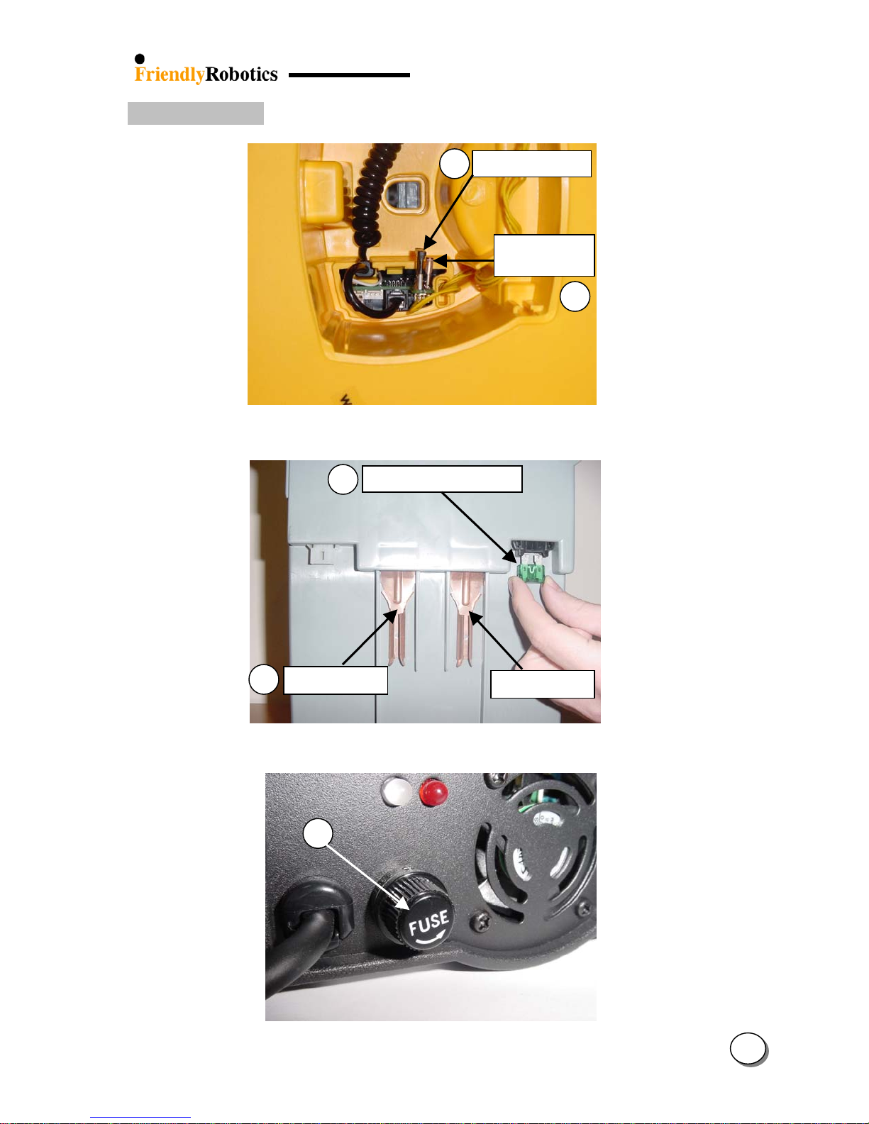
1.3 Fuse location
72
1A Lamp fuse
5A Charging
70
Figure 1.3.1 Robomow fuse location
71
30A Power Pack fuse
64
Terminal
Terminal
Figure 1.3.2 Power Pack fuse location
69
Figure 1.3.3 External Charger fuse location
1
19
T
–
1.4 Board identification
1.4.1 Main Board
104
12
he Mowing motor cable is available
as a separate part to support old
12 - Soldered to the mowing motor
configuration models.
Only cable
98
1.4.2 Connector Board
12
100 101
12
43
103
102
25
21
17
82
1
20
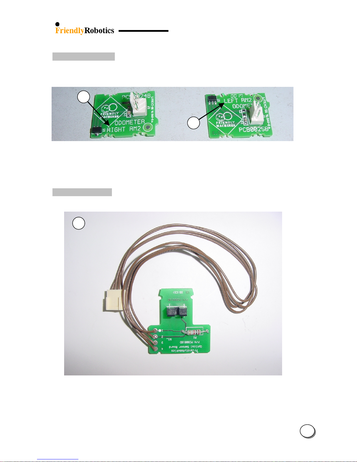
1.4.3 Odometer Board
19
Right odometer board Left odometer board
1.4.4 Drop-off Board
82
24
1
21
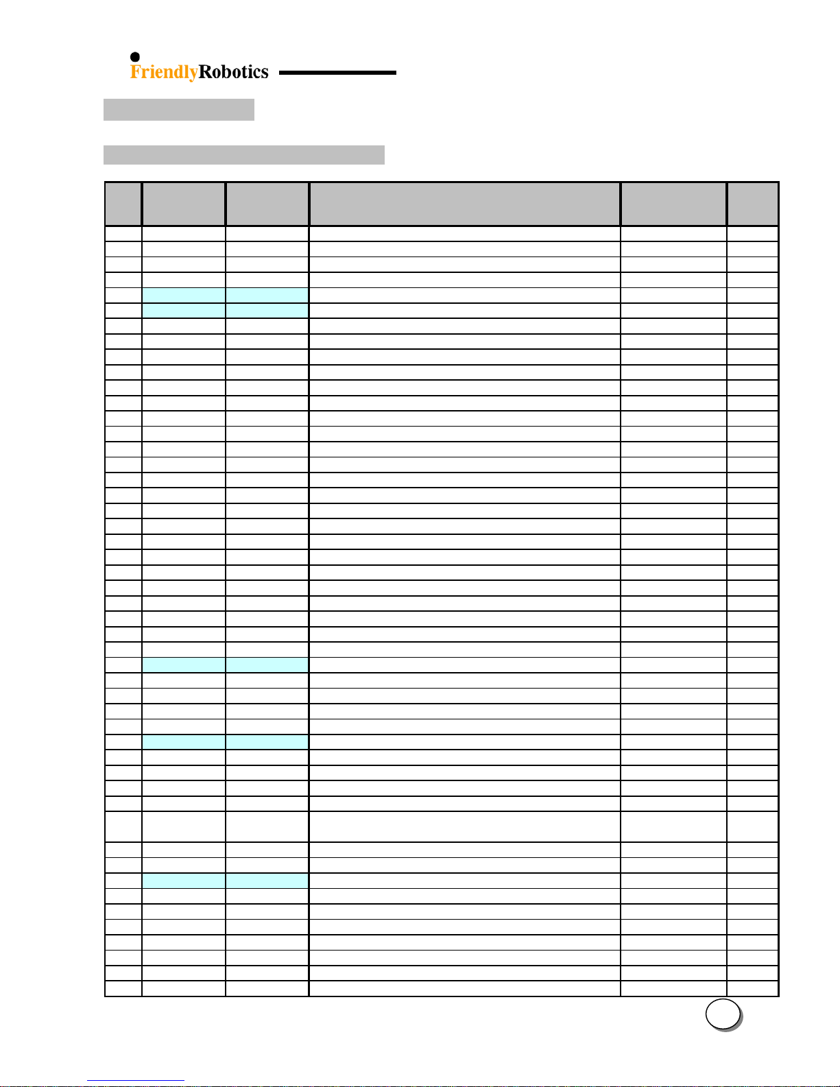
1.5 Wiring layout
1.5.1 Robomow schematic wiring diagram
109
1
22

1.5.2 Power Pack wiring diagram
Fuse holder & cable (Red)
+
+-++
-
--
+
+-++
-
--
108
Fuse holder & cable (Red)
WSB0046B
WSB0046B
Battery jumper cable
Battery jumper cable
WSB0049B
WSB0049B
Grey
Grey
Negative battery cable (Black)
Negative battery cable (Black)
WSB0048B
WSB0048B
107
106
Red
Red
Red
Red
Fuse
Fuse
Fuse
Holder
Holder
Holder
Battery
Battery
Battery
Contact
Contact
Contact
Left (+)
Left (+)
Left (+)
Battery
Battery
Battery
Contact
Contact
Contact
Right (+)
Right (+)
Right (+)
1
23
y
y
)
g
g
y
)
)
ging
)
g
)
g
y
ging
1.6 Spare Parts List
1.6.1 Spare Parts – sorted by item number
Friendly P/N
#
1 GEN0094A GEN0094A RL Yellow cover
1 GEN0227A GEN0227A RL Green cover
2 MSB0112A MSB0112A Manual controller- Europe (tones)
2 MSB0114A MSB0114A Manual Controller - US
2 MSB0118A MSB0117A Manual controller (ESBC050B and forwards)
2 MSB0119A -------- Enhanced Manual Controller
3 MSB0078A MSB0078A Smooth drive wheel + bearing
3 MSB0099A MSB0099A Knobby drive wheel + bearing
4 UNT0009A UNT0009A Power Pack
5 MSB0107A MSB0107A Rear bumper assembl
6 SPP0032A SPP0032A operation lamp cover + seal 1.1.1 & 1.2.3 1
7 MSB0105B MSB0105B Man. cont. holder assembl
8 STC0048A STC0048A RL550 Sticker
8 STC0049A STC0049A RL850 Sticker
8 STC0051A STC0051A RL800 Sticker
8 STC0056A STC0056A RL1000 Sticker
8 STC0057A STC0057A RL350 Sticker
9 SPP0026A SPP0026A Charging contact (for Docking Station) + screws
10 MSB0106B MSB0106B Front bumper (one spring) assembly
11 SPP0011A SPP0011A Front wheel with axle
12 MSB0065B MSB0065B Mowing Unit + cable
13 GEN0095A GEN0095A RL plastic base
14 GEN0162A GEN0162A Snap lock (straight)
15 SPP0012A SPP0012A Sin
15 SPP0013A SPP0013A Sin
16 GEN0163A GEN0163A Snap lock (curved)
17 SPP0018A SPP0018A Wire Sensors x4 with cable (+DOC0057A)
18 GEN0182A GEN0182A Cover-base seal ring
19 ESBC024C ESBC024B Odometer Board R
20 SPP0014A SPP0014A Batter
21 SPP0020A SPP0020A Thermistors kit
22 GEN0202A GEN0202A Ground clearance limiter
23 SPP0008B SPP0008B Drive motor replacement kit
24 ESBC025C ESBC025B Odometer Board L
25 SPP0019B SPP0019B Main Board (ESBC050B)
26 GEN0210A GEN0210A Charging socket rubber cover
27 GEN0208A GEN0208A Front Wheel stopper spring
28 GEN0207A GEN0207A Front Wheel stopper
29 SPP0030A SPP0030A
30 SPP0029A SPP0029A Charging Station Base (Yellow)
30 SPP0039A SPP0039A Char
31 GEN0215C GEN0215B Dockin
32 SPP0031A SPP0031A Dockin
33 STC0054A STC0054A Char
34 GEN0140A GEN0140A Sealing cup
35 ESB0022B ESB0022B Lamp Board
36 GEN0133A GEN0133A Magnet for Manual Controller
37 RNG0005A RNG0005A Spacer for Drive Wheel - D18*D12*0.5 DIN 988
38 RNG0002A RNG0002A Retaining ring for 12mm shaft (for Drive Wheel)
(2006)
Friendly P/N
(2005)
Part Description
(sp
le high cut blade
le low cut blade
contacts assembly (RL side
Charging Station Cover (includes lexan, screws, sticker
and push button
Station Base (Green
Station Fence (Green
Station Contacts Assembl
station cover sticker
Appears in
Exploded views
No.
1.1.1 1
1.1.1 1
1.1.1 & 1.2.3 1
1.1.1 & 1.2.3 1
1.1.1 & 1.2.3 1
1.1.1 & 1.2.3 1
1.1.1 & 1.2.1 2
1.1.2 2
1.1.1 & 1.2.6 1
1.2.8 1
1.1.1 & 1.2.3 1
1.1.1 1
1.1.1 1
1.1.1 1
1.1.1 1
1.1.1 1
1.1.1 & 1.2.3 1
1.2.8 1
1.1.2 & 1.2.10 1
1.2.1 & 1.1.3 3
1.1.2 1
1.1.2 6
1.1.2 & 1.2.11 3
1.1.2 & 1.2.11 3
1.1.2 4
1.1.3 1
1.2.2 1
1.1.3 & 1.4.3 1
1.1.3 & 1.2.2 2
1.1.3 & 1.2.11 1
1.1.3 & 1.2.5 1
1.1.3 & 1.2.5 2
1.1.3 & 1.4.3 1
1.1.3 & 1.4.1 1
1.2.12 1
1.2.2 & 1.1.3 2
1.2.2 & 1.1.3 1
1.2.4 1
1.2.4 1
1.2.4 1
1.2.4 1
1.2.4 1
1.1.4 1
1.2.1 4
1.2.1 1
1.2.1 1
1.2.1 2 to 8
1.2.1 2
1
No. of
parts
24
(
)
)
(
)
g
g
(
)
(
g
)
g
y
y
)
y
)
g
g
(
)
(
)
1.6.1 Spare Parts – sorted by item number (con.)
Friendly P/N
#
39 GEN0104A GEN0104A Wheel Cup (gray)
39 GEN0201A GEN0201A Wheel Cup (black)
40 GEN0146A GEN0146A Main board rubber holder
41 CPS0007A CPS0007A Wire twist lock
42 GEN0171A GEN0171A Motor shading
43 ESBC021C ESBC021C Connectors Board
44 SPP0004C SPP0004B Spare part gear case
45 GEN0142A GEN0142A Connector's cover
46 GEN0145A GEN0145A Pivot for manual controller's tray
47 LMP0004A LMP0004A Operating bulb bayonet 24v/4w
48 SCR0029A SCR0029A Screw DIN 7981C A2 4.2x25
49 SPP0028B SPP0028A
50 SCR0027A SCR0027A Screw WN 1412 KA25x8
51 GEN0176A GEN0176A Dockin
52 GEN0218A GEN0218A Push button for Dockin
53 GEN0223A GEN0223A Fastening Stakes for the Charging Station
54 GEN0217B GEN0217B D. Station Connectors Cover
55 SPP0009B SPP0009A Gear Shafts replacement kit
56 SPP0015A SPP0015A Gear Frame (+ GEN0202A and DOC0056A)
57 GEN0122A GEN0122A Shafts clamp
58 MSB0077A MSB0077A Slider assembly
59 MSB0079A MSB0079A Gear spline + bearing
60 GEN0101A GEN0101A Odometer ma
61 SCR0025A SCR0025A Screw for RL motors
62 GEN0132A GEN0132A Battery cover
63 GEN0131A GEN0131A Batter
64 GEN0130A GEN0130A Contact leaf-battery
65 PWS0004A PWS0004A 230VAC Out Door Power Supply (EUR)
65 PWS0005A PWS0005A 115VAC Out Door Power Suppl
65 PWS0006A PWS0006A 230VAC Out Door Power Suppl
66 PWS0001A PWS0001A 230VAC power supply -Europe
66 PWS0002A PWS0002A 230VAC power supply - UK
66 PWS0003A PWS0003A 115VAC power supply - US
67 CBL0037A CBL0037A External charger cord - UK
67 CBL0038A CBL0038A External char
67 CBL0039A CBL0039A External char
68 UNT0016A UNT0016A Power Pack external charging adaptor
69 FUS0021A FUS0021A Fuse 5x20 10A 125V
70 FUS0015A FUS0015A Fuse mini blade 5A
71 FUS0003A FUS0003A Fuse AT blade 30A 32V
72 FUS0012A FUS0012A Fuse AT blade 1A 32V
73 MRK0025B MRK0025B 5 hrs. Perimeter Switch
74 GEN0156A GEN0156A Perimeter switch back cover
75 GEN0175A GEN0175A Stake for perimeter switch
76
77 CON0054A CON0054A Plot connector
78 MSB0090A MSB0090A Contact strip front assembly
79 MSB0091B MSB0091B Contact strip rear assembly
80 RNG0031A RNG0030A Washer M10x15
81 GEN0117A GEN0117A Adjusting bolt
82 SPP0005B SPP0005B Drop off board + holder 1.2.10 1
(2006)
BAT0003A BAT0003A Battery holder for perim.switch with screws 1.2.8 1
Friendly P/N
(2005)
Part Description
Docking Station
Charging Station Board (includes screws, tact switch
cover and push button
Docking Board
Board seal
Board
Green
ear
net
Case
(US
(UK
er cord - US
er cord - EUR
External Charger
BN 739
Appears in
Exploded views
No.
1.2.1 2
1.1.3 & 1.2.1 2
1.2.2 4
1.2.2
1.2.2 5
1.2.2 & 1.4.2 1
1.2.2 & 1.2.5 1
1.2.3 1
1.2.3 2
1.2.3 1
1.2.4 5
1.2.4 1
1.2.4 8
1.2.4 1
1.2.4 1
1.2.4 5
1.2.4 3
1.2.5 1
1.2.5 1
1.2.5 2
1.2.5 2
1.2.5 2
1.2.5 4
1.2.5 8
1.2.6 1
1.2.6 1
1.2.6 2
1.2.6 1
1.2.6 1
1.2.6 1
1.2.6 1
1.2.6 1
1.2.6 1
1.2.6 1
1.2.6 1
1.2.6 1
1.2.6 1
1.2.7 & 1.3 1
1.2.7 & 1.3 1
1.2.7 & 1.3 1
1.2.7 & 1.3 1
1.2.8 1
1.2.8 1
1.2.8 1
1.2.8 1
1.2.8 1
1.2.8 1
1.2.10 1
1.2.10 1
No. of
parts
1
25
ging
g
)
g
)
g
)
g
)
1.6.1 Spare Parts – sorted by item number (con.)
Friendly P/N
#
83 GEN0116A GEN0116A Drop off flag
84 NIT0009A NIT0009A Pop rivet/D3.2x6 (Thermistors)
85 HSN0003A HSN0003A Heat sink silicone insulator (Thermistors)
86 DOC0015D DOC0015C RL Operating Manual (En)
86 DOC0076B DOC0076A RL1000 + Docking Manual (En)
87 GEN0211A GEN0211A charging plug rubber cover
88 TOL0001A TOL0001A Mowing motor removal tool
89 STC0018A STC0018A Danger sticker
90 STC0022A STC0022A Front caution sticker
91 STC0012A STC0012A Rear warning sticker
92 STC0036B STC0036B Battery charging decal (En)
93 STC0055A STC0055A Charging Station fence sticker
94 SPP0027A SPP0027A Flash Software v3.2a+ (ESB0019C)
95 ESB0031A ESB0031A Rear Right Wire Sensor Board (old configuration)
96 WSB0025B WSB0025B Perim. wire to perim. switch cable
97 GEN0148A GEN0148A Navigator keypad
98 WSB0053A WSB0053A Mowing motors cable
99 GEN0118A GEN0118A Front Wheel Click Spring ('02 configuration)
100 WSB0035A WSB0035A Main board to battery cable
101 WSB0052A WSB0052A Flat cable
102 WSB0041A WSB0041A Odometers cable
103 WSB0043B WSB0043B Bumper cable
104 WSB0063A WSB0063A Drive motor + ferrite cable
105 WSB0044A WSB0044A Lamp board cable
106 WSB0046B WSB0046A Fuse holder battery pack cable
107 WSB0048B WSB0048A (-) spring battery cable
108 WSB0049B WSB0049A Battery jumper cable
109 WSB0070A WSB0070A Connector Board to char
110 DOC0008B DOC0008B RoboRuler
111 DOC0051E DOC0051D RL Service Guide Hard Copy (En)
112 DOC0053C DOC0053B RL Service Guide CD (En)
113 DOC0065B --------- RL Operating & Safety CD (En)
114 PRG0005A PRG0005A Flash Software v3.2i (Service version - 03 models)
115 SPP0033C SPP0033B Flash Software v3.2-06 + Operating Manual (En)
115 SPP0035C SPP0035B Flash Software v3.2-06 + Operating Manual (BLX)
115 SPP0036C SPP0036B Flash Software v3.2-06 + Operating Manual (DE)
115 SPP0040C -------- Flash Software v3.2-06 + Operating Manual (IT)
115 SPP0041C -------- Flash Software v3.2-06 + Operating Manual (DK)
115 SPP0101A -------- Flash Software v4.1-06 + Operatin
115 SPP0102A -------- Flash Software v4.1-06 + Operatin
115 SPP0103A -------- Flash Software v4.1-06 + Operatin
115 SPP0104A -------- Flash Software v4.1-06 + Operatin
115 SPP0105A -------- Flash Software v4.1-06 + Operating Manual (DK)
116 CPS0013A CPS0013A Wire twist lock for bat. cable
120 STC0052A STC0052A Theft Guard decal
121 GEN0067A GEN0067A Fast charger 115/230V (without cord)
122
123
124 STC0058A ------- Crossed-out wheeled bin
125
126
127 SCR0033A -------- Screw for the Charging Station drive wheel supports
(2006)
GEN0229A
GEN0230A
GEN0231A
CPS0014A
Friendly P/N
(2005)
--------
--------
--------
--------
Part Description
contacts cable
Manual (En
Manual (BLX
Manual (DE
Manual (IT
Charging Station right wheel support 1.1.4 & 1.2.4 1
Charging Station left wheel support 1.1.4 & 1.2.4 1
Gear frame support
Plastic rivet (between cover and base)
Appears in
Exploded views
No.
1.2.10 1
1.2.11 2
1.2.11 2
1.2.12 1
1.2.12 1
1.2.12 1
1.1.12 1
1.2.13 2
1.2.13 1
1.2.13 1
1.2.13 1
1.2.13 1
1.2.14 1
1.2.14 1
1.2.14 1
1.2.14 1
1.2.14 & 1.4.1 3
1.2.14 1
1.4.1 & 1.5.1 1
1.4.1 & 1.5.1 1
1.4.1 & 1.5.1 1
1.4.1 & 1.5.1 1
1.4.1 & 1.5.1 1
1.2.3 & 1.5.1 1
1.5.2 1
1.5.2 1
1.5.2 1
1.5.1 1
NA 1
NA
NA
NA
NA
NA
NA
NA
NA
NA
NA
NA
NA
NA
NA
NA
NA
1.2.6
1.2.4 2
No. of
parts
1
1
1
26
g
g
g
x
)
g
)
g
g
j
(
g
)
y
y
g
1.6.2 Spare Parts – sorted by Friendly part number
76
67 CBL0037A CBL0037A External char
67 CBL0038A CBL0038A External char
67 CBL0039A CBL0039A External char
77 CON0054A CON0054A Plot connector
41 CPS0007A CPS0007A Wire twist lock
116 CPS0013A CPS0013A Wire twist lock for bat. cable
126
110 DOC0008B DOC0008B RoboRuler
86 DOC0015D DOC0015C RL Operating Manual (En)
111 DOC0051E DOC0051D RL Service Guide Hard Copy (En)
112 DOC0053C DOC0053B RL Service Guide CD (En)
113 DOC0065B --------- RL Operating & Safety CD (En)
86 DOC0076B DOC0076A RL1000 + Docking Manual (En)
35 ESB0022B ESB0022B Lamp Board
95 ESB0031A ESB0031A Rear Right Wire Sensor Board (old configuration)
43 ESBC021C ESBC021C Connectors Board
19 ESBC024C ESBC024B Odometer Board R
24 ESBC025C ESBC025B Odometer Board L
71 FUS0003A FUS0003A Fuse AT blade 30A 32V
72 FUS0012A FUS0012A Fuse AT blade 1A 32V
70 FUS0015A FUS0015A Fuse mini blade 5A
69 FUS0021A FUS0021A Fuse 5
121 GEN0067A GEN0067A Fast char
1 GEN0094A GEN0094A RL Yellow cover
13 GEN0095A GEN0095A RL plastic base
60 GEN0101A GEN0101A Odometer ma
39 GEN0104A GEN0104A Wheel Cup (gray)
83 GEN0116A GEN0116A Drop off fla
81 GEN0117A GEN0117A Ad
99 GEN0118A GEN0118A Front Wheel Click Spring ('02 configuration)
57 GEN0122A GEN0122A Shafts clamp
64 GEN0130A GEN0130A Contact leaf-battery
63 GEN0131A GEN0131A Batter
62 GEN0132A GEN0132A Batter
36 GEN0133A GEN0133A Magnet for Manual Controller
34 GEN0140A GEN0140A Sealing cup
45 GEN0142A GEN0142A Connector's cover
46 GEN0145A GEN0145A Pivot for manual controller's tray
40 GEN0146A GEN0146A Main board rubber holder
97 GEN0148A GEN0148A Navigator keypad
74 GEN0156A GEN0156A Perimeter switch back cover
14 GEN0162A GEN0162A Snap lock (straight)
16 GEN0163A GEN0163A Snap lock (curved)
42 GEN0171A GEN0171A Motor shading
75 GEN0175A GEN0175A Stake for perimeter switch
51 GEN0176A GEN0176A Dockin
18 GEN0182A GEN0182A Cover-base seal ring
39 GEN0201A GEN0201A Wheel Cup (black)
22 GEN0202A GEN0202A Ground clearance limiter
28 GEN0207A GEN0207A Front Wheel stopper
27 GEN0208A GEN0208A Front Wheel stopper spring
26 GEN0210A GEN0210A Charging socket rubber cover
87 GEN0211A GEN0211A Charging plug rubber cover
(2006)
BAT0003A BAT0003A Battery holder for perim.switch with screws 1.2.8 1
CPS0014A
Friendly P/N
#
Friendly P/N
(2005)
--------
Part Description
er cord - UK
er cord - US
er cord - EUR
Plastic rivet (between cover and base)
20 10A 125V (External Charger
er 115/230V (without cord
net
usting bolt
ear
Case
cover
Board seal
Exploded views
1
Appears in
No.
1.2.6 1
1.2.6 1
1.2.6 1
1.2.8 1
1.2.2
NA
NA 1
1.2.12 1
NA
NA
NA
1.2.12 1
1.2.1 1
1.2.14 1
1.2.2 & 1.4.2 1
1.1.3 & 1.4.3 1
1.1.3 & 1.4.3 1
1.2.7 & 1.3 1
1.2.7 & 1.3 1
1.2.7 & 1.3 1
1.2.7 & 1.3 1
1.2.6
1.1.1 1
1.1.2 1
1.2.5 4
1.2.1 2
1.2.10 1
1.2.10 1
1.2.14 1
1.2.5 2
1.2.6 2
1.2.6 1
1.2.6 1
1.2.1 1
1.2.1 4
1.2.3 1
1.2.3 2
1.2.2 4
1.2.14 1
1.2.8 1
1.1.2 6
1.1.2 4
1.2.2 5
1.2.8 1
1.2.4 1
1.2.2 1
1.1.3 & 1.2.1 2
1.1.3 & 1.2.5 1
1.2.2 & 1.1.3 1
1.2.2 & 1.1.3 2
1.2.12 1
1.2.12 1
No. of
parts
27
1
 Loading...