

Friendly Robotics RL500, RL550, RL800, RL850, Robomower RL500 Operating & Safety Manual
...
F
F
F
r
r
r
i
i
i
e
e
e
n
n
n
d
d
d
l
l
l
y
y
y
R
R
R
o
o
o
b
b
b
o
o
o
t
t
t
i
i
i
c
c
c
s
s
s
Operating & Safety Manual
Robomower
RL500 / RL550
RL800 / RL850
www.friendlyrobotics.com
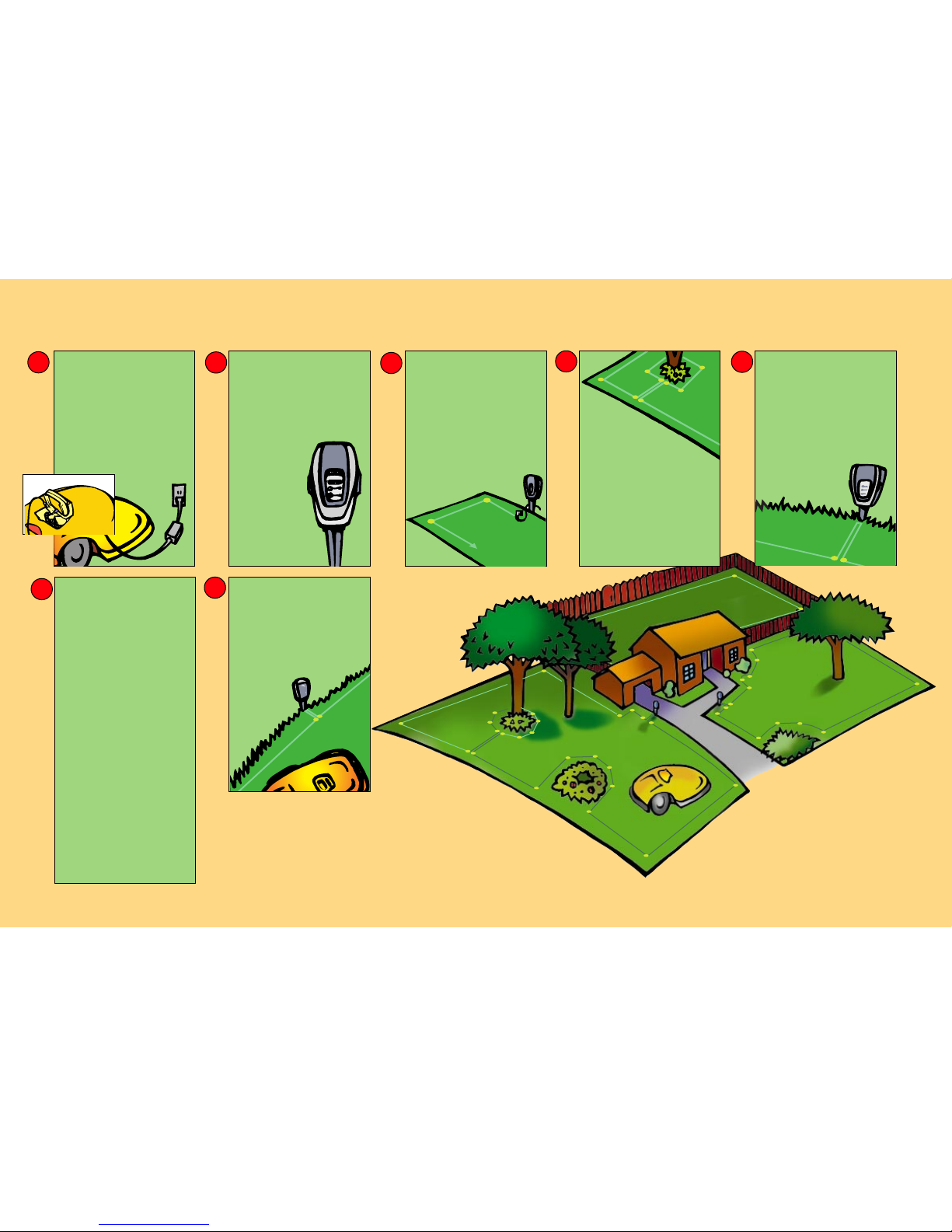
QuickStart Reference Guide
3
4
2
␣5
6
␣7
CHARGE THE UNIT
• Raise wheels to highest setting.
• To raise rear wheel, move adjustment
setting handle located in the rear
battery pack compartment, to its
lowest setting.
• To raise front wheel, rotate front
wheelbase- each “click” represents
one notch of height.
• Insert fuse, place battery pack in unit.
• Plug charger into wall unit.
• Plug charger into manual controller
base plug.
PERIMETER SWITCH
• Open perimeter switch cover.
• Install three (3) C batteries.
• Close perimeter switch cover.
• Install on perimeter switch stake.
(After laying the perimeter around
your designated plots, you will
attach the ends to the green switch
connectors to close the perimeter
loop.)
• Mount vertically in
ground, at least 5
feet from the
perimeter wire.
INSTALL PERIMETER
WIRE
• Lay the wire around lawn edge and
peg down tight.
• Use ruler for appropriate spacing on
all wire installation.
• Narrow areas, less than 5.5 ft. wide
and obstacles closer than 4 ft. from
lawn edges should be left out of the
installed area.
(Helpful hint: Peg the wire at each corner.
Fill back in with additional pegs where the
wire is loose or raised above the
ground.)
PROTECTING
FLOWERBEDS AND
OTHER OBJECTS
• Wire around any area you don’t want
␣
the mower to enter: around trees, flower
beds, ponds, swimming pool, young
trees, holes and ditches etc.
• The two wires leading from the edge to
the protected area and back must be
parallel, touching and pegged down
side-by-side.
• The mower’s bumper will recognize trees
␣ ␣
and solid obstacles higher than 6 inches.
No need to protect them with a wire.
(Helpful hint: Use Roboruler provided for proper
spacing around obstacles)
COMPLETING THE LOOP
• After completing your wire installation:
• The wires leading to the perimeter
switch should be parellel, touching and
pegged tightly to the ground.
• Make sure the perimeter switch and
wires leading to it are at least 5 ft.
from the perimeter wire.
• Strip 1/4 in. of plastic from the wire
ends and insert into the green switch
connector (one wire per hole).
• Tighten screws.
• Press the green “On”
button on the perimeter
switch.
INITIAL SETTINGS
• Place the mower inside the lawn
perimeter on level ground.
• FOR FIRST OPERATION ONLY:
• Press the "GO" button. The display will
read “Warming Up” and then “Set
Country”.
• Press the "GO" button again. The
display should read, ‘Not Set!’
• Scroll to your country and press the
"GO" button.
• Press the “GO” button once again.
'Calibration Req' message will appear.
Press "GO" once more.
'Activate Motors' message will appear.
Press "GO" to activate calibration.
• The Robomower will rotate through
several circles while the calibration
process is occuring, pausing for several
seconds at various points in the circle.
When complete, the message 'Test
Passed - Press C' will display. Press the
'C' button four (4) times.
START MOWING
• Position your robomower inside the
perimeter wire at least four (4) feet
from the wire and not aimed at a
corner.
• Make sure perimeter switch is on
and press the"GO“ button.
IT MOWS. YOU DON’T.
• After mowing, recharge your
battery.
1
For product service please
contact your service dealer
or visit us on the web at
www.friendlyrobotics.com
US customers 1-888-404-7626 (ROBO)

Chapter 1
Page 10
FriendlyRobotics
•
FriendlyRobotics, 2002. All rights reserved. No part of this document may be
photocopied, reproduced, electronically or otherwise or translated without the prior
•
written consent of FriendlyRobotics.
Product, product specifications and this document are subject to change without notice.
All other trademarks are the property of their respective owners.
CE approved
Welcome
Page 2
FriendlyRobotics
Welcome…
To the world of robotic lawn mowing with the Friendly Robotics Robomower. Thank you
for purchasing our product. We know that you will enjoy the extra free time you will have while
using Robomower to mow your lawn. When installed and used properly, Robomower will
operate safely on your lawn and provide you with a quality of cut matched by few mowers of any
kind. You will be impressed with your lawns’ appearance and best of all Robomower did it for
you.
IMPORTANT!
The following pages contain important safety and operating instructions. Please
read and follow all instructions in this manual. Carefully read and review all
safety instructions, warnings and cautions contained in this manual. Failure to
read and follow these instructions, warnings and cautionary statements may
result in severe injury or death to persons and pets or damage to personal
property.
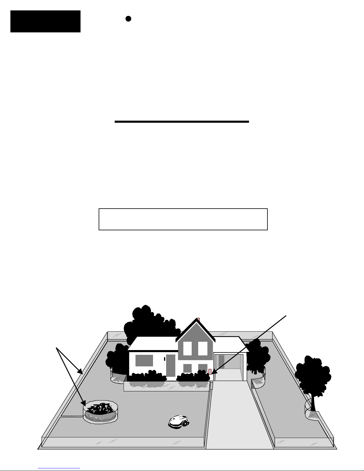
A small wire, called the perimeter wire, is placed around the perimeter of the lawn and any other areas
where you do not want the mower to enter. A small signal is generated from a device attached to the
perimeter wire, called the Perimeter Switch. When turned on, this signal is carried through the perimeter
wire, creating what we define as a virtual wall. The virtual wall is visible only to the Robomower, keeping
the Robomower where you want it, on your lawn. The perimeter switch must be turned on to activate the
A Basic How It Works
perimeter wire before the Robomower will operate.
Perimeter switch turned
on to generate signal
Virtual wall, visible
only to the
Robomower.

Safety Warnings & Precautions
1. Read the owners/operating manual carefully and follow all safety
and warning instructions.
2. Keep bystanders, children and pets away from mower when in
operation.
3. Never allow anyone to ride or sit on mower.
4. Never allow children or persons not familiar with the safe
operation of the mower to operate the mower.
5. Keep hands and feet away from the cutting blades and other
moving parts.
6. Never attempt to service or adjust the mower while it is in
operation.
7. Inspect and clear the mowing area of all debris before operating
the mower.
8. Never raise the mower or attempt to inspect the blades while the
mower is operating.
9. Always remove the power pack before lifting the mower or
attempting any adjustments.
10. When operating the mower in manual mode, maintain a safe
distance from behind or around the mower and wear proper foot
apparel.
11. Do not operate the mower on slopes greater than 15 degrees or
use it in manual operation on slopes where a firm footing is not
possible.
12. Do not operate the mower if any safety feature or device is
damaged or inoperable.
13. Do not attempt to disable or defeat any safety feature or device.
14. Use heavy gloves when inspecting or servicing the blades.
15. The charger is for indoor use only. Do not use in areas where
moisture or water is likely.
16. Wear eye protection and use gloves when installing the
perimeter wire and driving the wire stakes/pegs.
SAFETY
Page 3
SAFETY
Page 4
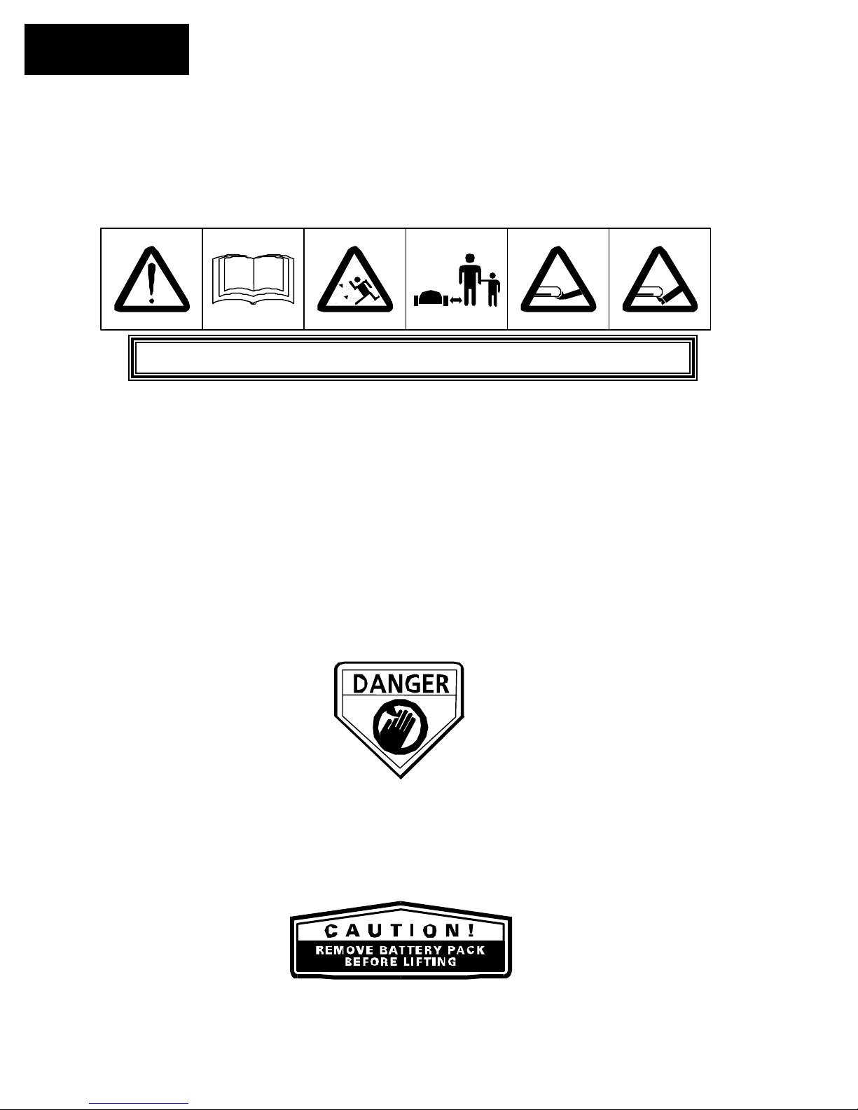
Safety Warnings & Precautions
Warning Decal Definitions
1
1. WARNING-this is a dangerous power tool. Use care when operating and
follow all safety instructions and warnings.
2. Read the owner/operating manually carefully and follow all safety
instructions.
3. Objects can be thrown from mower while operating, take caution.
4. Keep children, pets and bystanders away from mower.
5. Sharp rotating blades. Keep hands away and do not attempt to lift mower
from this area.
6. Sharp rotating blades. Keep feet away.
DANGER! Sharp rotating blades. Keep hands and feet away.
CAUTION! Remove battery/power pack before
attempting to lift mower for any reason.
2
3 4 5 6
Serious injury can occur.

Robomower RL500/RL550/RL800/RL850
Safety Features
1. Child Guard / Safety Guard
This menu option offers a safety feature to help prevent children or others not familiar with the
safe operation of the mower to operate it freely.
2. Lift Sensor
There is a sensor located on the front caster wheel of the mower. In the event the front of the
mower is raised approximately 1-inch from its resting position on the ground during blade
operation, the blades will stop rotating immediately (< 1 second).
3. Sensor Equipped Bumpers
The front and rear bumpers are equipped with contacts that will activate when the mower strikes
a solid, fixed object when that object is at least 6-inches in vertical height from the supporting
surface of the mower. When the bumper sensor is activated, the mower will stop movement in
that direction and reverse itself away from the obstacle. In manual blade operation, bumper
activation will stop the rotation of the blades immediately (<1 second).
4. Emergency Stop Switch
Located on the top outer surface of the manual controller, red in color. Pressing this button at
any time during operation will stop all mower movement and stop the rotation of the blades
immediately (<1 second).
5. Automatic Mode Recognition
The Robomower is designed so that it cannot be operated in the manual mode while the Manual
Controller is in its’ pocket and it cannot operate in the automatic mode while the Manual
Controller is removed.
6. Two-Step Operator Presence Control
While in manual mode, it requires two independent finger actions in order to engage the mower
blades. Once engaged, the mower blade button must remain depressed to continue blade
operation. Once released, the two-step engagement process must be repeated.
7. Electronically Controlled Charging System
The Robomower is equipped with an on-board charge control system. This allows you to keep
the charger connected at all times, even after the battery is fully charged. The control system will
prevent an overcharge to the battery and keep it fully charged and maintained for the next use.
8. Sealed Power Pack
The power pack that operates the Robomower is completely sealed and will not leak any type of
fluids, regardless of position. In addition, the power pack contains a one-time-use fuse in the
event of a short-circuit or power malfunction.
SAFETY
Page 5

SAFETY
Page 6
9. Perimeter Switch and Perimeter Wire
The Robomower cannot operate without a perimeter wire installed and activated through the
Perimeter Switch. In the event the Perimeter Switch is turned off or otherwise fails to function, the
Robomower will stop operating. Likewise, should a break in the perimeter wire occur the Robomower
would again stop operation. A break in the perimeter wire prior to operation will prevent the
Robomower from operating. The Robomower can only operate within the boundary of the perimeter
wire.
10. Auto-Off Perimeter Switch
The auto-off feature of the perimeter switch shuts down the perimeter switch operation after
approximately 5 hours of continuous operation. This is typically 1 to 2 hours after which a fully
charged Power Pack will need to be re-charged. This helps to prevent unauthorized persons from
attempting to re-start the Robomower after it has completed its’ operation.
11. Over-Current Monitoring Protection
Each of the three blade motors and each of the two wheel drive motors are monitored continuously
during operation for any situation that may cause these motors to over-heat. In the event this is
detected, the Robomower will stop operation of at least that motor and possibly the mower itself and
indicate that the motor is cooling down. While unusual, this may happen when the mower is put in
grass that is severely overgrown; the underside of the mower is clogged from poor cleaning
maintenance; the mower has encountered an obstacle that is unable to activate the bumper sensor
preventing it from moving; or a problem landscape area has caused the mower to get stuck and is
preventing it from moving.
WARNING!
!
This warning symbol will be found at several points throughout the
pages of this owner/operator manual. It is intended to highlight an
important safety, warning or cautionary message. Please pay
particular attention to these areas and be sure you fully understand
the message before proceeding.
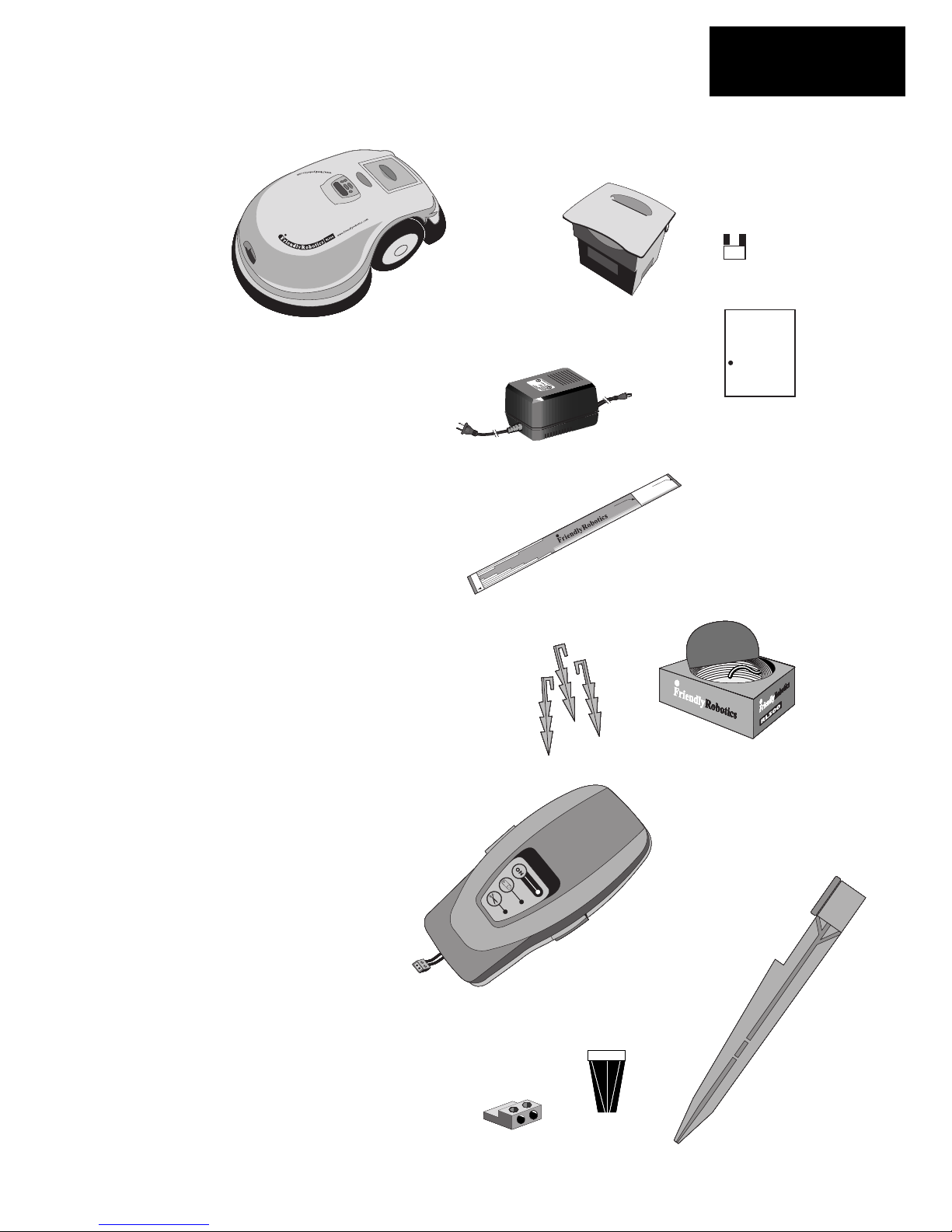
1. Standard Charger
Used for recharging the Robomower
3 . Pegs
2. RoboRuler
Used for setting the distance of the
perimeter wire from the lawn edge.
4.
Used for securing the perimeter wire to
the ground around the lawn perimeter
5.
Wire
Used to create a virtual wall for your
Robomower
6
.
Perimeter Switch & C-Cell Batteries
Activates the perimeter wire, which
defines the area in which the
Robomower will operate.
7
.
Perimeter Switch Mounting Stake
Used for supporting the perimeter
switch in the lawn.
8
.
Wire Connectors
Used for splicing wires (as needed).
Plot Connectors
Used for connecting the completed
NOTE: Installation tools needed, but not
included: hammer, wire cutters, small flathead screwdriver.
Robomower
What's in the Box
Power Pack
1.
2.
3.
4.
5.
6.
7.
8.
FUSE
Power Pack Fuse
(Must insert to operate)
Owner/Operator
FriendlyRobotics
Operator/Owner Manual
power pack.
and around obstacles.
perimeter wire installation to the
perimeter switch.
Manual
Robomower
Rl500/RL800
Whats In The Box
Page 7

Table of Contents
Page 8
Welcome, Basic How It Work ………………………………………………..2
The world of robotic mowing with the Robomower
Safety Warnings and Precautions…………………………………………….3
Safely operating the Robomower
What’s In The Box………………………………………………………………..7
A list and descriptions of the items found in the Robomower box
Chapter 1 – Perimeter Wire Setup…………………………………………….9
Setup of the perimeter wire in your lawn
Chapter 2 – Preparing The Robomower……………………………………..16
How to get the Robomower ready for the first use
Chapter 3 – Automatic Operation……………………………………………..20
Operating the Robomower in automatic mowing (Robotic mowing)
Chapter 4 – Power Pack and Power Management…………………………22
Proper use and maintenance of the Power Pack and charging system
Chapter 5 – Manual Operation………………………………………………. 24
How to use the Robomower in manual mode
Chapter 6 – Settings and Advanced Features……………………………. 25
Settings and features for the customer to choose
Chapter 7 – Messages and Troubleshooting……………………………… 26
Understanding the text messages and troubleshooting
Chapter 8 – Specifications……………………………………………………. 30
General product specifications
Chapter 9 – Care and Maintenance…………………………………………. 31
How to care and maintain your Robomower
Chapter 10 – Accessories…………………………………………………….. 33
Accessories available to enhance the mowing experience
Table of Contents
Chapter 1
A
Perimeter Wire Setup
1.0 Where To Start
In order to determine the best location to begin the setup, it is best to first make some basic
decisions based on your lawn. For each zone that is set up, allow for placement of one Perimeter
Switch for that zone. Find a convenient spot outside the perimeter of each zone, but a location that
is relatively easy for you to access. A spot sheltered from the elements is preferred
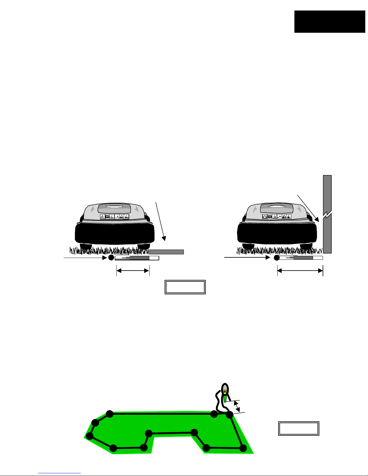
1.1 Using The Roboruler
There are two basic measurements that are used on the Roboruler. The shorter distance is used
along perimeter edges where the area outside the immediate perimeter (about 12 inches/30 cm) is
free of obstacles and is the same relative height as the perimeter edge. The longer distance is used
along perimeter edges where the area outside the immediate perimeter has obstacles or differences
in the height along the perimeter edge. See Figure 1.1.
Perimeter
wire
position
1.2 Starting The Perimeter Wire
Area outside perimeter. Same
basic level and free of obstacles.
Short distance
Figure 1.1
Tear out the perforated center piece on the perimeter wire box. Puncture the plastic covering with
your finger and feel around inside the center of the wire spool for the end of the wire. Pull the wire
end out of the box. The box is designed as a dispenser for the wire so do not remove the wire spool
from the box. After reviewing the illustrations and instructions in the following pages you will be
ready to lay out the perimeter wire and start pegging it to the ground. Figure 1.2
Leave enough wire at the beginning, where the Perimeter Switch is going to be located. Use the
Roboruler to help guide you on placement of the wire along the perimeter. Use a minimum number
of pegs at this point, as you will want to test the wire position at the end of the setup. See Section
2.5 for details on testing the setup.
rea outside perimeter. Has a wall
as an obstacle.
Perimeter
wire
position
>5ft (1.5m)
Long distance
Figure 1.2
Chapter 1
Page 9
Chapter 1
Page 10
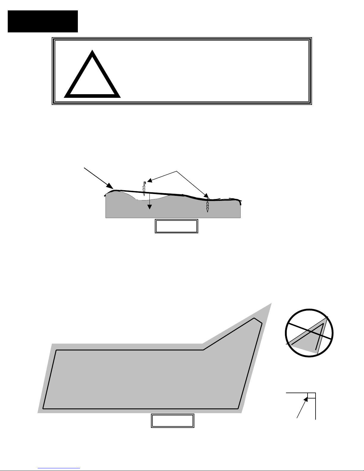
1.3 Fastening The Wire To The Ground
Add pegs in to pull the perimeter wire down to the ground surface, below the grass tips Figure 1.3
WARNING!
!
Perimeter Wire
1.4 Corners & Sharp Turns
Care must be taken not to create a turn sharper than 90 degrees when setting up the perimeter wire.
A turn sharper than 90 degrees can cause the Robomower to lose track of the perimeter wire. In
situations where a corner may require a wire placement of less than a 90-degree angle, placement
can be adjusted using several angles to avoid this. See Figure 1.4.
Lawn area
Damage to the eye is possible. Use proper eye protection
and wear appropriate work gloves when hammering the
pegs. Hard or dry ground may cause pegs to break when
driving them in. In extreme cases, watering the lawn where
the pegs will be driven can be beneficial.
Chapter 1
Page 12
Add pegs in to pull the perimeter wire
down to the ground surface, below the
grass tips.
Figure 1.3
Correct corner
setup using several angles
to avoid a less than 90-
degree angle.
Incorrect corner
setup
Figure 1.4
90 degrees
 Loading...