


Friedrich WY10B33A-B, WS16B30A-C, WS13B30B-C, WS14B10A-C, WY13B33A-B User Manual
...
Service & Parts Manual
WallMaster® Thru-the-Wall |
WS08B10A-C |
|
WS10B10A-C |
|
WS14B10A-C |
|
WS10B30A-C |
72
Power
WS13B30B-C WS16B30A-C WE10B33A-B WE13B33B-B WE16B33A-B WY10B33A-B WY13B33A-B
WM-Svc-Prts-07 (3-07)
|
TABLE OF CONTENTS |
Warranty..................................................................................................................................................... |
3 |
Routine Maintenance ................................................................................................................................ |
4 |
Unit Identification...................................................................................................................................... |
5 |
Performance Data ..................................................................................................................................... |
6 |
Electrical Data ........................................................................................................................................... |
7 |
Functional Component Definitions ......................................................................................................... |
8 |
Electronic Controls ................................................................................................................................... |
9 |
Rotary Controls ....................................................................................................................................... |
10 |
Refrigeration Sequence of Operation ................................................................................................... |
11 |
Sealed Refrigeration Repairs ........................................................................................................... |
12-13 |
Refrigerant Charging .............................................................................................................................. |
13 |
General Troubleshooting.................................................................................................................. |
14-20 |
Wiring Diagrams................................................................................................................................ |
21-25 |
Parts Diagram.......................................................................................................................................... |
26 |
Parts Lists.......................................................................................................................................... |
27-29 |
2

Friedrich Air Conditioning Company
P.O. Box 1540
San Antonio, TX 78295
210.357.4400
www.friedrich.com
WALLMASTER£
THRU-THE-WALL AIR CONDITIONERS
LIMITED WARRANTY
FIRST YEAR
ANY PART: If any part supplied by FRIEDRICH fails because of a defect in workmanship or material within twelve months from date of original purchase, FRIEDRICH will repair the product at no charge, provided room air conditioner is reasonably accessible for service. Any additional labor cost for removing inaccessible units and/or charges for mileage related to travel by a Service Agency that exceeds 25 miles one way will be the responsibility of the owner. This remedy is expressly agreed to be the exclusive remedy within twelve months from the date of the original purchase.
SECOND THROUGH FIFTH YEAR
SEALED REFRIGERANT SYSTEM: If the Sealed Refrigeration System (defined for this purpose as the compressor, condenser coil, evaporator coil, reversing valve, check valve, capillary, filter drier, and all interconnecting tubing) supplied by FRIEDRICH in your Room Air Conditioner fails because of a defect in workmanship or material within sixty months from date of purchase, FRIEDRICH will pay a labor allowance and parts necessary to repair the Sealed Refrigeration System; PROVIDED FRIEDRICH will not pay the cost of diagnosis of the problem, removal, freight charges, and transportation of the air conditioner to and from the Service Agency, and the reinstallation charges associated with repair of the Sealed Refrigeration System. All such cost will be the sole responsibility of the owner. This remedy is expressly agreed to be the exclusive remedy within sixty months from the date of the original purchase.
APPLICABILITY AND LIMITATIONS: This warranty is applicable only to units retained within the Fifty States of the U.S.A., District of Columbia, and Canada. This warranty is not applicable to:
1.Air filters or fuses.
2.Products on which the model and serial numbers have been removed.
3.Products which have defects or damage which results from improper installation, wiring, electrical current characteristics, or maintenance; or caused by accident, misuse or abuse, fire, flood, alterations and/or misapplication of the product and/or units installed in a corrosive atmosphere, default or delay in performance caused by war, government restrictions or restraints, strikes, material shortages beyond the control of FRIEDRICH, or acts of God.
OBTAINING WARRANTY PERFORMANCE: Service will be provided by the FRIEDRICH Authorized Dealer or Service Organization in your area. They are listed in the Yellow Pages. If assistance is required in obtaining warranty performance, write to: Room Air Conditioner Service Manager, Friedrich Air Conditioning Co., P.O. Box 1540, San Antonio, TX 78295-1540.
LIMITATIONS: THIS WARRANTY IS GIVEN IN LIEU OF ALL OTHER WARRANTIES. Anything in the warranty notwithstanding, ANY IMPLIED WARRANTIES OF FITNESS FOR PARTICULAR PURPOSE AND/OR MERCHANTABILITY SHALL BE LIMITED TO THE DURATION OF THIS EXPRESS WARRANTY. MANUFACTURER EXPRESSLY DISCLAIMS AND EXCLUDES ANY LIABILITY FOR CONSEQUENTIAL OR INCIDENTAL DAMAGE FOR BREACH OF ANY EXPRESSED OR IMPLIED WARRANTY.
NOTE: Some states do not allow limitations on how long an implied warranty lasts, or do not allow the limitation or exclusion of consequential or incidental damages, so the foregoing exclusions and limitations may not apply to you.
OTHER: This warranty gives you specific legal rights, and you may also have other rights which vary from state to state.
PROOF OF PURCHASE: Owner must provide proof of purchase in order to receive any warranty related services.
All service calls for explaining the operation of this product will be the sole responsibility of the consumer.
All warranty service must be provided by an Authorized FRIEDRICH Service Agency, unless authorized by FRIEDRICH prior to repairs being made.
(10-04)
3

ROUTINE MAINTENANCE
NOTE: Units are to be inspected and serviced by qualified service personnel only.
Routine maintenance is required annually or semi-annually, depending upon annual usage.
1.Clean the unit air intake filter at least every 250 to 300 fan hours of operation or when the unit’s indicator light is on if so equipped. Clean the filters with a mild detergent in warm water and allow to dry thoroughly before reinstalling.
2.The indoor coil (evaporator coil), the outdoor coil (condenser coil) and base pan should be inspected periodically (yearly or bi-yearly) and cleaned of all debris (lint, dirt, leaves, paper, etc.). Clean the coils and base pan with a soft brush and compressed air or vacuum. If using a pressure washer, be careful not to bend the aluminium fin pack. Use a sweeping up and down motion in the direction of the vertical aluminum fin pack when pressure cleaning coils. Cover all electrical components to protect them from water or spray. Allow the unit to dry thoroughly before reinstalling it in the sleeve.
NOTE: Do not use a caustic coil cleaning agent on coils or base pan. Use a biodegradable cleaning agent and degreaser.
Inspect the indoor blower housing, evaporator blade, condenser fan blade, and condenser shroud periodically (yearly or bi-yearly) and clean of all debris (lint, dirt, mold, fungus, etc.) Clean the blower housing area and blower wheel with an antibacterial / antifungal cleaner. Use a biodegradable cleaning agent and degreaser on condenser fan and condenser shroud. Use warm or cold water when rinsing these items. Allow all items to dry thoroughly before reinstalling them.
3.Periodically (at least yearly or bi-yearly): inspect all control components, both electrical and mechanical, as well as the power supply. Use proper testing instruments (voltmeter, ohmmeter, ammeter, wattmeter, etc.) to perform electrical tests. Use an air conditioning or refrigeration thermometer to check room, outdoor and coil operating temperatures. Use a sling psychrometer to measure wet bulb temperatures indoors and outdoors.
4.Inspect the surrounding area (inside and outside) to ensure that the units’ clearances have not been compromised or altered.
5.Inspect the sleeve and drain system periodically (at least yearly or bi-yearly) and clean of all obstructions and debris. Clean both areas with an antibacterial and antifungal cleaner. Rinse both items thoroughly with water and ensure that the drain outlets are operating correctly. Check the sealant around the sleeve and reseal areas as needed.
6.Clean the front cover when needed. Use a mild detergent. Wash and rinse with warm water. Allow it to dry thoroughly before reinstalling it in the chassis.
4

FRIEDRICH ROOM MODEL NUMBER CODE
W S 08 B 1 0 B
1st DIGIT - FUNCTION
W = Thru-The-Wall, WallMaster Series
2nd DIGIT - TYPE
S = Straight Cool
E = Electric Heat
Y = Heat Pump
3rd & 4th DIGITS - APPROXIMATE BTU/HR (Cooling)
Heating BTU/HR capacity listed in Specifications/Performance Data Section
5th DIGIT - ALPHABETICAL MODIFIER
6th DIGIT - VOLTAGE
1 = 115 Volts
3 = 230-208 Volts
7th DIGIT
0 = Straight Cool & Heat Pump Models ELECTRIC HEAT MODELS
3 = 3 KW Heat Strip, Nominal
8th DIGIT
Major Change
RAC SERIAL NUMBER IDENTIFICATION GUIDE
Serial Number |
|
L |
C |
G |
R |
00001 |
|
Decade Manufactured |
|
|
|
|
|
||
L=0 |
C=3 |
F=6 |
J=9 |
|
|
|
Production Run Number |
A=1 |
D=4 |
G=7 |
|
|
|
|
|
B=2 |
E=5 |
H=8 |
|
|
|
|
|
|
|
|
|
|
|
||
Year Manufactured |
|
|
|
|
Product Line |
||
A=1 |
D=4 |
G=7 |
K=0 |
|
|
|
R = RAC |
B=2 |
E=5 |
H=8 |
|
|
|
|
P = PTAC |
C=3 |
F=6 |
J=9 |
|
|
|
|
E = EAC |
Month Manufactured |
|
|
|
|
V = VPAK |
||
A=Jan |
D=Apr |
G=Jul |
K=Oct |
|
|
|
H = Split |
B=Feb |
E=May |
H=Aug |
L=Nov |
|
|
|
|
C=Mar |
F=Jun |
J=Sept |
M=Dec |
|
|
|
|
|
|
|
|
|
|
|
|
5
6 |
humidity relative 40% & temp air outside F, degree 95 with humidity, relative 50% & .temp air room F, degrees 80 Conditions: Rating * over-Change .satisfactory be will performance heating the unit, the of rating capacity heating resistance the exceed not does loss heat the as long As .heated be to space the of loss heat the Calculate drain optional an desired, is disposal condensate If .35°F approximately of temperature ambient outside preset a at automatic is indicated models on operation resistance to operation pump heat from starts, heat electric the and stops compressor the defrost, During .temperature) coil (outdoor 43°F at terminated and temperature) coil (outdoor 20°F at Initiated CONTROL: DEFROST .available is kit BTU/h, 11000/9100 ratings: following the achieve will unit the mode, heat electric During .mode heat electric in remains unit the 43°F, Below .comfort indoor maintain to fan the with operates then .disposal condensate defrost for pan base outdoor in 50°F approximately at opens automatically Drain DRAIN: DEFROST .watts 3550/2950 and amps, 7.0/14.16 |
|
EVAPORATOR AIR |
EVAPORATOR |
|
|
|
|
|
|
OPERATING |
|
|
|
|
|
|
BREAKER |
|||
|
TEMP. DEG. F |
TEMP. DEG. F |
|
|
|
|
|
|
PRESSURES |
ELECTRICAL RATINGS |
R-22 REF. |
|
|
FUSE |
|||||
|
|
|
|
|
CONDENSER |
|
|
|
|
|
|
|
|
|
|
|
|
|
|
|
Discharge |
Temp. |
|
|
TEMP. |
Discharge |
Suction |
Liquid |
Super |
Sub- |
|
|
Amps |
Amps |
Locked |
Charge in |
Evap |
Motor |
60 Hertz |
|
Air |
Drop F. |
E(in) |
E (out) |
DEG. F |
Temp |
Temp |
Temp |
Heat |
Cooling |
Suction |
Discharge |
Cool |
Heat |
Rotor Amps |
OZ. |
CFM |
RPM |
Amps |
|
|
|
|
|
|
|
|
|
|
|
|
|
|
|
|
|
|
|
|
WS08B10A |
55 |
25 |
55 |
55 |
127 |
165 |
61 |
102 |
18 |
25 |
87 |
281 |
7.1 |
|
36.2 |
20.5 |
257 |
1100 |
15 |
WS10B10A |
52 |
28 |
53 |
51 |
128 |
176 |
68 |
105 |
16 |
24 |
79 |
293 |
9.0 |
|
45.0 |
22.0 |
248 |
1100 |
15 |
WS14B10A |
52 |
28 |
52 |
52 |
128 |
179 |
63 |
99 |
14 |
28 |
82 |
297 |
12.4 |
|
58.0 |
44.9 |
293 |
1300 |
15 |
WS10B30A |
55 |
25 |
53 |
57 |
131 |
179 |
68 |
106 |
16 |
23 |
77 |
289 |
4.6 |
|
26.0 |
22.5 |
235 |
1100 |
15 |
WS13B30B |
51 |
29 |
52 |
50 |
128 |
174 |
57 |
100 |
13 |
30 |
78 |
295 |
6.5 |
|
27.4 |
35.2 |
281 |
1300 |
15 |
WS16B30A |
52 |
28 |
51 |
53 |
121 |
154 |
54 |
99 |
18 |
32 |
74 |
315 |
7.7 |
|
35.0 |
47.6 |
292 |
1421 |
15 |
WE10B33A |
53 |
27 |
54 |
52 |
126 |
180 |
82 |
99 |
16 |
31 |
82 |
289 |
4.6 |
15.2 |
45.0 |
38.0 |
225 |
1074 |
20 |
WE13B33B |
52 |
29 |
52 |
51 |
127 |
180 |
64 |
103 |
13 |
29 |
80 |
295 |
6.5 |
15.7 |
27.4 |
35.0 |
274 |
1318 |
20 |
WE16B33A |
52 |
28 |
51 |
53 |
121 |
174 |
57 |
100 |
18 |
30 |
74 |
315 |
6.5 |
16.1 |
35.0 |
35.2 |
281 |
1305 |
20 |
WY10B33A |
53 |
27 |
54 |
52 |
126 |
180 |
66 |
99 |
16 |
31 |
82 |
225 |
4.6 |
4 / 15.2 |
26.0 |
38.0 |
225 |
1074 |
20 |
WY13B33A |
52 |
29 |
52 |
51 |
127 |
180 |
64 |
103 |
16 |
29 |
80 |
300 |
6.5 |
5.6 / 15.7 |
27.4 |
35.0 |
260 |
1200 |
20 |
|
|
|
|
|
|
|
|
Energy |
|
|
|
|
Cooling |
Heating |
|
|
|
|
|
Efficiency |
Moisture |
Room |
|
|
Capacity |
Capacity |
|
Cooling |
Cooling |
Heating |
Heating |
Ratio |
Removal |
Side Air |
Net Weight |
Model # |
BTU/h |
BTU/h |
Volts Rated |
Amps |
Watts |
Amps |
Watts |
EER |
Pints/Hr. |
Circulation |
Lbs. |
|
|
|
|
|
|
|
|
|
|
|
|
WS08B10A |
8000 |
— |
115 |
6.8 |
762 |
— |
— |
10.5 |
1.3 |
245 |
93 |
WS10B10A |
10000 |
— |
115 |
8.7 |
954 |
— |
— |
10.5 |
2.4 |
245 |
103 |
WS14B10A |
13500 |
— |
115 |
12.0 |
1415 |
— |
— |
9.5 |
3.3 |
295 |
112 |
WS10B30A |
10000/10000 |
— |
230/208 |
4.6/5.0 |
1005/996 |
— |
— |
10.0/10.0 |
2.1 |
260 |
101 |
WS13B30B |
12500/12000 |
— |
230/208 |
6.3/6.7 |
1404/1379 |
— |
— |
8.9/8.7 |
3.3 |
280 |
109 |
WS16B30A |
15800/15000 |
— |
230/208 |
7.8/8.5 |
1756/1705 |
— |
— |
9.0/8.8 |
4.2 |
290 |
119 |
WE10B33A |
10000/10000 |
11000/9100 |
230/208 |
4.6/5.0 |
1005/996 |
16.0/14.7 |
3550/2950 |
10.0/10.0 |
2.1 |
260 |
103 |
WE13B33B |
12500/12000 |
11000/9100 |
230/208 |
6.3/6.7 |
1404/1379 |
16.0/14.7 |
3550/2950 |
8.9/8.7 |
3.3 |
280 |
111 |
WE16B33A |
15800/15000 |
11000/9100 |
230/208 |
7.8/8.5 |
1756/1705 |
16.0/14.7 |
3550/2950 |
9.0/8.8 |
4.2 |
290 |
121 |
WY10B33A |
10100/9800 |
8100/7800 |
230/208 |
4.6/4.8 |
1013/976 |
3.9/4.0 |
857/821 |
10.0/10.0 |
2.5 |
230 |
107 |
WY13B33A |
12500/12100 |
10400/10000 |
230/208 |
6.4/6.8 |
1389/1352 |
5.4/5.7 |
1182/1136 |
9.0/9.0 |
3.2 |
280 |
116 |
Installation Information
|
Circuit Rating |
Plug Face |
Wall |
||||||||
|
Breaker |
Outlet |
|||||||||
Model Numbers |
or T-D Fuse |
(NEMA#) |
Appearance |
||||||||
|
|
|
|
|
|
|
|
|
|
|
|
WS08B10A, WS10B10A, |
125V - 15A |
5 - 15P |
|
|
|
|
|
|
|
|
|
WS14B10A |
|
|
|
|
|
|
|
|
|
||
|
|
|
|
|
|
|
|
|
|
|
|
|
|
|
|
|
|
|
|
|
|
|
|
WS10B30A, WS13B30A, |
250V - 15A |
6 - 15P |
|
|
|
|
|
|
|
|
|
WS16B30A |
|
|
|
|
|
|
|
|
|
||
|
|
|
|
|
|
|
|
|
|
|
|
|
|
|
|
|
|
|
|
|
|
|
|
WE10, WE13, WE16 |
250V - 20A |
6 - 20P |
|
|
|
|
|
|
|
|
|
WY10, WY13 |
|
|
|
|
|
|
|
|
|
||
|
|
|
|
|
|
|
|
|
|
|
|
|
|
|
|
|
|
|
|
|
|
|
|
Sleeve Dimensions
|
|
|
|
Depth |
Minimum |
Minimum |
Thru-the-wall |
|
|
|
|
|
with |
Extension |
Extension |
Finished Hole |
|
Model |
Height |
Width |
Depth |
Front |
Into Room |
Outside |
Height |
Width |
|
|
|
|
|
|
|
|
|
WSC Sleeve |
16 3/4" |
27" |
16 3/4" |
23" |
7 1/2" |
9/16" |
17 1/4" |
27 1/4" |
Chassis |
15 3/4" |
26 1/2" |
21" |
– |
– |
– |
– |
– |
DATA PERFORMANCE
ELECTRICAL DATA
Wire Size |
Use ONLY wiring size recommended for |
|
single outlet branch circuit. |
Fuse/Circuit |
Use ONLY type and size fuse or HACR |
Breaker |
circuit breaker indicated on unit’s rating |
|
plate. Proper current protection to the unit |
|
is the responsibility of the owner. |
Grounding |
Unit MUST be grounded from branch |
|
circuit through service cord to unit, or |
|
through separate ground wire provided on |
|
permanently connected units. Be sure that |
|
branch circuit or general purpose outlet is |
|
grounded. |
Receptacle |
The field supplied outlet must match plug on |
|
service cord and be within reach of service |
|
cord. Do NOT alter the service cord or plug. |
|
Do NOT use an extension cord. Refer to |
|
the table above for proper receptacle and |
|
fuse type. |
ELECTRIC SHOCK HAZARD.
Turn off electric power before service or installation.
All electrical connections and wiring MUST be installed by a qualified electrician and conform to the National Electrical Code and all local codes which have jurisdiction.
Failure to do so can result in property damage, personal injury and/or death.
The consumer - through the AHAM Room Air Conditioner Certification Program - can be certain that the AHAM Certification Seal accurately states the unit’s cooling and heating capacity rating, the amperes and the energy efficiency ratio.
7
FUNCTIONAL COMPONENTS
A. Mechanical components
Bellows condensate valve
Temperature-sensitive valve that opens up to drain off condensate water when the outside temperature falls below 40°F and closes when the outside temperature reaches 58°F.
Plenum assembly
Diffuser with directional louvers used to direct the conditioned airflow.
Blower wheel
Attaches to the indoor side of the fan motor shaft and is used for distributing unconditioned, room side air though the heat exchanger and delivering conditioned air into the room.
Slinger fan blade
Attaches to the outdoor side of the fan motor shaft and is used to move outside air through the condenser coil, while slinging condensate water out of the base pan and onto the condenser coil, thus lowering the temperature and pressures within the coil.
B. Electrical components
Thermostat
Used to maintain the specified room side comfort level
System switch
Used to regulate the operation of the fan motor, the compressor or to turn the unit off. For troubleshooting, refer to the wiring diagrams and schematics in the back of this service manual.
Capacitor
Reduces line current and steadies the voltage supply, while greatly improving the torque characteristics of the fan motor and compressor motor.
MoneySaver® switch
When engaged, it sends the power supply to the fan motor through the thermostat, which allows for a cycle-fan operation.
Fan Motor
Dual-shafted fan motor operates the indoor blower wheel and the condenser fan blade simultaneously.
Solenoid
Used to energize the reversing valve on all heat pump units.
Heating element
Electric resistance heater, available in 3.3, 4.0 or 5.2 kW on select TwinTemp® models.
Heat anticipator
Used to provide better thermostat and room air temperature control.
C. Hermetic components
Compressor
Motorized device used to compress refrigerant through the sealed system.
Reversing valve
A four-way switching device used on all heat pump models to change the flow of refrigerant to permit heating or cooling.
Check valve
A pressure-operated device used to direct the flow of refrigerant to the proper capillary tube, during either the heating or cooling cycle.
Capillary tube
A cylindrical meter device used to evenly distribute the flow of refrigerant to the heat exchangers (coils.)
8
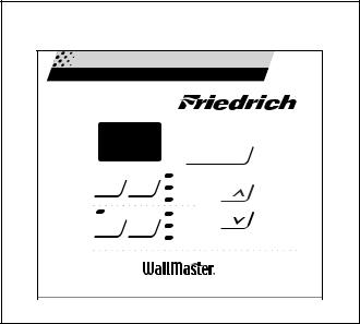
SYSTEM CONTROL PANEL
(“WS” Models)
Figure 6: System Control Panel |
|||
72 |
|
|
|
|
|
Cool |
|
Fan |
Mode |
Money Saver® |
|
Speed |
|
|
|
|
|
Fan Only |
|
|
|
Clock |
|
Timer |
Set |
Start Time |
|
On/Off |
Hour |
Stop Time |
|
|
|
Temp/Hour |
|
TESTING THE ELECTRONIC CONTROL
CHECKING ROOM TEMPERATURE
1.Check the room temperature at the electronic control pad by pressing at the same time the “FAN SPEED” button and the temperature “UP” button on XQ & WS models.
2.The indoor temperature will display for 10 seconds. Indoor temperature can be viewed in all modes, including the TEST mode. The display can be changed back to SET temperature by pressing any key, except the ON/OFF button, or after 10seconds has elapsed.
ACTIVATING TEST MODE
Activate test mode by pressing at the same time the “MODE” button and the temperature “DOWN” button on XQ & WS models. LEDs for Hour, Start, and Stop will blink 1bps while Test Mode is active.
Test Mode has duration of 90 minutes. Test Mode can be activated under any conditions, including Off. Test Mode is cancelled by pressing the On/Off button, unplugging the unit, or when the 90 minutes is timed out. All settings revert to the factory default settings of Cool, 75 degrees F, Timer and Set Hour features are nonfunctional.
Test Mode overrides the three-minute lockout, all delays for compressor and fan motor start / speed change, and no delay when switching modes.
Test Mode default settings are ON, Money Saver, 60 degrees F, and High fan speed.
Activating Error Code Mode (Submode of Test Mode) Unit must be in Test Mode to enter Error Code Mode
1.Activate Error Code Mode by pressing the “TIMER ON/OFF” button on XQ & WS models. LED for the “TIMER ON/OFF” will flash 1bps while Error Code Mode is active. Pressing the “TEMP/HR + ” button will display 00. Consecutive presses will scroll through all error codes logged. Press the “TEMP/HR - ” button to see the reverse order of all error codes logged. When the end of logged error codes is reached the temperature set point will appear.
IMPORTANT
Error Codes are cleared from the log by exiting from Error Code Mode. To exit on XQ & WS models, press Timer On/ Off button. Or unplug unit to exit Error Code Mode. Plug unit in after 5 seconds to resume normal operation of unit.
ERROR CODE LISTINGS
E1 SHORT CYCLE SITUATION: Defined as compressor powered on before the three minute time delay ten times in one hour. Investigate and correct short cycling problem.
E2 KEYBOARD STUCK ERROR: If key button(s) are pressed continuously for twenty seconds or more. If MODE key is stuck, unit will default to cool. Exit Error Code Mode to see if error “E2” is no longer displayed and unit is functioning. Replace board if “E2” still displays after exiting Error Code Mode.
E3 FROST PROBE OPEN: Normal operation is allowed. Ohm frost probe. Replace probe if ohm value not read. If ohm value present replace board.
E4 FROST PROBE SHORT: Normal operation allowed. Replace probe.
E5 INDOOR PROBE OPEN: Control assumes indoor ambient temperature is 90 degree F and unit will operate. Ohm indoor probe. Replace probe if ohm value not read.
E6 INDOOR PROBE SHORT: Control assumes ambient temperature is 90 degree F and unit will operate. Replace probe.
NOTE: All Error Code displays for Frost & Indoor Probe will allow unit to operate. Unit may or will ice up if faulty components not replaced.
9
 Loading...