

Page 1
Window Installation Instructions
Room Air Conditioners
115-Volt:
KWIKQA - Q Chassi
s Models
SQ06, SQ08
115-Volt: EQ08
AUTO
F
C
AUTO FAN
AM
CONTINUOUS
PM
88
ONOFF
SET POINT
SCHEDULE
ROOM TEMP
CHECK $MART
AUTO SPEED
FILTER
SYSTEM
FAN MODE
POWER
FAN SPEED
SCHEDULE
93001013_00
Page 2
Installation Instructions
READ THIS FIRST! Electrical Requirements
NOTE: This section includes installation instructions for window mount
and thru-the-wall mount methods. Kühl heat/cool units are
designed for permanent thru-the-wall installation. Mounting the
unit in a window will require a window accessory kit, available
through your Friedrich dealer.
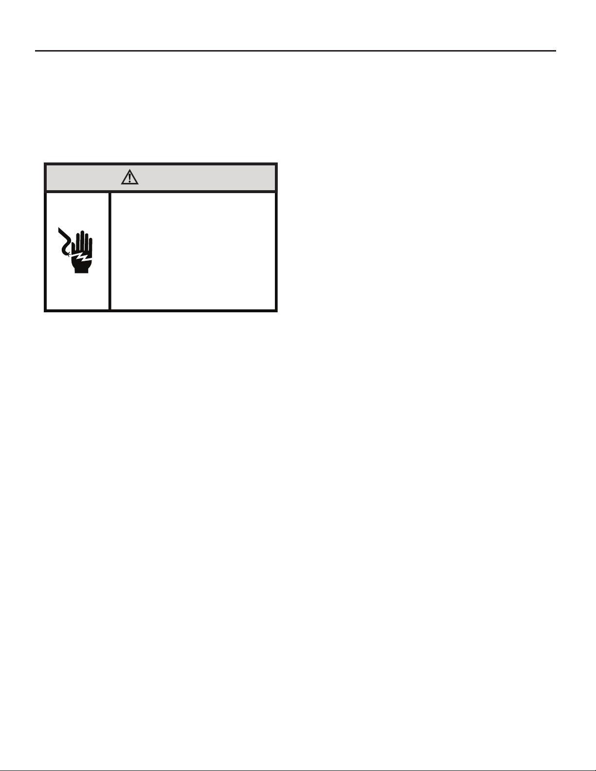
WARNING
Electrical Shock Hazard
Make sure your electrical receptacle has the
same configuration as your air conditioner’s
plug. If different, consult a Licensed Electrician.
Do not use plug adapters.
Do not use an extension cord.
Do not remove ground prong.
Unplug unit prior to performing any service.
Always plug into a grounded 3 prong oulet.
Failure to follow these instructions can result in
death, fire, or electrical shock.
IMPORTANT: Before you begin the actual installation of the air conditioner,
be sure your electrical requirements are as described below. Consult an
electrical professional as necessary to insure home wiring is per local
electrical codes.
CIRCUIT PROTECTION – An overloaded circuit will invariably cause
malfunction or failure of an air conditioner, therefore, it is necessar y that the
electrical protection is adequate. Due to momentary high current demand
when your air conditioner is started, use a "TIME DELAY" fuse or a HACR
type circuit breaker. Consult your dealer or power company if in doubt.
Your air conditioner must be connected to a power supply with the same
A.C. voltage and hertz as marked on the unit nameplate. Only alternating
current (A.C.), no direct current (D.C.), can be used.
The power cord has a plug with a grounding prong of approved type and a
matching plug receptacle with ground is required. Refer to page 5 for the
correct type of plug receptacle for your model.
2
Page 3
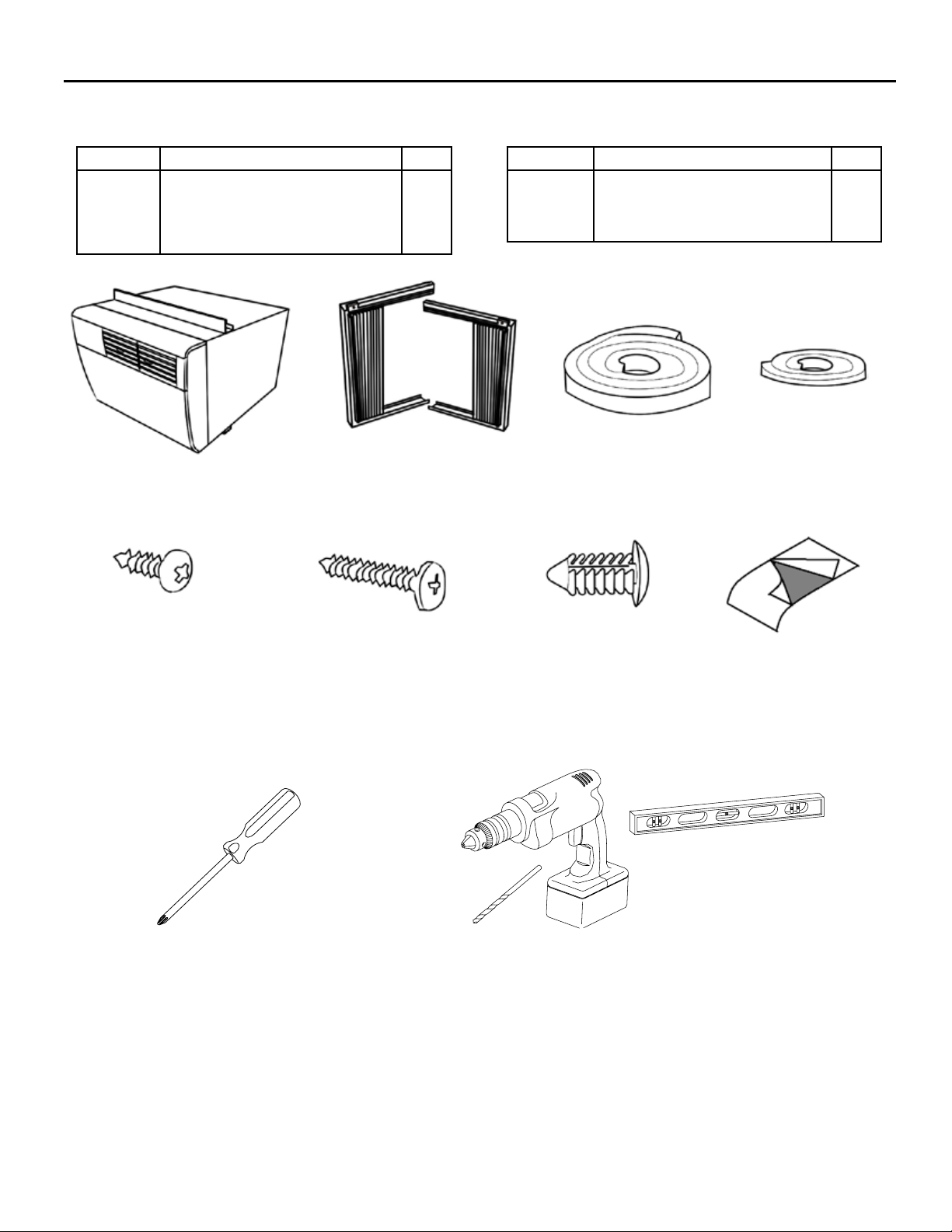
Items required for installation (included in cooling only units, sold separately for heat/cool models)
ITEM NO DESCRIPTION QT Y.
A
B
C
D
Q KÜHL UNIT
Q SIDE CURTAINS (INCLUDES 8 PUSH PINS)
WINDOW SEAL GASKET
SHELL GASKET (ADHESIVE-BACK)
for replacement installations only
A
1
2
1
1
B
ITEM NO DESCRIPTION QT Y.
E
F
G
H
SCREW #8 x ½" (BLUE BAG)
SCREW #8 x 1 ¼" (GREY BAG)
SPARE PUSH PINS
R1 INSULATION PANEL
C
6
5
4
1
D
E F G
Recommended tools required for installation: (not included)
Required for all installations
PHILLIPS SCREWDRIVER
NOTE: Protective clothing and gear should be worn & used while installing the unit (ex: protective eyewear, gloves, boots, etc…)
FOR WINDOW INSTALLATIONS, PROCEED TO THE NEXT PAGE.
Recommended for thru-the-wall installations
LEVEL
POWER DRILL & ⅛” DRILL BIT
H
FOR THRU-THE-WALL INSTALLATIONS, SKIP TO PAGE 22.
15
Page 4
Standard Window Installation
IMPORTANT: Some municipalities or jurisdictions require that window
units are installed by licensed contractors. Check your local codes and
ordinances prior to attempting installation.
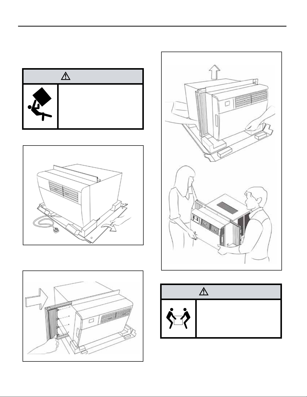
WARNING
Falling Object Hazard
Not following Installation Instructions
for mounting your air conditioner can
result in property damage, injury, or
death.
STEP 1. Fold down the sides of the carton bottom tray. (See Figure 12).
Figure 12
STEP 3. Once both curtains have been installed, slide hands
underneath the unit to lift and carry to the window, as shown
in Figure 14 below. Obtain assistance as needed
Figure 14
STEP 2. Install side curtains (B in parts list) on both sides of the unit.
Press in the attached push pins (4 on each side) to secure
curtains to the sleeve. (See Figure 13)
Figure 13
16
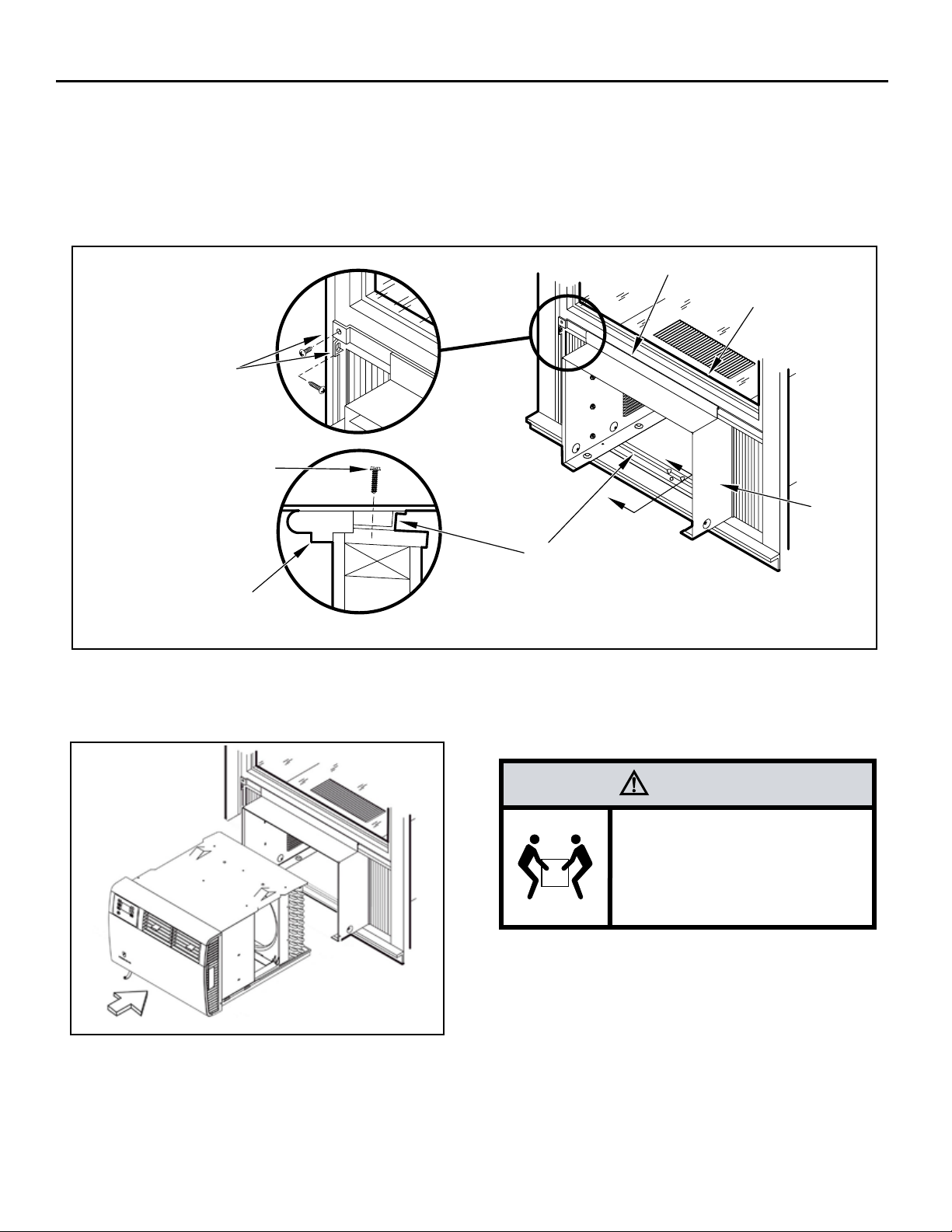
CAUTION
Excessive Weight Hazard
Use two or more people when
installing your air conditioner.
Failure to do so can result in
back or other injury.
Page 5

STEP 4. Place unit in window with the bottom support rail up against the
back edge of the window sill. Center and close window sash
onto upper support rail. The unit should be slightly tilt
ed
outside (1/4" tilt). (See Figure 15) NOTE:
Depending on the type of window, install the appropriate
security lock as recommended by manufacturer.
Figure 15
If you desire a more permanent installation, you can secure your
curtains using both screw holes and your unit sleeve directly to
the lower window stool using the instruction Steps 5.1 - 5.3 shown
below. If you choose the standard installation already covered in
Steps 1 - 5, then you can proceed to Step 6 found on Page 18.
STEP 5.1.
Pull unit from sleeve, using the side handles located on
either side of the decorative front. Obtain assistance as
needed. Place unit out of the way on a secure, at surface.
(See Figure 17)
Figure 17
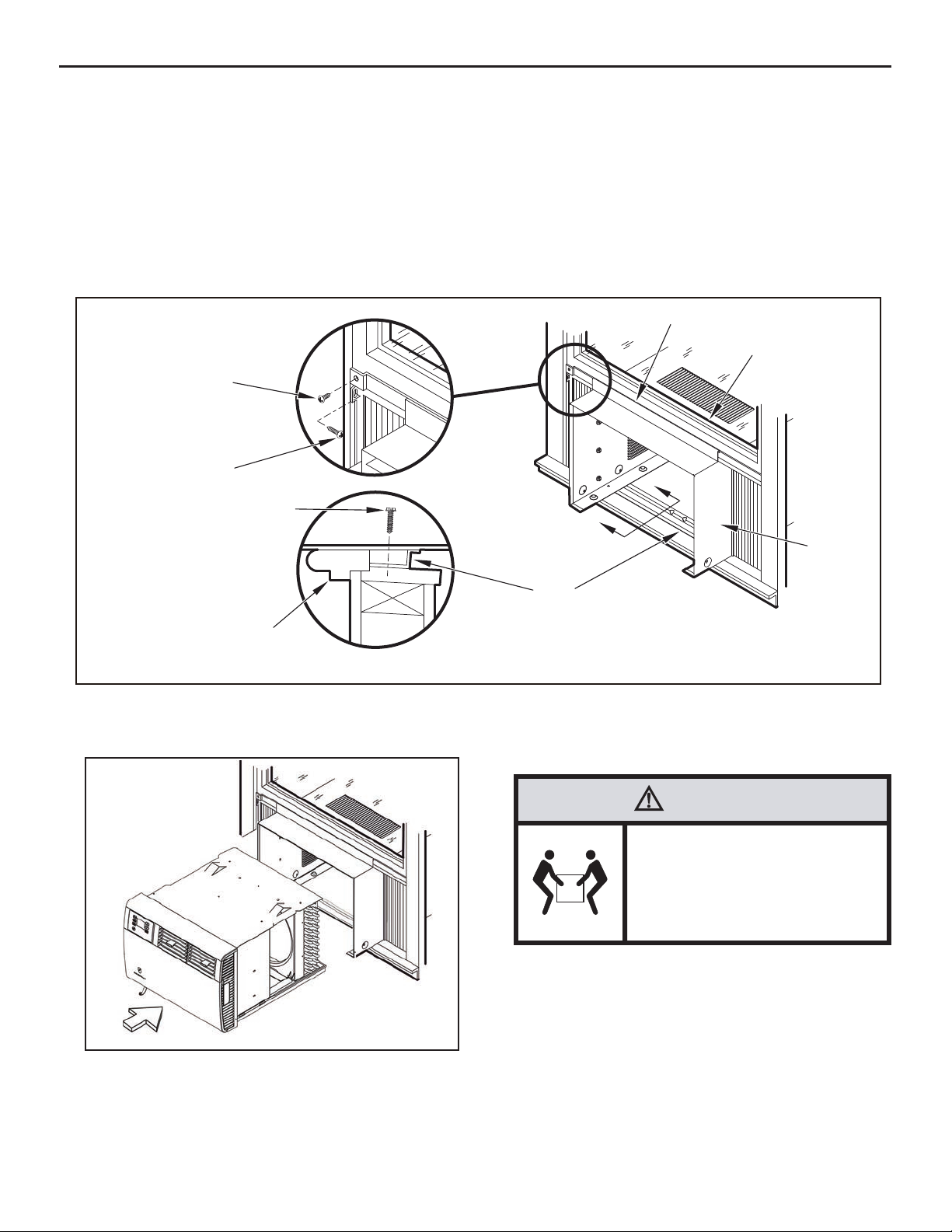
STEP 5. Extend side curtains to ll window. Secure outer top corner
of both curtain (left and right) to window jamb and window
sash using supplied screws. 1/2" screws (Item E in parts list)
and 1 1/4" screws ( Item F: in parts list) have been provided to
accommodate varying window types. (See Figure 16)
Figure 16
SECURE TO WINDOW
SASH THROUGH TOP
SCREW HOLE
SECURE TO
WINDOW JAMB
THROUGH
BOTTOM / SIDE
SCREW HOLE
THIS STEP MUST BE FOLLOWED COMPLETELY TO INSURE
UNIT IS ADEQUATELY SECURED TO WINDOW.
NOTE: WHEN REMOVING UNIT FROM SLEEVE AND CARRYING OR
HANDLING UNIT, OBTAIN ASSISTANCE OR HELP AS NECESSARY
TO SUPPORT UNIT FROM BOTTOM (BASEPAN), MAINTAINING
CLEARANCE FROM ALL OBSTACLES. (See image below)
CAUTION
Cut/Sever
Although great care has been
taken to minimize sharp edges
in the construction of your unit,
use gloves or other hand
protection when handling unit
Failure to do so can result in minor
to moderate personal injury.
17
Page 6
STEP 5.2.
Once unit is removed from sleeve, secure sleeve to window sill through screw hole in the bottom center of sill channel using 1 supplied 1 ¼" screw (F in parts list) . (See Figure 18 A-A)
In Step 5, the window curtains were secured using 1 supplied screw per curtain (2 screws total). For a more permanent application,
you may secure each curtain with an additional screw through the remaining screw hole, insuring each window curtain is secured
to window jamb and sash with 2 screws each (4 screws total). Two sizes of screws (E and F in parts list) have been provided to
accommodate varying window types. (See Figure 18)
NOTE: Securing the curtains using both screw hole locations may not work in certain window types. For those applications, use only
1 screw per curtain and install the appropriate security lock as recommended by window manufacturer.
Figure 18
SECURE CURTAINS
THROUGH REMAINING
HOLES USING EITHER 1/2"
SCREWS (ITEM E: BLUE
BAG) OR 1 1/4" SCREWS
(ITEM F: GREY BAG).
SECURE SILL CHANNEL
TO WINDOW STOOL
USING (1) 1 1/4" SCREW
(ITEM F: GREY BAG).
WINDOW STOOL
STEP 5.3.
Figure 19
Inspect unit prior to inserting back into sleeve. Manually rotate fan to see that it turns freely. Make sure electrical cord is positioned
in the front of unit and out of the way when inserting it back into the sleeve.
Insert unit back into sleeve by positioning onto bottom rails of sleeve and pushing back into place. Obtain assistance as needed.
(See Figure 19)
SECTION A-A
SILL
CHANNEL
SHELL SUPPORT CHANNEL
WINDOW SASH
A
A
SLEEVE
18
CAUTION
Excessive Weight Hazard
Use two or more people when
installing your air conditioner.
Failure to do so can result in
back or other injury.
NOTE: WHEN CARRYING OR HANDLING UNIT, OBTAIN ASSISTANCE
OR HELP AS NECESSARY TO SUPPORT UNIT FROM BOTTOM
(BASEPAN), MAINTAINING CLEARANCE FROM ALL OBSTACLES.
Page 7
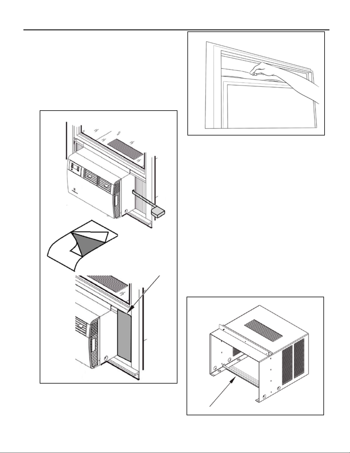
STEP 6. To minimize air leaks and ensure optimal insulation, install
the included R1 insulation panel. (H in parts list) (See Figure
20 A-C).
Firs
t, measure the width from one side of the air condi-
tioner to the end of the side curtain. (See Figure 20A)
Next cut the R1 insulation panel to the measured width
and remove protective cover, exposing adhesive on
back panel (See Figure 20B)
Last, evenly apply the adhesive side of the panel to the top
and botom of the side curtain frame. (See Figure 20C)
Repeat the step above for the other side curtain frame.
Figure 20
Figure 21
STEP 8.
Now that installation is complete, your unit is ready to operate!
A
Simply plug in the power cord and follow the operation steps
outlined in this manual or your QuickStart Guide.
CIRCUIT PROTECTION - If the air conditioner is circuit protected by a fuse,
use a "TIME DELAY" fuse or HACR type circuit breaker due to momentary
high current demand when your air conditioner is started. Before operating
your unit, verify the ampere rating of the time-delay fuse or circuit breaker
which protects your unit. The ampere rating of the time-delay fuse or circuit
breaker shall be 15 amps
Plug in unit..
Replacement Installation Instructions
B
C
Your new Kühl Q chassis will t in all previous Friedrich Q-size
sleeves. Replacement installation instructions are the same for
both window and thru-the-wall.
Inspect your existing Friedrich Q-size sleeve to ensure it is
properly installed and in good condition.
Remove adhesive backing from supplied shell gasket (D in parts list) and
place along the bottom sill channel, centered, extending up the sides of
the shell. (see Figure 22).
Remove the new Kühl Q chassis from the new sleeve (as outlines
in STEP 5.1 on page 17).and insert into previously installed sleeve.
Obtain assistance as needed.
Figure 22
STEP 7.
Cut the window seal gasket (C in parts list) to match the
window width and insert it between the window sashes
as shown in Figure 21.
SHELL GASKET (ITEM D).
19
Page 8
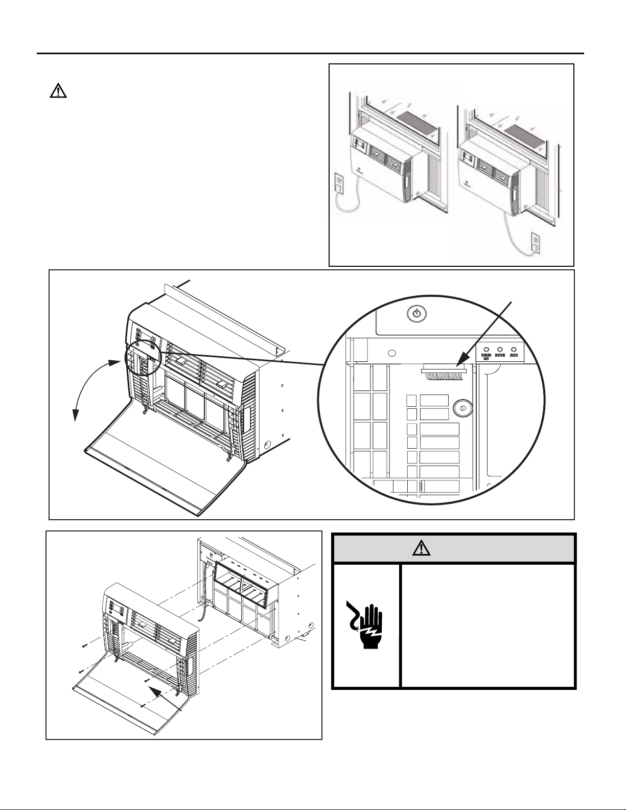
Cord Routing Change
Unplug unit.
Your Kühl Q unit will come with the power cord already installed and routed
to the left side of the unit.
For convenience and optimum appearance the direction of the power
cord can be changed from left to right by following the procedure below.
Select the exit location on the left or right based on proximity to the power
outlet. (See Figure 23)
STEP 1. Remove the decorative front cover. (See A thru D and Figures
24A and 24B below)
A. Open the decorative front cover.
B. Locate and disconnect electronic control power cable harness.
C. Remove 4 screws attaching decorative front cover.
Save to reinstall later..
D. Remove decorative front cover. Store in a safe place to
reinstall later. (no image).
Figure 24A
Figure 23
B.
A.
Figure 24B
WARNING
Electrical Shock Hazard
Make sure your electrical receptacle has the
same configuration as your air conditioner’s
plug. If different, consult a Licensed Electrician.
Do not use plug adapters.
Do not use an extension cord.
Do not remove ground prong.
Unplug unit prior to performing any service.
Always plug into a grounded 3 prong oulet.
Failure to follow these instructions can result in
death, fire, or electrical shock.
20
C.
Page 9
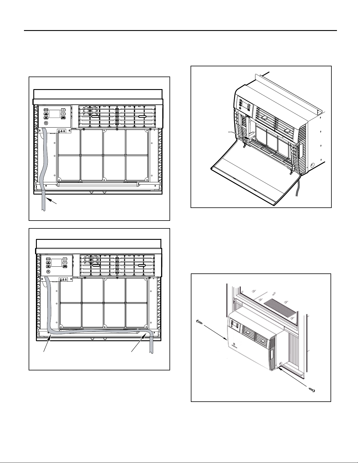
FRR099
STEP 2. Route the cord along bottom inside of the unit (See Figures 25
and 26), under the lower left mounting screw embossments
and exit the cord through right side cord opening (See Figure
26) of the decorative front cover. Decorative front cover will
keep cord in place.
Figure 25
FACTORY SETTING WITH LEFT-SIDE
CORD PLACEMENT
FRR201
STEP 3. Reinstall the 4 screws removed earlier to secure decorative
front cover with cord exiting to the front bottom of the unit. (4
screws RETAINED FROM STEP 1) and re-connect the power
cable harness (disconnected in STEP 1).
Figure 27
CLOSE-UP OF
CORD UNDER
LEFT MOUNTING
SCREW
EMBOSSMENT
Figure 26
NEW CORD ALIGNMENT FOR ROUTING CORD
EXIT TO THE RIGHT OF UNIT
EntryGuard Security Lock
For additional safety, your unit is equipped with EntryGard™ protection,
a feature that helps prevents kick-in intrusions. To engage this feature,
use 2 supplied 1/2" screw (E in parts list) to secure decorative front
cover to sleeve. (See Figure 28 for screw hole locations) .
Figure 28
FRR202
21
Page 10

Friedrich Air Conditioning Co.
10001 Reunion Place, Suite 500 • San Antonio, Texas 78216
1-800-541-6645
www.friedrich.com
Printed in the U.S.A.
93001013_00
Page 11

Unidades de Aire Acondicionado
AUTO
F
C
AUTO FAN
AM
CONTINUOUS
PM
88
ONOFF
SET POINT
SCHEDULE
ROOM TEMP
CHECK $MART
AUTO SPEED
FILTER
SYSTEM
FAN MODE
POWER
FAN SPEED
SCHEDULE
Manual de Instalación de Ventana
KWIKQA - Q Chassis Models
Kühl
Kühl +
Frío & Calor Eléctrico
93001013_00
115-Voltios: SQ06, SQ08
115-Voltios: EQ08
Page 12

Instrucciones de Instalación
NOTA: Esta sección incluye instrucciones de instalación para el montaje en
ventanas y métodos de montaje a través de la pared. Las
unidades Kaül de calor / frío están diseñadas para una instalación
permanente a través de la pared. Montar la unidad en una ventana
requerirá un conjunto de accesorios de ventana, disponible a
través de su distribuidor Friedrich.
ADVERTENCIA
Peligro de Descarga Eléctrica
Asegurarse de que su enchufe eléctrico tenga la
configuración que el enchufe de su aire
misma
acondicionado. Si es diferente, consultar a un
electricista certificado.
No utilizar adaptadores de enchufe.
No utilizar un cable de extensión.
No quitar la clavija de tierra.
Conectar siempre a una toma de corriente de 3 clavijas
con conexión a tierra.
El incumplimiento de estas instrucciones puede
ocasionar la muerte, un incendio o una descarga
eléctrica.
¡
LEA ESTO PRIMERO! Requerimientos Eléctricos
IMPORTANTE: Antes de comenzar la instalación misma del aire
acondicionado, asegúrese de que sus requerimientos eléctricos sean como
se describen a continuación. Consulte a un electricista profesional si es
necesario para asegurarse que el cableado de la vivienda está de acuerdo
a los códigos eléctricos locales.
PROTECCIÓN DE CIRCUITO – Un circuito sobrecargado invariablemente
provocará un mal funcionamiento o la descompostura de un aire
acondicionado, por lo tanto, es
adecuada. Debido al alto requerimiento momentáneo de corriente cuando
se inicia el aire acondicionado, utilice un fusible de "RETARDO" o un
interruptor automático del circuito de tipo HACR. Consulte a su distribuidor
o la compañía de energía en caso de duda.
Su aire acondicionado debe estar conectado a una fuente de alimentación
con el mismo voltaje de corriente alterna y Hertz como está indicado en la
identificación de la unidad. Sólo se puede utilizar corriente alterna
placa de
(A.C., en inglés), no corriente directa (D.C., en inglés).
El cable de alimentación tiene un enchufe con una clavija de tierra del tipo
aprobado y se requiere de una toma de corriente que coincida con el
enchufe con conexión a tierra. Vea la página 6 para el tipo correcto de
conexión de la toma de corriente para su modelo.
necesario que la protección eléctrica sea la
12
Page 13

Artículos necesarios para la instalación (incluidos únicamente en las
No ARTÍCULO
unidades de enfriamiento directo)
DESCRIPCIÓN CANT.
A
B
C
D
-UNIDAD KÜHL "Q"
-CORTINAS LATERALES Q
( INCLUYE 8 pines de empuje )
-CINTA SELLADORA
-CINTA SELLADORA - ADHESIVO -ATRAS
Sólo para instalaciones de reemplazo
1
2
1
1
N
o ARTÍCULO
E
F
G
H
DESCRIPCIÓN CANT.
TORNILLO # 8 x ½ " ( BOLSA AZUL)
TORNILLO # 8 x 1 ¼ " ( BOLSA GRIS)
TACHUELAS DE REPUESTO
PANEL DE AISLAMIENTO R1
6
5
4
1
D
C
A
B
E F G
H
Herramientas recomendadas para la instalación : (no incluido )
Necesario para todas las instalaciones
DESTORNILLADOR PHILLIPS
NOTA : Ropa de protección y equipo se deben usar durante la instalación de la unidad (por ejemplo: gafas de protección, guantes, botas, etc)
Recomendado para instalaciones de pared
NIVE LAD O R
TALADRO, ⅛ " BROCA
PARA INSTALACIONES DE VENTANAS , PROCEDA A LA PÁGINA SIGUIENTE .
PARA INSTALACIONES DE VENTATA, VAYA A LA PG 22 .
45
Page 14

Instalación de Ventana Estándar
IMPORTANTE : Algunos municipios o jurisdicciones requieren que las
unidades de ventana son instalados por contratistas con licencia .
Consulte los códigos y ordenanzas locales antes de intentar la
instalación .
ADVERTENCIA
Peligro por la Caída de Objetos
El no seguir las instrucciones de instalación
para el montaje de su aire acondicionado
puede resultar en daños a los bienes, en
lesiones o en la muerte.
PASO 1. Dobla hacia abajo de los lados de la bandeja
inferior del cartón . ( Ver Figura 12 )
Figure 12
PASO 3. Una vez que se han instalado dos cortinas , deslice las
m
anos debajo de la unidad para levantar y transportar a la
ventana , como se muestra en la Figura 14. Obtener asistencia
según sea necesario
Figure 14
PASO 2. Instale las cortinas laterales (B en la lista de piezas ) en
ambos lados de la unidad . Pulse en los pasadores de empuje
adjuntos ( 4 en cada lado ) para asegurar cortinas a la cubierta .
( Ver Figura 13 )
Figure 13
46
PRECAUCIÓN
Peligro de Peso Excesivo
Recurrir a dos o más personas durante la instalación
del aire acondicionado. De no hacerlo puede resultar
con lesiones en la espalda o de otro tipo.
Page 15

Paso 5
Coloque la unidad en la ventana con el carril de soporte
inferior contra el borde posterior de la r
ventana. Centre y cierre el alféizar de ventana sobre el
riel de soporte superior . La unidad debe estar al mismo
nivel o ligeramente inclinada hacia fuera . ( Ver Figura
15 ) NOTA : Dependiendo del tipo de ventana , instale el
bloqueo de seguridad apropiada según lo recomendado
por el fabricante .
episa de la
Figure 15
PASO 5. Extender cortinas laterales para llenar la ventana .
Asegure la esquina superior externa de ambos cortinas (izquierda
y derecha) a la jamba y marco de la ventana con los tornillos
suministrados . 1/2 " tornillos ( artículo E en la lista de piezas ) y 1
1/4 " tornillos ( Punto F : en la lista de piezas ) se han previsto para
dar cabida a diferentes tipos de ventanas . ( Véase la Figura 16 )
Figure 16
Si usted desea una instalación más permanente , puede asegurar
las cortinas con los dos tornillos y la manga directamente en la
repisa de la ventana inferior siguiendo los pasos 5.1 - 5.3 que se
muestran a continuación. Si eligio la instalación estándar ya
cubiertos en los pasos 1 - 5 , entonces se puede proceder al Paso 6
que encuentra en la página 25 .
STEP 5.1.
Figu
CUANDO CARGE O MANIPULE LA UNIDAD, SOLICITE ASISTENCIA
O AYUDA SI ES NECESARIO PARA SOSTENER LA UNIDAD DE LA
PARTE INFERIOR (BANDEJA BASE), MANTENIÉNDOSE ALEJADO
DE TODOS LOS OBSTÁCULOS.
Saque La Unidad de la funda usando el lado manijas
localizadas a cada lado de la parte frontal decorativo.
Obtener asistencia según sea necesario. Coloque la
unidad fuera del camino en una superficie plana y
segura . ( Ver Figura 17 )
re 17
Asegure al del marco
de la ventana a traves
del orificio del
tornillo que esta encima
Asegure a la
jamba de la
ventana por la
parte inferior / a
lado agujero del
tornillo
ESTE PASO DEBE SEGUIR POR COMPLETO PARA
ASEGURAR UNIDAD ESTE ADECUADAMENTE FIJADA EN LA
VENTANA.
PRECAUCIÓN
Cortar / Rebanar
Aunque se ha tenido mucho cuidado para reducir al
mínimo los bordes afilados en la fabricación de la
unidad, utilizar guantes u otro tipo de protección para
el manejo de la unidad.
De no hacerlo puede resultar con lesiones
personales de menores a
moderadas.
47
Page 16
STEP 5.2.
\ central de canal alféizar usando 1 suministra 1 ¼ " tornillo (F en la lista de piezas ) . ( Véa la Figura 18 A- A)
Una vez que la unidad se quita de la manga , manga seguro a alféizar de la ventana a través del agujero del tornillo en la parte inferior
En el paso 5 , las cortinas de la ventana se fijan con 1 tornillo por cortina ( 2 tornillos en total). Para una aplicación más permanente ,
puede asegurar cada cortina con un tornillo adicional a través del orificio del tornillo restante , asegurando cada cortina de la ventana
está fijado a jamba de la ventana y la banda con 2 tornillos cada uno (4 tornillos en total). Dos tamaños de tornillos ( E y F en la lista
de piezas ) se han previsto para dar cabida a diferentes tipos de ventanas . ( Ver Figura 18 )
NOTA : Asegurar las cortinas con las dos tornillos de los orificios de los tornillos puede no funcionar en ciertos tipos de ventana .
Para esas aplicaciones, usar sólo 1 tornillo por cortina e instalar la cerradura de seguridad apropiada según lo recomendado por el
fabricante de la ventana.
Diagrama 15
TORNILLO, DE 1/2" CON
CABEZA PHILLIPS (VEA LA
ILUSTRACIÓN, ARTÍCULO #2,
PÁGINA 22)
TORNILLO, DE 1 1/4" CON
CABEZA PHILLIPS (VEA LA
ILUSTRACIÓN, ARTÍCULO #4,
PÁGINA 22)
TORNILLO, # 8 x 3/8" DE CABEZA
HEXAGONAL CON RANURA (VEA LA
ILUSTRACIÓN, ARTÍCULO #3, PÁGINA 22)
REPISA DE LA VENTANA
STEP 5.3.
Inspeccione la unidad antes de insertar de nuevo en la cubierta . Gire manualmente el ventilador para ver que gire corractamente .
Verificar que el cable eléctrico esté colocado en la parte delantera de la unidad y fuera del camino cuando inserte de nuevo en la
cubierta. Inserte la unidad de nuevo en la cubierta posicionando en los rieles inferiores de la cubierta y empujando de nuevo en su
lugar. Obtener asistencia según sea necesario. ( Ver Figura 19 )
CANAL DE SOPORTE DE LA CARCASA
BASTIDOR
DE LA VENTANA
A
A
CANAL DEL
SECCIÓN A-A
ALFÉIZAR
GABINETE
FRR087
Figure 19
48
CAUTION
Excessive Weight Hazard
Use two or more people when
installing your air conditioner.
Failure to do so can result in
back or other injury.
NOTE: WHEN CARRYING OR HANDLING UNIT, OBTAIN ASSISTANCE
OR HELP AS NECESSARY TO SUPPORT UNIT FROM BOTTOM
(BASEPAN), MAINTAINING CLEARANCE FROM ALL OBSTACLES.
Page 17

STEP 6. Para reducir al mínimo las fugas de aire y asegurar
el aislamiento, instale el panel de aislamiento R1
incluido. ( H en la lista de piezas).
Primero, mida la distancia que hay de la orilla del aire
acondicionado al final de la cortina lateral. (Ver Figura A)
Despues corte el panel de aislamiento R1 al ancho
medido y retire la cubierta protectora, exponiendo
adhesivo del panel ( Ver Figura B )
Por último, coloque uniformemente el lado adhesivo del
panel al marco de la cortina lateral. (Ver Figura C)
Repita el paso anterior para colocar el panel en el otro
marco de la cortina lateral.
Figure A-C
A
Figure 20
STEP 7.
Conecte la unidad.
Ahora que la instalacion se ha completado, la unidad está lista para
funcionar! Solo tiene que conectar el cable de coneccion y siga los
pasos de operacion descritas en este manual o en la Guia de inicio
rapido .
Circuito de protección - Si el aire acondicionado está protegido
contra circuito por un fusible utilize " TIEMPO DE RETARDO " o un
disyuntor tipo HACR debido a la alta demanda de corriente cuando
se inicia su acondicionador de aire . Antes de utilizar la unidad ,
verifique el amperaje del fusible de retardo o el disyuntor que
protege su unidad. El amperaje del fusible o disyuntor de retardo
debera ser de 15 amperios
B
Opciones de cableado
Su unidad Kühl Q vendrá con el cable de alimentación ya
instalado y enrutado hacia el lado izquierdo de la unidad .
Para mayor conveniencia y apariencia la dirección del cable de
alimentación puede ser cambiado de izquierda a derecha ,
siguiendo el procedimiento de abajo. Seleccione la ubicación de
salida de la izquierda o la derecha debido a su proximidad a la toma
de corriente. ( Ver Figura 21 )
Figure 21
C
STEP 7.
Corte la junta de sello de la ventana (C en la lista de piezas)
para que coincida con el ancho de la ventana ye inserte
entre las hojas de la ventana como se muestra en la
Figura 20 .
49
Page 18

Cambio de Enrutamiento del Cable
Desconecte la unidad.
1. Abrir la Cubierta Frontal Decorativa, y quitar los 4 tornillos.
PASO
Guardarlos para volverlos a instalar más tarde.
A. Abra la cubierta frontal decorativa.
B. Localice y desconecte el arnés de cables electrónico.
Figure 22A
A.
ADVERTENCIA
Asegurarse de que su enchufe eléctrico tenga la
misma configuración que el enchufe de su aire
acondicionado. Si es diferente, consultar a un
electricista certificado.
No utilizar adaptadores de enchufe.
No utilizar un cable de extensión.
No quitar la clavija de tierra.
Conectar siempre a una toma de corriente de 3 clavijas
con conexión a tierra.
El incumplimiento d
ocasionar la muerte, un incendio o una descarga
eléctrica.
e estas instrucciones puede
B.
Figure 22B
50
C.
C. Retire los 4 tornillos que sujetan la cubierta frontal.
Guardelos pra reinstalarlos despues.
D.
Remueva la cubierta frontal. Guardela para
instalarla despues. (no imagen).
Page 19

PASO 2. A fin de poner a recorrer el cable de alimentación a la derecha
CONFIGURACIÓN
DE FÁBRICA CON LA
ACERCAMIENTO
de la unidad, colocar el cable a lo largo dentro de la parte inferior de
la unidad (Vea los Diagramas 23 y 24), debajo de la parte inferior
izquierda del relieve de los tornillos de montaje (Vea el Diagrama
22) y sacar el cable a través de la abertura para el cable del lado
derecho (Vea el Diagrama 22) de la cubierta frontal decorativa. La
Cubierta Frontal Decorativa sostendrá el cordón en su lugar.
Diagrama 23
COLOCACIÓN DEL CABLE DEL LADO
IZQUIERDO
FRR201
PASO 3. Reinstalar los 4 tornillos que se retiraron con anterioridad para
asegurar la Cubierta Frontal Decorativa con la salida del cable de
la parte inferior frontal de la unidad. (4 tornillos CONSERVADOS
DEL PASO 1)
Diagrama 25
DEL CABLE
DEBAJO DEL
LADO
IZQUIERDO DEL
RELIEVE DE
LOS TORNILLOS
DE MONTAJE
FRR099
Diagrama 24
NUEVA ALINEACIÓN DEL CABLE PARA ENRUTAR LA SALIDA
DEL CABLE DEL LADO DERECHO DE LA UNIDAD
FRR202
51
Page 20

Friedrich Air Conditioning Co.
10001 Reunion Place, Suite 500 • San Antonio, Texas 78216
1-800-541-6645
www.friedrich.com
Printed in the U.S.A.
93001013_00
Page 21

Fenêtre - Instructions d'installation
KWIKQA - Modèles de Châssis Q
AUTO
F
C
AUTO FA
N
AM
CO
NTINUOUS
PM
88
ONOFF
SET POINT
SCHEDULE
ROOM
TEMP
CHECKER$MART
AUTO SPEED
FILT
SYSTEM
FAN MODE
POWER
FAN SPEED
SCHEDULE
115-Volt:
115-Volt: EQ08
Climatisation et Chaleur Électrique
3001013_00
9
SQ06, SQ08
Page 22

Articles nécessaires pour l’installation (inclus dans les unités froid seul, vendu séparément pour les modéles chaleur/froid)
DESCRIPTION
A
B
C
D
Q KÜHL UNITÉ
Rideaux latéraux Q(incluent 8 punaises)
Joint d’étanchéité de lan fenêtre
Coque joint (COLI-RETOUR)
pourles installations de remplacement
seulement
1
2
1
1
ARTICLE No QTY.
E
F
G
H
DESCRIPTIONARTICLE No QTY.
VIS # 8 x ½ “(SAC BLEU) la vis
# 8 x 1 ¼” (SACGRIS)
Punaises RECHANGE
PANNEAU D' ISOLATION R1
6
5
4
1
D
C
A
B
E F G
Les outils recommandés requis pour l'installation: (non inclus)
Requis pour toutes les installations Recommandé pour les installations à travers-le-mur
NIVEAU
PHILLIPS TOURNEVIS
REMARQUE: les vêtements et les équipements de protection doivent être portés et utilisés lors de l’installation de l’unité (ex: lunettes de protection,
gants, bottles, etc...)
INSTALLATIONS POUR FENÊTRE, passez à la page suivante.
Car à travers le mur INSTALLATIONS, passez à la page 22.
Perceuse & "FORET
H
16
Page 23

IMPORTANT: Certaines municipalités ou juridictions exigent que les
unités de fenêtres sont installés par des entrepreneurs agréés. Vérifiez
vos codes et règlements locaux avant de tenter l’installation.
AVERTISSEMENT
DANGER DE CHUTES D’ OBJETS
Ne pas suivre les instructions
tallation du climatiseur peut
d’ins
causer des damages matériels, des
blessures ou la mort.
Plier les côtés du bac de fond du carton. (Voir Figure 12)
Figure 12
ÉTAPE 3.
Figure 14
Une fois les deux rideaux ont été installés, faites glisser les
mains sous l’unité pour soulever et transporter à la fenêtre,
comme le montre la Figure 14 ci-dessous. Obtenir une
assistance si necessaire.
ÉTPE 2. Installez de rideaux latéraux (B dans la liste des piéces) sur
les deux côtés de l’unité. Appuyez sur les punaises attachés (4 de chaque
côté) pour fixer les rideaux à la douille. (Voir Figure 13)
Figure 13
17
ATTENTION
Risque poids excessif. Utiliser deux
personnes ou plus pour manipuler le
climatiseur lors de l’installation. Si ces
recommandations ne sont pas suivies,
des risques des blessures sont possibles.
Page 24

ÉTAPE 4. Placer l’unité dans la fenêtre avec le rail de support inférieur contre
le bord arriére de l’appui de fenêtre. Center et fermer la fenêtre ouvrant sur le
rail de support supérieur. L’unité doit être de niveau ou légèrement incliné à l’
extérieur (1/4 “tilt) (Voir Fiture 15). REMARQUE: Selon le type de fenêtre,
installez la serrure de sécurité approprié tel que remmandé par le fabrica.
Figure 15
ÉTAPE 5. Elargir rideaux latéraux pour remplir fenêtre. Fixez
coin externe haut de deux rideau (gauche et droite) pour jambage
la fenêtre et ouvrant en utlisant les vis fournies. Vis (Point E dans
la liste des pièces) et 1 1/4” 1/2 vis (F Point: dans la liste des
pièces) ont été aménagés pour accueillir des types de fenêtres
différentes. (Voir Figure 16)
Figure 16
Si vous désirez une installation plus permanente, vous pouvez sécuriser
vos redeaux en utilisant les deux trous de vis et votre manche de l’unité
directement au rebord de la fenêtre inférieure en utilisant l’instruction.
Les étapes 5.1 à 5.3 ci-dessous. Si vous choisissez l’installtion standard
déjà couvert dans les étapes 1 à 5, alors vous pouvez passer à l’étape 6.
ÉTAPE 5.1. Tirer unité de manchon, en utlisant les poignées latérales
situées de part et d’autre de la face décorative. Obtenir une assistance si
nécessaire. Placez l’unité de la route sur une surface stable et plane.
(Voir Figure 17)
Figure 17
REMARQUE: Lors du retrait UNITÉ DE MANCHE ET COMPTABLE OU
UNITE DE MANIPULATION, à obtenir assistance ou d’aide que
nécessaire pour soutenir appareil de bas (BASE PAN), Respect des
distances de tout obstacle. (Voir image-dessous)
SECURE à la fenêtre
ceinture par HAUT
TROU DE VIS
SECURE À
mbage de la
ja
fenêtre par le
bas / côté
TROU DE VIS
CeƩe étape doit être SUIVRE POUR ASSURER
COMPLETEMENT que l’ unité soit Įxé à la fenêtre.
CAUTION
Coupe
Bien qu’un soin minutieux ai été mis en
place afin de réduire les angles coupants,
utiliser des gants ou autre protection
pendant l’installation du climatiseur.
Des risques de blessures sont possibles
si ces recommandations ne sont pas suivi.
18
Page 25

ÉTAPE 5.2
Une fois que l’unit est retirée du manchon, manchor sécurisé à rebord de la fenêtre à travers le trou de vis en bas au centre de la voie de seuil en
utlisant une fourni 1 ¼” vis ( F dans la liste des pièces). (Voir Figure 18 AA).
Dans l’étape 5, les riceaux des fenêtres ontété fixés à l’aide une vis fournie par rideau ( 2 vis au total). Pour une application plus permanente, vous
pouvez sécuriser chaque rideau avec une vis supplémentaire à travers le trou de la vis restante, assurant chaque riceau de la fenêtre est fixée à
jambager la fenêtre et le châssis avec 2 vis chacur (4 vis au total). Deux tailles de vis (E et F cans la liste des pièces ont été aménagés pour accueilir
des types de fenêtres diffiréntes. (Voir Figure 18)
REMARQUE: Sécuriser, les riceaux en utlisant les deux emplacements de trous doe vis peut ne pas fanctionner clans certains types de fenêtres.
Pources applications, utilise uniquement une vis unicuement une vis paraiceau et insaller venol de sécutité appropriéte to que recommandépra
le facbricant de fenêtre.
Figure 18
RIDEAUX Secure
PAR RESTANT
TROUS utilisant soit 1/2 "
VIS (ARTICLE E:
sac BLUE) OU une vis 1/4 "
Sécurisé seuil Manche
À la fenêtre TABOURE T
UTILISATION (1) 1 1/4
(ARTICLE F: SAC GRIS).
REBORD DE FENÊTRE
ÉTAPE 5.3
Inspecter la machine avant d’insérer de nouveau dans la manche. Faites tourner manuellement ventilateur pour voir
qu’il curne librement. Assurez-vous que le cordon électricue est pistionné à l’vant de l’appareil et de la route lors de l’insertion de
nouveau dans le manchon. Insérez l’unit de retour dans le manchon en positionnant sur ces rails enbas des manches et en poussant
en place. Obenir une assistance si né cessaire. (Voir Figure 19)
SECTION A-A
CANAL
DU SEUIL
ANGLE DE SUPPORT DU CABINET
CADRE DE FENÊTRE
A
A
Figure 19
19
ATTENTION
Poids Excessif
Utiliser au moins deux personnes
lors de l’installation du climatiseur.
Si cette consigne n’est pas suivi, des
blessures au dos ou autres sont
possibles.
REMARQUE: Icrs du transport ou l’appareil de traitement, à
obtenir assistance ou d’aic que nécessaire pour soutenir
appareil de bas (BASE PAN), Respect des distances de tout
obstacle.
Page 26

ÉTAPE 6: Afin de minimiser les fuites d’air et d’assurer une isolation
optimale, installer le panneau d’isolation R1 inclus (pièce H de
la liste).
D’abord, mesurer la largeur à partir d’un côté de l’air
conditionné jusqu’ à l’extrémité du rideau latéral (voir figure A)
Puis, couper le panne d’isolation R1 selon la largeur mesurée
et retirer le couvercle de protection, exposant l’adhésif sur le
panneau arrière (voir figure B).
Enfin, placer uniformément la face adhésive du panneau sur le
haut et le bas du cadre du rideau latéral (voir figure C). Répéter
l’étape ci-dessus pour l’autre côté du cadre.
Figure A-C
A
Étape 7 Branchez l’appaeil...
Maintenant que l’installation est terminée, votre appareil est
prêt à fonctionner! Il suffit de brancher le cordon d’alimentatior
et suivez les étapes de fonctionnement décrites dans ce manuel
ou votre Guide.
PROTECTION DU CIRCUIT- Si le climatiseur est protégé par un
fusible, utiliser un fusible “TEMPORISÈ” ou un disjoncteur de type
HACR en raison de la forte demande de courant lors de la mise en
marche du climatiseur. Avant de mettre en marche l’appareil, vérifier
l’ampérage de la fusible “TEMPORISÉ ou du disjoncteur qui protège
l’appareil. L’ampérage du fusible ou du disjoncteur doit être de 15
amps.
Instructions d’installation de remplacement
Votre nouveau châssis Kühl Q se adapte à tous les manches
précédentes Friedrich Q-size. Instructions d’installation de
remplacement sont les mêmes pour les deux fenêtre et à travers le
mur.
Inspectez votre Friedrich douille Q-size existante pour se assurer
qu’il est correctement installé et en bor état.
Figure 21
B
C
Couper le joint d’ètanchèitè de la fenêtre (C dans la liste des pièces)
pour correspondre à la largeur de la fenêtre et l’insérer entre les
châssis de fenêtres comme le montre la.
Figure 20
SHELL GASKET (ARTICLE D).
Pour plus de commodité et l'apparence optimale la direction du
n d'alimentation peut être changé de
cordo
la procédure ci-dessous. Sélectionnez l'emplacement de sortie sur la
gau
ou à droite en foncti
che
(Voir Figure
22)
on de la proximité de la prise de courant.
uche à droite en suivant
ga
Figure 22
20
Page 27

Instructions d'installation de
Débranchez l'appareil.
STEP 1. Remove the decorative front cover. (See A thru D and Figures
Ét
ape 1 ReƟƌĞnj le couvercle avant décoraƟĨ;soir
22A and 22B below)
A à D et chiīres 22 A et 22 B ci-dessous)
A. Ouvrez le couvercle avant décoƌĂƟĨ
A. Open the decorative front cover.
B. Repérez et débranchez commande électronique câble
Figure 22A
d'alimentaƟon harnais.
A.
RISQUE DE CHOCS ELECTRIQUES
Assurez-vous que la prise électrique a la même
configuration que la prise du climatiseur. Consulter
un électricien si les deux ne sont pas compatibles.
Ne pas utiliser d’adaptateur de prises.
Ne pas utiliser de rallonge.
Ne pas enlever la patte de mise a la terre.
Toujours connecter dans une prise a trois trous
avec mise à la terre. Ne pas suivre ces instructions
peut causer la mort, un feu ou un choc électrique.
Figure 22B
21
C. Retirez quatre vis de xation couvercle avant
décoratif.
Économisez de réinstaller plus tard ..
D. Retirer le couvercle avant décoratif. Conserver dans un
endroit sûr pour réinstaller plu s tard. ( auc une image ).
C.
Page 28

Figure 23
Figure 25
COR DON S OUS
LE BOSSAGE
DES VIS DE
MO NTA GE
GAUCHE
ARRANGEMENT AVEC CORDON
PLACE SUR LA GAUCHE
Figure 24
NOUVEL ALIGNEMENT DU CORDAGE A LA
DRO ITE DE L’APPAREIL.
Verrou de sécurité de garde d'entrée
Pour plus de sécurité, l'appareil est équipé d'une
protection entrée de Garde TM, une fonctionnalité qui
aide à prévenir le coup d' intrusions. Pour engager cette
fonctionnalité, utilisez deux fourni 1/2 * vis (E dans la liste
des pièces) pour fixer le couvercle avant décoratif à
douille. (Voir Figure 26 pour l'emplacement des trous de
vis).
22
Page 29

Page 30

Friedrich Air Conditioning Co.
10001 Reunion Place, Suite 500 • San Antonio, Texas 78216
1-800-541-6645
www.friedrich.com
Printed in the U.S.A.
93001013_00
 Loading...