

Friedrich SH20M30A Parts List
Cool Only
SH15M30*
SH20M30*
S
Service & Parts Manual
Room
2010-2011
2010 2011
Air Conditioners
R-410A
Cool Only
SH15M30*
SH20M30*
HG-ServMan (4-10)
93031400_00

Table Of Contents
Important Safety Information ..................................................................................................................... 2-4
Introduction ................................................................................................................................................... 4
Unit Identification .......................................................................................................................................... 5
Hazardgard Application ................................................................................................................................ 6
Performance Specifications and Installation Data ........................................................................................ 7
Electrical Data .............................................................................................................................................. 8
HazardGard Special Features ...................................................................................................................... 9
Component Definitions ............................................................................................................................... 10
Component Testing ................................................................................................................................ 11-12
R-410A Sealed System Repair Considerations .......................................................................................... 13
Sealed Refrigeration System Repairs ................................................................................................... 14-17
Refrigerant Charging ............................................................................................................................. 14-17
Compressor Checks .............................................................................................................................. 18-19
Compressor Replacement ..................................................................................................................... 19-20
Routine Maintenance ............................................................................................................................. 21-22
Performance Test Data Sheet ..................................................................................................................... 23
Troubleshooting ..................................................................................................................................... 24-26
Wiring Diagram and Schematic .................................................................................................................. 27
Warranty ..................................................................................................................................................... 28
'LVDVVHPEO\-30
3DUW/LVWLQJ1
T echnical Assistance ...................................................................................................................................
IMPORTANT SAFETY INFORMATION
The information contained in this manual is intended for use by a qualifi ed service technician who is familiar
with the safety procedures required for installation and repair, and who is equipped with the proper tools and
test instruments required to service this product.
Installation or repairs made by unqualifi ed persons can result in subjecting the unqualifi ed person making
such repairs as well as the persons being served by the equipment to hazards resulting in injury or electrical
shock which can be serious or even fatal.
Safety warnings have been placed throughout this manual to alert you to potential hazards that may be
encountered. If you install or perform service on equipment, it is your responsibility to read and obey these
warnings to guard against any bodily injury or property damage which may result to you or others.
Your safety and the safety of others are very important.
We have provided many important safety messages in this manual and on your appliance. Always read
and obey all safety messages.
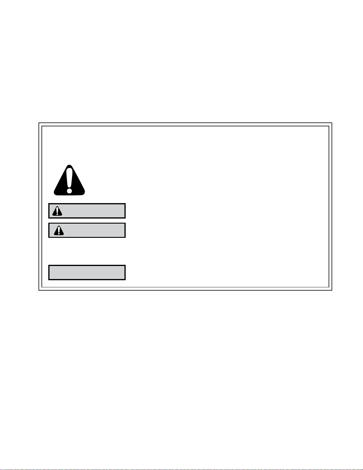
This is a safety Alert symbol.
This symbol alerts you to potential hazards that can kill or hurt you and others.
All safety messages will follow the safety alert symbol with the word “WARNING”
or “CAUTION”. These words mean:
WARNING
CAUTION
All safety messages will tell you what the potential hazard is, tell you how to reduce the chance of injury,
and tell you what will happen if the instructions are not followed.
NOTICE
You can be killed or seriously injured if you do not follow instructions.
You can receive minor or moderate injury if you do not follow instructions.
A message to alert you of potential property damage will have the
word “NOTICE”. Potential property damage can occur if instructions
are not followed.
PERSONAL INJURY OR DEATH HAZARDS
ELECTRICAL
• Unplug and/or disconnect all electrical power to the unit before performing inspections,
maintenance, or service.
• Make sure to follow proper lockout/tag out procedures.
• Always work in the company of a qualifi ed assistant if possible.
HAZARDS:
• Capacitors, even when disconnected from the electrical power source, retain an electrical charge
potential capable of causing electric shock or electrocution.
• Handle, discharge, and test capacitors according to safe, established, standards, and approved
procedures.
• Extreme care, proper judgment, and safety procedures must be exercised if it becomes necessary
to test or troubleshoot equipment with the power on to the unit.
2

• Do not spray or pour water on the return air grille, discharge air grille, evaporator coil, control panel,
and sleeve on the room side of the air conditioning unit while cleaning.
• Electrical component malfunction caused by water could result in electric shock or other electrically
unsafe conditions when the power is restored and the unit is turned on, even after the exterior is dry.
• Never operate the A/C unit with wet hands.
• Use air conditioner on a single dedicated circuit within the specifi ed amperage rating.
• Use on a properly grounded circuit only.
• Do not use extension cords with the unit.
• Follow all safety precautions and use proper and adequate protective safety aids such as: gloves,
goggles, clothing, adequately insulated tools, and testing equipment etc.
• Failure to follow proper safety procedures and/or these warnings can result in serious injury or death.
REFRIGERATION SYSTEM HAZARDS:
• Use approved standard refrigerant recovering procedures and equipment to relieve pressure before
opening system for repair
• Do not allow liquid refrigerant to contact skin. Direct contact with liquid refrigerant can result in minor
to moderate injury.
.
• Be extremely careful when using an oxy-acetylene torch. Direct contact with the torch’s fl ame or hot
surfaces can cause serious burns.
• Make sure to protect personal and surrounding property with fi re proof materials.
• Have a fi re extinguisher at hand while using a torch.
• Provide adequate ventilation to vent off toxic fumes, and work with a qualifi ed assistant whenever
possible.
• Always use a pressure regulator when using dry nitrogen to test the sealed refrigeration system for
leaks, fl ushing etc.
• Make sure to follow all safety precautions and to use proper protective safety aids such as: gloves,
safety glasses, clothing etc.
• Failure to follow proper safety procedures and/or these warnings can result in serious injury or death.
MECHANICAL HAZARDS:
• Extreme care, proper judgment and all safety procedures must be followed when testing,
troubleshooting, handling, or working around unit with moving and/or rotating parts.
• Be careful when, handling and working around exposed edges and corners of sleeve, chassis, and
other unit components especially the sharp fi
ns of the indoor and outdoor coils.
• Use proper and adequate protective aids such as: gloves, clothing, safety glasses etc.
• Failure to follow proper safety procedures and/or these warnings can result in serious injury or death.
3
PROPERTY DAMAGE HAZARDS
FIRE DAMAGE HAZARDS:
• Read the Installation/Operation Manual for this air conditioning unit prior to operating.
• Use air conditioner on a single dedicated circuit within the specifi ed amperage rating.
• Connect to a properly grounded circuit only.
• Do not use extension cords with the unit.
• Failure to follow these instructions can result in fi re and minor to serious property damage.
WATER DAMAGE HAZARDS:
• Improper installation maintenance, or servicing of the air conditioner unit, or not following the above
Safety W
• Insure that the unit has a suffi cient pitch to the outside to allow water to drain from the unit.
• Do not drill holes in the bottom of the drain pan or the underside of the unit.
• Failure to follow these instructions can result in result in damage to the unit and/or minor to serious
property damage.
arnings can result in water damage to personal items or property.
INTRODUCTION
This service manual is designed to be used in conjunction with the operation and installation manual provided
with each unit.
This service manual was written to assist the professional HVAC service technician to quickly and accurately
diagnose and repair any malfunctions of this product.
This manual, therefore, will deal with all subjects in a general nature. (i.e. All text will pertain to all models).
IMPORTANT:
It will be necessary for you to accurately identify the unit you are servicing, so
you can be certain of a proper diagnosis and repair
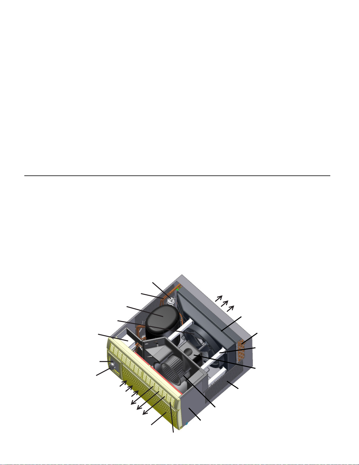
Bypass Valve
Capillary Tubes
Compressor
Fan Blade
Electrical
Compartment
On/Off Switch
Thermostat
Air Intake
Condenser
Air Discharge
. (See Unit Identifi cation.)
Condenser/Fan Blade
Shroud
Condenser Coil
Condenser
Shroud Brace
Fan/Blower
Motor
Condenser
Air Intake
Indoor Blower
Air Discharge
Front Cover
Air Discharge
Vents
4
Wheel
Sleeve
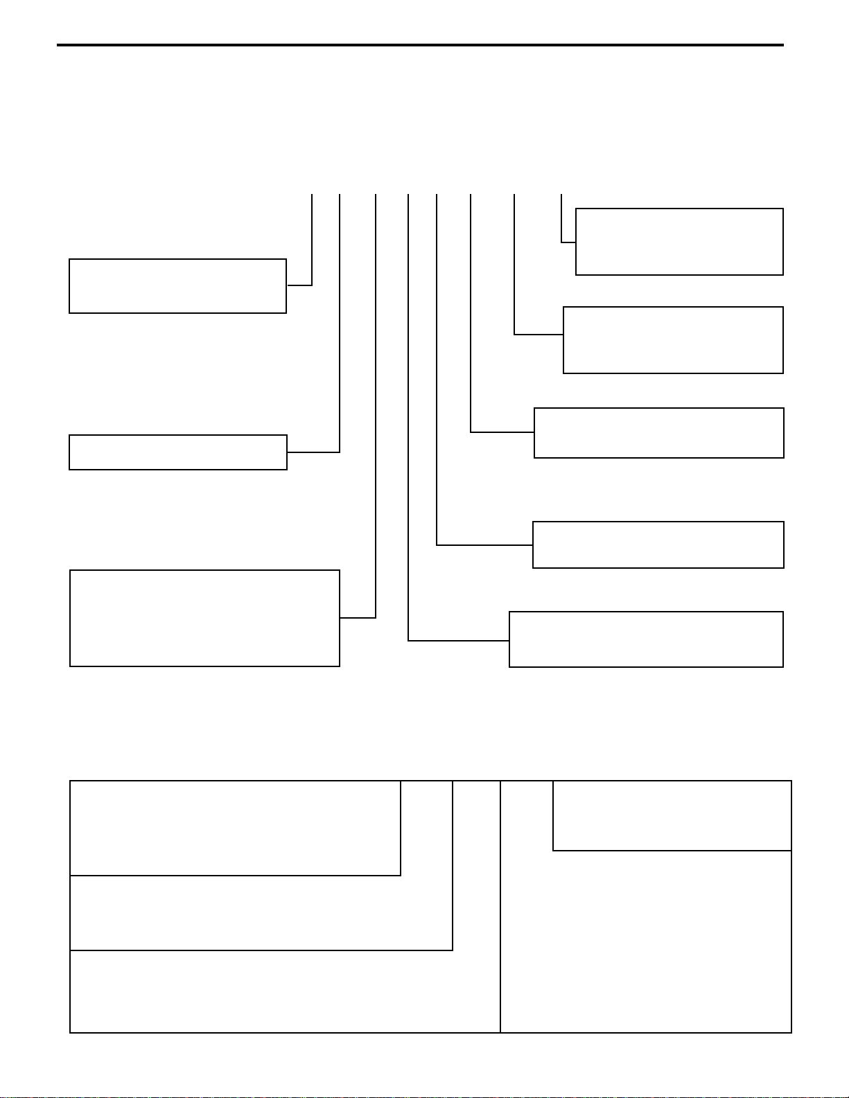
UNIT IDENTIFICATION
1st Digit – Function
S = Straight Cool, Value Series
H = HazardGard
Model Number Code
S H 15 M 3 0 A - A
8th Digit – Marketing Suffi x
Indicates Modifi cation
(Subject to change)
7th Digit – Options
0 = Straight Cool &
9th Digit – Engineering Suffi x
Indicates Modifi cation
(Subject to change)
3rd and 4th Digit - Approximate
BTU/HR (Cooling)
Heating BTU/Hr capacity listed in the
Specifi cation/Performance Data Section
RAC Serial Number Identifi
Serial Number
Decade Manufactured
L=0 C=3 F=6 J=9
A=1 D=4 G=7
B=2 E=5 H=8
Year Manufactured
A=1 D=4 G=7 K=0
B=2 E=5 H=8
C=3 F=6 J=9
6th Digit – Voltage
3 = 230-208 Volts
5th Digit - Model Series/Year Introduced
M=2010
cation Guide
A A A R 00001
Production Run Number
Product Line
R = RAC
Month Manufactured
A=Jan D=Apr G=Jul K=Oct
B=Feb E=May H=Aug L=Nov
C=Mar F=Jun J=Sept M=Dec
5
UL Listed for use in Class I, Division 2, Groups A, B, C
and D hazardous locations.
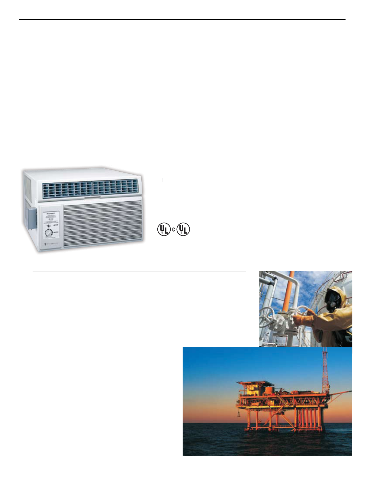
Hazardgard is specically designed to cool living qua
rters, storage areas
and other enclosures situated in hazardous locations, where specic volatile
ammable liquids or gases are handled or used within enclosed containers
or systems.
For more than 30 years, the Friedrich Hazardgard has endured some of the
toughest and most unforgiving operating conditions imaginable. Time-tested
in the eld where it counts, Hazardgard is trusted by professionals who have
to get the job done. Robust engineering with design details like 33% thicker
ns extend the life of the coil. Diamonblue
Technology, our anti-corrosive treatment,
provides added endurance and protection
in coastal or corrosive environments.
e
ch
Oshore oil rigs, on-shore oil company
ofces and reneries
Petrochemical sites and propane ll-up
stations
Paint and varnish storage or processing
plants
Grain alcohol processors or storage sites
Plant areas using strong solvents or
chemicals
Munitions plants or armories
PVC or plastics plants and processing
points
Recycling plants
Furniture renishing/stripping
workshops
Fertilizer plants
Ofce complexes where methane is a
by-product
Hazardous materials storage
Ideal applications
| HAZARDOUS DUT Y |
HAZARDGARD APPLICATION
6
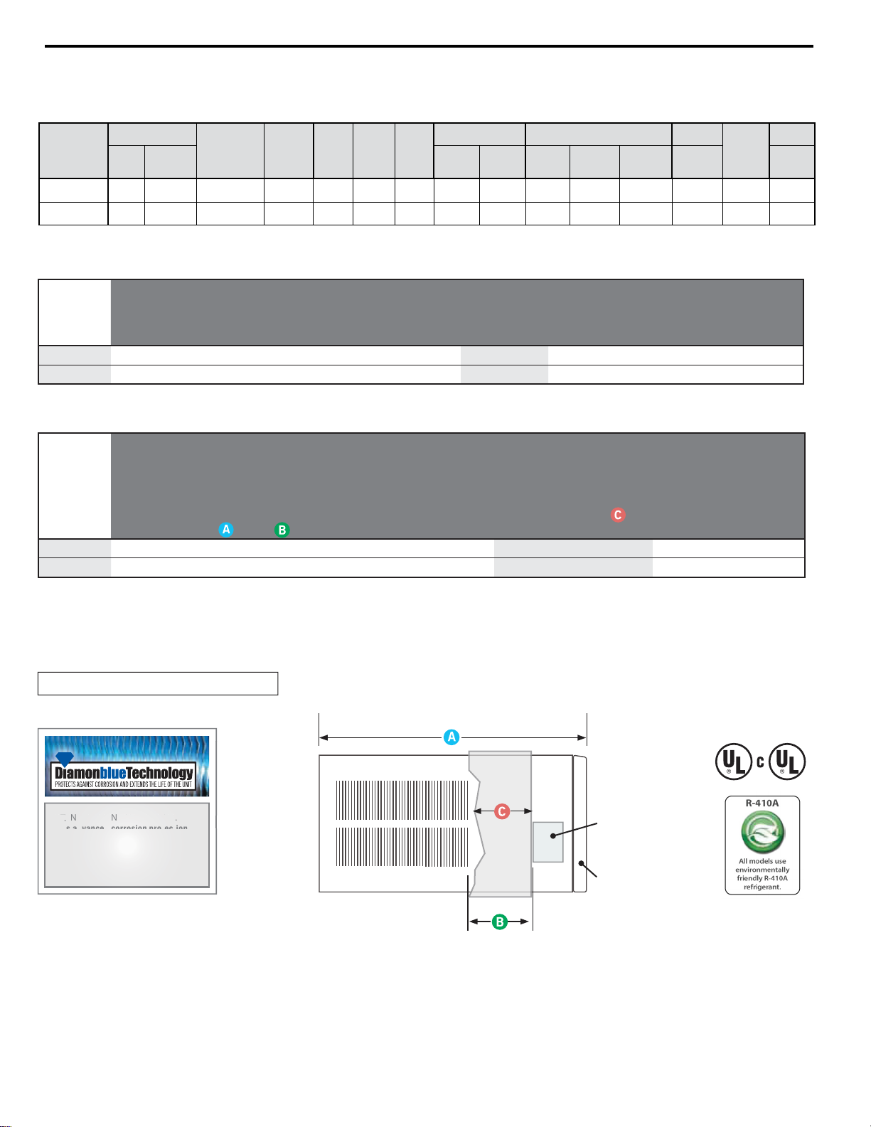
SPECIFICATIONS AND PERFORMANCE DATA
Due to continuing engineering research and technology, specL¿cations are subject to change without notice. Manufactured under U.S. Design Patent
DES 368, 306 decorative front; Utility Patent 5, 622, 058. MAXIMUM outdoor ambient operating temperature is 130°F. MAXIMUM TEMPERATURE
RATING FOR CL ASS I, DIVISION 2, GROUPS A ,B,C,D.
OPERATING TEMPERATURE CODE T3B
Specications
I
nstallation Information
Model
Cooling Capacity Electrical Characteristics (60 Hertz)
E
nergy
Efficiency
Ratio AHAM
Moisture
Removal
Air Direction
Controls
Room Side Air
Circulation
(BTU/Hr.- AHAM) Volts Rated Amps AHAM Watts EER
(Pints/ Hr.) CFM
SH15M30
*
1
4500/14000 230/208 6.9/7.4 1495/1443 9.7/9.7 6.0 8-way 375
SH20M30
*
19500/19000 230/208 9.1/10.0 2074/2021 9.4/9.4 4.0 8-way 375
Model
Dimensions
(
Inches)
Window Width
(Inches)
Thru-The-Wall
Finished Hole (Inches)
Circuit Rating
Breaker or
T - D Fuse
Weight
(Lbs.)
Height Width
Depth
Overall
Depth J Box
to Louvers
Minimum
Extension
Into Room
Minimum
Extension
Outside Min. Max. Height Width Max. Depth Volts - Amps Net Shipping
SH15M30
*
15
15
/
16 25
15
/
16 27
3
/
8 6 3
1
/
16 16
15
/
16 27
7
/
8 42 16
3
/
16 26
3
/
16 6 250V - 15A 156 168
SH20M30
*
17
15
/
16 25
15
/
16 27
3
/
8 6 3
1
/
16 16
15
/
16 27
7
/
8 42 18
3
/
16 26
3
/
16 6 250V - 15A 160 174
(A)
Front
SIDE VIEW
(A)
Junction
Box
Max.
Wall
Depth
S TANDA RD ON A LL M ODEL S .
This advanced corrosion pro tection
treatment protects the outdoor coil
against deterioration and extends
the life of the unit especially in harsh
coastal environments.
TAA
A
All models use
environmentally
friendly R-410A
refrigerant.
R-410A
Cooling Performance Data
EVAPORATOR AIR
TEMP. DEG. F
Discharge
Temp. Drop F. Suction Discharge Amps Cool Amps Heat
Air
SH15M30
SH15M30
Due to continuing research in new energy-saving technology, performance data and 8th and 9th character are subject to change without notice.
*
54 26 127 186 67 18 35 137 480 6.9 - 43 50 208 / 230 15
*
54 26 185 124 68 15 38 137 485 9.1 - 43 42.7 208 / 230 15
*
CONDENSER
TEMPERATURE
DEG. F
*
Discharge
Temp
Suction
Temp
Super
Heat
Sub-
Cooling
OPERATING
PRESSURES
ELECTRICAL RATINGS R-410A REF.
Locked Rotor
Amps
Charge in OZ.
Voltage
BREAKER
FUSE
60 Hertz
Amps
7
7
ELECTRICAL DATA
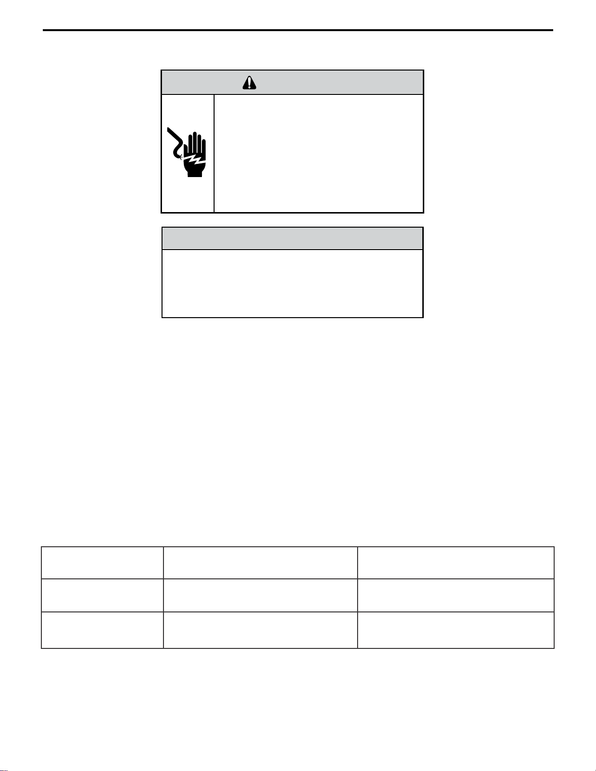
Not following the above WARNING could result in fi re or
electrically unsafe conditions which could cause moderate
or serious property damage.
Read, understand and follow the above warning.
WARNING
ELECTRIC SHOCK HAZARD
Turn off electric power before service or
installation.
All electrical connections and wiring MUST be
i
nstalled by a qualifi ed electrician and conform to
the National Electrical Code and all local codes
which have jurisdiction.
Failure to do so can result in personal injury or
death.
NOTICE
FIRE HAZARD
ELECTRICAL REQUIREMENTS
ALL FIELD WIRING MUST MEET THE REQUIREMENTS OF THE NATIONAL ELECTRICAL CODE (ANSI/NFPA 70)
ARTICLE 501.
THE FIELD-PROVIDED CIRCUIT PROTECTION DEVICE (HACR CIRCUIT BREAKER OR TIME DELAY FUSE)
MUST NOT EXCEED THE AMPACITY INDICATED ON THE PRODUCT NAMEPLATE.
IMPORTANT: Before you begin the actual installation of your air conditioner, check local electrical codes and the
information below.
Your air conditioner must be connected to a power supply with the same A.C. voltage and frequency (hertz) as marked
on the data plate located on the chassis. Only alternating current (A.C.), no direct current (D.C.), can be used.
An overloaded circuit will invariably cause malfunction or failure of the air conditioner therefore, it is extremely important
that the electrical power is adequate. Consult your power company if in doubt.
Model Number Connection Type
SH15 Junction Box 250V-15 Amp
Circuit Rating
Time Delay Fuse
SH20 Junction Box 250V-15 Amp
8
HAZARDGARD SPECIAL FEATURES
Permanent Split-Capacitor, totally enclosed fan motor
• •
to assure effi cient operation even under adverse
electrical conditions. Motor has a special stainless
steel shaft to resist corrosion and a hermetically sealed
overload for arc-free operation.
•
High capacity compressor with internal hermetically
sealed overload.
•
Solid-state relay contains transient voltage suppressor
to protect controls against transient voltage spikes.
Provides solid state switches for arc-free operation.
•
Hot gas bypass low ambient control to permit operation
without freezing at outdoor ambient temperatures as
low as 45°F (7°C).
•
Environmentally sealed on-off switch and gold plated
contacts in thermostat for corrosion resistance.
•
Electrodeposited epoxy primer and alkyd enamel, both
oven-baked for an attractive, long-lasting fi nish.
Copper tubing/aluminum fi n coils.
•
Galvanized steel cabinet and base pan, all bonderized.
•
Slide-out chassis for easy installation in window or
through–the–wall.
•
Extra insulation inside, including completely insulated
plenum chamber for quieter, more effi cient cooling.
•
Entire unit test run in environmental chamber before
crating.
•
Eight–way air fl ow control for uniform air circulation.
•
Condensate drain with exclusive mosquito trap.
•
15 amp circuit with time-delay fuse required.
Accommodates direct wiring.
Long lasting 3/8” (10mm) thick air fi lter, germicidally
•
treated, easily removed for cleaning.
Friedrich Air Conditioning quality has been proven by more than 25 years of successful experience from the Gulf
of Mexico to the searing sands of the Arabian desert.
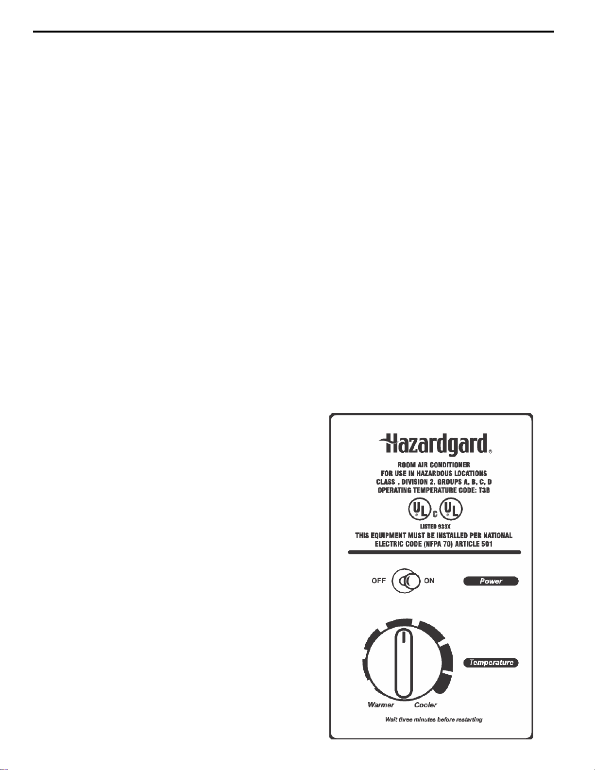
Control Panel
Function Control (Power)
This switch is a double pole, single throw toggle switch.
ON -
Turns everything on.
(Fan motor runs continuously)
OFF - Turns everything off.
Temperature Control
The knob at the bottom is the thermostat which is a cross
ambient
The thermostat reacts only to a change in temperature at
the bulb location - turn the knob clockwise to set cooler,
counterclockwise for warmer.
Ex
Friedrich leads with the fi rst UL Listed Room Air
Conditioners designed to cool living quarters and other
enclosures situated in hazardous locations where specifi c
volatile fl ammable liquids or gases are handled or used with
enclosed containers or systems. Friedrich Hazardgard
room air conditioners are designed to meet the National
Electrical Code, Article 500 requirements for Class
I, Division 2, Groups A, B, C, D Hazardous locations,
and are the only air conditioners UL Listed for this
application. THIS UNIT IS LISTED BY UNDERWRITERS
LABORATORIES FOR USE IN CLASS I, DIVISION
2,GROUPS A, B, C, D HAZARDOUS LOCATIONS.
Operating Temperature Code: T3B.
type used to maintain the desired comfort level.
clusive
9

COMPONENT DEFINITIONS
A. Mechanical components
Plenum assembly
Diffuser with directional louvers used to direct the conditioned airfl
Blower wheel
Attaches to the indoor side of the fan motor shaft and is used for distributing unconditioned, room side air through
the heat exchanger and delivering conditioned air into the room.
Slinger fan blade
Attaches to the outdoor side of the fan motor shaft and is used to move outside air through the condenser coil, while
slinging condensate water out of the base pan and onto the condenser coil, thus lowering the temperature and
pressures within the coil.
B. Electrical components
Thermostat Control
Used to maintain the specifi ed room side comfort level.
System Switch
Used to regulate the operation of the fan motor and the compressor or to turn the unit off. For troubleshooting, refer
to the wiring diagrams and schematics in the back of this service manual.
ow.
Solid State Relay
Used to energize the compressor and fan motor. Each unit has 2, 50 amp, 208/230 volt relays.
Capacitor
Reduces line current and steadies the voltage supply, while greatly improving the torque characteristics of the fan
motor and compressor motor
.
Fan Motor
Dual shafted fan motor operates the indoor blower wheel and the condenser fan blade simultaneously. (When unit
is turned on, the fan motor runs continuously).
C. Hermetic components
Compressor
Motorized device used to compress refrigerant through the sealed system.
Low ambient bypass (hot gas bypass) valve
Used for low ambient cooling operation, the valve is connected between the discharge line at the compressor and
the
suction process tube. It responds to suction pressure, whcih when reduced in the system, causes the valve to
open and bypass hot gas from the high pressure side to the low pressure side of the system. The valve is preset
to open when the suction pressure reaches 88 psig.
Capillary tube
A cylindrical metering device used to evenly distribute the fl ow of refrigerant to the heat exchanger (evaporator
coils).
10
 Loading...