

Page 1
INSTALLATION INSTRUCTIONS
FOR "SC" MODELS
CASEMENT SASH WINDOW INSTALLATIONS.
These models will fit casement window openings as follows:
HEIGHT : 10-13/16" Minimum to 1 1-3/4" Maximum
WIDTH: 14-3/4" Minimum to 18-3/8" Maximum
STEP 1 Remove the unit from the shipping carton. Remove the tape holding the decorative front in place.
Remove the front and place it out of the way . Slide the unit out of the shell. As you slide the unit out,
you will notice a foam gasket between the chassis and the cabinet. Save the gasket for STEP 7.
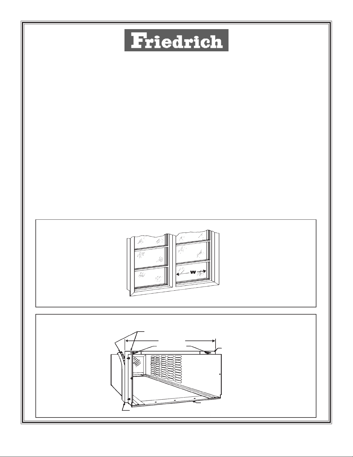
STEP 2 Remove the glass, putty and window crank, if necessary . Measure the horizontal width dimension “W”
or window frame opening (Figure 1). If dimension “W” is 16" (405 mm) or less, no adjustment of the
side bracket is necessary. If the dimension is more than 16" (405 mm) – loosen the two (2) acorn nuts
and slide the side brackets out. (Add one inch (25 mm) to the measured “W” dimension for this
adjustment.) Tighten the acorn nuts. (Figure 2).
FIGURE 1
FIGURE 2
ATTACH GASKETS TO BACKSIDE
OF THE BRACKETS AT THE TOP AND SIDES.
W+1"
ACORN NUT
SILL CHANNEL
SIDE BRACKET
SIDE BRACKET
RACINST4 (7/97) Page 1
Page 2
STEP 3 Remove the paper backing from the 36" (91 mm) strip of foam gasket (3/8" x 3/4"(10 mm x 19mm)) and attach
it to the back side of the top and side brackets (Figure 2). The edge of the gasket and brackets should be
flush. Press the gasket firmly in place.
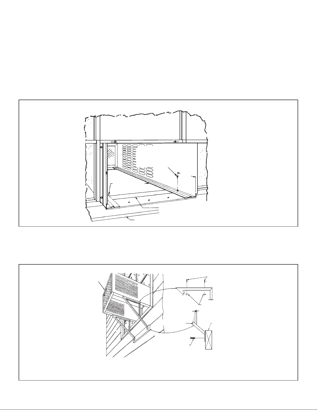
STEP 4 Slide the outer shell into the window opening as far as the sill channel will permit. The back side of the sill
channel must be in contact with the front side of the window frame (Figure 3). Drill two (2) 9/64" (3.6mm)
diameter pilot holes in the lower part of the window frame.
NOTE: Use the first empty hole in the bottom side rails of the shell, just back of the steel sill channel as a
guide. Secure the shell to the window channel with two (2) hex-head self-tapping screws 1-1/8"
(29 mm) long in the pilot holes. Part # 906-022-02 (Figure 3).
FIGURE 3
DRILL TWO 9/64" PILOT
HOLES IN THE WINDOW
AND INSTALL 2 SCREWS.
1-1/2"
(38 mm)
BOTTOM SIDE
RAIL
SILL CHANNEL NEXT TO WINDOW
FRAME.
WINDOW SILL
STEP 5 Position the support brackets as shown in Figure 4. Attach to the shell with four (4) truss-head 10-24 machine
screws and four (4) flat nuts. Secure the bottom of the support brackets to the wall with two (2) wood screws.
Check the shell to allow for a 1/4" (6 mm) downward slope towards the outside. If used on other than wood
construction, screw the support brackets to a piece of 2" x 4" material.
MACHINE SCREW 10-24 X 1"
FIGURE 4
NOTE: ADJUST THE
SUPPORT BRACKETS TO
PROVIDE A 1/4" (6 mm) DROP
OF THE SHELL TO THE
OUTSIDE FOR WATER
DRAINAGE. THIS VIEW
SHOWS THE SHELL
MOUNTED IN THE WINDOW.
THE SUPPORT BRACKETS
ARE ASSEMBLED THE SAME
FOR A THRU-THE-WALL
INSTALLATION.
SHELL
SUPPORT
BRACKET
SECURE THE
LOWER END OF THE
SUPPORT TO THE WALL
WITH TWO SHEET METAL
SCREWS 12A X 2" LONG
(PART #906-011-08) DRILL
5-32" PILOT HOLES.
(#906-067-00,4 REQ’D.)
FLAT NUT
910-026-00 (4 REQ’D.)
2" X 4" LUMBER (IF NEEDED)
Page 2 RACINST4 (7/97)
Page 3
STEP 6 If the installation is in the swing-out part of the window , be sure the window is locked closed, then slide the
chassis into the shell as far as it will go.
STEP 7 Reinstall the CHASSIS SEAL GASKET. Carefully "stuff" the gasket between the chassis and the cabinet
starting at either bottom corner and go up the side, across the top and down the opposite side. It is
IMPORTANT that this gasket be properly installed as it prevents air leakage around the chassis.
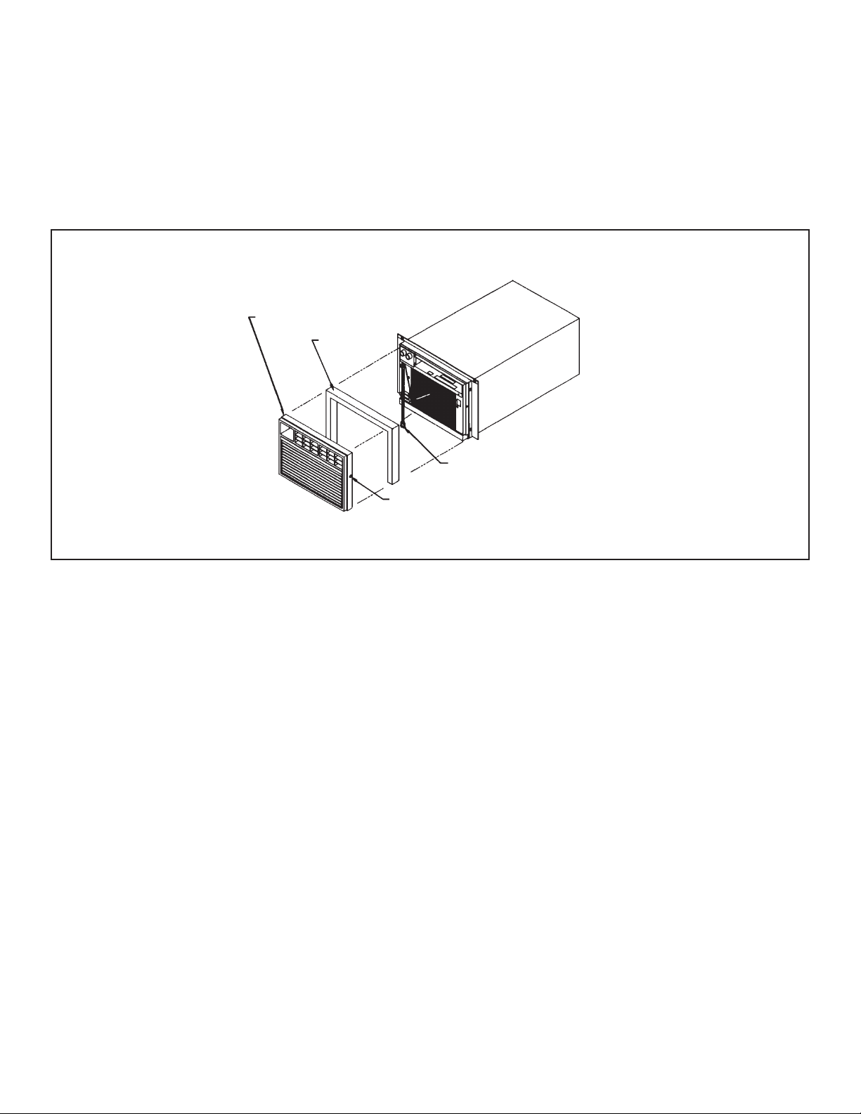
STEP 8 Place the filter in the pocket, in front of the coil, then install the decorative front over the edge of the shell and
secure it with two (2) number 10 x 1/2" slotted head screws, (Figure 5).
FIGURE 5
DECORATIVE FRONT
CHASSIS
SEAL
SERVICE CORD EXITS FROM A NOTCH IN THE BOTTOM
OF THE DECORATIVE FRONT
SLOTTED TRUSS–HEAD SCREW ON EACH SIDE OF THE
DECORATIVE FRONT
STEP 9 CIRCUIT PROTECTION – If the air conditioner is connected to a circuit protected by a fuse, use a “TIME-
DELA Y” fuse due to the momentary high current demand when the air conditioner is started. Before operating
your unit, verify the ampere rating of the time-delay fuse or circuit breaker which protects your unit. The
ampere rating of the time-delay fuse or circuit breaker must be 15 amps. Plug the service cord into the
electrical outlet (see warning note below). Refer to the Owner’s Manual for operating instructions.
WARNING: This appliance is equipped with a three-prong (grounding) plug for your protection against shock
hazards and should be plugged directly into a properly grounded three-prong receptacle.
Where a two-prong receptacle is encountered, it must be replaced with a properly grounded
three-prong receptacle in accordance with the National Electrical Code and local codes and
ordinances. The work should be done by a qualified electrician.
RACINST4 (7/97) Page 3
Page 4

THRU–THE–WALL INSTALLATIONS
Hardware included for installation:
2 - Support brackets
2 - No. 12A x 2" Sheet Metal Screws
4 - 10-24 x 1" Machine Screws
4 - 10-24 Flat Nuts
1 - 36" Strip Foam Gasket (Part # 604-673-32)
STEP 1 Remove the unit from the shipping carton. Remove the tape holding the decorative front in place. Remove the
front and place it out of the way. Slide the unit out of the shell. As you slide it out, you will notice a foam gasket
between the chassis and the cabinet. Save this gasket for STEP 6.
STEP 2 LAYOUT: Cut and frame-in an opening in the desired wall area, using Figure 6 as a guide. Remove two (2)
screws and relocate the sill plate back one inch to the next set of holes in the shell rail. Place the shell in the
wall opening with the front flange tight against the wall surface. Drill three (3) 3/32" (2.5 mm) diameter pilot
holes. Secure three (3) 1-1/4" long Phillips screws in the sill plate (Figure 7).
2 - 10BP x 1/2" Slotted Truss Head Screws
3 - 8A x 1 1/4" Phillips Head Screws
2 - 8-32 x 1-1/8" Hex Head Self-Tapping Screws
NOTE: This unit may be installed in walls up to 9"
thick (maximum).
FIGURE 6
FINISHED HOLE SIZE
2" x 8" FRAME
FINISHED HOLE
SIZE
FRAME CONSTRUCTION
CONCRETE BLOCK CONSTRUCTION
STEP 3 Attach the support brackets to the shell with screws and nuts furnished (See Figure 4 - Sash Window
Installations).
STEP 4 Secure the lower end of the support brackets to the wall. (See Figure 4 - Sash Window Installations.)
NOTE: If other than wood construction, use a piece of 2" x 4" lumber to attach support brackets. (See Figure
4 - Sash Window Installations.)
STEP 5 Caulk all around the shell on the outside to insure
a watertight seal. Slide the chassis into the shell
FIGURE 7
as far as it will go.
INTERIOR WALL SURFACE
STEP 6 Reinstall the CHASSIS SEAL GASKET . Carefully
SHELL
stuff the gasket between the chassis and the
cabinet, starting at either bottom corner and go up
the side, across the top and down the opposite
side. It is IMPORTANT that this gasket be
SCREW
(8A X 1-1/4"
properly installed as it prevents air leakage
around the chassis.
STEP 7 Complete the installation by following STEPS 8
and 9 of the Sash Window Installation
Instructions, Page 3.
Page 4 RACINST4 (7/97)
SILL CHANNEL RELOCATED 1" BACK TO THE
NEXT SET OF HOLES
 Loading...