

Page 1
EMRT1
Energy Management Wired
Thermostat
Sensor
INSTRUCTION MANUAL
PART NO. 94993003_01
with an Occupancy
Page 2

Page 3

Table of Contents
Introduction ............................................................................................................ 5
Before You Begin ...................................................................................................6
Programming a Thermostat with a Network Programmer ..................................... 7
Thermostat Installation .......................................................................................... 8
Thermostat Conguration ...................................................................................... 9
Setting the thermostat clock ................................................................................ 10
Entering the room number ................................................................................... 11
Conguring the Equipment Settings - Compressor Type ....................................12
Conguring the Equipment Settings - Electric Heat ............................................ 13
Conguring the Equipment Settings - Reversing Valve .......................................14
Conguring the Energy Saving Settings ............................................................. 15
Testing the thermostat ......................................................................................... 16
Accessing the Thermostat Settings ..................................................................... 17
Custom Energy Savings Settings ........................................................................ 17
Using the Thermostat Settings Screens .............................................................. 18
01 – FAN CONTROL MODE ...............................................................................19
ST
STAGE DIFFERENTIAL - HEAT ............................................................20
02 – 1
ND
STAGE DIFFERENTIAL - HEAT ............................................................21
03 – 2
04 – 1ST STAGE DIFFERENTIAL - COOL .........................................................22
05 – INCIDENTAL OCCUPANCY THRESHOLD .................................................23
06 – NIGHT OCCUPANCY THRESHOLD ........................................................... 24
07 – FORCED 2ND STAGE HEATING................................................................ 25
08 – NIGHT OCCUPANCY START .....................................................................26
09 – NIGHT OCCUPANCY END ......................................................................... 27
10 – TEMPERATURE RECOVERY TIME ........................................................... 28
11 – RECOVERY TEMPERATURE - HEAT ........................................................ 29
12 – TEMPERATURE SETBACK DELAY - HEAT ............................................... 30
13 – MINIMUM SETBACK TEMPERATURE ......................................................31
14 – TEMPERATURE SETBACK DELAY - COOL .............................................. 32
15 – MAXIMUM SETBACK TEMPERATURE......................................................33
16 – RECOVERY TEMPERATURE - COOL .......................................................34
17 – MINIMUM SET POINT.................................................................................35
3
Page 4

Table of Contents
18 – MAXIMUM SET POINT ...............................................................................36
19 – TEMPERATURE CONTROL MODE ........................................................... 37
20 – AUTO CHANGEOVER SET POINT OFFSET ............................................. 38
21 – SETBACK SET POINTS / AUTO-RESTORE .............................................. 39
22 – AUTOMATIC HUMIDITY CONTROL
22 – TEMPERATURE CALIBRATION ................................................................. 41
Troubleshooting ................................................................................................... 42
Error Codes ......................................................................................................... 42
APPENDIX 1 - Energy Saving Presets................................................................ 44
APPENDIX 2 - Glossary ...................................................................................... 45
Warranty Information ........................................................................................... 46
Technical Specications ...................................................................................... 48
†
.......................................................... 40
4
Page 5

Introduction
Friedrich EMRT1 Energy Management Thermostats for the hospitality industry
deliver unprecedented energy savings without compromising guest comfort.
Integrated occupancy sensor uses a combination of motion and thermal sensing
technologies for accurate occupancy detection. Reliable occupancy detection
allows saving energy when rooms are unoccupied.
Energy saving presets eliminate the guesswork and make it easy to adjust the
energy saving settings. (Patent Pending)
Fully congurable energy saving settings allow customizing the thermostat
energy saving settings to t any situation.
Comprehensive conguration options ensure full compatibility with virtually
any existing or emerging hospitality HVAC system with up to 2 heat and 1 cool
stages.
Built-in wireless mesh-networking enables optional remote management.
For installation of a networking thermostat with remote management, refer to the
“Network Installation” manual.
5
Page 6

Before You Begin
➤ Determine the appropriate installation location for the thermostat. The
thermostat should face the bed area of the room.
➤ Set the PTAC/Vert-I-Pak unit to “External Thermostat” (Class 2) mode.
Consult the PTAC/Vert-I-Pak unit documentation to determine how to set
the PTAC/Vert-I-Pak unit to “External Thermostat” mode.
6
Page 7
Before You Begin
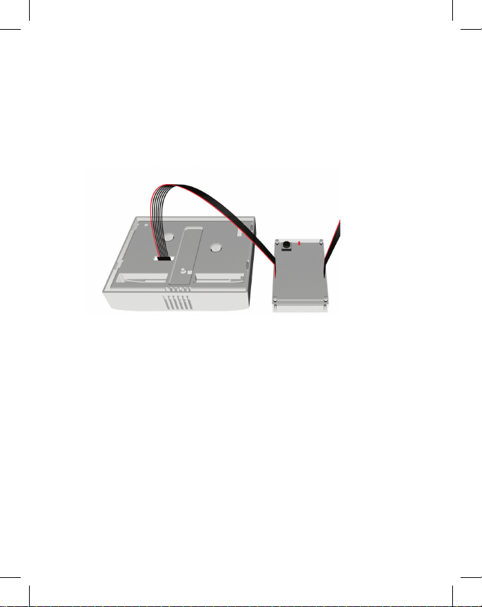
Programming a Thermostat with a Network Programmer
In case of Network Installation with Remote Management, the thermostat must
be programmed with a Network Programmer specic to the property before the
installation.
Thermostat must not be powered during the pairing procedure..
➤ Plug one programmer connector into the thermostat;
➤ Push the black button on the programmer. The red light on the programmer
should turn on and remain steadily lit;
If the red light on the programmer is blinking or is not steadily lit, unplug the
programmer from the thermostat and repeat the steps above.
➤ Unplug the programmer from the thermostat;
7
Page 8
Thermostat Installation
➤ Set the PTAC unit to “External Thermostat” (Class 2) mode.
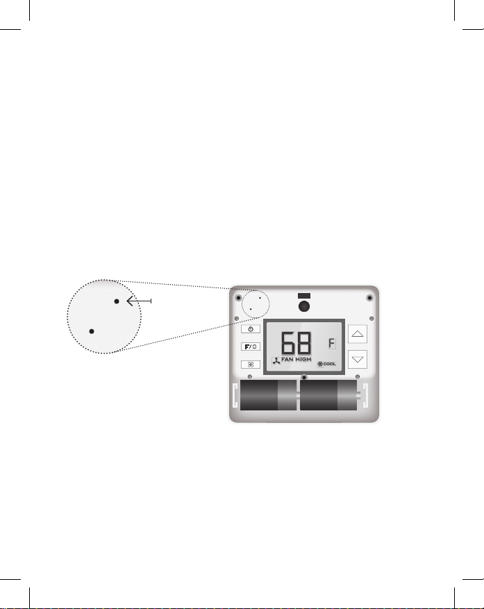
Mounting the thermostat to the wall
➤ Unplug the PTAC/Vert-I-Pak unit;
➤ Remove the thermostat cover;
➤ Connect the thermostat wires to the supplied Wiring Connector - refer to
the Wiring Table to determine proper connections;
➤ Plug in the wiring connector into to the thermostat;
➤ Use the supplied wall anchors and mounting screws to secure the
thermostat to the wall;
➤ Follow the “Thermostat Conguration” instructions;
➤ Replace the thermostat cover and screw in the locking screw;
➤ Plug in the PTAC/Vert-I-Pak unit.
Wiring Table - 24V AC
Wire
Terminal
Color
Black C Common
Red R 24V
Yellow Y Compressor
White W Heat
Orange O or B Reverse Valve
Green GH Fan High
Purple GL Fan Low
NOTE: If the PTAC/Vert-I-Pak unit has only one (1) fan speed, connect both fan
control wires – Green and Purple – to the fan terminal (G).
8
Letter
Terminal
Connection
Wiring Table - 24V DC
Wire
Terminal
Color
Black R 24V
Red C Common
Yellow Y Compressor
White W Heat
Orange O or B Reverse Valve
Green GH Fan High
Purple GL Fan Low
Letter
Terminal
Connection
Page 9
Thermostat Con guration
Once the thermostat is powered, thermostat con guration settings will appear on
the thermostat screen.
In order to properly operate the PTAC/Vert-I-Pak unit:
➤ Set the thermostat clock;
➤ Enter the room number;
➤ Con gure the equipment settings;
➤ Select Energy Savings Preset;
The thermostat con guration screens have a 3-minute time-out. If no action is
taken within three (3) minutes, the thermostat will exit con guration settings.
CONFIGURATION
BUTTON
NOTE: You can access Thermostat Con gu-
ration settings at any time by pressing the
“Con guration” button.
9
Page 10
Thermostat Con guration
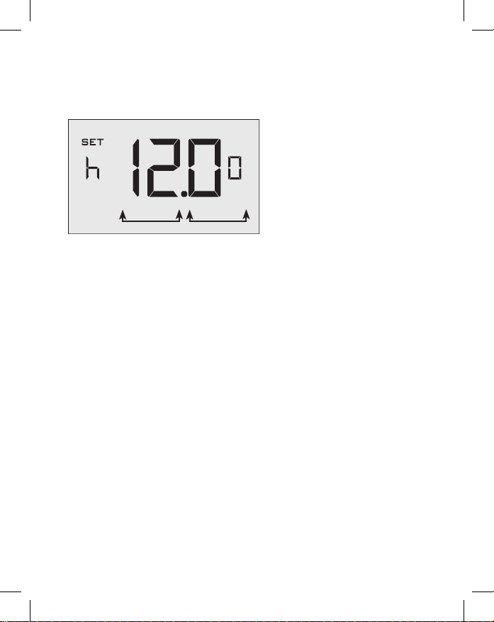
Setting the thermostat clock
HOURS MINUTES
Set the thermostat clock to current time in 24h (Military Time) format.
➤ Use the “Up” and “Down” buttons to set the hours;
➤ Press the “Fan” button to advance to the minutes setting;
➤ Use the “Up” an “Down” buttons to set the minutes;
➤ Press the “F/C” button to advance to the next menu;
Setting the clock correctly is crucial for proper operation of the thermostat.
10
Page 11
Thermostat Con guration
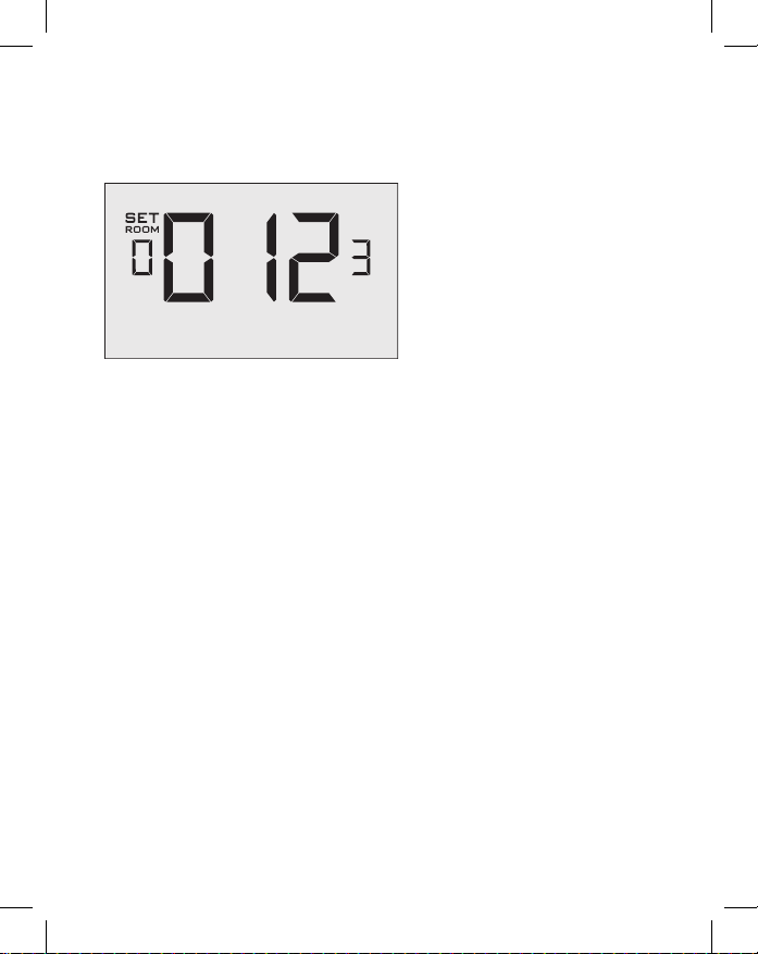
Entering the room number
Enter the room number by changing the digits on the screen. Leading zeros “0”
preceding other digits will be ignored, i.e. Room number “123” should be entered
as “00123”.
➤ Use the “Up” and “Down” buttons to change the digit;
➤ Press the “Fan” button advance to the next digit;
➤ Press the “F/C” button to advance to the next menu;
Entering the room number correctly is crucial for proper operation of remotely
managed thermostats.
11
Page 12

Thermostat Con guration
Con guring the Equipment Settings - Compressor Type
COMPRESSOR TYPE
➤ Use the “Up” and “Down” buttons to change the compressor type by
changing the rst digit;
0 No Compressor
1 Heat Pump
2 * Air Conditioner
➤ Press the “Fan” button to advance to the next setting;
* Indicates default setting;
12
Page 13

Thermostat Con guration
Con guring the Equipment Settings - Electric Heat
ELECTRIC HEAT
➤ Use the “Up” and “Down” buttons to change the Electric Heat setting by
changing the second digit;
0 No Electric Heat
1 * Electric Heat
➤ Press the “Fan” button to advance to the next setting;
* Indicates default setting;
13
Page 14
Thermostat Con guration
Con guring the Equipment Settings - Reversing Valve
REVERSING VALVE
➤ Use the “Up” and “Down” buttons to change the Reversing Valve setting by
changing the third digit;
0 OB contact is energized to cool;
1 * OB contact is energized to heat;
Refer to the PTAC unit documentation to determine the correct OB
VALVE setting.
If incorrect OB VALVE Setting is selected, the PTAC unit will turn on
the heating when air conditioning is requested and turn on the air
conditioning when heating is requested;
➤ Press the “Fan” button to advance to the next setting;
➤ Press the “F/C” button to advance to the next menu;
* Indicates default setting;
14
Page 15

Thermostat Con guration
Con guring the Energy Saving Settings
➤ Use the “Up” and “Down” buttons to select the Energy Saving preset:
E-0* Energy Savings Off - No Temperature Setback;
E-1 Lowest Energy Savings;
E-2 Lower Energy Savings;
E-3 Standard Energy Savings;
E-4 Higher Energy Savings;
E-5 Highest Energy Savings;
Refer to the APPENDIX 1 for Energy Saving Preset details.
E-C Indicates “Custom Energy Savings Settings” in case the active
➤ Press the “Power” button to save the Thermostat Con guration and start
thermostat savings settings differ from any Energy Saving preset;
For details, refer to the “Custom Energy Savings Settings” section;
using the thermostat;
* Indicates default setting;
15
Page 16

Thermostat Conguration
Testing the thermostat
Following the thermostat conguration, test if the thermostat is controlling the PTAC
unit.
➤ Press the “Power” button to turn the thermostat ON;
➤ Press the “Up” and “Down” buttons to change the temperature set point
above and below the current room temperature to test if the thermostat
initiates heating and cooling - the PTAC unit should turn heating and air
conditioning on and off.
➤ Change the fan speed by touching the “Fan” button to test if the thermostat
is controlling the fan speed.
16
Page 17

Custom Energy Savings Settings
If you don’t want to use the one of the energy saving presets listed on page
17 and detailed in the Appendix 1, you can enter the custom energy savings
settings.
Accessing the Thermostat Settings
➤ Press and hold the “Con guration” button until the rst thermostat settings
screen appears.
The thermostat must be turned on to access the thermostat settings.
CONFIGURATION
BUTTON
NOTE: You can access Thermostat
Settings by pressing and holding the
“Con guration” button.
17
Page 18

Custom Energy Savings Settings
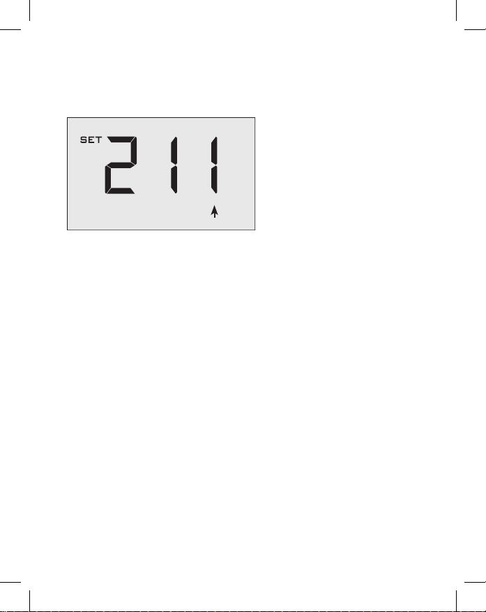
Using the Thermostat Settings Screens
SETTING VALUE
SCREEN NUMBER
➤ Use the “Up” and “Down” buttons to change the setting;
➤ Press the “F/C” button to advance to the next setting;
➤ Press the “Fan” button to return to the previous setting;
➤ Press the “Power” button to save and exit thermostat settings;
18
Page 19

Custom Energy Savings Settings
01 – FAN CONTROL MODE
Select Fan Control Mode:
00 MANUAL - guest can select automatic or continuous fan mode;
01 * AUTOMATIC - fan runs only when there is a demand for heating or
* Indicates default setting;
air conditioning;
19
Page 20

Custom Energy Savings Settings
02 – 1ST STAGE DIFFERENTIAL - HEAT
02-30 (0.2°F - 3.0°F; 0.5°F* default setting) Select the number
of degrees the thermostat has to sense between the automatic
changeover temperature for heat and the room temperature before a
call for the 1st stage heating is initiated.
20
Page 21

Custom Energy Savings Settings
03 – 2ND STAGE DIFFERENTIAL - HEAT
10-20 (1.0°F - 2.0°F*; 2.0°F* default setting) Select the
difference between 1st stage heating and 2nd stage heating initiation.
21
Page 22

Custom Energy Savings Settings
04 – 1ST STAGE DIFFERENTIAL - COOL
02-30 (0.2°F - 3.0°F; 0.5°F* default setting) Select the number
of degrees the thermostat has to sense between the automatic
changeover temperature for cool and the room temperature before a
call for the 1st stage cooling is initiated.
22
Page 23

Custom Energy Savings Settings
05 – INCIDENTAL OCCUPANCY THRESHOLD
00-60 (05* default setting) Select the minimum period of time (in
minutes) for which occupancy needs to be detected to enter the guest
occupancy mode.
When occupancy is detected, thermostat will switch to occupied
mode for a duration of “Incidental Occupancy Threshold” selected
here.
If occupancy is detected for a period of time shorter than the
“Incidental Occupancy Threshold” selected here, the thermostat will
automatically revert to unoccupied mode at the end of the “Incidental
Occupancy Threshold” period and continue to observe energy saving
functions that were in effect before the room became occupied. This
setting allows ignoring incidental room visits.
If occupancy is detected for a period of time longer than the
“Incidental Occupancy Threshold” selected here, the thermostat will
enter the guest occupancy mode. When the thermostat is in the guest
occupancy mode, it will revert to unoccupied mode and initiate the
setback temperature only when occupancy is not detected for the
duration of the setback delay (Heat or Cool) period.
23
Page 24

Custom Energy Savings Settings
06 – NIGHT OCCUPANCY THRESHOLD
00-60 (01* default setting) Select the minimum period of time
(in minutes) for which occupancy needs to be detected in order to
consider the room occupied during the “Night Occupancy”period.
When occupancy is detected during the “Night Occupancy Period”
for longer than the “Night Occupancy Threshold” selected here, the
thermostat will instantaneously switch to occupied mode.
If occupancy is detected for a period of time shorter than the
“Night Occupancy Threshold” selected here, the thermostat will
automatically revert to unoccupied mode and continue to observe
energy saving functions that were in effect before the room became
occupied.
If occupancy is detected for a period of time longer than the “Night
Occupancy Threshold” selected here, the thermostat will disable the
occupancy sensor and consider the room occupied until the end of
the “Night Occupancy” period.
This feature ensures that energy saving functions that may affect
guest comfort will not come in effect during the “Night Occupancy”
period.
24
Page 25

Custom Energy Savings Settings
07 – FORCED 2ND STAGE HEATING
00-60 (30* default setting) Select a number of minutes 1st stage
heating will run before 2nd stage heating is automatically initiated if
the guest set point is not reached and the 2nd stage heating is not
initiated through differential settings.
This feature allows automatically turning on 2nd stage heating to
avoid excessive compressor use.
00 to disable the feature.
Set to
25
Page 26

Custom Energy Savings Settings
08 – NIGHT OCCUPANCY START
00-23 (21* default setting) Select the start time (in hours - 24-
hour clock) for “Night Occupancy”
If occupancy is detected for a period of time longer than the “Night
Occupancy Threshold” during “Night Occupancy” period, the
thermostat will disable the occupancy sensor and consider the room
occupied until the end of the “Night Occupancy” period.
This feature ensures that energy saving functions that may affect
guest comfort will not come in effect during the “Night Occupancy”
period if room was occupied for a period of time longer than “Night
Occupancy Threshold”.
26
Page 27

Custom Energy Savings Settings
09 – NIGHT OCCUPANCY END
00-23 (09* default setting) Select the time (in hours - 24-hour
clock) for “Night Occupancy” to end.
The time of day the “Night Occupancy” ends and the thermostat
switches back to the room sensing settings chosen in the other
occupancy modes.
27
Page 28

Custom Energy Savings Settings
10 – TEMPERATURE RECOVERY TIME
00-60 (25* default setting) Select the maximum time allowed
for a PTAC unit to attain temperature as de ned by Heat and Cool
“Recovery Temperature”;
“Temperature Recovery Time” selected here and the actual
temperature recovery ability of the PTAC unit are used to calculate
setback temperatures. Calculated setback temperatures maximize
energy savings and at the same time ensure that a comfortable room
temperature (de ned as Heat and Cool “Recovery Temperature”) will
be restored within the selected “Temperature Recovery Time”.
Setting the “Temperature Recovery Time” to “00”, disables
temperature recovery. When temperature recovery is disabled,
thermostat will use the Minimum and Maximum Setback
Temperatures as setback set points.
28
Page 29

Custom Energy Savings Settings
11 – RECOVERY TEMPERATURE - HEAT
62-82 (67°F* default setting) Select the room temperature in °F
that a PTAC unit will have to attain within the selected “Temperature
Recovery Time” when there is a need for heating.
29
Page 30

Custom Energy Savings Settings
12 – TEMPERATURE SETBACK DELAY - HEAT
00-120 (20* default setting) Select the time delay (in minutes)
for which the room that is in the guest occupancy mode needs to be
unoccupied before the temperature setback is initiated.
This feature prevents initiating temperature setback prematurely while
the guest is still in the room but in an area where occupancy cannot
be detected by the occupancy sensor.
Setting the “Temperature Setback Delay - Heat” to “00”, disables the
setback in the heat mode. Set to “00” to disable EMS.
30
Page 31

Custom Energy Savings Settings
13 – MINIMUM SETBACK TEMPERATURE
52-72 (64°F* default setting) Select the “Minimum Setback
Temperature” in °F.
Setback temperature is calculated by measuring PTAC unit’s ability to
attain “Recovery Temperature - Heat” within “Temperature Recovery
Time”.
If recovery is disabled (“Temperature Recovery Time” is set to “0”) or
if setback temperatures have not yet been calculated, the “Minimum
Setback Temperature” value will be used as the setback temperature
for heating.
If calculated setback temperature for heating is lower than “Minimum
Setback Temperature”, then the “Minimum Setback Temperature” will
be used as setback temperature for heating.
This feature allows de ning the minimum temperature in a room
when room is unoccupied and the thermostat is in the setback mode.
31
Page 32

Custom Energy Savings Settings
14 – TEMPERATURE SETBACK DELAY - COOL
00-120 (20* default setting) Select the time delay (in minutes)
for which the room that is in the guest occupancy mode needs to be
unoccupied before the temperature setback is initiated.
This feature prevents initiating temperature setback prematurely while
the guest is still in the room but in an area where occupancy cannot
be detected by the occupancy sensor.
Setting the “Temperature Setback Delay - Cool” to “00”, disables the
setback in the cool mode. Set to “00” to disable EMS.
32
Page 33

Custom Energy Savings Settings
15 – MAXIMUM SETBACK TEMPERATURE
72-92 (78°F* default setting) Select the “Maximum Setback
Temperature” in °F.
Setback temperature is calculated by measuring PTAC unit’s ability to
attain “Recovery Temperature - Cool” within “Temperature Recovery
Time”.
If recovery is disabled (“Temperature Recovery Time” is set to “0”) or
if setback temperatures have not yet been calculated, the “Maximum
Setback Temperature” value will be used as the setback temperature
for cooling.
If calculated setback temperature for air conditioning is higher than
“Maximum Setback Temperature”, then the “Maximum Setback
Temperature” will be used as setback temperature for air conditioning.
This feature allows de ning the maximum temperature in a room
when room is unoccupied and the thermostat is in the setback mode.
33
Page 34

Custom Energy Savings Settings
16 – RECOVERY TEMPERATURE - COOL
62-82 (74°F* default setting) Select the room temperature in °F
that a PTAC unit will have to attain within the selected “Temperature
Recovery Time” when there is a need for air conditioning.
34
Page 35

Custom Energy Savings Settings
17 – MINIMUM SET POINT
64-84 (66°F* default setting) Select the minimum set point in °F
that a guest can select.
35
Page 36

Custom Energy Savings Settings
18 – MAXIMUM SET POINT
60-82 (78°F* default setting) Select the maximum set point in °F
that a guest can select.
36
Page 37

Custom Energy Savings Settings
19 – TEMPERATURE CONTROL MODE
Select Temperature Control Mode:
00 MANUAL - Allows users to select HEAT only or COOL only
temperature control mode to maintain the room temperature;
01 * AUTOMATIC - Thermostat automatically turns on heating or air
conditioning to maintain the room temperature at the selected
temperature set point;
* Indicates default setting;
37
Page 38

Custom Energy Savings Settings
20 – AUTO CHANGEOVER SET POINT OFFSET
00-04 (01°F* default setting) Select the difference between the
guest-selected set point and the heat and the cool set point when the
thermostat is in the automatic temperature control mode.
This value plus the 1st stage differential de ned in steps 02 and 04,
de nes the temperature at which the thermostat would automatically
change heating/cooling modes.
This feature allows adjusting the deadband between the heat and the
cool set points in automatic changeover mode in order to avoid the
system from bouncing back and forth between heating and cooling
under normal operating conditions.
.
38
Page 39

Custom Energy Savings Settings
21 – SETBACK SET POINTS / AUTO-RESTORE
00 When room is unoccupied and the thermostat is in the setback mode or
turned off, it will NOT maintain the temperature between heat and cool
setback set points;
When guest enters the room, the thermostat will be turned off - it will
not automatically restore the most recent guest settings;
01 When room is unoccupied and the thermostat is in the setback mode or
turned off, it will maintain the temperature between heat and cool setback
set points;
When guest enters the room, the thermostat will be turned off - it will
not automatically restore the most recent guest settings;
02 When room is unoccupied and the thermostat is in the setback mode or
turned off, it will NOT maintain the temperature between heat and cool
setback set points;
When guest enters the room, the thermostat will automatically restore
the most recent guest settings;
03 * When room is unoccupied and the thermostat is in the setback mode or
turned off, it will maintain the temperature between heat and cool setback
set points;
When guest enters the room, the thermostat will automatically restore
the most recent guest settings.
39
Page 40

Custom Energy Savings Settings
22 – AUTOMATIC HUMIDITY CONTROL
00 Disable automatic humidity control;
01 * Enable automatic humidity control;
†
When “Automatic Humidity Control” is enabled
air conditioning in an unoccupied room when humidity raises above
60% and room temperature is above 72°F until either room humidity
is below 55% or room temperature is below 72°F
* Indicates default setting;
†
This setting is active only on thermostats with enabled humidity
40
features. Changing this setting on a non-humidity thermostat will have
no effect on thermostat operation.
Humidity features can be enabled on compatible thermostats via
remote management.
Certain models only. Additional fees apply.
, thermostat will turn on
;
Page 41

Custom Energy Savings Settings
23 – TEMPERATURE CALIBRATION
-5.0 – 5.0 (0.0°F* default setting) Calibrate the temperature display :
-5.0°F - 5.0°F.
41
Page 42

Troubleshooting
Error Codes
ERR 1 Thermostat Temperature Sensor Hardware Defect
ERR 2 Thermostat Radio Hardware Defect
ERR 3 Thermostat Radio Software Defect
ERR 5 Thermostat Memory Defect
42
Page 43

43
Page 44

APPENDIX 1 - Energy Saving Presets
Level 0Level 1Level 2Level 3Level 4Level
SCREEN
NUMBER
Temperature Control Mode AUTO AUTO AUTO AUTO AUTO AUTO
19
Fan Control Mode AUTO AUTO AUTO AUTO AUTO AUTO
01
Minimum Setpoint 64 64 65 66 67 68
17
Maximum Setpoint 82 82 80 78 76 74
18
Deadband 2 2 2 2 2 2
20
1st Stage Differential Heat 0.5 0.5 0.5 0.5 0.5 0.5
02
2nd Stage Differential Heat 1 1 1 2 2 2
03
1st Stage Differential Cool 0.5 0.5 0.5 0.5 0.5 0.5
04
Force 2nd Stage Heating After 30 30 30 30 30 30
07
Recovery Time 0 15 20 25 30 0
10
Recovery Temperature Cool 71 72 73 74 75 76
16
Recovery Temperature Heat 70 69 68 67 66 65
11
Maximum Setback Temperature 72 74 76 78 80 82
15
Minimum Setback Temperature 67 66 65 64 63 62
13
Setback Delay - Heat 0 30 25 20 15 10
12
Setback Delay - Cool 0 30 25 20 15 10
14
Guest Occupancy Threshold 0 5 5 5 5 5
05
Night Occupancy Threshold 1 1 1 1 1 1
06
Night Occupancy Start 18 19 20 21 22 23
08
Night Occupancy End 12 11 10 9 8 7
09
Auto Restore OFF ON ON ON ON ON
21
Setback Setpoints OFF ON ON ON ON ON
21
Automatic Humidity Control ON ON ON ON ON ON
22
Temperature Calibration 0.0 0.0 0.0 0.0 0.0 0.0
23
5
44
Page 45

APPENDIX 2 - Glossary
“Automatic Fan Control Mode” - fan runs only when
there is a demand for heating or cooling;
“Manual Fan Control Mode” - guest can select between
automatic or continuous fan operation;
“Minimum Set point” - minimum temperature that a
guest can request;
“Maximum Set point” - maximum temperature that a
guest can request;
“Auto Changeover Set Point Offset” - the difference
between the guest-selected set point and the heat and
cool changeover temperatures;
“1st Stage Differential - Heat” - the amount of degrees
the thermostat has to sense between the automatic
changeover temperature for heat and the room
temperature before a call for the 1st stage heating
is initiated;
“2nd Stage Differential - Heat” - difference between
1st stage heating temperature and room temperature
before the 2nd stage heating is initiated;
“1st Stage Differential - Cool” - the amount of degrees
the thermostat has to sense between the automatic
changeover temperature for cool and the room
temperature before a call for the 1st stage cooling is
initiated;
“Forced 2nd Stage Heating” - number of minutes
1st stage heating will run before 2nd stage heating
is automatically initiated if the guest set point is not
reached and the 2nd stage heating is not initiated
through differential settings
“Temperature Recovery Time” - the maximum period of
time allowed for restoring the “Recovery Temperature”;
“Recovery Temperature” - the room temperature that
needs to be restored within the “Temperature Recovery
Time”;
“Maximum Setback Temperature” - the highest room
temperature allowed when thermostat is in the setback
mode;
“Minimum Setback Temperature” - the lowest room
temperature allowed when thermostat is in the setback
mode;
“Temperature Setback Delay” - the length of time for
which the room that is in the guest occupancy mode
needs to be unoccupied before the temperature
setback is initiated;
“Incidental Occupancy Threshold” - the minimum period
of time (in minutes) for which occupancy needs to
be detected in order to enter the “Guest Occupancy”
mode;
“Night Occupancy Threshold” - the minimum period
of time during the “Night Occupancy” period for which
occupancy needs to be detected in order to enter the
“Night Occupancy” mode;
“Night Occupancy Period” - The period of time during
the day during which the “Night Occupancy” mode
can be activated if occupancy longer than the “Night
Occupancy Threshold” is detected;
“Auto Restore On” - thermostat will restore the most
recent guest settings when new occupancy is detected;
“Auto Restore Off” - thermostat will NOT restore the
most recent guest and will remain turned off settings
when new occupancy is detected;
“Setback Set points On” - thermostat will maintain
setback temperatures when room is unoccupied;
“Setback Set points Off” - thermostat will NOT maintain
setback temperatures when room is unoccupied;
“Incidental Occupancy” - occupancy shorter than the
“Incidental Occupancy Threshold”;
“Guest Occupancy” - occupancy longer than the
“Incidental Occupancy Threshold”;
“Temperature Setback” - thermostat maintains setback
temperatures and not the guest set point temperature
in order to save energy;
“Night Occupancy Mode” - thermostat status during
which setback mode is disabled if occupancy longer
than “Night Occupancy Threshold” is detected within
the “Nigh Occupancy” period;
“Automatic Temperature Changeover” - thermostat
automatically activates heating or cooling to maintain
the desired room temperature;
“External Thermostat” (Class 2) mode - PTAC unit
setting allowing it to be controlled by a remote
thermostat;
45
Page 46

Technical Specications
Thermostat
Case Dimensions (Imperial) 5.125 x 4.6875” x 1.25”
Case Dimensions (Metric) 130mm x 119mm x 32mm
Screen Dimensions (Imperial) 3.625" x 2.125"
Screen Dimensions (Metric) 92mm x 54mm
Operating Voltage
Control Outputs
Occupancy Sensor Beam Width
Wireless Frequency 900MHz
Temperature Accuracy ±1°F
FCC ID XEYVX
IC 8410A-VX
THIS DEVICE COMPLIES WITH PART 15 OF THE FCC RULES. OPERATION IS SUBJECT
TO THE FOLLOWING TWO CONDITIONS: (1) THIS DEVICE MAY NOT CAUSE HARMFUL
INTERFERENCE, AND (2) THIS DEVICE MUST ACCEPT ANY INTERFERENCE RECEIVED,
INCLUDING INTERFERENCE THAT MAY CAUSE UNDESIRED OPERATION.
PURSUANT TO PART 15.21 OF THE FCC RULES, ANY CHANGES OR MODIFICATIONS
TO THIS EQUIPMENT NOT EXPRESSLY APPROVED BY VERDANT ENVIRONMENTAL
TECHNOLOGIES, INC. MAY VOID THE USER’S AUTHORITY TO OPERATE THE EQUIPMENT.
24V AC/DC
Fan High (GH)
Fan Low (GL)
Compressor (Y)
Heat Pump (OB)
Electric Heat (W2)
±47° (94°)
COVERED BY ONE OR MORE OF THE FOLLOWING PATENTS. US PATENTS: 8,369,994; 8,141,791; 7,918,406;
7,232,075; 7,185,825; 7,156,318; 7,152,806; 7,145,110; 7,050,026; 7,028,912; 6,902,117; 6,789,739; 6,786,421;
6,619,555; 6,581,846; 6,578,770; 7,838,803; 7,841,542; D556,061; D518,744; RE40,437; CANADIAN PATENTS:
2,633,113; 2,633,200; OTHER PATENTS PENDING.
Page 47

47
Page 48

Friedrich Air Conditioning Co.
10001 Reunion Place, Ste 500
San Antonio, TX 78216
(210) 546-0500 / (800) 541-6645
www.friedrich.com
94993003_01
PRINTED IN CHINA
 Loading...