

Page 1
Product Profile
All models use
environmentally
friendly R-410A
refrigerant.
R-410A
Packaged Terminal Air Conditioners
COOL ONLY | HEAT PUMPS | ELECTRIC HEAT
Over 40 standard features
Exceptional energy efciency
Diamonblue anticorrosion treatment
Digital temperature display
Rated quietest by hotel guests
One touch operation
Quiet start/stop fan delay
Internal diagnostic program
www.friedrich.com
Remote control operation
Remote thermostat operation
Desk control ready
Ultraquiet air system
Antimicrobial air lters
Fits most ptac sleeves
5 Year limited warranty
Ships individually palletized
Q UA L IT Y
Page 2

Digital Control Features
Digital temperature
reaDout
one-touch
operation
remote control
operation
inDiviDual moDe
& Fan control
Buttons
Quiet start/stop
Fan Del ay
remote thermostat
operation
Room temperature is digitally monitored, providing for more precise control than conventional systems.
The large, easy-to-read LED display can show either set-point or actual room temperature as selected
by owner.
When the unit is powered off, the unit can be returned directly to heating or cooling mode by pressing the
‘Heat’ or ‘Cool’ buttons without the confusing power up sequence of some controls. One-touch control
takes guesswork out of unit control, delivering a more enjoyable experience and eliminating front-desk
calls.
All 2008 “D” model and later PTAC units can be controlled by a wireless hand held remote control. The
remote control places all of the controls of the PTAC unit conveniently in the palm of your guest’s hands.
The remote can operate from distances up to 25 feet away. The remote is sold seperately as accessory
PDXRC.
By having separate control buttons and indicators for both fan and mode settings, the Friedrich digital
control eliminates the confusion of previous digital PTACs. The accurate temperature setting provides
greater guest comfort than other systems.
The fan start and stop delays prevent abrupt changes in room acoustics due to the compressor energiz-
ing or stopping immediately. Upon call for cooling or heating, the unit fan will run for ve seconds prior to
energizing the compressor. Also, the fan off delay allows for “free cooling” by utilizing the already cool
indoor coil to its maximum capacity by running for 30 seconds after the compressor.
Some applications require the use of a wall-mounted thermostat. All new Friedrich PTACs may be
switched from unit control to remote thermostat control easily without the need to order a special model
or accessory kit.
internal Diagnostic
program
service error coDe
storage
constant comFort
room monitoring
electronic
temper ature
limiting
room Freeze
protection
The new Friedrich digital PTAC features a self diagnostic program that can alert maintenance to compo-
nent failures or operating problems. The internal diagnostic program saves properties valuable time when
diagnosing running problems.
The self diagnosis program will also store error codes in memory if certain conditions occur and correct
themselves such as extreme high or low operating conditions or activation of the room freeze protection
feature. Storing error codes can help properties determine if the unit faced obscure conditions or if an
error occurred and corrected itself.
The on-board processor monitors time between demand cycles (heat or cool) and will cycle the fan every
9 minutes to sample the room condition and determine if the desired conditions are met. This allows the
room to have similar benets to a remote mounted thermostat without the complication or cost of a wall-
mounted thermostat.
By limiting the operating range, the prop er ty can save energy by eliminating “max cool” or “max heat” situ ations common with older uncontrolled systems. The new electronic control allows owners to set operating ranges for both heating and cooling independently of one another.
When the PTAC senses that the indoor room temperature has fallen to 40°F, the unit will cycle on the
fan (high) and the electric strip heat to raise the room temperature to 46
feature works regardless of the mode selected and can be turned off. The control will also store the Room
Freeze cycle in the service code memory for retrieval at a later date. This feature ensures that unoccupied
rooms do not reach freezing levels where damage can occur to plumbing and xtures.
°
F, and then cycle off again. This
ranDom compressor
restart
2
Multiple compressors starting at once can often cause electrical overloads and premature unit failure.
The random restart delay eliminates multiple units from starting at once following a power outage or initial
power up. The compressor delay will range from 180 to 240 seconds.
Page 3

General Product Features
DiamonBlue
corrosion
protection
Digital DeFrost
thermostat
instant heat
heat pump moDe
even heat monitoring
Fan cycle
control
emergency
heat overriDe
Desk control
reaDy
inDoor coil
Frost sensor
Diamonblue corrosion protection comes standard on all models. Diamonblue protects the outdoor coil
against deterioration, and extends the life of the unit.
The new Friedrich PTAC uses a digital thermostat to accurately monitor the outdoor coil conditions to al-
low the heat pump to run whenever conditions are correct. Running the PTAC in heat pump mode saves
energy and reduces operating costs. The digital thermostat allows maximization of heat pump run time.
Heat pump models will automatically run the electric heater to quickly bring the room up to temperature
when initially energized, then return to heat pump mode. This ensures that the room is brought up to
temperature quickly without the usual delay associated with heat pump units.
The digital control monitors indoor conditions to ensure that the room temperature is within ve degrees
of the setpoint. If necessary, the unit will cycle the electric heat to maintain the temperature. This feature
ensures guest comfort by delivering the heating benets of an electric heater while maintaining the ef-
ciency benets of a heat pump.
The owner may choose between fan cycling or fan continuous mode based on property preference.
(Note: Even heat monitoring and quiet start /stop fan delay only operate in fan cycle mode) Fan continuous mode constantly circulates the air while the unit is ‘ON’. Fan cycle will conserve energy by only
operating the fan while the compressor or electric heater is operating.
In the event of a compressor failure in heat pump mode, the compressor may be locked out to provide
heat through the resistance heater. This feature ensures that even in the unlikely event of a compressor
failure, the room temperature can be maintained until the compressor can be serviced.
All Friedrich digital PTACs have low voltage terminals ready to connect a desk control energy manage-
ment system. Controlling the unit from a remote location like the front desk can reduce energy usage and
requires no additional accessories on the PTAC unit.
The frost sensor protects the compressor from damage in the event that airow is reduced or low outdoor
temperatures cause the indoor coil to freeze. When the indoor coil reaches 30°F, the compressor is
disabled and the fan continues to operate based on demand. Once the coil temperature returns to 45°F,
the compressor returns to operation.
ultraQuiet
air system
high eFFiciency
single motor
rotary compressor
auxiliary Fan reaDy
aluminum enDplates
top-mounteD
antimicroBial
air Filters
FiltereD Fresh
air intake
r-410a reFriger ant
Friedrich PD series units feature an indoor fan system design that reduces sound levels without lowering
airow or preventing proper air circulation.
The Friedrich PTAC has been engineered so that all functional systems are optimized so that they work
together to deliver the highest possible performance.
Friedrich’s single-motor design allows for enhanced outdoor airow and simplies the unit design without the need for redundant components.
High efciency rotary compressors are used on all Friedrich PTACs to maximize durability and ef-
ci ency.
The Friedrich PTAC features a 24V AC terminal for connection to an auxiliary fan that may be used to
transfer air to adjoining rooms. Auxiliar y fans can provide conditioning to multiple rooms without the
need for multiple PTAC units.
All Friedrich PTACs are built with .04" endplates made from aluminum as opposed to steel. The end-
plates are typically the most susceptible area for corrosion and aluminum is far more resistant to corro-
sion than even-coated steel.
All Friedrich PTAC return air lters feature an antimicrobial element that has proven to prevent mold and
bacterial growth in laboratory testing. PDXFT replacement lter kits feature the same antimicrobial agent.
All lters are washable, reusable and easily accessed from the top of the unit without the removal of the
front cover.
Friedrich PTAC units are capable of introducing up to 70 CFM of outside air into the conditioned space.
The outdoor air passes through a washable mesh lter to prevent debris from entering the airstream.
Friedrich PTAC units use environmentally-friendly refrigerant.
3
Page 4
Chassis Specications
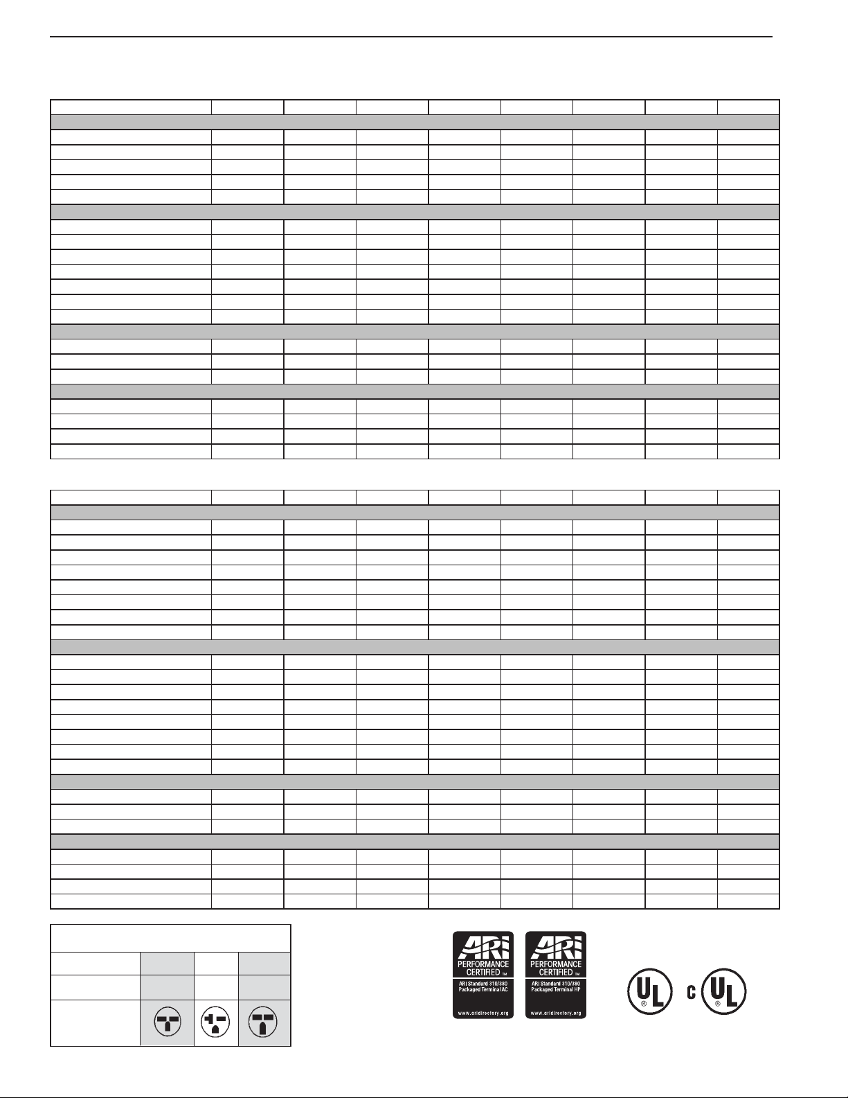
PDE SERIES CHASSIS SPECIFICATIONS
MODEL PDE07K PDE07R PDE09K PDE09R PDE12K PDE12R PDE15K PDE15R
PERFORMANCE DATA:
COOLING BTUh 7500/7300 7500 9000/8800 9000 11500/11300 11500 14000/13800 14000
POWER (WATTS) 647/629 658 789/772 818 1127/1108 1139 1505/1484 1505
EER 11.6 11.4 11.4 11.0 10.2 10.1 9.3 9.3
DEHUMIDIFICATION (pints/hr) 1.7 1.6 3.4 3.3 2.9 2.8 3.8 3.8
SENSIBLE HEAT RATIO 0.77 0.76 0.71 0.79 0.71 0.72 0.68 0.68
ELECTRICAL DATA:
VOLTAGE (1 PHASE, 60 Hz) 230/208 265 230/208 265 230/208 265 230/208 265
VOLT RANGE 253-198 292-239 253-198 292-239 253-198 292-239 253-198 292-239
CURRENT (AMPS) 3.3/3.4 2.9 3.6/3.9 3.3 5.5/5.8 4.6 7.0/7.4 6.4
POWER FACTOR 0.98 0.95 0.97 0.94 0.98 0.97 0.95 0.95
AMPS L.R. 13.0 15.0 19.8 16.8 27.0 23.0 32.0 27.0
AMPS F.L. 2.9 2.6 3.7 3.2 5.0 4.0 6.3 5.6
HORSEPOWER 0.625 0.625 0.75 0.75 1.0 1.0 1.1 1.1
AIRFLOW DATA:
INDOOR CFM, HIGH 220 245 220 210 325 315 310 340
INDOOR CFM, LOW 200 200 200 200 260 260 280 280
VENT CFM 60 60 60 60 70 70 70 70
PHYSICAL DATA:
DIMENSIONS 16x42x13.5 16x42x13.5 16x42x13.5 16x42x13.5 16x42x13.5 16x42x13.5 16x42x13.5 16x42x13.5
NET WEIGHT 105 105 112 112 120 120 125 125
SHIPPING WEIGHT 125 125 132 132 140 140 145 145
R-410A CHARGE (oz) 42 35 36 35 33 35 48 42
PDH SERIES CHASSIS SPECIFICATIONS
MODEL PDH07K PDH07R PDH09K PDH09R PDH12K PDH12R PDH15K PDH15R
PERFORMANCE DATA:
COOLING BTUh 7300/7100 7200 8500/8300 8500 11500/11300 12000 14000/13800 14000
POWER (WATTS) cool 658/640 649 787/769 810 1173/1153 1237 1522/1500 1522
EER 11.1 11.1 10.8 10.5 9.8 9.7 9.2 9.2
REVERSE HEATING BTUh 6400 6300 8000 7700 10500 10500 12800 12800
POWER (WATTS) HEAT 625 615 781 752 1025 1025 1250 1250
COP 3.0 3.0 3.0 3.0 3.0 3.0 3.0 3
DEHUMIDIFICATION (pints/hr) 1.3 1.3 1.9 2.1 2.8 2.9 3.6 3.7
SENSIBLE HEAT RATIO 0.78 0.78 0.73 0.71 0.72 0.72 0.7 0.72
ELECTRICAL DATA:
VOLTAGE (1 PHASE, 60 Hz) 230/208 265 230/208 265 230/208 265 230/208 265
VOLT RANGE 253-198 292-239 253-198 292-239 253-198 292-239 253-198 292-239
CURRENT (AMPS) 3.2/3.3 2.8 3.6/3.9 3.3 5.4/5.7 5.2 6.7/7.3 6.3
REVERSE HEAT. Amps 2.7/2.8 2.6 4.3/4.5 3.0 4.4/4.7 4.4 6.2/6.5 5.6
POWER FACTOR 0.98 0.97 0.97 0.95 0.97 0.97 0.96 0.95
AMPS L.R. 13.0 15.0 19.8 16.8 27.00 23.0 32.0 27.0
AMPS F.L. 2.9 2.6 3.7 3.2 5.0 4.5 6.3 5.6
HORSEPOWER 0.625 0.625 0.75 0.75 1.0 1.0 1.1 1.1
AIRFLOW DATA:
INDOOR CFM, HIGH 210 240 220 210 320 310 315 330
INDOOR CFM, LOW 200 200 200 200 260 260 280 280
VENT CFM 60 60 60 60 70 70 70 70
PHYSICAL DATA:
DIMENSIONS 16x42x13.5 16x42x13.5 16x42x13.5 16x42x13.5 16x42x13.5 16x42x13.5 16x42x13.5 16x42x13.5
NET WEIGHT 105 105 112 112 120 120 125 125
SHIPPING WEIGHT 125 125 132 132 140 140 145 145
R-410A CHARGE (oz) 37 37
37 33 41 40 39 42
250 V Receptacles and Fuse Types
AMPS 15 20 30
HEATER SIZE 0, 2.5 kW 3.4 kW 5.0 kW
RECEPTACLE
4
Page 5
Cooling & Heating Performance
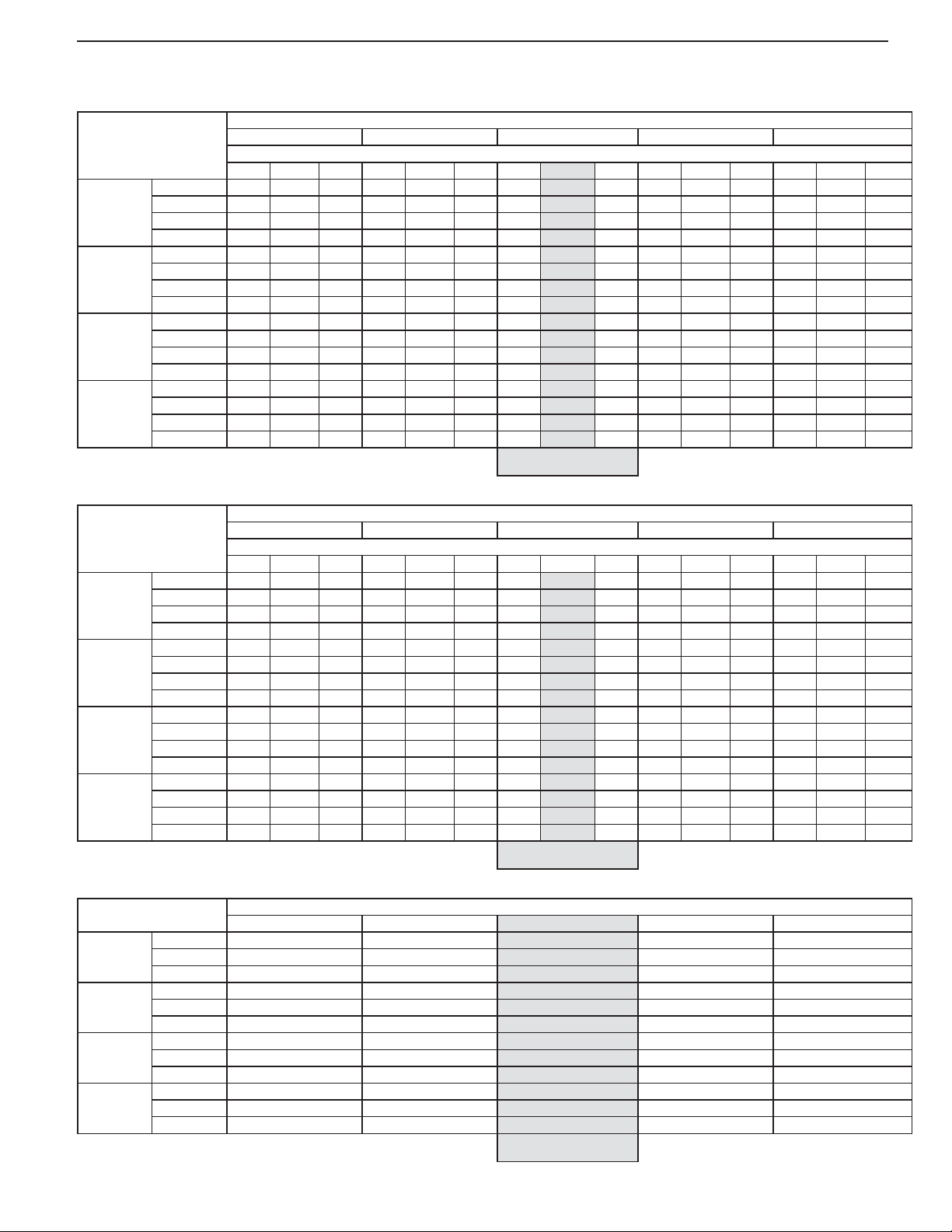
PDE 230V - EXTENDED COOLING PERFORMANCE
75 85 95 105 110
72 67 62 72 67 62 72 67 62 72 67 62 72 67 62
BTUh 8820 8483 7853 8400 7920 7305 8070 7500 6638 7560 6713 5918 6728 5790 5115
PDE07
PDE09
PDE12
PDE15
PDH 230V - EXTENDED COOLING PERFORMANCE
PDH07
PDH09
PDH12
PDH15
EXTENDED HEATING PERFORMANCE
PDH07
PDH09
PDH12
PDH15
WATTS 528 536 542 575 581 588 647 647 647 699 699 701 763 763 766
AMPS 2.7 2.7 2.8 2.9 3.0 3.0 3.3 3.30 3.3 3.6 3.6 3.6 3.9 3.9 3.9
SHR 0.53 0.72 0.96 0.54 0.74 0.98 0.54 0.77 0.99 0.55 0.81 0.99 0.58 0.87 0.99
BTUh 10584 10179 9423 10080 9504 8766 9684 9000 7965 9072 8055 7101 8073 6948 6138
WATTS 644 654 661 701 709 717 789 789 789 853 852 854 930 930 934
AMPS 3.0 3.0 3.0 3.2 3.2 3.2 3.6 3.60 3.6 3.9 3.9 3.9 4.2 4.2 4.2
SHR 0.49 0.66 0.89 0.5 0.69 0.91 0.5 0.71 0.91 0.51 0.75 0.92 0.54 0.8 0.91
BTUh 13524 13007 12041 12880 12144 11201 12374 11500 10178 11592 10293 9074 10316 8878 7843
WATTS 920 934 944 1002 1012 1024 1127 1127 1127 1218 1217 1221 1329 1329 1334
AMPS 4.6 4.6 4.6 4.9 4.9 5.0 5.5 5.50 5.5 5.9 5.9 5.9 6.5 6.5 6.5
SHR 0.49 0.66 0.89 0.5 0.69 0.91 0.5 0.71 0.91 0.51 0.75 0.92 0.54 0.8 0.91
BTUh 16464 15834 14658 15680 14784 13636 15064 14000 12390 14112 12530 11046 12558 10808 9548
WATTS 1228 1248 1261 1338 1351 1368 1505 1505 1505 1627 1625 1630 1774 1774 1782
AMPS 5.8 5.8 5.9 6.2 6.3 6.3 7.0 7.00 7.0 7.5 7.5 7.6 8.2 8.2 8.2
SHR 0.47 0.63 0.85 0.48 0.66 0.87 0.48 0.68 0.87 0.49 0.72 0.88 0.51 0.77 0.87
75 85 95 105 110
72 67 62 72 67 62 72 62 72 67 62 72 67 62
BTUh 8585 8256 7643 8176 7709 7110 7855 7300 6461 7358 6534 5760 6548 5636 4979
WATTS 537 545 551 585 591 598 658 658 658 711 711 713 776 776 779
AMPS 2.6 2.7 2.7 2.9 2.9 2.9 3.2 3.20 3.2 3.4 3.4 3.5 3.8 3.8 3.8
SHR 0.53 0.73 0.98 0.55 0.75 1.00 0.55 0.78 1.00 0.56 0.82 1.01 0.59 0.88 1.00
BTUh 9996 9614 8900 9520 8976 8279 9146 8500 7523 8568 7608 6707 7625 6562 5797
WATTS 642 652 660 700 707 715 787 787
AMPS 3.0 3.0 3.0 3.2 3.2 3.2 3.6 3.60 3.6 3.9 3.9 3.9 4.2 4.2 4.2
SHR 0.5 0.68 0.91 0.51 0.71 0.93 0.51 0.73 0.94 0.53 0.77 0.94 0.55 0.82 0.93
BTUh 13524 13007 12041 12880 12144 11201 12374 11500 10178 11592 10293 9074 10316 8878 7843
WATTS 957 972 983 1043 1053 1066 1173 1173 1173 1268 1267 1270 1383 1383 1389
AMPS 4.5 4.5 4.5 4.8 4.8 4.9 5.4 5.40 5.4 5.8 5.8 5.8 6.3 6.3 6.4
SHR 0.49 0.67 0.9 0.5 0.7 0.92 0.51 0.72 0.92 0.52 0.76 0.93 0.54 0.81 0.92
BTUh 16464 15834 14658 15680 14784 13636 15064 14000 12390 14112 12530 11046 12558 10808 9548
WATTS 1242 1262 1275 1353 1367 1383 1522 1522 1522 1645 1644 1648 1794 1794 1802
AMPS 5.5 5.6 5.6 6.0 6.0 6.0 6.7 6.7 6.7 7.2 7.2 7.2 7.9 7.9 7.9
SHR 0.48 0.65 0.88 0.49 0.68 0.89 0.49 0.70 0.90 0.50 0.74 0.90 0.53 0.79 0.9
37 42 47 52 57
BTUh 5333 5628 6400 7009 7741
WATTS 589 600 625 635 671
AMPS 2.6 2.8 2.75 2.9 3
BTUh 5930 6320 8000 8540 9130
WATTS 701 712 781 786 797
AMPS 3.8 3.8 3.9 3.9 4
BTUh 7582 8372 10500 11067 12006
WATTS 896 931 1025 1055 1089
AMPS 4.2 4.3 4.7 4.9 5.1
BTUh 10134 10442 12800 14003 15341
WATTS 1151 1166 1250 1324 1384
AMPS 5.7 5.8 6.3 6.6 6.9
OUTDOOR DRY BULB TEMP. (DEGREES F AT 40% R.H.)
INDOOR WET BULB TEMP. (DEGREES F AT 80 F D.B.)
RATING POINT
ARI 310/380
OUTDOOR DRY BULB TEMP. (DEGREES F AT 40% R.H.)
INDOOR WET BULB TEMP. (DEGREES F AT 80 F D.B.)
787 851 850 852 928 928 932
RATING POINT
ARI 310/380
OUTDOOR DRY BULB TEMP. (DEGREES F)
RATING POINT
ARI 310/380
5
Page 6

Cooling & Heating Performance
PDE 265V - Extended Cooling Performance
75 85 95 105 110
72 67 62 72 67 62 72 67 62 72 67 62 72 67 62
BTUh 8820 8483 7853 8400 7920 7305 8070 7500 6638 7560 6713 5918 6728 5790 5115
PDE07
PDE09
PDE12
PDE15
PDH 265V - Extended Cooling Performance
WATTS 537 545 551 585 591 598 658 658 658 711 711 713 776 776 779
AMPS 2.4 2.4 2.4 2.6 2.6 2.6 2.9 2.90 2.9 3.1 3.1 3.1 3.4 3.4 3.4
SHR 0.52 0.71 0.95 0.53 0.73 0.97 0.53 0.76 0.98 0.55 0.8 0.98 0.57 0.86 0.97
BTUh 10584 10179 9423 10080 9504 8766 9684 9000 7965 9072 8055 7101 8073 6948 6138
WATTS 667 678 685 727 735 744 818 818 818 884 883 886 964 964 969
AMPS 2.7 2.7 2.8 2.9 3.0 3.0 3.3 3.30 3.3 3.6 3.6 3.6 3.9 3.9 3.9
SHR 0.54 0.74 0.99 0.55 0.76 1.01 0.56 0.79 1.01 0.57 0.83 1.02 0.6 0.89 1.01
BTUh 13524 13007 12041 12880 12144 11201 12374 11500 10178 11592 10293 9074 10316 8878 7843
WATTS 929 944 954 1013 1023 1035 1139 1139 1139 1231 1230 1234 1343 1343 1349
AMPS 3.8 3.8 3.9 4.1 4.1 4.1 4.6 4.60 4.6 4.9 4.9 5.0 5.4 5.4 5.4
SHR 0.49 0.67 0.90 0.50 0.70 0.92 0.51 0.72 0.92 0.52 0.76 0.93 0.54 0.81 0.92
BTUh 16464 15834 14658 15680 14784 13636 15064 14000 12390 14112 12530 11046 12558 10808 9548
WATTS 1228 1248 1261 1338 1351 1368 1505 1505 1505 1627 1625 1630 1774 1774 1782
AMPS 5.3 5.3 5.4 5.7 5.7 5.8 6.4 6.40 6.4 6.9 6.9 6.9 7.5 7.5 7.5
SHR 0.47 0.63 0.85 0.48 0.66 0.87 0.48 0.68 0.87 0.49 0.72 0.88 0.51 0.77 0.87
OUTDOOR DRY BULB TEMP. (DEGREES F AT 40% R.H.)
INDOOR WET BULB TEMP. (DEGREES F AT 80 F D.B.)
RATING POINT
ARI 310/380
75 85 95 105 110
72 67 62 72 67 62 72 67 62 72 67 62 72 67 62
BTUh 8467 8143 7538 8064 7603 7013 7747 7200 6372 7258 6444 5681 6458 5558 4910
PDH07
PDH09
PDH12
PDH15
WATTS 530 538 544 577 583 590 649 649 649 702 701 703 765 765 768
AMPS 2.3 2.3 2.4 2.5 2.5 2.5 2.8 2.80 2.8 3.0 3.0 3.0 3.3 3.3 3.3
SHR 0.53 0.73 0.98 0.55 0.75 1.00 0.55 0.78 1.00 0.56 0.82 1.01 0.59 0.88 1.00
BTUh 9996 9614 8900 9520 8976 8279 9146 8500 7523 8568 7608 6707 7625 6562 5797
WATTS 661 671 679 720 727 736 810 810 810
AMPS 2.7 2.7 2.8 2.9 3.0 3.0 3.3 3.30 3.3 3.6 3.6 3.6 3.9 3.9 3.9
SHR 0.49 0.66 0.89 0.5 0.69 0.91 0.5 0.71 0.91 0.51 0.75 0.92 0.54 0.8 0.91
BTUh 14112 13572 12564 13440 12672 11688 12912 12000 10620 12096 10740 9468 10764 9264 8184
WATTS 1009 1025 1037 1100 1111 1124 1237 1237 1237 1337 1336 1340 1458 1458 1465
AMPS 4.3 4.3 4.4 4.6 4.7 4.7 5.2 5.20 5.2 5.6 5.6 5.6 6.1 6.1 6.1
SHR 0.49 0.67 0.90 0.50 0.70 0.92 0.51 0.72 0.92 0.52 0.76 0.93 0.54 0.81 0.92
BTUh 16464 15834 14658 15680 14784 13636 15064 14000 12390 14112 12530 11046 12558 10808 9548
WATTS 1242 1262 1275 1353 1367 1383 1522 1522 1522 1645 1644 1648 1794 1794 1802
AMPS 5.2 5.2 5.3 5.6 5.6 5.7 6.3 6.3 6.3 6.8 6.8 6.8 7.4 7.4 7.4
SHR 0.49 0.67 0.90 0.50 0.70 0.92 0.51 0.72 0.92 0.52 0.76 0.93 0.54 0.81 0.92
Extended Heating Performance
37 42 47 52 57
BTUh 5250 5540 6300 6900 7620
PDH07
PDH09
PDH12
PDH15
6
WATTS 580 590 615 625 660
AMPS 2.5 2.6 2.6 2.7 2.8
BTUh 5708 6083 7700 8220 8788
WATTS 675 686 752 757 767
AMPS 2.9 2.9 3.0 3.0 3.1
BTUh 7582 8372 10500 11067 12006
WATTS 896 931 1025 1055 1089
AMPS 3.9 4 4.4 4.6 4.8
BTUh 10134 10442 12800 14003 15341
WATTS 1151 1166 1250 1324 1384
AMPS 5.1 5.2 5.6 5.9 6.1
OUTDOOR DRY BULB TEMP. (DEGREES F AT 40% R.H.)
INDOOR WET BULB TEMP. (DEGREES F AT 80 F D.B.)
876 875 877 955 955 959
RATING POINT
ARI 310/380
OUTDOOR DRY BULB TEMP. (DEGREES F)
RATING POINT
ARI 310/380
Page 7

Electric Heat Data
Electric Heat Data
PDE/PDH07K PDE/PDH07R
Heater WATTS 2500/2050 3400/2780 2500 3400
Voltage 230/208 265
Heating BTUh 8500/7000 11600/9500 8500 11600
Heating current (AMPS) 11.4/10.4 15.3/13.9 9.8 13.2
Minimum circuit ampacity 14.1 19.0 12.2 16.4
Brance circuit fuse (AMPS) 15 20 15 20
Electric Heat Data
PDE/PDH09K PDE/PDH09R
Heater WATTS 0 Kw 2500/2050 3400/2780 5000/4090 2500 3400 5000
Voltage 230/208 265
Heating BTUh 0 8500/7000 11600/9500 17000/13900 8500 11600 17000
Heating current (AMPS) 0 11.4/10.4 15.3/13.9 22.3/20.3 9.8 13.2 19.5
Minimum circuit ampacity 5.2 14.1 19 27.8 12.2 16.4 24.2
Brance circuit fuse (AMPS) 15 15 20 30 15 20 30
Electric Heat Data
PDE/PDH12K PDE/PDH12R
Heater WATTS 0 Kw 2500/2050 3400/2780 5000/4090 2500 3400 5000
Voltage 230/208 265
Heating BTUh 0 8500/7000 11600/9500 17000/13900 8500 11600 17000
Heating current (AMPS) 0 11.4/10.4 15.3/13.9 22.3/20.3 9.8 13.2 19.5
Minimum circuit ampacity 7.9 14.1 19 27.8 12.2 16.4 24.2
Brance circuit fuse (AMPS) 15 15 20 30 15 20 30
Electric Heat Data
PDE/PDH15K PDE/PDH15R
Heater WATTS 0 Kw 2500/2050 3400/2780 5000/4090 2500 3400 5000
Voltage 230/208 265
Heating BTUh 0 8500/7000 11600/9500 17000/13900 8500 11600 17000
Heating current (AMPS) 0 11.4/10.4 15.3/13.9 22.3/20.3 9.8 13.2 19.5
Minimum circuit ampacity 8.5 14.1 19 27.8 12.2 16.4 24.2
Brance circuit fuse (AMPS) 15 15 20 30 15 20 30
Due to continuing research in new energy-saving technology, specif ications
are subject to change without notice.
7
Page 8

Model Identication / Components / Dimensions
PTAC/PTHP Model Identication Guide
PD H 07 K 3 S E A
Series
PD = Friedrich Digital PTAC
System
X = Accessory
E = Cooling with or without electric heat
H = Heat Pump with Auxiliary Heat
NOMINAL CAPACITY
07 = 7,000 Btuh
09 = 9,000 Btuh
VO LTAG E
K = 230/208V - 1 Ph. - 60 Hz.
R = 265V - 1 Ph. - 60 Hz.
12 = 12,000 Btuh
15 = 15,000 Btuh
Typical Unit Components and Dimensions
Wall Sleeve
Filters
Engineering Digit
Design Series
Note: All PTAC models with a C design series
or later come standard with Diamonblue
seacoast protection and digital controls.
Chassis
S = Standard
Nominal Heater Size (@ 230V or 265V)
0 = No Heater (only on PDE09 K, PDE12K AND PDE15K)
2 = 2.5 KW * 3 = 3.4 KW 5 = 5.0 KW**
* 2.5 kw only available on 7000, 9 000, and 12000 BTU models
** 5.0 kw only available on 12000 and 15000 BTU models
Outdoor Louver
PDXWS Wall Sleeve Dimensions:
16" H x 42" W x 13 ¾" D
Return Air Grille
Front Cover Dimensions:
16" H x 42" W x 7 ½" D
Cut-Out Dimensions:
16 ¼" x 42 ¼"
Chassis
Front Cover
8
Page 9

Cooling Only, Electric Heat, Heat Pump
All models use
environmentally
friendly R-410A
refrigerant.
R-410A
PURCHASER P.O. # DATE
PROJECT LOCATION
ENGINEER ARCHITECT
SUBMITTED BY FOR APPROVAL FOR REFERENCE
ITEM PLAN DESIGNATION QUANTITY COOLING BTU/H VOLTAGE FRIEDRICH MODEL
Accessories
PTAC
PDXWS Wall Sleeve Qty
PXWE Deep Wall Extension Qty
PXGA Standard Outdoor Louver Qty
PXAA Architectural Louver, clear Qty
PXBG Architectural Louver, beige Qty
PXSC Architectural Louver, color matched Qty
RT4 Digital Thermostat Qty
RT5 Digital Thermostat Qty
PDXRT Remote Thermostat Escutcheon Kit Qty
Features
• Electronictemperaturelimiting
• Constantcomfortroom
monitoring
• Deskcontrolready
• Auxiliaryfanready
• Remotethermostatoperation
• “InstantHeat”heatpumpmode
• Remotecontroloperation
• Evenheatmonitoring
• Randomcompressorrestart
• Highefficiency
• Roomfreezeprotection
• Filteredfreshairintake
• Fancyclecontrol
• Electronicdefrostcontrol
• Shipsindividuallypalletized
• Singlemotordesign
• Serviceerrorcodestorage
• Top-mountedantimicrobialair
filters
• Emergencyheatoverride
• Durabledesign
• Powdercoatpaintprocess
• Aluminumendplates
• Indoorcoilfrostsensor
• DiamonblueTechnology
advancedcorrosion
protection
PDXRC Remote Control Qty
PXDR10 Condensate Drain Kit (pkg/10) Qty
PXSB Sub Base Qty
PXSE T-Series Sleeve Adapter Qty
PXCJ Conduit Kit w/Junction Box Qty
PDXDA Lateral Duct Adapter Qty
PDXDE Lateral Duct Extension Qty
PXPC15/20/30 Sub Base Power Cord Kit Qty
PTAC_SUBMITTAL_10
Standa rd on all model S.
This adv anced corro sion protec tion treatm ent protec ts the
outdoo r coil against d eteriora tion and exte nds the life of
the unit e specially in h arsh coasta l environmen ts.
optional
remote
9
Page 10

Installation
Typical Wall Sleeve Installation (PDXWS)
Lintel Used To Support
Masonry Walls
10" Maximum
42 ¼"
Minimum
Wall Opening
16 ¼"
Electrical
Receptacle
50"Max
Insulation
Electrical
Receptacle
Main Studs
Jack Stud
13 ¾"
LINTEL
Mounting
Screw Holes
No holes are permitted in the top or bottom
of the sleeve. (Exception: PXDR10 Drain
Kit)
Extended Wall Sleeve Installation and Sealant Locations (PXWE)
Wall Sleeve Extension, 42" x 16" Frame,
20-gauge minimum, painted or aluminum
Smooth side of clip on Room side
Note the use of a lintel under the rst course
of bricks above the wall sleeve. Do not use
the wall sleeve as a lintel. The mounting
screw holes shown are to be made by the
installer.
Note: All 230/208V units are manufactured
with a 60" power cord. The receptacle locations above must be followed to ensure
proper connections.
10
Width of Wall
Wall Sleeve
Condensate Drip
Panel (Field Supplied)
Outside
Edge
Bafes
2
9 1/
Condensate
Air
Four
Notches
Sealant inside (4) bottom
corners
IMPORTANT NOTE:
The silicone bead MUST
extend 3" up the side
of the two anges to
prevent condensate from
leaking.
Page 11

Accessory Installation
Internal Drain Kit Location and Installation (PXDR10)
Wall Sleeve
Bottom
Foam Gasket
Mounting Plate
Tube
Screw
Screw
PRIMARY AREA:
Condensation from the
chassis collects in the sleeve
in this area.
The Primar y Area is the
preferred installation location.
PXDR10 DRAIN KIT
1/2" O.D. Tube
Gasket
Mounting Plate
External Drain
When using an external drain system, the
condensate is removed through either of two
drain holes on the back of the wall sleeve.
Select the drain hole which best meets your
drainage situation and install the drain kit. Seal
off the other with a cover plate.
Place the drain tube through the gasket and
the mounting plate with the ange toward the
wall sleeve.
Attach the drain tube assembly to one of the
two drain holes at the rear of the wall sleeve.
The large ange on the mounting plate is
positioned at the bottom of the sleeve facing
toward the sleeve. When the drain tube is
positioned at the desired angle, tighten the
screws.
Back of
wall sleeve
Foam Gasket
Overow Slots
1/2" O.D. Tube
Mounting Plate
Foam Gasket
Cover Plate
Architectural Louver Installation (PXAA)
CAUTION
Bodily injury can be caused by louvers
falling from a building during installation. It is
recommended that a safety line be attached
to the louver and an anchor point inside the
building during installation.
INSTA LL ATION
1. Screw a threaded metal stud into each of the
holes at the four corners of the louver.
2. From inside the building, grasp the louver
at the vertical supports and maneuver the
louver through the wall sleeve. Pull towards
you until the threaded studs are inserted into
the four holes of the wall sleeve.
3. While holding the louver with one hand, start
washers and nuts on each of the four studs.
Tighten the nuts securely.
11
Page 12

HVAC Engineering Specications
Digital Packaged Terminal Air Conditioners & Heat Pumps
Cooling: 7,100 – 14,000 Btuh
Heating: 7,000 – 13,900 Btuh (Heat Pump)
8,500 – 17,000 Btuh (Electric Heat)
Friedrich Models: PDE – Cooling with or without electric heat
PDH – Heat Pump with electric heat
All units shall be factor y assembled, piped, wired and fully charged
with R-410A. All units shall be cer tied in accordance with ARI
Standard 310 for air conditioners and ARI standard 380 for heat
pumps. Units shall be UL listed and carry a UL label. All units shall
be factory run-tested to check operation and be manufactured by
Friedrich or equivalent.
The basic unit shall not exceed 16" high x 42" wide. Overall depth
of the unit from the rear of the Friedrich wall sleeve to the front of
the decorative front cover shall not exceed 21 ¼". The unit shall be
de si gned so th at ro om int ru sion may be as little as 7 ½". Ins talla tions
in walls deeper than 13 ¼" may be accomplished with the use of a
wa ll sle eve exte nsion (PX WE ). Un it sh all d raw i n ambi ent a ir th rough
both sides of an outdoor architectural louver or grille measuring 42"
wide x 16" high and shall exhaust air out middle portion of the louver.
The architectural louver and wall sleeve shall be designed so that the
louver may be installed from the inside of the building.
REFRIGERATION SYSTEM – The refrigeration system shall be
hermetically sealed and consist of a rotary compressor that is externally mounted on vibration isolators no smaller than 1 ¾" dia. x 1 ½"
high; condenser and evaporator coils constructed of copper tubes
and alum in um plate ns; and capillaries as expansion devices. Unit
shall have a fan slinger ring to increase efciency and condensate
disposal and have a drain pan capable of retaining 1 ½ gallons of
condensate. A tertiary condensate removal system shall also be
incorporated for back up and shall overow through the wall sleeve
and to the outside of the building as a safeguard against damage
to the interior room.
AIR HANDLING SECTION – The evaporator and condenser
fans shall be directly driven by a single, totally enclosed, ball
bearing, permanently lubricated split capacitor, “clam-shell" style
fan motor. Airow shall be directed into the room by a single,
injection molded, high-impact polystyrene discharge grille. The
grille shall have openings no larger than
prevent personal injury or damage to the PTAC unit, and will
be reversible to allow air to be directed upward or outward as
determined by the installer.
The chas si s sh all h ave a bui lt-in d ampe r capa ble of prov idin g at l east
60 CFM of fresh air into the conditioned area. A ne mesh screen
shall lter the inc oming fresh air. There must be a provision for lock-
ing the damper closed to ensure a proper seal.
CONTROLS – Covered controls shall be accessible in a compartment at least 9" wide with the controls no deeper than 1 ¼" in the
opening to facilitate easy operation of the unit.
3
/8" high x 3" wide to
The unit must have the following energy saving and convenience
features built-in:
• Quiet start/stop fan delay
• Room freeze protection
• Random compressor restart
• Electronic temperature limiting
• Wireless remote control ready
• Internal diagnostics
The PTAC must also offer the ability to be controlled by a remote
wall-mounted thermostat without additional accessories. Low voltage inputs will include: C (common), R (24V power), Y (cooling), GL
(fan low), GH (fan high), W (heat) and B (reversing valve on PDH
heat pumps only).
The PTAC unit must also be able to be controlled by an optional hand
held wireless remote control. The remote control shall be capable
of all basic control functions of the PTAC including: power on/off,
cooling, heating, fan speed and temperature setting.
Other controls accessible without removal of the chassis shall include
fan cycle switch, fresh air vent control and emergency heat override
switch (heat pump only).
GENERAL CONSTRUCTION – T he wa ll sle eve shall be cons tr ucte d
of 18-gauge Galvanized zinc-coated steel. It shall be prepared by
a process where it is zinc phosphate pretreated and sealed with a
chr oma te r ins e, t hen pow der coated w ith a po lye ste r n ish and oven
cured for durability. The sleeve shall be shipped with a protective
weatherboard and a structural center support, and be insulated for
sound absorption and thermal efciency. The grille or louver shall be
shipped separately and made from stamped or extruded anodized
aluminum. All louvers shall be in the horizontal plane.
The front panel shall lock to the chassis by means of two factory-
supplied thumbscrews to prevent tampering. The front panel will
feature a contoured discharge with no sharp corners. The air lters
shall be reusable and be accessible without removal of the front
cover. The lters will feature an antimicrobial coating to prevent
mold and bacterial growth.
All 265V units shall possess an integral, over-current time-delay
protective device.
CORROSION PROTECTION – The unit shall have a corrosionresistant fan, fan shroud and drain pan for corrosion protection and
to prevent rust on the side of the building below the outdoor louver.
The unit shall feature corrosion resistant materials and nishes to help
prevent deterioration. The outdoor coil shall have Diamonblue cor-
rosion protection consisting of hydrophilic coated ns to prolong the
life of the coil in all applications including seacoast environments.
WARRANTY – The warranty is one year on all parts and 5 years on
the sealed system including compressor, indoor and outdoor coils
and refrigerant tubing.
• Service code storage
• Constant comfort room monitoring
• Instant heat heat pump mode
• Desk control terminals
• Indoor coil frost sensor
• Auxiliary fan control
The unit controls shall feature an LED readout that can display
either room temperature or setpoint temperature. The unit shall
receive input from the SMART CENTER
push buttons labeled: ‘Cool’, ‘Heat’, ‘High Fan’, ‘Low Fan’,
and ‘Power’. When 'Off', the unit may be put directly into cooling
or heating mode by pressing the ‘Cool’ or ‘Heat’ button.
®
control panel through
’, ‘ ’
12
Page 13

Accessories
New Construction Accessories
WALL SLEEVE Galvanized zinc coated steel is prepared in an 11-step
PDXWS
process, then powder coated with a polyester nish and cured in an oven
for exceptional durability. The wall sleeve is insulated for sound absorption
and thermal efciency. 16" High x 42" Wide x 13 ¾" Deep.
PXGA
PXAA
PXBG
PXSC
PXDR10
PXWE
PXSB
GRILLE Standard, stamped aluminium, anodized to resist chalking and
oxidation.
ARCHITECTURAL GRILLES Consist of heavy-gauge 6063-T5 aluminum
alloy:
PXAA– Clear, extruded aluminum
PXBG– Beige acrylic enamel
PXSC– Also available in custom colors.
CONDENSATE DRAIN KIT Attaches to the bottom of the wall sleeve for
internal draining of condensate or to the rear wall sleeve ange for external
draining. Recommended on all units to remove excess condensate. Packaged in quantities of ten.
DEEP WALL SLEEVE EXTENSION A four-inch deep anodized aluminium
extension that attaches to the outside of the wall sleeve when the wall is
greater than 11 inches thick (9 ½" when a subbase is used, 10 inches when
a lateral duct is used). Up to three extensions my be used together.
DECORATIVE SUBBASE Provides unit support for walls less than six
inches thick. Includes leveling legs, side ller panels and mounting brackets
for electrical accessories. Accepts circuit breaker, power disconnect switch,
or conduit kit.
PXAA
RT4
RT5
PDXRT
PDXRC
DIGITAL REMOTE WALL THERMOSTAT Single stage thermostat used on
PTAC units. Hard wired with single speed fan. Direct replacement for RT2.
DIGITAL REMOTE WALL THERMOSTAT Sin gle s tage t hermos tat fe atur es
high/low fan speed switch. Thermostat is hard wired and can be battery
powered or unit powered. Features backlit display and multiple conguration
modes. For use on PD-series Friedrich PTACs and Vert-I-Paks.
REMOTE THERMOSTAT ESCUTCHEON KIT This kit co nt ains ten e scutc heons that can be placed over the factory control buttons when a remote wall
mounted thermostat is used. The escutcheon directs the guest to the wall
thermostat for operation and retains the LED window to display error codes
and diagnostic information.
WIRELESS HAND HELD REMOTE CONTROL This kit contains one
remote control that can be used to operate any 2008 “D” model PTAC or
newer. The remote control can be used to control all user functions of the
PTAC unit including: power on/off, cool/heat/fan mode selection, fan speed
and temperature setpoint. Each kit contains one remote control and a ller
panel for use when the control door is removed.
13
Page 14

Additional Accessories
SLEEVE EXTENSION RETROFIT KIT Galvanized zinc coated
PXSE
PDXDA
steel, 2.4" sleeve extension attached to the room side of the sleeve
to allow for the installation of a PD-Series Friedrich PTAC in a TSeries sleeve.
LATERAL DUCT ADAPTER Attaches to the PTAC/PTHP unit and
provides a transition to direct up to 35% of the total CFM to a secondary
room, either left or right of the unit. Kit includes duct plenum with
discharge grille and internal bafe, adapter and end cap.
PDXDE
PXCJ
PXPC
15/20/30
LATERAL DUCT EXTENSION A thre e- foot insu lat ed pl enum t hat
attaches to the left or right side of the duct adapter. The extension
can be cut to length by the inst aller. Maximum allowable straight
extension is 15 feet.
CONDUIT KIT WITH JUNCTION BOX Hard wire conduit kit with
junction box for 208/230V and 265V units (subbase not required).
Kit includes a means of quick disconnect for easy removal of the
chassis. *Required for 265V installations.
POWER CORD RETROFIT Replaces LCDI power cord on 230V
models when unit is used with a subbase. PXPC15 is used with
15 amp 2.5 kW units. PXPC20 is used with 20 amp 3.4 kW units.
PXPC30 is used with 30 amp 5.0 kW units.
PDXDA
PXPC30
14
Page 15

15
Page 16

Friedrich Air Conditioning Company
P.O. Box 1540
San Antonio, TX 78295
210.357.4400
www.friedrich.com
PD-SERIES
PACKAGED TERMINAL AIR CONDITIONERS
LIMITED WARRANTY
SAVE THIS CERTIFICATE. It gives you specic rights. You may also have other rights which may vary from state to state and province to province.
In the event that your unit needs servicing, contact your nearest authorized service center. If you do not know the nearest service center, ask the company
that installed your unit or contact us - see address and telephone number above. To obtain service and/or warranty parts replacement, you must notify an
authorized FRIEDRICH Air Conditioning Co. service center, distributor, dealer, or contractor of any defect within the applicable warranty period.
When requesting service: please have the model and serial number from your unit readily available.
Unless specied otherwise herein, the following applies:
FRIEDRICH PACKAGED TERMINAL AIR CONDITIONERS AND HEAT PUMPS
LIMITED WARRANTY - FIRST YEAR (Twelve (12) months from the date of installation). Any part found to be defective in the material or workmanship
will be repaired or replaced free of charge by our authorized service center during the normal working hours; and
LIMITED WARRANTY - SECOND THROUGH FIFTH YEAR (Sixty (60) months from the date of installation). ON THE SEALED REFRIGERATION
SYSTEM. Any part of the sealed refrigeration system that is defective in material or workmanship will be repaired or replaced free of charge (excluding
freight charges) by our authorized service center during normal working hours. The sealed refrigeration system consists of the compressor, metering device,
evaporator, condenser, reversing valve, check valve, and the interconnecting tubing.
These warranties apply only while the unit remains at the original site and only to units installed inside the continental United States, Alaska,
Hawaii, Puerto Rico, Mexico and Canada. The warranty applies only if the unit is installed and operated in accordance with the printed instructions
and in compliance with applicable local installation and building codes and good trade practices. For international warranty information, contact
the Friedrich Air Conditioning Company - International Division.
Any defective part to be replaced must be made available to FRIEDRICH in exchange for the replacement part. Reasonable proof must be presented to
establish the date of install, otherwise the beginning date of this certicate will be considered to be our shipment date plus sixty days. Replacement parts can
be new or remanufactured. Replacement parts and labor are only warranted for any unused portion of the unit’s warranty.
We will not be responsible for and the user will pay for:
1. Service calls to:
A) Instruct on unit operation. B) Replace house fuses or correct house wiring. C) Clean or replace air lters. D) Remove the unit from its installed
location when not accessible for service required. E) Correct improper installations.
2. Parts or labor provided by anyone other than an authorized service center.
3. Damage caused by:
A) Accident, abuse, negligence, misuse, riot, re, ood, or acts of God. B) Operating the unit where there is a corrosive atmosphere containing
chlorine, uorine, or any damaging chemicals (other than in a normal residential environment). C) Unauthorized alteration or repair of the unit, which
in turn affects its stability or performance. D) Failing to provide proper maintenance and service. E) Using an incorrect power source. F) Faulty
installation or application of the unit.
We shall not be liable for any incidental, consequential, or special damages or expenses in connection with any use or failure of this unit. We have
not made and do not make any representation or warranty of tness for a particular use or purpose and there is no implied condition of tness for
a particular use or purpose. We make no expressed warranties except as stated in this certicate. No one is authorized to change this certicate
or to create for us any other obligation or liability in connection with this unit. Any implied warranties shall last for one year after the original
purchase date. Some states and provinces do not allow limitations on how long an implied warranty or condition lasts, so the above limitations or exclusions
may not apply to you. The provisions of this warranty are in addition to and not a modication of or subtraction from the statutory warranties and other rights
and remedies provided by law.
Performance of Friedrich’s Warranty obligation is limited to one of the following methods:
1. Repair of the unit
2. A refund to the customer for the prorated value of the unit based upon the remaining warranty period of the unit.
The method of fulllment of the warranty obligation is at the sole discretion of Friedrich Air Conditioning.
Providing a replacement unit of equal value3.
In case of any questions regarding the provisions of this warranty, the English version will govern.
PTAC-PP-10
(10-09)
 Loading...