

Page 1
INCREDIBLE!
AMERICA'S BEST AIR CONDITIONER
12.2 EER
PTAC
PRODUCT PROFILE
PACKAGED TERMINAL AIR CONDITIONERS AND HEAT PUMPS
®
WallMaster
7,000 / 9,000 / 12,000 / 15,000 Btu/h
The All-new Friedrich
WallMaster
®
is a perfect fit
for:
New construction in hotels/
motels, medical facilities, assisted
living centers, apartments/condos,
office suites, dormitories and
remodels.
The New WallMaster
into existing 16" x 42" sleeves
more easily than other
manufacturer's PTACs.
®
retrofits
Standard Features
! Ultrahigh efficiency. Up to 12.2 EER.
! Unique component mounting and isolation
provide ultraquiet operation and vibration
dampening.
! Large well spaced control panel with
universal markings and non-removable
controls
! Attractive front cover and tamper resistant
contoured discharge grille blend with any
decor.
! Quiet and efficient rotary compressor
mounted on vibration isolators, with internal
high temperature overload protection.
! Built-in damper allows up to 70 CFM of
fresh air.
! Convenient top-mounted return air filters.
! Available in heat pump or electric heat.
! Front cover fastens to chassis with
thumbscrews hidden from user.
! Emergency heat compressor override
switch on all heat pumps.
! Single, totally enclosed "clam shell" motor
design protects against premature failure.
! Optional seacoast protection for harsh
coastal environments.
! Complete line of accessories.
! Remote thermostat control units are
available.
! Units are rated in accordance with ARI
Standard 310/380.
! Manufactured in the U.S.A.
Page 2
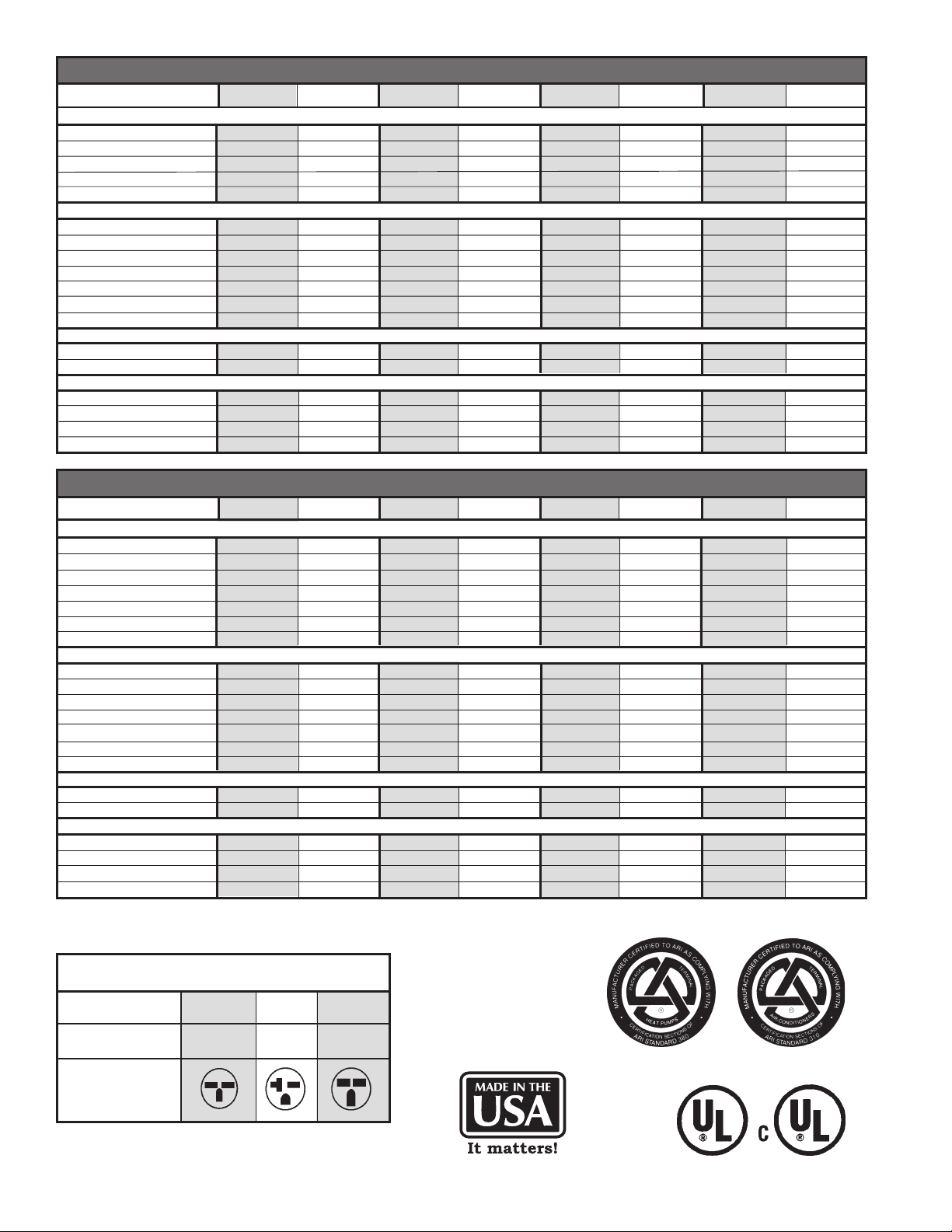
PE Series Chassis Specifications
MODELS: PE07K PE07R PE09K PE09R PE12K PE12R PE15K PE15R
PERFORMANCE DATA:
Cooling Btuh.
Cooling Power (W)
EER
Dehumidification (Pts/h)
Sensible Heat Ratio
ELECTRICAL DATA:
Voltage (1 Ph, 60Hz)
Voltage Range
Current (Amps) (A)
Power Factor
Amps L.R
Amps F.L.
Horsepower
AIRFLOW DATA:
Indoor CFM
Vent CFM
PHYSICAL DATA:
Dimensions (HxWxD) (In.)
Net Weight
Shipping Weight
R-22 Charge
7500/7300
615/598
12.2
2.1
0.76
230/208
253-198
3.0
0.9
18
3
1/15
250
60
16x42x13.75
105
123
27
7500
615
12.2
2.1
0.76
265
292-239
3.0
0.9
18
3
1/15
250
60
16x42x13.75
105
123
27
9200/9000
814/796
11.3
2.7
0.75
230/208
253-198
3.9
0.9
22.2
3.9
1/12
300
60
16x42x13.75
112
130
32
9200
814
11.3
2.7
0.75
265
292-239
3.9
0.9
22.2
3.9
1/12
300
60
16x42x13.75
112
130
32
12000/11800
1091/1073
11.0
3.8
0.72
230/208
253-198
5.1
0.9
26.3
5.1
1/10
325
70
16x42x13.75
120
138
31
12000
1091
11.0
3.8
0.72
265
292-239
5.1
0.9
26.3
5.1
1/10
325
70
16x42x13.75
120
138
31
15000/14800
1579/1578
9.5
5.5
0.72
230/208
253-198
6.6
0.9
38
6.8
1/10
350
70
16x42x13.75
125
143
34
15000
1579
9.5
5.5
0.72
265
292-239
6.6
0.9
38
6.8
1/10
350
70
16x42x13.75
125
143
34
PH Series Chassis Specifications
MODELS: PH07K PH07R PH09K PH09R PH12K PH12R PH15K PH15R
PERFORMANCE DATA:
Cooling Btuh.
Cooling Power (W)
EER
Heating Btuh
COP
Dehumidification (Pts/h)
Sensible Heat Ratio
ELECTRICAL DATA:
Voltage (1 Ph, 60Hz)
Voltage Range
Current (Amps) (A)
Power Factor
Amps L.R
Amps F.L.
Horsepower
AIRFLOW DATA:
Indoor CFM
Vent CFM
PHYSICAL DATA:
Dimensions (HxWxD)(In.)
Net Weight
Shipping Weight
R-22 Charge
7200/7000
595/579
12.1
6400/6200
3.3
2.1
0.76
230/208
253-198
3.0
0.9
18
3
1/15
250
60
16x42x13.75
105
123
27
7200
595
12.1
6400
3.3
2.1
0.76
265
292-239
3.0
0.9
18
3
1/15
250
60
16x42x13.75
105
123
27
9100/8900
805/788
11.3
8100/7900
3.2
2.7
0.75
230/208
253-198
3.9
0.9
22.2
3.9
1/12
300
60
16x42x13.75
112
130
30
9100
805
11.3
8100
3.2
2.7
0.75
265
292-239
3.9
0.9
22.2
3.9
1/12
300
60
16x42x13.75
112
130
30
12000/11800
1121/1103
10.7
10800/10600
3.1
3.8
0.72
230/208
253-198
5.1
0.9
26.3
5.1
1/10
325
70
16x42x13.75
120
138
28
12000
1121
10.7
10800
3.1
3.8
0.72
265
292-239
5.1
0.9
26.3
5.1
1/10
325
70
16x42x13.75
120
138
28
14700/14500
1581/1559
9.3
13500/13300
2.8
5.5
0.72
230/208
253-198
6.6
0.9
38
6.8
1/10
350
70
16x42x13.75
125
143
41
14700
1581
9.3
13500
2.8
5.5
0.72
265
292-239
6.6
0.9
38
6.8
1/10
350
70
16x42x13.75
125
143
41
250 V Receptacles and Fuse Types
AMPS 15 20 30
HEATER SIZE 0, 2.5 kW 3.4 kW 5.0 kW
RECEPTACLE
2
Page 3
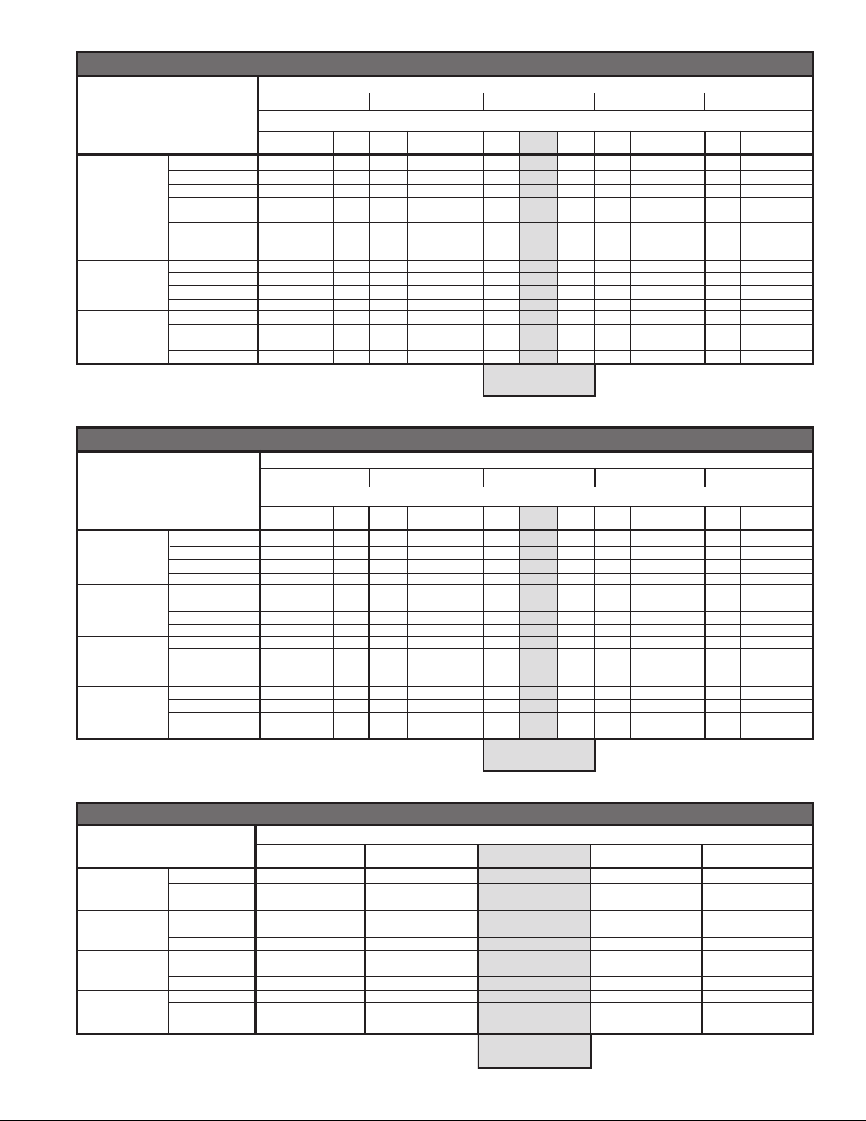
Extended Cooling Performance, PE07/09/12/15
Outdoor Dry Bulb Temp. (°F at 40% R.H.)
75 85 95 105 115
Indoor Wet Bulb Temp. (
72 67 62 72 67 62 72 67 62 72 67 62 72 67 62
PE07
PE09
PE12
PE15
Btuh
Watts
Amps
SHR
Btuh
Watts
Amps
SHR
Btuh
Watts
Amps
SHR
Btuh
Watts
Amps
SHR
8820 8483 7853 8400 7920 7305 8070 7500 6638 7560 6713 5918 6728 5790 5115
502 510 515 547 552 559 615 615 615 665 664 666 725 725 728
2.5 2.5 2.5 2.7 2.7 2.7 3 3.00 3 3.2 3.2 3.2 3.5 3.5 3.5
0.52 0.71 0.95 0.53 0.73 0.97 0.53 0.76 0.98 0.55 0.8 0.98 0.57 0.86 0.97
10819 10405 9632 10304 9715 8961 9899 9200 8142 9274 8234 7259 8252 7102 6274
664 675 682 724 731 740 814 814 814 880 879 882 960 960 964
3.2 3.2 3.3 3.5 3.5 3.5 3.9 3.90 3.9 4.2 4.2 4.2 4.6 4.6 4.6
0.51 0.70 0.94 0.52 0.72 0.96 0.53 0.75 0.96 0.54 0.79 0.97 0.57 0.84 0.96
14112 13572 12564 13440 12672 11688 12912 12000 10620 12096 10740 9468 10764 9264 8184
915 929 939 997 1007 1019 1121 1091 1121 1212 1211 1214 1322 1322 1327
4.2 4.2 4.3 4.5 4.6 4.6 5.1 5.10 5.1 5.5 5.5 5.5 6 6 6
0.49 0.67 0.9 0.5 0.7 0.92 0.51 0.72 0.92 0.52 0.76 0.93 0.54 0.81 0.92
17640 16965 15705 16800 15840 14610 16140 15000 13275 15120 13425 11835 13455 11580 10230
1288 1309 1323 1404 1418 1435 1579 1579 1579 1707 1705 1710 1862 1862 1870
5.5 5.5 5.6 5.9 5.9 5.9 6.6 6.60 6.6 7.1 7.1 7.1 7.7 7.7 7.8
0.51 0.70 0.94 0.52 0.72 0.96 0.53 0.72 0.96 0.54 0.79 0.97 0.57 0.84 0.96
Extended Cooling Performance, PH07/09/12/15
Outdoor Dry Bulb Temp. (°F at 40% R.H.)
75 85 95 105 115
Indoor Wet Bulb Temp. (°F at 80°F D.B.)
72 67 62 72 67 62 72 67 62 72 67 62 72 67 62
PH07
PH09
PH12
PH15
Btuh
Watts
Amps
SHR
Btuh
Watts
Amps
SHR
Btuh
Watts
Amps
SHR
Btuh
Watts
Amps
SHR
8820 8483 7853 8400 7920 7305 8070 7200 6638 7560 6713 5918 6728 5790 5115
502 510 515 547 552 559 615 595 615 665 664 666 725 725 728
2.5 2.5 2.5 2.7 2.7 2.7 3 3.00 3 3.2 3.2 3.2 3.5 3.5 3.5
0.52 0.71 0.95 0.53 0.73 0.97 0.53 0.76 0.98 0.55 0.8 0.98 0.57 0.86 0.97
10819 10405 9632 10304 9715 8961 9899 9100 8142 9274 8234 7259 8252 7102 6274
657 667 675 716 723 732 805 805 805 870 869 872 949 949 953
3.2 3.2 3.3 3.5 3.5 3.5 3.9 3.90 3.9 4.2 4.2 4.2 4.6 4.6 4.6
0.51 0.7 0.94 0.52 0.72 0.96 0.53 0.75 0.96 0.54 0.79 0.97 0.57 0.84 0.96
14112 13572 12564 13440 12672 11688 12912 12000 10620 12096 10740 9468 10764 9264 8184
915 929 939 997 1007 1019 1121 1121 1121 1212 1211 1214 1322 1322 1327
4.2 4.2 4.3 4.5 4.6 4.6 5.1 5.10 5.1 5.5 5.5 5.5 6 6 6
0.49 0.67 0.9 0.5 0.7 0.92 0.51 0.72 0.92 0.52 0.76 0.93 0.54 0.81 0.92
17640 16965 15705 16800 15840 14610 16140 14700 13275 15120 13425 11835 13455 11580 10230
1288 1309 1323 1404 1418 1435 1579 1581 1579 1707 1705 1710 1862 1862 1870
5.5 5.5 5.6 5.9 5.9 5.9 6.6 6.6 6.6 7.1 7.1 7.1 7.7 7.7 7.8
0.51 0.70 0.94 0.52 0.72 0.96 0.53 0.72 0.96 0.54 0.79 0.97 0.57 0.84 0.96
°F at 80°F D.B.)
RATING POINT
ARI 310/380
RATING POINT
ARI 310/380
Extended Heating Performance
37 42 47 52 57
PH07
PH09
PH12
PH15
Btuh
Watts
Amps
Btuh
Watts
Amps
Btuh
Watts
Amps
Btuh
Watts
Amps
5366 5663 6400 7053 7789
536 545 568 577 610
2.5 2.6 2.6 2.7 2.8
6005 6399 8100 8647 9245
666 676 742 747 757
3.1 3.1 3.2 3.2 3.3
7799 8611 10800 11383 12349
893 927 1021 1051 1085
3.8 3.9 4.3 4.5 4.7
10688 11013 13500 14769 16180
1301 1318 1413 1497 1564
5.3 5.4 5.8 6.1 6.3
Outdoor Dry Bulb Temp. (°F)
RATING POINT
ARI 310/380
3
Page 4
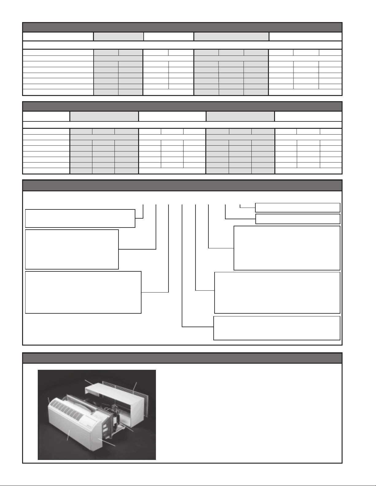
Electric Heat Data, PE/PH 07/09K/R
MODELS: PE/PH07K PE/PH07R PE/PH09K PE/PH09R
PERFORMANCE DATA:
Heater Watts
Voltage
Heating Btuh
Heating Power (Watts)
Heating Current (Amps)
Minimum Circuit Ampacity
Branch Circuit Fuse (Amps)
Nema Plug Face
2500/2050
8500/7000
2600/2150
11.4/10.4
14.1
15
6-15
3400/2780
230/208 265
11600/9500
3500/2880
15.3/13.9
19
20
6-20
2500
8500
2590
9.8
12.2
15
N/A
3400
11600
3490
13.2
16.4
20
2500/2050
8500/7000
2600/2150
11.4/10.4
14.1
15
6-15
3400/2780
230/208
11600/9500
3500/2880
15.3/13.9
19
20
6-20
5000/4090
17000/13900
5210/4300
22.3/20.3
27.8
30
6-30
2500
8500
2590
9.8
12.2
15
3400
265
11600
3490
13.2
16.4
20
N/A
Electric Heat Data, PE/PH 12/15K/R
MODELS: PE/PH12K PE/PH12R PE/PH15K PE/PH15R
ELECTRIC HEAT DATA:
Heating Current (Amps)
Minimum Circuit Ampacity
Branch Circuit Fuse (Amps)
WallMaster
Heater Watts
Voltage
Heating Btuh
Heating Power (Watts)
Nema Plug Face
14.1
15
6-15
3400/2780
230/208
11600/9500
3500/2880
15.3/13.9
6-20
2500/2050
8500/7000
2600/2150
11.4/10.4
®
PTAC/PTHP Model Identification Guide
19
20
5000/4090
17000/13900
5210/4300
22.3/20.3
27.8
30
6-30
2500
8500
2590
9.8
12.2
15
3400
265
11600
3490
13.2
16.4
20
N/A
5000
17000
5210
19.5
24.2
30
2500/2050
8500/7000
2600/2150
11.4/10.4
14.1
15
6-15
3400/2780
230/208
11600/9500
3500/2880
15.3/13.9
19
20
6-20
5000/4090
17000/13900
5210/4300
22.3/20.3
27.8
30
6-30
2500
8500
2590
9.8
12.2
15
3400
265
11600
3490
13.2
16.4
20
N/A
5000
17000
5210
19.5
24.2
30
5000
17000
5210
19.5
24.2
30
PH07K
Series
P = Packaged Terminal Unit
System
X = Accessory
E = Cooling with or
without electric heat
H = Heat Pump with
Auxiliary Heat
Nominal Cooling Capacity
07 = 7,000 Btuh
09 = 9,000 Btuh
12 = 12,000 Btuh
15 = 15,000 Btuh
Typical Unit Components and Dimensions
Wall
Filters
Return
Air Grille
Outdoor
Chassis
Front
Cover
3S A
PXWS Wall
Sleeve
Dimensions:
16" H x 42" W
x 13¾" D
1
Engineering Digit
Design Series
Options
S = Standard
R = Remote Thermostat
C = Seacoast Protection
X = Remote Thermostat and
Seacoast Protection
Nominal Heater Size
(@ 230V or 265V)
0 = No Heater
2 = 2.5 KW
3 = 3.4 KW
5 = 5.0 KW
Voltage
K = 230/208V - 1Ph. - 60 Hz.
R = 265V - 1Ph. - 60 Hz.
Front Cover
Dimensions:
16" H x 42" W x 7½" D
Cut-Out Dimensions:
16¼" x 42¼"
4
Page 5

Typical Wall Sleeve Installation (PXWS)
Lintel Used To Support
Masonry Walls
10" Maximum
Electrical
Receptacle
Main Studs
Jack
Stud
LINTEL
Mounting
Screw Holes
42¼"
Minimum
Wall Opening
13 ¾"
Lintel InstallationLintel Installation
Lintel Installation
Lintel InstallationLintel Installation
No holes are permitted in the top or bottom of
the sleeve. (Exception: PXDR10 Drain Kit)
Electrical Receptacle
16¼"
50"Max
Insulation
Smooth side of clip on Room side
Note the use of a lintel under the first course
of bricks above the wall sleeve. Do not use
the wall sleeve as a lintel. The mounting
screw holes shown are to be made by the
installer.
Extended Wall Sleeve Installation and Sealant Locations (PXWE)
Wall Sleeve Extension, 42" X 16"
Frame, 20 gauge minimum,
painted or aluminum
Width of Wall
Condensate Drip
Panel (Field Supplied)
Wall Sleeve
Outside Edge
Insulation
Air
Baffles
Four
Condensate
Notches
Sealant inside (4) bottom
corners
IMPORTANT NOTE: The
silicone bead MUST
extend 3" up the side of
the two flanges to
prevent condensate
from leaking.
5
Page 6

Internal Drain Kit Location and Installation (PXDR10)
Primary Area:
Condensation from the
chassis collects in the
sleeve in this area. The
Primary Area is the
preferred installation
location.
Foam Gasket
Mounting Plate
Screw
Wall Sleeve
Bottom
Tube
Screw
PXDR10 DRAIN KIT
1/2" O.D. Tube
Gasket
Mounting Plate
External Drain
When using an external drain system, the
condensate is removed through either of two
drain holes on the back of the wall sleeve. Select
the drain hole which best meets your drainage
situation and install the drain kit. Seal off the
other with a cover plate.
Place the drain tube through the gasket and the
mounting plate with the flange toward the wall
sleeve.
Attach the drain tube assembly to one of the
two drain holes at the rear of the wall sleeve.
The large flange on the mounting plate is
positioned at the bottom of the sleeve facing
toward the sleeve. When the drain tube is
positioned at the desired angle, tighten the
screws.
Back
of wall
sleeve
Foam Gasket
Overflow
Slots
1/2" O.D. Tube
Mounting
Plate
Foam Gasket
Cover Plate
Architectural Louver Installation (PXAA)
CAUTION:
Bodily injury can be caused by louvers falling from a
building during installation. It is recommended that a
safety line be attached to the louver and an anchor
point inside the building during installation.
6
Installation
1. Screw a threaded metal stud into each of
the holes at the four corners of the louver.
2. From inside the building, grasp the louver at
the vertical supports and maneuver the
louver through the wall sleeve. Pull towards
you until the threaded studs are inserted into
the four holes of the wall sleeve.
3. While holding the louver with one hand, start
washers and nuts on each of the four studs.
Tighten the nuts securely.
Page 7

WallMaster® PTAC/PTHP Engineering Specifications
All units shall be factory assembled, piped, wired and fully charged with R-22. All units shall be certified in accordance with
ARI Standard 310 for air conditioners and ARI Standard 380 for heat pumps. Units shall be UL listed and carry a UL label.
All units shall be factory run-tested to check operation and be Friedrich WallMaster® or equivalent.
The basic unit shall not exceed 16" high x 42" wide. Overall depth of the unit from the rear of the Friedrich wall sleeve to the
front of the decorative front cover shall not exceed 21¼". The unit shall be designed so that room intrusion may be as little
as 7¼". Installations in walls deeper than 13 ¼" may be accomplished with the use of a wall sleeve extension (PXWE). Unit
shall draw in ambient air through both sides of an outdoor architectural louver or grille measuring 42" wide x 16" high and
shall exhaust heated air out the middle portion of the louver. The architectural louver and wall sleeve shall be designed so
that the louver may be installed from the inside of the building.
REFRIGERATION SYSTEM - The refrigeration system shall consist of a hermetically sealed rotary compressor that is
externally mounted on vibration isolators no smaller than 1 ¾" dia. X 1 ½" high; condenser and evaporator coils constructed
of copper tubes and aluminum plate fins; and capillaries as expansion devices. Unit shall have a fan slinger ring to increase
efficiency and condensate disposal and have a drain pan capable of retaining 1½ gallons of condensate. A tertiary condensate
removal system shall also be incorporated for back up and shall overflow through the wall sleeve and to the outside of the
building as a safeguard against damage to the interior room.
AIR HANDLING SECTION - The evaporator and condenser fans shall be driven by a single, totally enclosed, ball bearing,
permanently lubricated split capacitor, "clam-shell" style fan motor. Airflow shall be directed into the room by a single,
injection molded, high-impact polystyrene discharge grille. The grill shall have openings no larger than 3/8" high x 3" wide
to prevent personal injury or damage to the PTAC unit, and will be reversible to allow air to be directed upward or outward as
determined by the installer.
The chassis shall have a built-in damper capable of providing at least 60 CFM of fresh air into the conditioned area. A fine
mesh screen shall filter the incoming fresh air. There must be a provision for locking the damper closed to ensure a proper
seal.
CONTROLS - Covered controls shall be accessible in a compartment at least 9" wide with the controls no deeper than 1¼" in
the opening to facilitate easy operation of the unit. Controls shall include dual rotary knobs for setting of the thermostat and
for mode control. The knobs will be tamper proof to prohibit the removal of knobs by the user and shall feature a temperaturelimiting device adjustable by the owner. The control panel shall be clearly marked and easy to read. Universal symbols shall
be used with markings no smaller than 12-point type. The chassis may be ordered with the option of remote thermostat
control.
Other controls accessible without removal of the chassis shall include fan cycle switch, fresh air vent control and emergency
heat override switch (heat pump only).
GENERAL CONSTRUCTION - The wall sleeve shall be constructed of 18 gauge G90 zinc-coated steel. It shall be prepared
by a process where it is zinc phosphate pretreated and sealed with a chromate rinse, then powder coated for maximum
coverage and protection. The sleeve shall be shipped with a protective weatherboard and a structural center support, and be
insulated for thermal efficiency. The grille or louver shall be shipped separately and made from stamped or extruded
anodized aluminum. All louvers shall be in the horizontal plane.
The front panel shall lock to the chassis by means of two factory-supplied thumbscrews to prevent tampering. The front
panel will feature a contoured discharge with no sharp corners. The air filters shall be reusable and be accessible without
removal of the front cover.
All 265V units shall possess an integral, over-current time-delay protective device.
The unit shall have a plastic fan, fan shroud and drain pan for corrosion protection and to help prevent rust on the side of the
building below the outdoor louver.
A complete line of accessories shall be available from Friedrich to equip the PTAC for a multitude of applications.
Friedrich Installation/Start-Up Specialists shall be available to answer questions regarding proper installation practices and
in some cases for on-site start-up inspections.
7
Page 8

Friedrich PTAC Accessories
New Construction Accessories
MODEL NUMBER DESCRIPTION PHOTO
WALL SLEEVE G-90 zinc coated steel is prepared
in an eleven-step process, then powder coated for
maximum coverage and protection. The wall
PXWS
sleeve is insulated for thermal efficiency. 16" High
x 42" Wide x 13¾" Deep.
PXWS
PXGA
PXAA
PXDB
PXSC
PXDR10
PXWE
GRILLE Standard, stamped aluminum, anodized
to resist chalking and oxidation.
ARCHITECTURAL GRILLES Consist of heavygauge 6063-T5 aluminum alloy:
– Clear, extruded aluminum
– Dark bronze acrylic enamel
– Also available in custom colors.
CONDENSATE DRAIN KIT Attaches to the bottom
of the wall sleeve for internal draining of condensate
or to the rear wall sleeve flange for external draining.
Recommended on all units to remove excess
condensate. Packaged in quantities of ten.
DEEP WALL SLEEVE EXTENSION A four inch
deep anodized aluminum extension that attaches
to the outside of the wall sleeve when
greater than thirteen inches thick (11¾
the wall is
" when a
subbase is used, 12¼" when a lateral duct is used).
PXDB
PXDR10
PXWE
DECORATIVE SUBBASE Provides unit support
for walls less than six inches thick. Includes leveling
legs, side filler panels and mounting brackets for
PXSB
electrical accessories. Accepts circuit breaker,
power disconnect switch, or conduit kit.
PXSB
CONDUIT KIT WITH JUNCTION BOX Hard wire
conduit kit with junction box for 208/230V and 256V
PXCJ
units (subbase not required). Kit includes a means
of quick disconnect for easy removal of the chassis.
*Required for 265V installations.
PXCJ
8
Page 9

New Construction Accessories (Continued)
MODEL NUMBER DESCRIPTION PHOTO
DESK CONTROL KIT A field installed kit which
PXDC
RT1
allows the unit to be turned on or off from a remote
central station via a 24V interface. This kit is
compatable with all chassis models.
DIGITAL REMOTE THERMOSTAT A Honeywell
wall mounted remote thermostat. Compatable only
with "RT" suffix chassis.
Additional Accessories
MODEL NUMBER DESCRIPTION PHOTO
SLEEVE EXTENSION RETROFIT KIT G-90 zinc
coated steel, 2¼" sleeve extension attached to the
PXSE
PXDA
room side of the sleeve to allow for the installation
of a P-Series Friedrich PTAC in a T-Series sleeve.
PXSE
LATERAL DUCT ADAPTER Attaches to the PTAC/
PTHP unit and provides a transition to direct up to
35% of the total CFM to a secondary room, either
left or right of the unit. Kit includes duct plenum
with discharge grille and internal baffle, adapter and
end cap.
PXDC
RT1
PXDE
PXFT
Chassis Options
SS
S
SS
RR
R
RR
CC
C
CC
LATERAL DUCT EXTENSION A three foot
insulated plenum that attaches to the left or right
side of the duct adapter. The extension can be cut
to length by the installer. Maximum allowable
straight extension is fifteen feet.
REPLACEMENT FILTER PACK These are original
equipment return air filters. They are reusable and
can be cleaned by vacuuming, washing, or blowing
out, and are sold in convenient ten packs. (Two
filters per chassis).
DESCRIPTIONITEM
STANDARD UNIT Standard PTAC/PCHP chassis. Can be 230/208V or 265V, electric
or heat pump.
REMOTE THERMOSTAT Chassis option necessary for wall mounted thermostat
control of the unit.
SEACOAST PROTECTION Additional protection for PTAC/PTHP units in a coastal or
corrosive environment. The entire outdoor coil is submerged in a specially formulated
enamel coating, then oven-cured for a tough, corrosion-resistant finish.
PXDA
PXFT
9
Page 10

Friedrich WallMaster® P-Series
Packaged Terminal Air Conditioners
Limited Warranty
FRIEDRICH AIR CONDITIONING CO.
Post Office Box 1540 · San Antonio, Texas 78295-1540
(210) 357-4400 · FAX (210) 357-4480
SAVE THIS CERTIFICATE. It gives you specific rights, you may also have other rights which may vary from state to state and province to
province.
In the event that your unit needs servicing, contact your nearest authorized service center. If you do not know the nearest service center, ask
the company that installed your unit or contact us - see address and telephone number above.
When requesting service: please have the
Unless specified otherwise herein, the following applies:
LIMITED WARRANTY - FIRST YEAR (Eighteen (18) Months from the original date of purchase or twelve (12) months from
installation). Any defect in the unit’s material or workmanship will be repaired or replaced free of charge by our authorized service center
during the normal working hours; and
LIMITED WARRANTY - SECOND THROUGH FIFTH YEAR (Sixty-six (66) months from the date of purchase) ON THE SEALED REFRIGERATION SYSTEM. Any part of the sealed refrigeration system on the P-series that is defective in material or workmanship will be repaired or
replaced free of charge (excluding freight charges) by our authorized service center during normal working hours. The sealed refrigeration
system consists of the compressor, metering device, evaporator, condenser, reversing valve, check valve, and the interconnecting tubing.
These warranties apply only while the unit remains at the original site and only to units installed inside the continental United
States, Alaska, Hawaii, Puerto Rico and Canada. The warranty applies only if the unit is installed and operated in accordance
with the printed instructions and in compliance with applicable local installation and building codes and good trade practices.
For international warranty information, contact the Friedrich Air Conditioning Company - International Division.
Reasonable proof must be presented to establish the original purchase date, otherwise the beginning date of this certificate will be considered
to be our shipment date plus sixty days. Replacement parts can be new or remanufactured. Replacement parts and labor are only warranted
for any unused portion of the unit’s warranty.
We will not be responsible for and the user will pay for:
1. Service calls to:
A) Instruct on unit operation. B) Replace house fuses or correct house wiring. C) Clean or replace air filters. D) Remove
the unit from inaccessible locations. E) Correct improper installations.
model and serial number from your unit readily available.
PACKAGED TERMINAL AIR CONDITIONERS AND HEAT PUMPS
2. Parts or labor provided by anyone other than an authorized service center.
3. Damage caused by:
A) Accident, abuse, negligence, misuse, riot, fire, flood, or acts of God. B) Operating the unit where there is a corrosive atmosphere containing chlorine, fluorine, or any damaging chemicals (other than in a normal residential environment). C) Unauthorized
alteration or repair of the unit, which in turn affects its stability or performance. D) Failing to provide proper maintenance and
service. E) Using other than a "Seacoast Protected" unit in a coastal environment. F) Using an incorrect power source. G) Faulty
installation or application of the unit.
We shall not be liable for any incidental, consequential, or special damages or expenses in connection with any use or failure
of this unit. We have not made and do not make any representation or warranty of fitness for a particular use or purpose and
there is no implied condition of fitness for a particular use or purpose. We make no expressed warranties except as stated in
this certificate. No one is authorized to change this certificate or to create for us any other obligation or liability in connection
with this unit. Any implied warranties shall last for one year after the original purchase date. Some states and provinces do
not allow limitations on how long an implied warranty or condition lasts, so the above limitations or exclusions may not apply
to you. The provisions of this warranty are in addition to and not a modification of or subtraction from the statutory warranties and other rights and remedies provided by law.
In case of any questions regarding the provisions of this warranty, the English version will govern.
Revised 8/01
10
Page 11

WALLMASTER® P-SERIES
PACKAGED TERMINAL AIR CONDITIONERS
Purchaser: P.O. # Date:
Project: Location:
Engineer: Architect:
Submitted By: For Approval: For Reference:
ITEM PLAN DESIGNATION QUANTITY COOLING BTU/H VOLTAGE FRIEDRICH MODEL
ACCESSORIES
PXWS
PXWE
PXGA
PXAA
PXDB
PXSC
RT1
Wall Sleeve
Deep Wall Extension
Standard Outdoor Louver
Architectural Louver, clear
Architectural Louver, dark bronze
Architectural Louver, color matched
Electronic Digital Remote Wall
Mounted Thermostat
Qty
Qty
Qty
Qty
Qty
Qty
Qty
PXDR10
PXSB
PXDS
PXCJ
PXSE
PXDA
PXDE
PXDC
Condensate Drain Kit (pkg/10)
Subbase
Power Disconnect Switch
Conduit Kit w/Junction Box
T-Series Sleeve Adapter
Lateral Duct Adapter
Lateral Duct Extension
Desk Control Relay
Qty
Qty
Qty
Qty
Qty
Qty
Qty
Qty
NOTES:
FEATURES
" Ultraquiet operation
" Super high energy efficiency, up to 12.2 EER
" Easy to use controls feature tamper-proof knobs
" Built-in fresh air damper provides up to 70 CFM
" Two cooling and heating speeds plus fan-only setting
" Front cover fastens to chassis easily with thumbscrews hidden
from user
" Thermostat limiter switch
" Emergency heat switch (heat pump models)
" Easy access, easy-to-clean filter
" Made in the U.S.A.
" UL Listed and ARI Certified
DIMENSIONS
Wall Sleeve Overall Depth
Width Height Depth Sleeve with Front
42" 16" 13¾" 21¼"
Wall Opening - 42¼" wide x 16¼" high
11
Page 12

Multiple solutions.
One trusted name.
Post Office Box 1540 · San Antonio, Texas 78295-1540
4200 N. Pan Am Expressway · San Antonio, Texas 78218-5212
(210) 357-4400 · FAX (210) 357-4480 www.friedrich.com Printed in the U.S.A
12
Friedrich Air Conditioning Co.
PTACBW02 (04/02)
.
 Loading...