

Wall-Mount
Outdoor Wall-mounted Air Conditioners / Heat Pumps
OES / OHS Series
Installation & Operation Manual
920-138-02 (3-04)

3
920-138-02 (3-04)
920-138-02 (3-04)
TABLE OF CONTENTS
I. General Specications
Model Number Identication Guide . . . . . . . . . . . . . . . . . . . . . . . . . . . . . . . . . . . . . . . . . . . . . . . . . . . . . . . . . . . . . 3
Unit Dimensions . . . . . . . . . . . . . . . . . . . . . . . . . . . . . . . . . . . . . . . . . . . . . . . . . . . . . . . . . . . . . . . . . . . . . . . . . . . . 3
II. Installation
Introduction . . . . . . . . . . . . . . . . . . . . . . . . . . . . . . . . . . . . . . . . . . . . . . . . . . . . . . . . . . . . . . . . . . . . . . . . . . . . . . . . 4
Safety Considerations . . . . . . . . . . . . . . . . . . . . . . . . . . . . . . . . . . . . . . . . . . . . . . . . . . . . . . . . . . . . . . . . . . . . . . . . 4
Indoor Air Requirements . . . . . . . . . . . . . . . . . . . . . . . . . . . . . . . . . . . . . . . . . . . . . . . . . . . . . . . . . . . . . . . . . . . . . . 5
Filters . . . . . . . . . . . . . . . . . . . . . . . . . . . . . . . . . . . . . . . . . . . . . . . . . . . . . . . . . . . . . . . . . . . . . . . . . . . . . . . . . . . . . 6
Outdoor Air System . . . . . . . . . . . . . . . . . . . . . . . . . . . . . . . . . . . . . . . . . . . . . . . . . . . . . . . . . . . . . . . . . . . . . . . . . . 6
Condensate Drainage . . . . . . . . . . . . . . . . . . . . . . . . . . . . . . . . . . . . . . . . . . . . . . . . . . . . . . . . . . . . . . . . . . . . . . . . 6
Mounting Preparations . . . . . . . . . . . . . . . . . . . . . . . . . . . . . . . . . . . . . . . . . . . . . . . . . . . . . . . . . . . . . . . . . . . . . . . 7
Mounting the Unit . . . . . . . . . . . . . . . . . . . . . . . . . . . . . . . . . . . . . . . . . . . . . . . . . . . . . . . . . . . . . . . . . . . . . . . . . 8-9
Rain Flashing Installation . . . . . . . . . . . . . . . . . . . . . . . . . . . . . . . . . . . . . . . . . . . . . . . . . . . . . . . . . . . . . . . . . . . . 10
Thermostat Wiring . . . . . . . . . . . . . . . . . . . . . . . . . . . . . . . . . . . . . . . . . . . . . . . . . . . . . . . . . . . . . . . . . . . . . . . . . . 11
Line Voltage Electrical Wiring . . . . . . . . . . . . . . . . . . . . . . . . . . . . . . . . . . . . . . . . . . . . . . . . . . . . . . . . . . . . . . . . . 11
Electrical Data Tables . . . . . . . . . . . . . . . . . . . . . . . . . . . . . . . . . . . . . . . . . . . . . . . . . . . . . . . . . . . . . . . . . . . . .12-13
Standard Ventilation Package . . . . . . . . . . . . . . . . . . . . . . . . . . . . . . . . . . . . . . . . . . . . . . . . . . . . . . . . . . . . . . . . . 14
Optional Ventilation Packages . . . . . . . . . . . . . . . . . . . . . . . . . . . . . . . . . . . . . . . . . . . . . . . . . . . . . . . . . . . . . .15-17
III. Start Up
Sequence of Operation . . . . . . . . . . . . . . . . . . . . . . . . . . . . . . . . . . . . . . . . . . . . . . . . . . . . . . . . . . . . . . . . . . . . . . 18
Defrost Cycle (Heat Pump models only) . . . . . . . . . . . . . . . . . . . . . . . . . . . . . . . . . . . . . . . . . . . . . . . . . . . . . . . . 18
Final Installation Checklist . . . . . . . . . . . . . . . . . . . . . . . . . . . . . . . . . . . . . . . . . . . . . . . . . . . . . . . . . . . . . . . . . . . . 18
IV. Service / Warranty
Service Hints . . . . . . . . . . . . . . . . . . . . . . . . . . . . . . . . . . . . . . . . . . . . . . . . . . . . . . . . . . . . . . . . . . . . . . . . . . . . . . 18
Model Information Form . . . . . . . . . . . . . . . . . . . . . . . . . . . . . . . . . . . . . . . . . . . . . . . . . . . . . . . . . . . . . . . . . . . . . 19
Warranty Information . . . . . . . . . . . . . . . . . . . . . . . . . . . . . . . . . . . . . . . . . . . . . . . . . . . . . . . . . . . . . . . . . . . . . 20-21
Please read this manual thoroughly prior to equipment installation or operation. It is the installer’s responsibility to properly apply
and install the equipment. Installation must be in conformance with the NFPA 70-2002 National Electric Code or current edition
and Universal Mechanical Code current edition and applicable local or national codes.
Remember, proper installation is not difcult but it is essential.
Inspect for Shipping Damage
You should inspect your shipment immediately for signs of external damage. Any damage found should be reported
(preferably in writing) to the last carrier to handle the shipment and a request for inspection by their agent made.
Any hidden damage should also be reported when the unit is unpacked.
2
920-138-02 (3-04)
SUPPLY AIR
OPENING
RETURN AIR
OPENING
PO
WER
ENTRANCE
ALTERNATE
PO
WER
ENTRANCE
FILTER
ACCESS
PANE
L
CIRCUIT
BREAKER
ON/OFF
ACCESS
CONTROL
BOX ACCESS
VENTILATION
ACCESSORY
LOCATION
RAIN
SLOPE
ALTERNATE
POWER
ENTRANCE
FILTER
ACCESS
PANEL
H
J
K
L
M
G
F
E
D
C
A
B
N
O
P
R
Q
S
I
BOTTOM MOUNTING BRACKET
I. GENERAL SPECIFICATIONS
Figure 1
Wall-Mount Model Identication Guide
BASIC MODEL CONFIGURATION OPTIONS
O E S 36 K A 10 X X X X – A
Family
O = Friedrich Wall-Mount
Engineering Revision Digit
System Type
E = Cooling with or without electric heat
H = Heat Pump
Chassis Designation
S = Standard
Nominal Cooling Capacity
BTU/h
18 = 18,000
24 = 24,000
30 = 30,000
36 = 36,000
42 = 42,000
48 = 48,000
60 = 60,000
Voltage/Phase/Hertz
K = 208/230V - 1 PH - 60HZ
Revision Digit
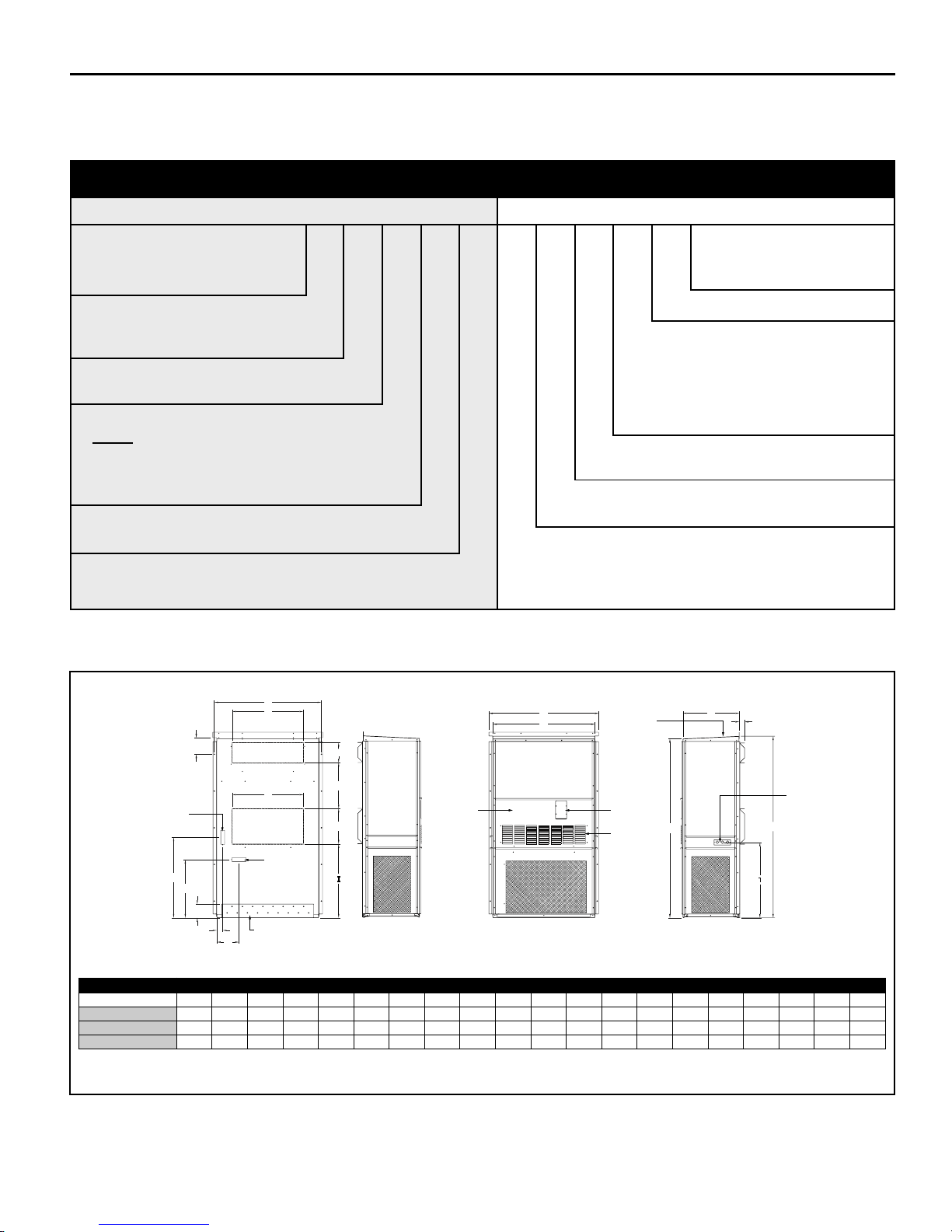
Figure 2 – Unit Dimensions
Future Revision Digit
Ventilation Options
X = Manual fresh air damper (standard)
M = Motorized fresh air damper
N = No vent option
E = Economizer
C = Commercial Room Ventilator
Chassis Color
X = Alaskan Beige (standard)
Control Options
X = Standard Controls
Electric Heat - KW Options
00 = No electric heat
05 = 5.0 KW
08 = 8.0 KW
10 = 10.0 KW
15 = 15.0 KW
20 = 20.0 KW
BACK LEFT SIDE FRONT RIGHT SIDE
MODEL DIMENSIONS
OES/OHS18 & 24 36.9 20.0 6.2 7.9 20.1 20.0 11.9 31.5 28.5 22.8 5.0 2.3 9.8 37.9 35.9 22.4 70.1 2.0 71.1 29.5
OES/OHS30 & 36 41.9 28.0 6.2 7.9 17.9 27.9 14.0 31.5 28.8 22.8 5.0 2.3 8.7 42.9 40.9 22.4 70.1 2.0 71.1 29.5
OES/OHS42, 48, & 60 43.9 29.9 6.3 9.9 29.9 29.9 15.9 33.5 27.3 23.8 5.0 3.5 13.0 49.9 42.8 27.4 84.0 2.0 85.9 36.8
* Due to our pollicy of continuous improvement, all specifications are subject to change without notice.
A B C D E F G H I J K L M N O P Q R S T
3

5
920-138-02 (3-04)
920-138-02 (3-04)
DANGER: Before installing or servicing system, always turn off main power to system. There may be more than one
(1) disconnect switch. Turn off auxiliary heater power if applicable. Electrical shock can cause personal injury or death.
II. INSTALLATION
Introduction
NOTE: Read the entire instruction manual before starting
the installation.
The OES/OHS series air conditioners and heat pumps are
ETL and c-ETL listed and are available in the cooling/electric
heating sizes shown in Table 5 on page 13. This series of
units is designed for outside installation only.
The OES/OHS series air conditioners and heat pumps are
self-contained units. All components, including outdoor coil,
compressor, and refrigerant tubing, are located in a single
package. The units are already piped, charged, and wired.
Refer to Figure 2 on page 3 for basic unit dimensions.
The OES/OHS series air conditioners and heat pumps are
designed for installation in various light commercial applications.
These instructions detail a typical method of installation. These
units can be installed with or without ductwork. Installed
anges can be used for attaching ductwork or covered with a
decorative grille. OES/OHS series units come from the factory
with two 1" air lters installed. Simply bend tabs on lter rack
to accommodate 2" lters. Return lter grills are offered as
an accessory option. If a different or additional air lters are
required, they will need to be eld-installed in the duct system.
These units have 2" long duct anges for connecting to the
eld ducts.
Safety Considerations
Improper installation, adjustment, alteration, ser vice,
maintenance, or use can cause explosion, re, electrical
shock, or other conditions which may cause personal injury or
property damage. Consult a qualied installer, service agency,
or your distributor or dealer for information and assistance.
The qualied installer or agency must use factory-authorized
parts or accessories when modifying this product. Refer to the
individual instructions packaged with the parts or accessories
when installing.
Follow all safety codes. Wear the proper attire, including
safety glasses and work gloves. Read these instructions
thoroughly and follow all warnings or cautions attached to the
unit. Consult local building codes, the National Electric Code
(NEC), and the Installation Standards, Warm Air Heating
and Air Conditioning Systems ANSI/NFPA 90B for special
installation requirements.
Recognize safety information. This is the safety-alert symbol:
When you see this symbol on the unit or in instructions
and manuals, be alert to the potential for personal injury.
Understand the signal words DANGER, WARNING, and
CAUTION. These words are used with the safety-alert symbol.
DANGER identies the most serious hazards which will result
in severe personal injury or death. WARNING signies hazards
which could result in personal injury or death. CAUTION is
used to identify unsafe practices which would result in minor
personal injury or product and property damage. NOTE is used
to convey special or supplemental information or to repeat and
emphasize information previously provided.
General Recommendations
(Do's and Do Not's)
The installation of this unit must comply with all local and
national electrical and installation codes. Where local
regulations differ with these instructions, local codes must
apply.
• Do read the instructions completely before installation.
• Do take time to perform a quality installation.
• Supply and return air ductwork must be properly sized
for this equipment. All ductwork should be insulated to
prevent condensation and water damage.
• Do tape and seal all duct joints.
• Do check the indoor conditioned air duct system static
pressure losses. It should not exceed those listed for
these units. Consult your dealer or distributor for more
information.
• When designing indoor supply systems, do not reduce
air intake or discharge sizes.
• Do insulate all conditioned air duct system
components.
• Do locate thermostat on an interior wall.
• Do check that condensate drain line drains freely.
• Do provide minimum installation and service
clearances.
• Do follow all guidelines for indoor and outdoor air
system.
• Do not drill into unit (except for 2 in. anges for ducted
return units). This could cause a refrigerant leak.
• Do not substitute any components without checking
with your dealer or distributor. If you do substitute, get
approval in writing. Substitutions without approval void
unit warranty.
• Do not guess. Consult your dealer or distributor if any
portion of the installation procedure is unclear.
4
920-138-02 (3-04)
Installer Qualications
This equipment is intended to be installed by a qualied HVAC
specialist who is experienced and thoroughly knowledgable
in air conditioning unit installation and operation, high voltage
electrical systems, ductwork construction and airow, and
thermostat installation. All instructions for this unit as well
as separate equipment should be read completely before
attempting installation.
Inspection
Remove shipping protection and pallet from unit and inspect
for damage. Be sure to check for concealed internal shipping
damage. Do not install a damaged unit. Damage should be
reported to the last motor carrier to handle the shipment and a
request (written is preferred) should be made for an inspection
by the carriers agent.
Supplies Needed for Installation
The following items are required to install unit:
• Seven-conductor thermostat cable for OHS series, and
5-conductor thermostat cable for OES series. (20 gage
wire minimum).
• Supplies to connect indoor air (conditioned air supply)
duct to unit.
• Supplies to connect power to the unit.
• Supplies to connect low-voltage thermostat to unit.
Service Clearance and Unit Location
A minimum of 30 in. service clearance must be allowed in front
of the unit, and a minimum of 20 in. on either side. Additional
clearance may be necessary. Most serviceable components
are accessible from the front of the unit with the front panels
removed.
INDOOR AIR REQUIREMENTS
The indoor air system is designed to operate at specied
airow rates and external static pressures. The supply and
return air duct system pressure losses (including lter, louver/
grille and registers) must not exceed the listed external static
pressures for the indoor air system.
!
CAUTION: Failure to adhere to indoor air requirements as
listed in the following section will void the unit warranty.
Indoor Air (Conditioned Supply Air)
System
The unit may be applied in either a free return air conguration
or a ducted return air conguration. The design and construction
of the indoor-air system must provide adequate air distribution
to ensure comfort levels throughout the structure. All ductwork
must be properly sized for the designed air ow of the unit. All
duct work should be properly insulated to conserve energy and
prevent condensation damage. Where the duct runs through
unheated spaces, it should be insulated with at least one inch
of insulation. Insulation with a vapor barrier on the outside
should be used. Use exible joints to connect the ductwork to
the unit to reduce noise transmission into the structure. See
Figure 2 for additional information.
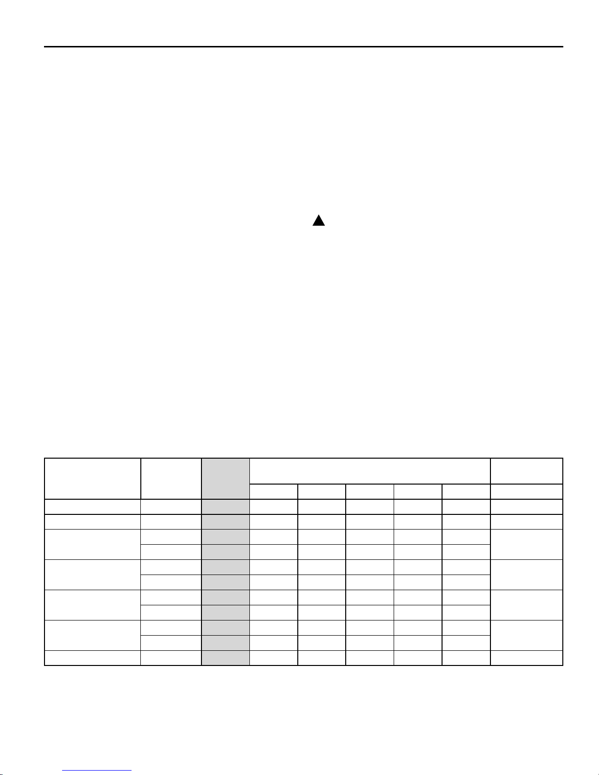
Table 1 – Indoor Air System Data
Model Motor Speed
OES18K / OHS18K
OES24K / OHS24K
OES30K / OHS30K
OES36K / OHS36K
OES42K / OHS42K
OES48K / OHS48K
OES60K / OHS60K
NOTE: Italic font indicates performance is outside the required operating window.
–
–
Low 1280 1140 985
High
Low 1280 1140 985
High
Low 1690 1645 1550 1450 1300
High
Low 1690 1645 1550 1450 1300
High
–
Rated
SCFM
650
800
1000
1150
1400
1550
1900
0.1 0.2 0.3 0.4 0.5
840 750 650
840 750 650
1370 1220 1060
1370 1220 1060
1895 1795 1690 1565 1340
1895 1795 1690 1565 1340
2350 2200 2060 1900 1730 1800-2200
E.S.P. (Wet Coil)
440
440
800
885
800
885
Recommended
Airow Range
250 585-720
250 720-880
615
665
615
665
900-1100
1015-1240
1260-1540
1395-1720
5
7
920-138-02 (3-04)
920-138-02 (3-04)
!
CAUTION: If return air ducting is not used, an adequately
sized metal return air grille is required. Velocity should not
exceed 500 FPM for return air grilles, and 400 FPM for lter
grilles. It is recommended that the proper Friedrich return air
grille kit be installed in applications where no return duct is
used.
FILTERS
Two replaceable air lters are supplied from the factory. The
lters are accessible through the access panels on the sides of
the unit
the return air grille.
The combined pressure losses of the return and supply air
paths must not exceed the external static capabilities of the
system at the design airow (See Table 1).
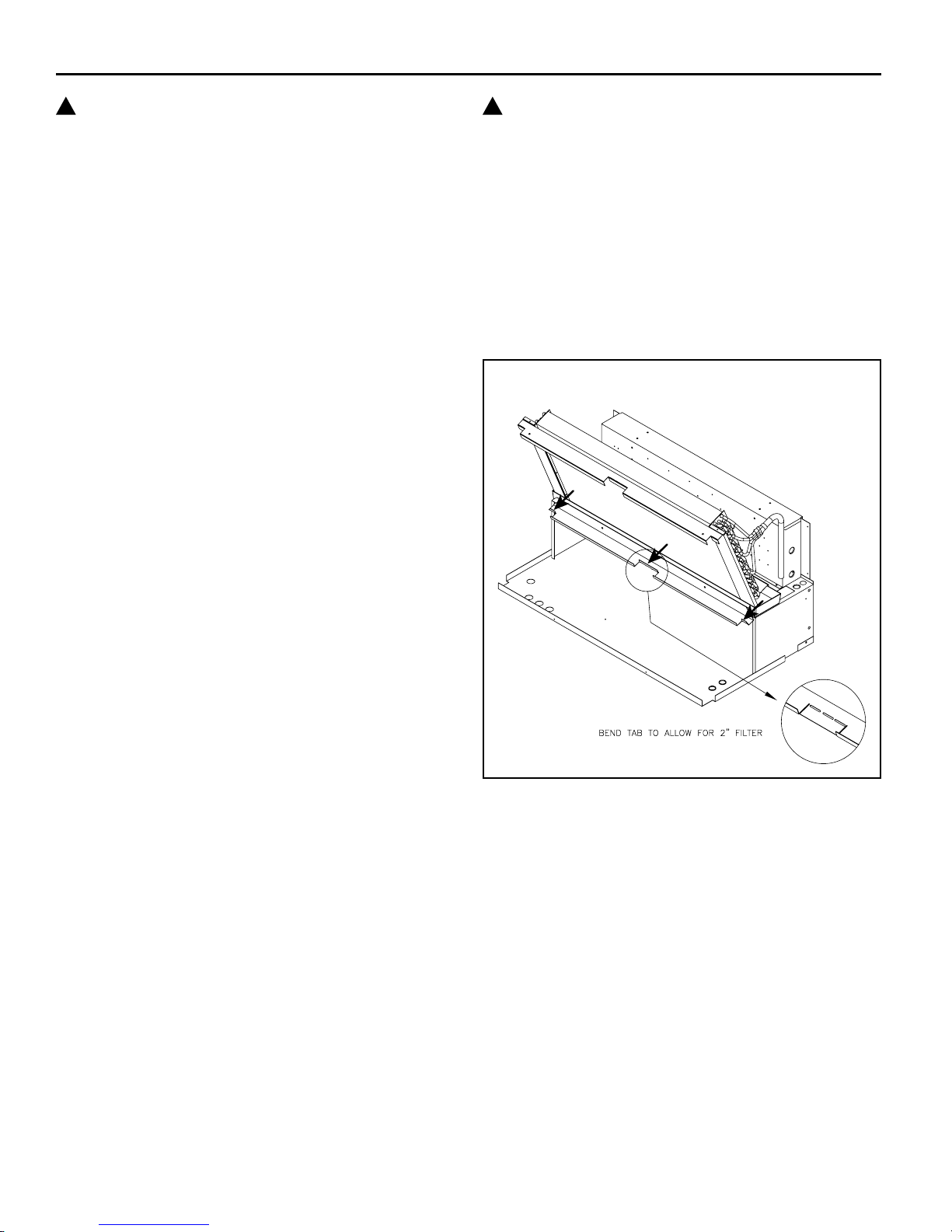
The factory-installed lter rails are designed to hold 1" or 2"
lters. When using 2" lters the lter rail divider tabs must be
folded at (See Figure 3).
NOTE: Dirty lters are the most common cause of inadequate
heating and cooling performance.
(See Figure 2) or from the inside of the building through
• Inspect lters monthly
• Replace disposable type lters before they become
clogged
• Use water and mild detergent to clean washable type
lters
!
CAUTION: To ensure proper operation, the outdoor air
intake and discharge air paths must be free and unobstructed
for the rst 20 inches. The two air paths must be unrestricted
to ensure that the intake and discharge air do not recirculate
(also called short-circuit).
CONDENSATE DRAINAGE
A plastic drain hose extends from the drain pan to the vent at
the bottom of the unit. This line can be attached to a suitable
drainage system. If this is done, the system must be vented
or open type to ensure proper drainage. Condensate water
can freeze in cold weather which could create hazardous
situations.
Figure 3 - Filter Rail Adjustment
NOTE: Most lters are marked with an arrow to indicate the
proper direction of air ow through the lter. The arrow MUST
point in the direction of air ow.
OUTDOOR AIR SYSTEM
As a completely self-contained system, OES/OHS series units
require an adequate supply of outdoor air to exchange heat
from the outdoor air coil. The outdoor air intake and discharge
openings are located on the front and sides of the unit.
6
920-138-02 (3-04)
�
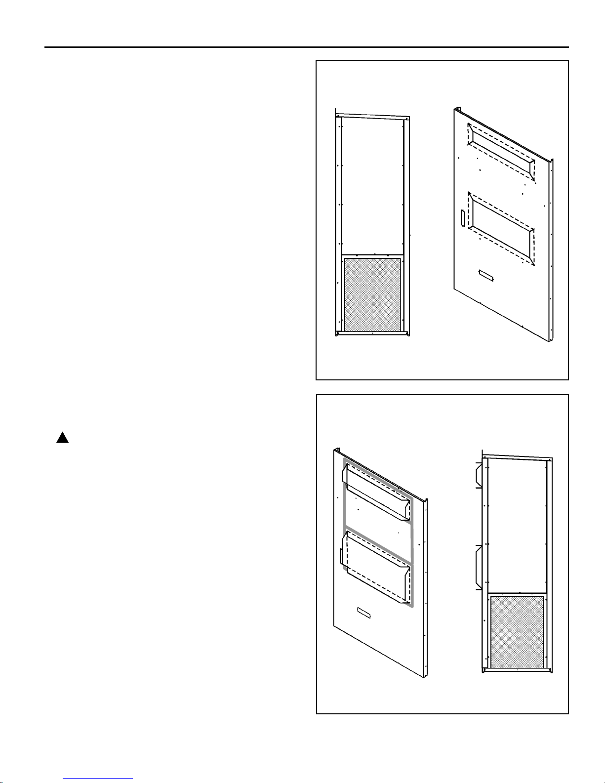
MOUNTING PREPARATIONS
Forming the Duct Flanges
To minimize the possibility of shipping damage, all units are
shipped with eld formed duct anges. These anges must
all be formed into place prior to mounting the unit.
The perforated bend lines of the duct flanges provide
a location for eld hand bending/forming to occur in a
repeatable manner. When forming the anges, begin at the
upper most perforations and work from top to bottom. The
procedures for bending the duct anges are as follows:
• Face the back side of the unit, which is the side that will
ultimately make contact with the mounting surface. (See
Figure 4.)
• Wearing protective gloves, grasp the center of the
metal ange with both hands and gradually bend
outward at approximately a 45 degree angle.
• Continue this process until the entire length of the
ange is bent to a 45 degree angle.
• Starting back in the center, grasp the ange with both
hands and complete the bend to 90 degrees along the
entire length. The ange should now be perpendicular
to the rear of the cabinet. (See Figure 5.)
• Repeat the above steps for each of the eight
perforated metal anges on the rear of the cabinet.
When completed, there will be eight duct anges that
are perpendicular to the rear of the cabinet. (See
Figure 5.)
CAUTION: Repeated bending of the anges from
at to the perpendicular position will eventually weaken
the sheet metal and ultimately cause failure of the metal
anges.
Figure 4
Duct Flanges as Shipped
Left Side Duct Flanges as Shipped
Figure 5
Formed Duct Flanges with Gaskets Installed
Installing Sealing Gaskets
In order to ensure a proper air seal between unit and the
building, the factory-supplied sealing gaskets must be
applied. Failure to install the gaskets may result in air leaks
and poor unit performance.
• Facing the mounting side of the unit, retrieve the
sealing gaskets from the return air opening of the
unit.
• Next, apply a piece of the gasket vertically to both
the left and right side of the air openings as shown.
• With the remaining gasket, seal the top and bottom
of both the supply and return air opening as shown.
Gaskets may be cut with a utility knife or torn by hand to
the proper length.
Formed Duct Flanges
Left Side
7
9
920-138-02 (3-04)
920-138-02 (3-04)
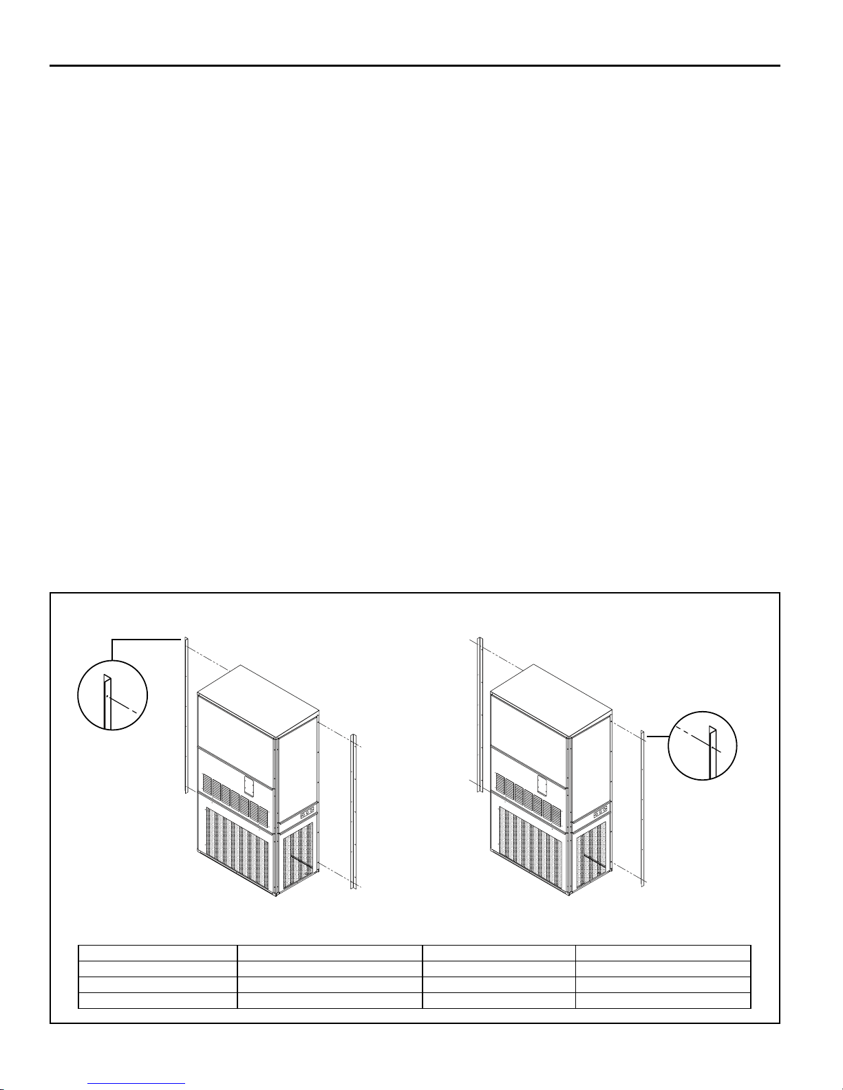
MOUNTING THE UNIT
Mounting Information
Two holes must be cut in the wall for the supply and return air
openings. (See Figures 7 and 8)
On wood frame walls, the wall may need to be reinforced in
order to hold up to the weight of the unit.
Concrete block walls must be thoroughly inspected to insure
that they can handle the unit weight.
It is the installer's responsibility to insure that hardware used
for mountng of unit is correct for wall material.
New Installation
OES/OHS units are afxed to the wall by way of three
mounting brackets. The bottom bracket supports the majority
of the weight load, and the side brackets hold the unit in place
(See Figures 6 and 7).
Friedrich recommends a 1 inch clearance to combustible
material for the rst 3 feet of duct attached to the outlet air
frame.
1. Locate and mark lag bolt locations and bottom
mounting bracket location. (See Figure 8)
2. Mount bottom mounting bracket.
3. Connect the side mounting brackets to the rear
corner posts of the unit. Brackets may be mounted
with anges outward or inward. See Figure 6
for dimensions for new installation. Friedrich
recommends installing the brackets outward.
4. Connect the rain ashing to the back ange of the
unit top by using screws in the top panel. Top rain
ashing is shipped secured to the back of the unit.
(See Figure 9)
5. Position the unit in the opening and secure to the
wall with 5/16 inch lag bolts; use 7/8 inch diameter
at washers on the lag bolts.
6. Secure the rain ashing to the exterior wall and
across the entire length of the top. (See Figure 9
caulk
)
7. On side by side installations, maintain a minimum
of 20 inches clearance on both sides to allow
access to heat strips and to allow proper airow
out of the outdoor coil. Additional clearance may
be required to meet local or national codes.
Replacement Installation
Friedrich mounting brackets are removable and can be
mounted in two ways to ensure the bracket holes are in line
with the studs. (See Figure 6)
When doing a replacement project measure the space
between the studs, then look at the chart below, which gives
the space between mounting brackets for all chassis sizes.
Decide in which position the brackets should be mounted
to best match the stud spacing. If the unit is to be installed
with the brackets facing outwards, (Figure 6) rst mount the
brackets onto the unit and then secure to the wall. If the unit
is to be installed with the brackets facing inwards (Figure
6), rst mount brackets to the wall, then position the unit up
against the wall and secure brackets to the unit.
Figure 6
Flange Outward
Flanges Outward
Mount anges to chassis rst
Mounting Options
Flanges Inward
Mount anges to wall rst
MODEL Flange outward MODEL Flange inward
OES/OHS18&24 36.9 OES/OHS18&24 33.9
OES/OHS30&36 41.9 OES/OHS30&36 38.9
OES/OHS42,48&60 43.9 OES/OHS42,48&60 40.8
Flange Inward
8
 Loading...