


Wall-Mount
OutdoorWall-mounted Air Conditioners/ Heat Pumps
OES/ OHSSeries
Installation & Operation Manual
920-138-02 (3-04)

920-138-02(3-04)
TABLE OF CONTENTS
I. General Specifications
Model Number Identification Guide ............................................................. 3
Unit Dimensions ............................................................................ 3
II. Installation
Introduction ................................................................................ 4
Safety Considerations ........................................................................ 4
Indoor Air Requirements ...................................................................... 5
Filters ..................................................................................... 6
Outdoor Air System .......................................................................... 6
Condensate Drainage ........................................................................ 6
Mounting Preparations ....................................................................... 7
Mounting the Unit ......................................................................... 8-9
Rain Flashing Installation .................................................................... 10
Thermostat Wiring .......................................................................... 11
Line Voltage Electrical Wiring ................................................................. 11
Electrical Data Tables ..................................................................... 12-13
Standard Ventilation Package ................................................................. 14
Optional Ventilation Packages .............................................................. 15-17
III. Start Up
Sequence of Operation ...................................................................... 18
Defrost Cycle (Heat Pump models only) ........................................................ 18
Final Installation Checklist .................................................................... 18
IV. Service / Warranty
Service Hints .............................................................................. 18
Model Information Form ..................................................................... 19
Warranty Information ..................................................................... 20-21
Please read this manual thoroughly prior to equipment installation or operation. It is the installer's responsibility to properly apply
and install the equipment. Installation must be in conformance with the NFPA 70-2002 National Electric Code or current edition
and Universal Mechanical Code current edition and applicable local or national codes.
Remember, proper installation is not difficult but it is essential.
Inspect for Shipping Damage
You should inspect your shipment immediately for signs of external damage. Any damage found should be reported
(preferably in writing) to the last carrier to handle the shipment and a request for inspection by their agent made.
Any hidden damage should also be reported when the unit is unpacked.
920-138-02 (3-04)
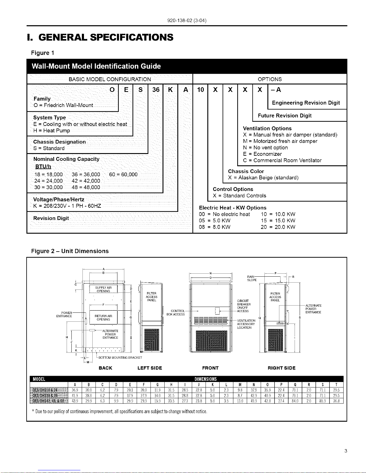
I. GENERAL SPECIFICATIONS
Figure 1
BASIC MODEL CONFIGURATION
O S
Family E
O = Friedrich Wall-Mount I
System Type
E = Cooling with or without electric heat
H = Heat Pump
Chassis Designation
S = Standard
Nominal Cooling Capacity
BTU/h
18 = 18.000 36 = 36.000 60 = 60.000
24 = 24.000 42 = 42.000
30 = 30.000 48 = 48.000
Voltage/Phase/Hertz
K = 208/230V - 1 PH - 60HZ
36 K
10 X X
OPTIONS
X X [-A
Engineering Revision Digit
Future Revision Digit
Ventilation Options
X = Manual fresh air damper (standard)
M = Motorized fresh air damper
N = No vent option
E = Economizer
C = Commercial Room Ventilator
Chassis Color
X = Alaskan Beige (standard)
Control Options
X = Standard Controls
Revision Digit
08 = 8.0 KW
Electric Heat - KW Options
00 = Noelectric heat 10 = 10.0 KW
05 = 5.0 KW 15 = 15.0 KW
20 = 20.0 KW
Figure 2 - Unit Dimensions
c
RAIN --P_ --R
SUPPLY AIR [
. OPENING .
]
FILTER
ACCESS
E PANEL
CONTROL
BOX ACCESS
FILTER
ACCESS
CIRCUIT PANEL
BREAKER
ON/OFF
ACCESS L
Q s
VENTILATION = =
ACCESSORY
LOCATION
_ T
.1
ALTERNATE
POWER
ENTRANCE
BACK LEFT SIDE FRONT RIGHT SIDE
lt'#l'], ']li'll_iiIPlil
A B C D E F G 14 I J K L M N 0 P O R S T
36.9 200 6.2 79 20.1 20.0 119 315 285 228 50 23 98 37.9 35.9 224 701 20 711 29.5
419 280 6.2 79 179 27.9 140 315 288 228 50 23 8.7 42.9 409 224 701 20 711 29.5
439 299 6.3 99 299 29.9 15.9 33.5 273 238 50 35 13.0 49.9 42.8 274 84.0 20 85.9 36.8
* Duetoourpolticyofcontinuousimprovement,allspecificationsaresubjecttochangewithoutnotice.

920-138-02 (3-04)
I _1, DANGER: Before installing or servicing system, always turn off main power to system. There may be more than one I(1) disconnect switch. Turn off auxiliary heater power if applicable. Electrical shock can cause personal injury or death.
I
II. INSTALLATION
Introduction
NOTE: Read the entire instruction manual before starting
the installation.
The OES/OHS series air conditioners and heat pumps are
ETL and c-ETL listed and are available inthe cooling/electric
heating sizes shown in Table 5 on page 13. This series of
units is designed for outside installation only.
The OES/OHS series air conditioners and heat pumps are
self-contained units. All components, including outdoor coil,
compressor, and refrigerant tubing, are located in a single
package. The units are already piped, charged, and wired.
Refer to Figure 2 on page 3 for basic unitdimensions.
The OES/OHS series air conditioners and heat pumps are
designed for installation invarious light commercial applications.
These instructions detail atypical method of installation. These
units can be installed with or without ductwork. Installed
flanges can be used for attaching ductwork or covered with a
decorative grille. OES/OHS series units come from the factory
with two 1"air filters installed. Simply bend tabs on filter rack
to accommodate 2" filters. Return filter grills are offered as
an accessory option. If a different or additional air filters are
required, they will need to be field-installed inthe duct system.
These units have 2" long duct flanges for connecting to the
field ducts.
Safety Considerations
Improper installation, adjustment, alteration, service,
maintenance, or use can cause explosion, fire, electrical
shock, orother conditions which may cause personal injury or
property damage. Consult a qualified installer, service agency,
or your distributor or dealer for information and assistance.
The qualified installer or agency must use factory-authorized
parts or accessories when modifying this product. Refer to the
individual instructions packaged with the parts or accessories
when installing.
Follow all safety codes. Wear the proper attire, including
safety glasses and work gloves. Read these instructions
thoroughly and follow allwarnings or cautions attached to the
unit. Consult local building codes, the National Electric Code
(NEC), and the Installation Standards, Warm Air Heating
and Air Conditioning Systems ANSI/NFPA 90B for special
installation requirements.
Recognize safety information. This is the safety-alert symbol:
_, When you see this symbol on the unit or in instructions
and manuals, be alert to the potential for personal injury.
Understand the signal words DANGER, WARNING, and
CAUTION. These words areused with the safety-alert symbol.
DANGER identifies the most serious hazards which will result
insevere personal injury or death. WARNING signifies hazards
which could result in personal injury or death. CAUTION is
used to identify unsafe practices which would result in minor
personal injury or product and property damage. NOTE isused
to convey special or supplemental information or to repeat and
emphasize information previously provided.
General Recommendations
(Do's and Do Not's)
The installation of this unit must comply with all local and
national electrical and installation codes. Where local
regulations differ with these instructions, local codes must
apply.
• Do read the instructions completely before installation.
• Do take time to perform a quality installation.
• Supply and return airductwork must be properly sized
for this equipment. All ductwork should be insulated to
prevent condensation and water damage.
• Do tape and seal all ductjoints.
• Do check the indoor conditioned air duct system static
pressure losses. Itshould not exceed those listedfor
these units. Consult your dealer or distributor for more
information.
When designing indoor supply systems, do not reduce
air intake or discharge sizes.
Do insulate all conditioned air duct system
components.
Do locate thermostat on an interior wall.
Do check that condensate drain line drains freely.
Do provide minimum installation and service
clearances.
• Do follow all guidelines for indoor and outdoor air
system.
• Do not drill into unit (except for 2 in. flanges for ducted
return units). This could cause a refrigerant leak.
• Do not substitute any components without checking
with your dealer or distributor, lfyou do substitute, get
approval in writing. Substitutions without approval void
unitwarranty.
• Do not guess. Consult your dealer ordistributor if any
portion of the installation procedure is unclear.

920-138-02 (3-04)
Installer Qualifications
This equipment isintended to be installed by a qualified HVAC
specialist who is experienced and thoroughly knowledgable
in air conditioning unit installation and operation, high voltage
electrical systems, ductwork construction and airflow, and
thermostat installation. All instructions for this unit as well
as separate equipment should be read completely before
attempting installation.
Inspection
Remove shipping protection and pallet from unit and inspect
for damage. Be sure to check for concealed internal shipping
damage. Do not install a damaged unit. Damage should be
reported to the last motor carrier to handle the shipment and a
request (written is preferred) should be made foran inspection
by the carriers agent.
Supplies Needed for Installation
The following items are required to install unit:
• Seven-conductor thermostat cable for OHS series, and
5-conductor thermostat cable for OES series. (20 gage
wire minimum).
• Supplies to connect indoor air (conditioned air supply)
duct to unit.
• Supplies to connect power to the unit.
• Supplies to connect low-voltage thermostat to unit.
Service Clearance and Unit Location
A minimum of 30 in.service clearance must be allowed infront
of the unit, and a minimum of 20 in. on either side. Additional
clearance may be necessary. Most serviceable components
are accessible from the front of the unit with the front panels
removed.
INDOOR AIR REQUIREMENTS
The indoor air system is designed to operate at specified
airflow rates and external static pressures. The supply and
return air duct system pressure losses (including filter, louver/
grille and registers) must not exceed the listed external static
pressures for the indoor air system.
_, CAUTION: Failure toadhere to indoor air requirements as
listed in the following section will void the unit warranty.
Indoor Air (Conditioned Supply Air)
System
The unit may beapplied ineither afree return airconfiguration
or a ducted returnairconfiguration. The design and construction
of the indoor-air system must provide adequate airdistribution
to ensure comfort levelsthroughout the structure. All ductwork
must be properly sized for the designed air flow of the unit. All
duct work should be properly insulated to conserve energy and
prevent condensation damage. Where the duct runs through
unheated spaces, it should be insulated with at least one inch
of insulation. Insulation with a vapor barrier on the outside
should be used. Use flexible joints to connect the ductwork to
the unit to reduce noise transmission into the structure. See
Figure 2 for additional information.
Table 1 - Indoor Air System Data
Model
OE$18K/ OHS18K
OES24K/ OH$24K
OES30K/ OHS30K
OES36KtOHS36K
OES42KtOHS42K
OES48K/OHS48K
OES60KtOHS60K
MotorSpeed
Low
High
Low
High
Low
High
Low
High
0.1
840
840
1280
1370
1280
1370
1690
1895
1690
1895
2350
E.S.R
0.2
750
750
1140
1220
1140
1220
1645
1795
1645
1795
2200
(Wet Coil)
0.3
65O
65O
965
1060
985
1060
1550
1690
1550
1690
2060
0.4
440
440
808
885
808
885
1450
1565
1450
1565
1900
0.5
250
250
615
665
615
665
1300
1340
1300
1340
1730
Recommended
Airflow Range
585-720
720-880
900-1100
1015-1240
1260-1540
1395-1720
1800-2200
NOTE: italic font indicates performance is outside the required operating window.

920-138-02(3-04)
_, CAUTION: Ifreturn air ducting is not used, an adequately
sized metal return air grille is required. Velocity should not
exceed 500 FPM for return air grilles, and 400 FPM for filter
grilles. It is recommended that the proper Friedrich return air
grille kit be installed in applications where no return duct is
used.
FILTERS
Two replaceable air filters are supplied from the factory. The
filters are accessible through the access panels on the sides of
the unit (See Figure2) or from the inside of the building through
the return airgrille.
The combined pressure losses of the return and supply air
paths must not exceed the external static capabilities of the
system at the design airflow (See Table 1).
The factory-installed filter rails are designed to hold 1" or 2"
filters. When using 2" filters the filter rail divider tabs must be
folded flat (See Figure 3).
NOTE: Dirty filters are the most common cause of inadequate
heating and cooling performance
• Inspect filters monthly
• Replace disposable type filters before they become
clogged
• Use water and mild detergent to clean washable type
filters
NOTE: Most filters are marked with an arrow to indicate the
proper direction of air flow through the filter The arrow MUST
point in the direction of air flow
OUTDOOR AIR SYSTEM
As a completely self-contained system, OES/OHS series units
require an adequate supply of outdoor air to exchange heat
from the outdoor air coil. The outdoor air intake and discharge
openings are located on the front and sides of the unit.
_IL CAUTION: To ensure proper operation, the outdoor air
intake and discharge air paths must be free and unobstructed
for the first 20 inches. The two air paths must be unrestricted
to ensure that the intake and discharge air do not recirculate
(also called short-circuit).
CONDENSATE DRAINAGE
A plastic drain hose extends from the drain pan to the vent at
the bottom of the unit. This line can be attached to a suitable
drainage system. If this is done, the system must be vented
or open type to ensure proper drainage. Condensate water
can freeze in cold weather which could create hazardous
situations.
Figure 3 - Filter Rail Adjustment
BEND TAB TO i, LLO_&' FOR 2" FLTER

920-138-02 (3-04)
MOUNTING PREPARATIONS
Forming the Duct Flanges
To minimize the possibility of shipping damage, all units are
shipped with field formed duct flanges. These flanges must
all be formed into place prior to mounting the unit.
The perforated bend lines of the duct flanges provide
a location for field hand bending/forming to occur in a
repeatable manner. When forming the flanges, begin at the
upper most perforations and work from top to bottom. The
procedures for bending the duct flanges are as follows:
• Face the back side ofthe unit,which is the side that will
ultimately make contact with the mounting surface. (See
Figure 4.)
• Wearing protective gloves, grasp the center of the
metal flange with both hands and gradually bend
outward at approximately a 45 degree angle.
• Continue this process until the entire length of the
flange is bent to a 45 degree angle.
• Starting back in the center, grasp the flange with both
hands and complete the bend to 90 degrees along the
entire length. The flange should now be perpendicular
to the rear of the cabinet. (See Figure 5.)
• Repeat the above steps for each of the eight
perforated metal flanges on the rear of the cabinet.
When completed, there will be eight duct flanges that
are perpendicular to the rear of the cabinet. (See
Figure 5.)
_, CAUTION: Repeated bending of the flanges from
flat to the perpendicular position will eventually weaken
the sheet metal and ultimately cause failure of the metal
flanges.
Installing Sealing Gaskets
In order to ensure a proper air seal between unit and the
building, the factory-supplied sealing gaskets must be
applied. Failure to install the gaskets may result in air leaks
and poor unit performance.
• Facing the mounting side of the unit, retrieve the
sealing gaskets from the return air opening of the
unit.
• Next, apply a piece of the gasket vertically to both
the left and right side of the air openings as shown.
• With the remaining gasket, seal the top and bottom
of both the supply and return air opening as shown.
Gaskets may be cut with a utility knife or torn by hand to
the proper length.
Figure 4
Duct Flanges as Shipped
Left Side
Duct Flanges as Shipped
Figure 5
Formed Duct Flanges with Gaskets Installed
Formed Duct Flanges
Left Side

920-138-02 (3-04)
MOUNTING THE UNIT
Mounting Information
Two holes must be cut inthe wall for the supply and return air
openings. (See Figures 7 and 8)
On wood frame walls, the wall may need to be reinforced in
order to hold up to the weight of the unit.
Concrete block walls must be thoroughly inspected to insure
that they can handle the unit weight.
It is the installer's responsibility to insure that hardware used
for mountng of unit is correct for wall material.
New Installation
OES/OHS units are affixed to the wall by way of three
mounting brackets. The bottom bracket supports the majority
of the weight load, and the side brackets hold the unit in place
(See Figures 6 and 7).
Friedrich recommends a 1 inch clearance to combustible
material for the first 3 feet of duct attached to the outlet air
frame.
1. Locate and mark lag bolt locations and bottom
mounting bracket location. (See Figure 8)
2. Mount bottom mounting bracket.
3. Connect the side mounting brackets to the rear
corner posts of the unit. Brackets may be mounted
with flanges outward or inward. See Figure 6
for dimensions for new installation. Friedrich
recommends installing the brackets outward.
4. Connect the rain flashing to the back flange of the
unit top by using screws in the top panel. Top rain
flashing is shipped secured to the back of the unit.
(See Figure 9)
5. Position the unit in the opening and secure to the
wall with 5/16 inch lag bolts; use 7/8 inch diameter
flat washers on the lag bolts.
6. Secure the rain flashing to the exterior wall and caulk
across the entire length of the top. (See Figure 9)
7. On side by side installations, maintain a minimum
of 20 inches clearance on both sides to allow
access to heat strips and to allow proper airflow
out of the outdoor coil. Additional clearance may
be required to meet local or national codes.
Replacement Installation
Friedrich mounting brackets are removable and can be
mounted in two ways to ensure the bracket holes are in line
with the studs. (See Figure 6)
When doing a replacement project measure the space
between the studs, then look at the chart below, which gives
the space between mounting brackets for all chassis sizes.
Decide in which position the brackets should be mounted
to best match the stud spacing. If the unit is to be installed
with the brackets facing outwards, (Figure 6) first mount the
brackets onto the unit and then secure to the wall. If the unit
is to be installed with the brackets facing inwards (Figure
6), first mount brackets to the wall, then position the unit up
against the wall and secure brackets to the unit.
Figure 6
Mounting Options
Flange Outward
Flange Inward
MODEL
OES/OHSl8&24
OES/OHS30&36
OES/OHS42,48&60
Flanges Outward
Mount flanges to chassis first
Flanges Inward
Mount flanges to watt first
Flange outward
36.9
41.9
43.9
MODEL
OES/OHS18&24
OES/OHS30&36
OES/OHS42,48&60
Flange inward
33.9
38.9
40.8

Concrete Block Wall
Installation
920-138-02 (3-04)
Figure 7
Wall Mounting Instructions
IIII
SUPPLY AIR
OPENING
RETURN AIR
OPENING
• o o • • • •
Wood Frame Wall
Installation
Factory
supplied rain
flashing.
Mount on
unit before
installing
=:=====_
Wall Structure
_ Supply Air
__ Duct
Return Air
Opening
m
Bottom mounting
bracket. Mount on wall
before installing unit.
Figure 8
1 I
I I
1 I /'
/ 1 I
Wall Framing Instructions
Attach to top of wall
I I
I I
I I
I
all around
Interior finished
wall over frame
1" clearance
all around
I I Bottom mounting
bracket: mount
I I on wall before
installing unit.
I
Framing Material:
2 x 4's, 2 x 6's and/or structural steel
See Unit Dimensions (Figure 2)
for actual dimensions
N+I.00"
RETURN
DUCT
OPENING
1.00"
t See Unit
E Dimensions
_.. (Figure 2)
for duct
dimensions
G
This structural member is positioned to
match the stud spacing for the rest of the
wall. A second member may be required
for some walls.

920-138-02 (3-04)
Figure 9 Rain Flashing Installation
Seal both sides of the rain flashing with a bead of
silicone caulking along its entire length.
Mounting Screws
Front of unit
Foam air seal
Duct Flange
IOOO
Rain Flashing (Supplied)
Mounting Face
Duct Opening in Wall
,,----Wall Structure
SUPPLY AIR
DUCT
f RETURN
AIR DUCT
NOTE: It is recommended that a
bead of silicone be placed behind
the side mounting flanges and
under the top flashing at the time
of installation
10

920-138-02(3-04)
THERMOSTAT WIRING
Attach thermostat wires to low-voltage terminal block on left side of control box in locations indicated in Figure 3.
Figure 10 - Thermostat Wiring
I Unit Terminal G R Y B W2
NOTE: B and E terminals are
used only on OHS models
Thermostat Terminal
G R
I
Compressor J
I
Auxiliary JHeat
Reversing I
Valve
I
I
I
Y B W2
E c I
I
I Common
I Emergency
Heat
I
I
I
E CorX I
Caution: Do not use thermostat wire with less than the
Table 2 - Thermostat Wire Size
Transformer FLA
VIVA
24/50 2.3
Wire Gauge
18 gauge
16 gauge
14 gauge
12 gauge
Maximum
distance in
Feet
60
100
160
250
recommended number of conductors.
_, CAUTION: Recheckwiring color code schedule tobecertain
proper terminals are connected beforeapplying power. Improper
wiring or installation may damage thermostat.
_.WARNING: Failuretoadhereto minimumwiresizes, maximum
overcurrent protection, disconnect, and grounding requirements
can cause personal injury, electric shock, or a fire hazard. All
wiring MUST comply with requirements of state and local codes
and ordinances and the national electric code.
_, WARNING: Electrical shock hazard. Turn OFF power to
heatpumpbeforeperforminganymaintenanceorremovingpanels.
Failureto do so can resultin personal injury and/or death.
LINE VOLTAGE ELECTRICAL WIRING
_IL DANGER: Electrical shock hazard. Turn OFF electric
power at the fuse box or service panel before making any
electrical connections and ensure a proper ground connection
is made before connecting line voltage. Failure to do so can
result in property damage, personal injury and/or death.
Grounding
_, CAUTION: The unit must be electrically wired and
grounded in accordance with all state and local codes,
national electric code, and NFPA 70. Unit and controls will
NOT operate unless properly grounded. A ground lug is
provided for ground connection. Use only approved copper
wire and connectors from unit to service panel. Ground lug
and line voltage connection terminals are located behind the
circuit breaker panel of the control box. Complete the ground
wire connection. After completing ground wire connection,
complete line voltage connections.
Low Voltage Wiring
All equipment is provided with 230/208 Volt, dual primary
voltage transformers. The factory setting is to wire them on
the 230V tap. If they need to be rewired to the 208V tap,
reconnect from the 230 to the 208V tap. The acceptable
operating voltage range for the 230 and 208V taps are shown
below. (The voltage should be measured at the field power
connection point in the unit and while the unit is operating at
full load (maximum amperage operating condition.))
NOTE: The operating voltage range for 230V is 253-216. For
the 208, it is 220-197.
High Voltage Wiring
1. Ensure that the power supply matches the correct
voltage, phase and ampacity for the selected model.
(See Tables 3 and 4)
2. The field wiring used must be sized to carry the units
maximum circuit ampacity.
3. In order to operate a nominal 230/208V unit at 208V
the transformer line tap should be changed from 240V
to 208V following the wiring label diagram in the unit.
4. Connect wires to the input side of the internal breaker
and install the ground wire on the ground lug.
11

920-138-02(3-04)
Table 3 - Electrical Data
Air Conditioners
Factory Voltage/ Hz Voltage MCA
Circuit
/ Ph Range
Breakers
Ckt 1 Ckt 2
OES18KA 00 1 230/208-60-1 198-253 15.0 N/A
05 2 230/208-60-I 198-253 15.0 26.0
08 2 230/208-60-1 198-253 15.0 39.0
10 2 230/208-60-1 198-253 15.0 52.0
OES24KA 00 1 230/208-60-I 198-253 19.9 N/A
05 2 230/208-60-1 198-253 19.9 26.0
08 2 230/208-60-1 198-253 19.9 39.0
10 2 230/208-60-1 198-253 19.9 52.0
OES30KA 00 1 230/208-60-I 198-253 22.8 N/A
05 2 230/208-80-1 198-253 22.8 28.0
08 2 230/208-80-1 198-253 22.8 39.0
10 2 230/208-80-1 198-253 22.8 52.0
15 2 230/208-80-I 198-253 22.8 39.0
OES36KA 00 1 230/208-60-1 198-253 27.9 N/A
05 2 230/208-80-1 198-253 27.9 28.0
08 2 230/208-80-I 198-253 27.9 39.0
10 2 230/208-80-1 198-253 27.9 52.0
15 2 230/208-80-1 198-253 27.9 39.0
OES42KA 00 1 230/208-60-1 198-253 31.8 N/A
10 2 230/208-60-1 198-253 31.8 52.0
15 2 230/208-60-I 198-253 31.8 39.0
OES48KA 00 1 230/208-60-1 198-253 41.0 N/A
10 2 230/208-80-1 198-253 41.0 52.0
15 2 230/208-80-I 198-253 41.0 39.0
OES60KA 00 1 230/208-60-1 198-253 48.0 N/A
15 2 230/208-80-1 198-253 48.0 39.0
20 3 230/208-60-1 198-253 48.0 52.0/52.0
MultipleCircuits Single Circuit
HACR Wire Groung
HACR/ Max WireSize GroungWire MCA / Max Size Wire
BreakerSize (field) Size (field) Breaker (field) Size
Size (field)
Ckt 1 Ckt2 Ckt 1 Ckt2 Ckt 1 Ckt2 Ckt 1 Ckt 1 Ckt 1 Ckt1
20 N/A 12 N/A 12 N/A 15 20 10 12
20 30 12 10 12 10 28 30 10 10
20 40 12 8 12 10 41 50 6 10
20 60 12 6 12 10 53 60 6 10
30 N/A 10 N/A 10 N/A 19.9 30 10 10
30 30 10 10 10 10 28 30 10 10
30 40 10 8 10 10 41 50 6 10
30 60 10 6 10 10 53 60 6 10
40 N/A 8 N/A 10 N/A 22.8 40 8 10
40 30 8 10 10 10 29 40 8 10
40 40 8 8 10 10 42 50 6 10
40 60 8 6 10 10 55 60 6 10
40 40 8 8 10 10 81 90 4 8
40 N/A 8 N/A 10 N/A 27.9 40 8 10
40 30 8 10 10 10 29 40 8 10
40 40 8 8 10 10 42 50 6 10
40 60 8 6 10 10 55 60 6 10
40 40 8 8 10 10 81 90 4 8
50 N/A 6 N/A 10 N/A 31.8 50 6 10
50 60 6 6 10 10 55 60 6 10
50 40 6 8 10 10 81 90 4 8
60 N/A 6 N/A 10 N/A 41 60 6 10
60 60 6 6 10 10 55 60 6 10
60 40 6 8 10 10 81 90 4 8
60 N/A 6 N/A 10 N/A 48 60 6 10
60 40 6 8 10 10 83 90 4 8
60 60/60 6 6/6 10 10/10 N/A N/A N/A N/A
tfwire isappliedatambientgreaterthan30°C (86°F),consultTable310-16ofthe NEC(ANSl/NFPA70). Theampacityofnonmetallic-sheathedcable(NM),trade nameROMEX,
shallbe thatof 60°C (140°F)conductors,perthe NEC(ANSl/NFPA70)Article336-30. Ifotherthanuncoated(non-plated),60°C or75°C (140°For 167°F)insulation,copperwire
(solidwirefor10AWGandsmaller,strandedwireforlargerthan 10AWG)is used,consultapplicabletablesoftheNEC(ANSI/NFPA70).
2 Lengthshownisas measured1way alongthewire pathbetweenthe unitandthe servicepanelfor voltagedropnottoexceed10V,consultthefactoryfor longerwirelengthsif
needed.
3 Time-delayfuse,or HACRtypebreaker.
12

920-138-02(3-04)
Table 4 - Electrical Data
Heat Pumps
Factory Voltage/Hz Voltage MCA
Circuit
/Ph Range
Breakers
Cktl Ckt2
OHS18KA 00 1 230/208-60-1 198-253 15.0 N/A
05 2 230/208-60-I 198-253 15.0 26.0
08 2 230/208-60-I 198-253 15.0 39.0
10 2 230/208-60-1 198-253 15.0 52.0
OHS24KA 00 1 230/208-60-I 198-253 19.9 N/A
05 2 230/208-60-I 198-253 19.9 26.0
08 2 230/208-60-I 198-253 19.9 39.0
10 2 230/208-60-1 198-253 19.9 52.0
OHS30KA 00 1 230/208-60-I 198-253 22.8 N/A
05 2 230/208-60-I 198-253 22.8 26.0
08 2 230/208-60-1 198-253 22.8 39.0
10 2 230/208-60-I 198-253 22.8 52.0
15 2 230/208-60-I 198-253 22.8 39.0
OHS36KA 00 1 230/208-60-I 198-253 27.9 N/A
05 2 230/208-60-1 198-253 27.9 26.0
08 2 230/208-60-I 198-253 27.9 39.0
10 2 230/208-60-I 198-253 27.9 52.0
15 2 230/208-60-1 198-253 27.9 39.0
OHS42KA 0O 1 230/208-60-1 198-253 31.8 N/A
10 2 230/208-60-I 198-253 31.8 52.0
15 2 230/208-60-I 198-253 31.8 39.0
OHS48KA 00 1 230/208-60-I 198-253 41.0 N/A
18 2 230/208-60-1 198-253 41.0 52.0
15 2 230/208-60-I 198-253 41.0 39.0
OHS60KA 00 1 230/208-60-I 198-253 48.0 N/A
15 2 230/208-60-I 198-253 48.0 39.0
MultipleCircuits SingleCircuit
HACR Wire Groung
HACR/ Max Wire Size GroungWire MCA / Max Size Wire
BreakerSize (field) Size (field) Breaker (field) Size
Size (field)
Ckt 1 Ckt2 Ckt 1 Ckt2 Ckt 1 Ckt 2 Ckt 1 C_ 1 Ckt 1 Ckt 1
20 N/A 12 N/A 12 N/A 15 20 10 12
20 30 12 10 12 10 39 40 8 10
20 40 12 8 12 10 52 60 6 10
20 60 12 6 12 10 65 70 4 8
30 N/A 10 N/A 10 N/A 19.9 30 10 10
30 30 10 10 10 10 41 40 8 10
30 40 10 8 10 10 54 60 6 10
30 60 10 6 10 10 67 70 4 8
40 N/A 8 N/A 10 N/A 22.8 40 8 10
40 30 8 10 10 10 51 60 6 10
40 40 8 8 10 10 64 70 4 8
40 60 8 6 10 10 77 80 4 8
40 40 8 8 10 10 81 90 4 8
40 N/A 8 N/A 10 N/A 27.9 40 8 10
40 30 8 10 10 10 54 60 6 10
40 40 8 8 10 10 67 70 4 8
40 60 8 6 10 10 80 80 4 8
40 40 8 8 10 10 81 90 4 8
50 N/A 6 N/A 10 N/A 31.8 50 6 10
50 60 6 6 10 10 84 90 4 8
50 40 6 8 10 10 81 90 4 8
60 N/A 6 N/A 10 N/A 41 60 6 10
60 60 6 6 10 10 88 90 4 8
60 40 6 8 10 10 81 90 4 8
60 N/A 6 N/A 10 N/A 48 60 6 10
60 40 6 8 10 10 88 110 2 6
1 Ifwire is appliedatambientgreaterthan30°C (86°F),consultTable310-16ofthe NEC(ANSI/NFPA70). Theampacityof nonmetallic-sheathedcable(NM),tradenameROMEX,
shallbe thatof 60°C (140°F)conductors,perthe NEC(ANSI/NFPA70)Article336-30. If otherthan uncoated(non-plated),60°Cor 750C(140°For 167°F)insulation,copperwire
(solidwireforI0 AWG andsmaller,strandedwirefor largerthan10AWG)is used,consultapplicabletablesof theNEC(ANSI/NFPA70).
Lengthshownis asmeasured1way alongthewire pathbetweenthe unitand theservicepanelfor voltagedrop notto exceed10V,consultthefactory forlongerwirelengthsif
needed.
3 Time-delayfuse,or HACRtypebreaker.
Table 5 - Unit Sizes and Available Electric Heat
Heating Available
Unit Size Cooling BTU/h at 47°F
BTUh KW
(Heat Pump Mode)
18 17,000 17,000 5,8,10
24 24,600 23,600 5,8,10
30 30,000 25,000 5,8,10,15
36 36,000 34,600 5,8,10,15
42 42,000 42,000 10,!5
48 48,000 48,000 10,!5
60 60,000 54,000 15,20"
Table 6 - Electric Heat Tables
240V-1 208V-1
KW Amps BTU/h Amps BTU/h
5.0 20.8 17,065 18.1 12,800
8.0 31.2 27,320 28.1 24,588
240V-1 208V-1
KW Amps BTU/h Amps BTU/h
10.0 41.6 34,130 36.2 25,600
15.0 62.4 51,200 54.1 38,400
20.0 83.4 68,200 72.4 51,200
*20 KW electric heat available on cooling-only model only; not available on heat pump.
13

920-138-02(3-04)
STANDARD VENTILATION PACKAGE
Manual Fresh Air Damper (XX)
General Description
During blower operation, the damper allows upto 15% outside
air of the total airflow rating. The damper is field adjustable
and provides no pressure relief.
Operation
The damper has three fixed positions. Fully closed, halfway
open and fully open. Fully open provides 15% of rated airflow
of outside air. The damper position isfixed.
Adjustment
1) Remove Iouvered panel from unit. (See Figure 11)
2) Remove one (1) screws from each side of damper.
3) Re-install one (1) screws on each side at desired
position. (See Figure 12)
4) Re-install Iouvered panel on unit.
Figure 11
Louvered panel
Figure 12
Fresh air damper
Screw (remove on either side to adjust)
14

920-138-02(3-04)
OPTIONAL VENTILATION PACKAGES
The following ventilation packages are optional equipment installed at the factory. Consult your dealer or distributor for chassis
option details.
Commercial Room Ventilator
General Description
The CRV has a builtinexhaust system, which provides pressure
relief.Allows up to 100%of thetotalairflow ratingofthe unitto be
fresh outdoor air.The damper isadjustableand can be controlled
by indoor blower operation ora management device.
Adjustment
Remove side panel to gain access to the damper motorcontrol.
Adjust the thumb wheel on the back of the motor to achieve
desired set point.
CRV Position adjustment (1 ½ - 5 Ton Chassis)
1) Remove upper left side panel of unit.*
2) The position can be adjusted by turning the thumb-
wheel on the front of the damper motor.
3) Once the thumbwheel has been set you can
observe the opening of the damper with the CRV
energized.
4) Re-install side panel.
*3 ½ - 5 ton chassis adjustment may also be made by
accessing the thumbwheel through the return air opening.
Figure 13
Commerical Room Ventilator
Components
Fresh Air
Damper
_ Exhaust Air Damper
_. ....Damper Motor
Shaft_ _ \_
Damper, Motor Mount
_FrF
=_11 o
II ¢3
II
O II
II I1o
II
Shaft
Damper Linkage Ball
15

920-138-02(3-04)
Economizer (XE)
General Descrption
The economizer provides free cooling when outside conditions
are cool and dry enough to satisfy cooling requirements and
it is not necessary for the compressor to run. Between 0%
and 100% outside air can be introduced. A built-in exhaust
air damper provides pressure relief.
Operation
The economizer will determine if outside air is suitable for
free cooling. If the outside air is suitable for free cooling the
economizer will open and modulate blade position automatically
and maintain 55F supply air temperature. Ifthe outside air isnot
suitable for free cooling the economizer remains closed and
energizes the compressor for cooing operation.
Adjustment (1 ½ - 5 Ton Chassis)
1) (Step 1 & 2 for 1 ½- 3 ton models only) Through
the return air opening, remove two (2)screws on
the access cover under the blade.* (The minimum
position is set from the factory to open the Economizer
enough to remove access cover. The Economizer
must be energized to allow the blade to open.)
2) Remove the access cover.
3) The enthalpy control is visible through the access
opening. Using the chart on page 17,determine the
proper enthalpy setting. Adjust the controller to the
desired setting using a small flat blade screwdriver.
(Factory enthalpy setting is the "D" position.)
Figure 14
Factory Installed Economizer Components
s-Sensor
xhaustilrii_iilMotor. _- __
ShaftJ/ f "_ \_Shaft
Damper, Motor Mount -/ "_-- Damper Linkage Ball
Side View
4) Re-install access cover and two (2) screws.
*3 ½ - 5 ton chassis adjustment does not require the access
cover to be removed all adjustments are made through the
return air opening.
Figure 15
- Return Air Opening
TAccesscov r
I " "
Access Cover Installed Access Cover Removed
J
@
@
Adjustment
16

920-138-02(3-04)
Table 7 - Enthaply Set Points
50
>90%
>90%
8O
15%
<10%
<10%
<10%
75
40%
25%
15%
<10%
Outdoor Temperature (°F)
70 65 60
65% 85% >90%
45% 70% 90%
35% 55% 75%
20% 40% 60%
55
>90%
>90%
>90%
80%
A
B
Enthalpy Setting
C >90%
D >90%
* The economizer control makes the decision to economize at outdoor temperatures and enthalpy settings shown above. At %RH above the setting, the econo-
mizer will not open. At %RH below the setting, the economizer will open to maintain space temp.
Motorized Fresh Air Damper (XM)
General Descrption
The MFAD has two positions. It can be closed or fully open
allowing up to 30% of the total airflow rating of the unit to
be introduced from the outside. A 24-Volt actuated motor
from an external input controls the damper. Pressure relief is
not provided. The damper is wired from the factory to open
whenever the indoor fan is on.
Adjustment
No adjustment necessary. The damper will open when the
indoor fan turns on.
Figure 16
Motorized Fresh Air Damper Components
_ Damper Frame
Damper Motor -
Extension Flange S
BaR
3/16" Rivet for J
Mist Eliminator
Stop Rest
Flange
Damper Motor •
/
Linkage
No Vent Option (XN)
General Description
Tobe used inapplications where the outside air is not required
to be mixed with conditioned air. Units with vent packages
have Iouvered front panels toallow forair intake. Units without
ventilation packages have a BOP (blank off plate) instead of
a Iouvered panel. The BOP completely restricts the intake of
any outside air.
17

920-138-02(3-04)
III. START UP
SEQUENCE OF OPERATION
COOLING -Any callfor cooling from the thermostat completes
the R-Y circuit which activates the compressor contactor,
starting both the compressor and outdoor fan motor. The G
circuit (indoor fan motor)is automatically completed on any call
for cooling operation. Itcan also beenergized bythe manual fan
switch on the thermostat to provide constant air circulation.
HEATING (OHS Models) - Positioning the thermostat system
switch for heat activates the 24-Volt solenoid on the reversing
valve. The solenoid terminal "B" is activated constantly from
thermostat contact "R" while the switch is in the heating
position. A thermostat call for 1st stage heat also completes
R-Y, the circuit activating the compressor contactor starting
the compressor and blower motor in the same manner that it
does in cooling.
DEFROST CYCLE (OHS MODELS ONLY)
The heat pumpcontrol manages temperature and time to control
the defrost cycle.
Ambient temperatures below40°F can result incoiltemperatures
below freezing. At these temperatures the coil temperature
sensor will signal the heat pump control which starts the
defrost timer.
The heat pump control will place the system in defrost mode
after it has received coil temperature reports of 30°F or below
for 30, 60, or 90 minutes.
In Defrost Mode, the reversingvalve switches the unitto normal
cooling mode, and the hotgasses melt the ice and frost off ofthe
outdoor coil. During this process, the outdoor fan motor stops,
and electric strip heaters are activated indoors to maintain the
temperature. Once the coil sensor detects 55°F, the heat pump
sensor returns the unit to the heating cycle.
Occasionally in high winds and extreme cold, temperatures may
create a situation where the sensor does notdetect 55°E In this
situation, the heat pump control will restart heat pump operation
in the heating mode after ten minutes.
The heat pump control provides three timer settings (30, 60, and
90 minutes). These settings control the time that the outdoor coil
remains below 32°F before the defrost cycle isstarted. Units are
shipped at the 60 minute setting for greatest operating economy.
If you need to change the setting, remove thewire connected to
the "60" terminal and reconnect it to the desired terminal.
FINAL INSTALLATION CHECKLIST
1. Make sure circuit breakers inside unit are ON.
2. Check to see if all duct work is sealed to unit for an
airtight fit.
3. Thermostat is level and properly installed. Heat
anticipator indicator is set to the correct setting.
4. Test run in Heating, Cooling, and Emergency Heat
(OHS only) mode as follows:
a. Set fan control to ON. If fan runs, return
control to AUTO setting. This verifies fan is
working properly.
b. Set system control from OFF to COOL. Lower
temperature selector to 50°F or lower. The
compressor should energize and cool air
should flow from room registers. Once cooling
test is complete, return system control to OFF
setting. Wait 5 minutes.
c. Set system control to HEAT and raise
temperature selector to 80°F or higher. On
OHS models, compressor should energize,
and warm air should flow from room registers.
On OES models, strip heater will turn on.
d. Set system control to EM HEAT (Emergency
Heat). Compressor should turn off and warm
air should continue to flow from registers.
NOTE: On heat pump units in EM HEAT operation, the
compressor is turned off and heat is provided by the electric
heating strips. Therefore, the temperature of the discharge
air may bewarmer or cooler depending on the capacity of the
heat strips used during EM Heat operation.
5. Leave this Installation/Operation Manual with owner or
user of equipment.
6. After 72 hours of operation, the unit will achieve full
rated operating performance.
I Make sure that ALL panels are properly installed and ALL screws
are returned to the r or g na ocat on and fastened secure y.
IV. SERVICE / WARRANTY
SERVICE HINTS
Caution the end user to maintain clean air filters at all times,
and to not needlessly close off supply and return air registers.
This reduces air flow throughout the system which shortens
equipment service life and increases operating costs.
Alert the end user that switching to the heating cycle when the
ambient temperature is 75°F or higher may trip the automatic
reset high pressure switch. The switch will reset automatically
once the high pressure situation is eliminated. Check all power
fuses or circuit breakers to ensure theyare ofthe correct rating.
Periodic cleaning of the outdoor coil is essential to permit full
and unrestricted air flow circulation.
PRESSURE SERVICE PORTS
High and low pressure service ports are standard on all units
so the system operating pressures can be measured.
A technical service data label islocated on the actual unit.
18

920-138-02(3-04)
FOR THE RECORD
Record the model and serial number of your Wall-Mount and complete the information in the spaces provided below. This
information will be necessary should the equipment ever require service or repair.
SERVICE INFORMATION
WALL-MOUNT MODEL #:
WALL-MOUNT SERIAL #:
IF WALL-MOUNT WAS PURCHASED INSTALLED IN A MANUFACTURED STRUCTURE
DATE OF PURCHASE:
DEALER NAME:
DEALER PHONE #:
DEALER FAX #:
DEALER ADDRESS:
DEALER CITY, STATE, & ZIP:
MANUFACTURER OF STRUCTURE:
SERIAL NUMBER OF STRUCTURE:
SIZE OF STRUCTURE:
IF WALL-MOUNT WAS INSTALLED IN A SITE-BUILT STRUCTURE
DATE INSTALLED:
INSTALLER NAME:
INSTALLER PHONE #:
INSTALLER FAX #:
INSTALLER ADDRESS:
INSTALLER CITY, STATE, & ZIP:
19

920-138-02(3-04)
Friedrich Air Conditioning Company
P.O. Box 1540
San Antonio, TX 78295
(210) 357-4400
WALL-MOUNT
SINGLE PACKAGE AIR CONDITIONERS
LIMITED WARRANTY
COMFORT COOLING APPLICATIONS ONLY
(EXCLUDES TELECOMMUNICATIONS AND SIMILAR APPLICATIONS. SEE SPECIFIC WARRANTY)
1. A) FIVE (5) YEAR PARTS WARRANTY - FRIEDRICH AIR CONDITIONING CO. (FRIEDRICH) warrants to the original end-user of this
product that should any component part prove defective due to improper workmanship and/or material under normal use for a period of five
(5) years from the date of original installation, FRIEDRICH will repair or replace, at its option, any defective part without charge for the part.
Replacement parts are warranted for the remainder of the original warranty period.
B) THIS WARRANTY DOES NOT INCLUDE LABOR or other costs incurred for servicing, repairing, removing, installing, shipping, or
handling of either defective or replacement parts, or complete unit. Such costs may be covered by a separate warranty provided by the
installing contractor.
2. Any defective part to be replaced must be made available to FRIEDRICH in exchange for the replacement part. You must present proof
of the original date of installation of the product in order to establish the effective date of the warranty. Otherwise, the effective date will be
deemed to be the date of manufacture plus thirty days. The return of the owner registration card is not a condition of warranty coverage.
However, please detach and return it so that we can contact you should a question of safety arise which could affect you.
3. TO OBTAIN SERVICE and/or warranty parts replacement, please contact the dealer or contractor who installed or has been servicing the
equipment within the applicable warranty period. If your dealer or contractor needs assistance, the authorized FRIEDRICH distributor is
available for consultation, and FRIEDRICH supports the efforts of the distributor.
4. This limited warranty applies only to units remaining at the site of the original installation (except for mobile home installations) and only
to units installed within the continental United States, Alaska, Hawaii, and Canada. This limited warranty applies only if the unit is installed
and operated in accordance with FRIEDRICH instructions and in compliance with applicable local installation and building codes and good
trade practices.
5. THIS WARRANTY DOES NOT COVER units installed in over the road trucks, vans, and trailers, or damages caused by: (a) accident,
abuse, negligence, or misuse; (b) operating the product in a corrosive atmosphere containing chlorine, fluorine or ally other damaging
chemicals; (c) modification, alteration, poor service practices; (d) improper matching or application of the product or components; (e) failure
to provide proper maintenance and service to the product according to manufacturer's instructions; (f) installation or operating of the product
in a manner contrary to the instructions of the manufacturer; (g) lightning, fluctuations in electrical power or other Acts of God. This
LIMITED WARRANTY also excludes al! cost of installation, disconnection or dismantling the product, parts used in connection with normal
maintenance such as air filters and owner-required maintenance. Consult the instructions enclosed with the product for information
regarding recommended maintenance.
6. No one is authorized to change this LIMITED WARRANTY in any respect, or to create any other obligation or liability in connection with
this product.
7. YOUR ONLY REMEDIES ARE PROVIDED IN THIS LIMITED WARRANTY. ANY EXPRESS WARRANTY NOT PROVIDED HEREIN,
AND ANY REMEDY WHICH, BUT FOR THIS PROVISION, MIGHT ARISE BY IMPLICATION OR OPERATION OF LAW, IS HEREBY
EXCLUDED AND DISCLAIMED. THE IMPLIED WARRANTIES OF MERCHANTABILITY AND OF FITNESS FOR ANY PARTICULAR
PURPOSE ARE EXPRESSLY LIMITED TO A TERM OF ONE YEAR FROM THE DATE OF ORIGINAL INSTALLATION. UNDER NO
CIRCUMSTANCES SHALL FRIEDRICH BE LIABLE TO THE OWNER OR ANY OTHER PERSON FOR ANY INCIDENTAL, SPECIAL OR
CONSEQUENTIAL DAMAGES IN CONNECTION WITH THIS PRODUCT, WHETHER ARISING OUT OF BREACH OF WARRANTY,
BREACH OF CONTRACT OR OTHERWISE.
8. Some states do not allow limitations on how long an implied warranty lasts and/or do not allow the exclusion or limitation of incidental,
special or consequential damages, so the above limitations or exclusions may not apply to you.
9. This warranty gives you specific legal rights, and you may have other rights which vary from state to state and province to province.
(I2/03)
2O

920-138-02(3-04)
Friedrich Air Conditioning Company
P.O. Box 1540
San Antonio, TX 78295
(210) 357-4400
WALL-MOUNT
SINGLE PACKAGE AIR CONDITIONERS
LIMITED WARRANTY
TELECOMMUNICATIONS AND SIMILAR APPLICATIONS
(SEE SPECIFIC WARRANTY FOR COMFORT COOLING APPLICATIONS)
1, A) ONE (1) YEAR PARTS WARRANTY - FRIEDRICH AIR CONDITIONING CO. (FRIEDRICH) warrants to the original end-user of this
product that should any component part prove defective due to improper workmanship and/or material under normal use for a period of one
(I) year from the date of original installation, FRIEDRICH will repair or replace, at its option, any defective part without charge for the part.
Replacement parts are warranted for the remainder of the original warranty period.
B) FIVE (5) YEAR COMPRESSOR WARRANTY - FRIEDRICH AIR CONDITIONING CO. (FRIEDRICH) warrants to the original end-
user of this product that should the compressor prove defective due to improper workmanship and/or material under normal use for a period
of Five (5) years from the date of original installation, FRIEDRICH will repair or replace, at its option, the compressor without charge for the
part. Replacement compressors are warranted for the remainder of the original warranty period.
C) THESE WARRANTIES DO NOT INCLUDE LABOR or other costs incurred for servicing, repairing, removing, installing, shipping, or
handling of either defective or replacement parts, or complete unit. Such costs may be covered by a separate warranty provided by the
installing contractor.
2. Any defective part to be replaced must be made available to FRIEDRICH in exchange for the replacement part. You must present proof
of the original date of installation of the product in order to establish the effective date of the warranty. Otherwise, the effective date wil! be
deemed to be the date of manufacture plus thirty days. The return of the owner registration card is not a condition of warranty coverage.
However, please detach and return it so that we can contact you should a question of safety arise which could affect you.
3. TO OBTAIN SERVICE and/or warranty parts replacement, please contact the dealer or contractor who installed or has been servicing the
equipment within the applicable warranty period. If your dealer or contractor needs assistance, the authorized FRIEDRICH distributor is
available for consultation, and FRIEDRICH supports the efforts of the distributor.
4. This limited warranty applies only to units remaining at the site of the original installation (except for mobile home installations) and only
to units installed within the continental United States, Alaska, Hawaii, and Canada. This limited warranty applies only if the unit is installed
and operated in accordance with FRIEDRICH instructions and in compliance with applicable local installation and building codes and good
trade practices.
5. THIS WARRANTY DOES NOT COVER units installed in over the road trucks, vans, and trailers, or damages caused by: (a) accident,
abuse, negligence, or misuse; (b) operating the product in a corrosive atmosphere containing chlorine, fluorine or any other damaging
chemicals; (c) modification, alteration, poor service practices; (d) improper matching or application of the product or components; (e) failure
to provide proper maintenance and service to the product according to manufacturer's instructions; (f) installation or operating of the product
in a manner contrary to the instructions of the manufacturer; (g) lightning, fluctuations in electrical power or other Acts of God. This
LIMITED WARRANTY also excludes all cost of installation, disconnection or dismantling the product, parts used in connection with normal
maintenance such as air filters and owner-required maintenance. Consult the instructions enclosed with the product for information
regarding recommended maintenance.
6. No one is authorized to change this LIMITED WARRANTY in any respect, or to create any other obligation or liability in connection with
this product.
7. YOUR ONLY REMEDIES ARE PROVIDED IN THIS LIMITED WARRANTY. ANY EXPRESS WARRANTY NOT PROVIDED HEREIN,
AND ANY REMEDY WHICH, BUT FOR THIS PROVISION, MIGHT ARISE BY IMPLICATION OR OPERATION OF LAW, IS HEREBY
EXCLUDED AND DISCLAIMED. THE IMPLIED WARRANTIES OF MERCHANTABILITY AND OF FITNESS FOR ANY PARTICULAR
PURPOSE ARE EXPRESSLY LIMITED TO A TERM OF ONE YEAR FROM THE DATE OF ORIGINAL INSTALLATION. UNDER NO
CIRCUMSTANCES SHALL FRIEDRICH BE LIABLE TO THE OWNER OR ANY OTHER PERSON FOR ANY INCIDENTAL, SPECIAL OR
CONSEQUENTIAL DAMAGES IN CONNECTION WITH THIS PRODUCT, WHETHER ARISING OUT OF BREACH OF WARRANTY,
BREACH OF CONTRACT OR OTHERWISE.
8. Some states do not allow limitations on how long an implied warranty lasts and/or do not allow the exclusion or limitation of incidental,
special or consequential damages, so the above limitations or exclusions may not apply to you.
9. This warranty gives you specific legal rights, and you may have other rights which vary from state to state and province to province.
(12/03)
21

920-138-02(3-04)
22

920-138-02(3-04)
23

FRiEDR[CH AIR CONDiTIONiNG CO.
PostOffice Box 1540 • San Antonio, Texas78295-1540
4200 N. PanAm Expressway • San Antonio, Texas 78218-5212
(210) 357-4400 • FAX (210) 357-4480
www.friedrich.com
Printed in the U.S.A. 92o-!38-o2(3-04)
 Loading...