

Page 1

1998
QuietMaster® J Series
KS10J10
KS12J10
KS12J30A
KM18J30A
Service & Parts
Manual
AMERICA’S BEST AIR CONDITIONER
KM21J30
KL25J30
RAC-K (1/98)
Page 1
Page 2

TABLE OF CONTENTS
GENERAL
Friedrich Room Model Number Code .......................................................................................................3
Application and Sizing ..............................................................................................................................4
Instructions for using Cooling Load Estimate Form ..................................................................................5
Cooling Load Estimate Form ....................................................................................................................6
SPECIFICATIONS/PERFORMANCE DATA
Specifications "KS" - "KM" - "KL" Models ................................................................................................7
P erf ormance Data "KS" - "KM" - "KL" Models...........................................................................................7
COMPONENTS OPERATION/TESTING
Compressors............................................................................................................................................8
Thermal Overload (External) ....................................................................................................................8
Thermal Overload (Internal) .....................................................................................................................9
F an Motor.................................................................................................................................................9
Run Capacitor .........................................................................................................................................10
System Control Switch ( "KS", "KM", & "KL" Models) ..............................................................................10
Thermostat ("KS", "KM", & "KL" Models) .................................................................................................11
Thermostat Adjustment ...........................................................................................................................11
Resistor...................................................................................................................................................12
MoneySaver Switch (Rocker Switch).......................................................................................................12
Sealed Refrigeration System Repairs......................................................................................................12
Hermetic Component Replacement ........................................................................................................13
Special Procedure in the case of Motor Compressor Burn-Out ...............................................................13
Rotary Compressor Special Troubleshooting & Service ..........................................................................14
Refrigerant Charge..................................................................................................................................14
PAGE
TROUBLESHOO TING
Troubleshooting Cooling ..........................................................................................................................15
WIRING DIAGRAMS
KS10J10.............................................................618-200-00..................................................................19
KS12J10.............................................................618-200-00..................................................................19
KS12J30A ..........................................................618-200-00..................................................................19
KM18J30A..........................................................618-200-00..................................................................19
KM21J30............................................................618-200-00..................................................................19
KL25J30A...........................................................618-200-00..................................................................19
PARTS LIST
"KS" - "KM" Series Chassis Parts............................................................................................................20
"KS" - "KM" Series Cabinet Parts ............................................................................................................21
"KS" - "KM" Series Parts List...................................................................................................................20
"KL" Series Chassis Parts .......................................................................................................................25
"KL" Series Cabinet Parts........................................................................................................................26
"KL" Series Parts List ..............................................................................................................................25
Page 2
Page 3

FRIEDRICH ROOM MODEL NUMBER CODE
1st DIGIT - FUNCTION
S = Straight Cool, Value Series
C = Straight Cool, Budget Series
Y = Heat Pump
E = Electric Strip
K = Straight Cool, Challenger or QuietMaster Series
W = Thru-The-Wall, WallMaster Series
2nd DIGIT - TYPE
C = Casement
P = Po werMiser “Portable”
Q = QStar, KStar or YQ TwinTemp
S = Small Chassis
M = Medium Chassis
L = Large Chassis
W = Built-In
H = Hazardgard
3rd & 4th DIGITS - APPROXIMATE BTU/HR (Cooling)
Heating BTU/HR capacity listed in Specifications/Perf ormance Data Section
K S 10 G 1 0 D
5th DIGIT - ALPHABETICAL MODIFIER
6th DIGIT - VOLTAGE
1 = 115 Volts
2 = 230 Volts
3 = 230-208 Volts
7th DIGIT
0 = Straight Cool & Heat Pump Models
ELECTRIC HEAT MODELS
1 = 1 KW Heat Strip, Nominal
3 = 3 KW Heat Strip, Nominal
4 = 4 KW Heat Strip, Nominal
5 = 5 KW Heat Strip, Nominal
8 = 8 KW Heat Strip, Nominal
8th DIGIT
Major Change
Page 3
Page 4

APPLICATION AND SIZING
In the application and sizing of room air conditioners for cooling, it is most important to give full consideration to all
factors which may contrib ute to the heat loss or gain of the space to be conditioned. It is theref ore necessary to make
a survey of the space to be conditioned and calculate the load requirements before a selection of the size of the
equipment needed can be made.
The load requirement may be determined very easily by simply using the standard “AHAM” Load Calculating Form,
on Page 6. This form is very easy to use and is self explanatory throughout. It is necessary only to insert the proper
measurements on the lines provided and multiply by the given factors, then add the result f or the total load requirements.
Cooling load requirements are generally based on the cooling load for comfortable air conditioning which does not
require specific conditions of inside temperature and humidity. The load calculation form is based on outside design
temperature of 95° FDB and 75° FWB. It can be used f or areas in the Continental United States ha ving other outside
design temperatures by applying a correction factor for the particular locality as determined from the map shown on
Page 6.
When sizing a TwinTemp unit for cooling and heating, we must remember that the heating capacity of any given unit
varies directly with the outdoor ambient temperature. Also , we must keep in mind the av erage low temperatures which
might be experienced in the locality where the unit is to be installed. Therefore, when sizing a TwinTemp unit, both
cooling and heating requirements must be calculated. Do not ov ersize, or undersize , one phase of the unit’ s capacity
at the expense of the other. In those cases where the unit will provide satisfactory cooling at all times but will be
inadequate for those f e w times that the outdoor temperature is below the maxim um lo w f or the unit, additional auxiliary heating facilities must be provided to insure that adequate heat is av ailab le at all times.
Page 4
Page 5

INSTRUCTIONS FOR USING COOLING LOAD ESTIMATE
FORM FOR ROOM AIR CONDITIONERS
(AHAM PUB. NO. RAC-1)
A. This cooling load estimate form is suitable for estimating the cooling load f or comfort air conditioning installations
which do not require specific conditions of inside temperature and humidity.
B. The form is based on an outside design temperature of 95°F dry bulb and 75°F wet bulb . It can be used for areas
in the continental United States having other outside design temperatures by applying a correction f actor for the
particular locality as determined from the map.
C. The f orm includes “day” f actors for calculating cooling loads in rooms where da ytime comf ort is desired (such as
living rooms, offices, etc.)
D . The numbers of the f ollo wing paragraphs refer to the corresponding numbered item on the form:
1. Multiply the square feet of window area for each e xposure by the applicab le f actor . The window area is the
area of the wall opening in which the window is installed. For windo ws shaded by inside shades or v enetian
blinds, use the factor for “Inside Shades.” For windows shaded by outside awnings or by both outside
awnings and inside shades (or venetian blinds), use the factor for “Outside Awnings.” “Single Glass” includes all types of single thickness windows, and “Double Glass” includes sealed airspace types, storm
windows, and glass bloc k. Only one number should be entered in the right hand column for Item 1, and this
number should represent only the exposure with the lar gest load.
2. Multiply the total square feet of all windows in the room b y the applicab le factor.
3a. Multiply the total length (linear feet) of all walls exposed to the outside b y the applicable f actor. Doors should
be considered as being part of the wall. Outside walls facing due north should be calculated separately
from outside walls facing other directions. Walls which are permanently shaded by adjacent structures
should be considered “Nor th Exposure.” Do not consider trees and shrubbery as providing permanent
shading. An uninsulated frame wall or a masonry wall 8 inches or less in thickness is considered “Light
Construction. ” An insulated wall or masonry wall over 8 inches in thic kness is considered “Hea vy Construction. ”
3b. Multiply the total length (linear feet) of all inside w alls between the space to be conditioned and any uncon-
ditioned spaces by the given f actor . Do not include inside walls which separate other air conditioned rooms.
4. Multiply the total square feet of roof or ceiling area by the factor given for the type of construction most
nearly describing the particular application (use one line only.)
5. Multiply the total square feet of floor area by the factor giv en. Disregard this item if the floor is directly on the
ground or over a basement.
6. Multiply the number of people who normally occupy the space to be air conditioned by the factor given. Use
a minimum of 2 people.
7. Determine the total number of watts for light and electrical equipment, except the air conditioner itself, that
will be in use when the room air conditioning is operating. Multiply the total wattage by the factor given.
8. Multiply the total width (linear feet) of any doors or arches which are continually open to an unconditioned
space by the applicable factor.
NOTE: Where the width of the doors or arches is more than 5 feet, the actual load may exceed the
calculated value. In such cases, both adjoining rooms should be considered as a single large room, and the
room air conditioner unit or units should be selected according to a calculation made on this new basis.
9. Total the loads estimated for the foregoing 8 items.
10. Multiply the subtotal obtained in item 9 by the proper correction factor, selected from the map, for the
particular locality . The result is the total estimated design cooling load in BTU per hour .
E. For best results, a room air conditioner unit or units ha ving a cooling capacity rating (determined in accordance
with the NEMA Standards Publication for Room Air Conditioners, CN 1-1960) as close as possible to the estimated load should be selected. In general, a greatly oversized unit which would operate intermittently will be
much less satisfactory than one which is slightly undersized and which would operate more nearly continuously .
F. Intermittent loads such as kitchen and laundry equipment are not included in this form.
Page 5
Page 6

COOLING LOAD ESTIMATE FORM
Page 6
Page 7

SPECIFICATIONS KS10J10 KS12J10 KS12J30A KM18J30A KM21J30 KL25J30A
BTUH 12500 18000 21000 25000
10000 12000 12500 18000 20500 24700
E.E.R. 10.0 9.6 9.0 8.3
10.3 9.5 10.0 9.6 9.0 8.2
Volts 230 230 230 230
115 115 208 208 208 208
Amperes 5.8 8.3 10.5 13.5
9.1 10.8 6.2 9.1 11.3 15.0
T otal Watts 1250 1875 2335 3010
970 1265 1250 1875 2280 3010
Hertz 60 60 60 60 60 60
Fuse/Breaker Size 15 15 15 15 15 20
Fan RPM 1115 1080 1180 1120 1120 1120
Evaporator Air CFM 325 325 325 440 535 610
Fresh Air CFM Yes Yes Yes Yes Ye s Yes
Exhaust Air CFM Yes Yes Yes Yes Ye s Yes
Dehumidification Pts/HR 2.8 3.5 3.5 5.5 6.3 7.6
Width 25-15/16" 25-15/16" 25-15/16" 25-15/16" 25-15/16" 28"
Height 15-15/16" 15-15/16" 15-15/16" 17-15/16" 17-15/16" 20-3/16"
Depth 27-3/8" 27-3/8" 27-3/8" 27-3/8" 27-3/8" 33-5/8"
Minimum Ext. Into Room 3-1/16" 3-1/16" 3-1/16" 3-1/16" 3-3/16" 3-3/16"
Minimum Ext. to Outside 16-15/16" 16-15/16" 16-15/16" 16-15/16" 16-15/16" 18-15/16"
Net Weight 108 111 111 136 183 190
Shipping Weight 118 121 121 148 203 210
PERFORMANCE EVAPORATOR AIR OPERATING ELECTRICAL R-22 COMP.
DA TA* TEMP. °F. PRESSURES RATINGS REFRIG. OIL
Cooling DISCHARGE TEMP. SUCTION DISCHARGE AMPS LOCKED CHARGE IN CHARGE IN
AIR DROP °F ROT OR AMPS OZ. FLUID OZ.
KS10J10 61.0 19.0 79.0 269 9.1 48.3 21.0 11.8
KS12J10 57.0 23.0 78.0 288 10.8 54.0 25.0 11.8
KS12J30A 57.0 23.0 79.0 293 26.3 26.0 11.8
KM18J30A 56.0 24.0 73.0 262 42.0 46.0 13.9
KM21J30 56.0 24.0 75.0 260 56.0 46.0 32.0
KL25J30A 55.0 25.0 68.5 300 71.0 34.0 32.0
* Rating Conditions: 80°F. Room Air Temperature and 50% Relative Humidity with
95°F. Outside Air Temperature at 40% Relative Humidity.
5.8
6.2
8.3
9.1
10.5
11.3
13.5
15.0
Page 7
Page 8

COMPONENTS OPERATION & TESTING
WARNING
DISCONNECT ELECTRICAL POWER TO
UNIT BEFORE SERVICING OR TESTING
COMPRESSORS
GROUND TEST
Use an ohmmeter set on its highest scale. Touch one
lead to the compressor body (clean point of contact as
a good connection is a must) and the other probe in
turn to each compressor ter minal (see Figure 2.) If a
reading is obtained, the compressor is grounded and
must be replaced.
Compressors are single phase, 15 or 230/208 volt, depending on the model unit. All compressor motors are
permanent split capacitor type using only a running capacitor across the start and run terminal.
All compressors are internally spring mounted and externally mounted on rubber isolators.
COMPRESSOR WINDING TEST (See Figure 1)
Remove compressor terminal box cover and disconnect
wires from terminals. Using an ohmmeter, check continuity across the following:
1. Terminal “C” and “S” - no continuity - open winding - replace compressor.
2. Terminal “C” and “R” - no continuity - open winding - replace compressor.
3. Terminal “R” and “S” - no continuity - open winding - replace compressor.
Figure 1: Compressor Winding Test
Figure 2: Typical Ground T est
CHECKING COMPRESSOR EFFICIENCY
The reason for compressor inefficiency is normally due
to broken or damaged suction and/or discharge valv es,
reducing the ability of the compressor to pump refrigerant gas.
This condition can be checked as follo ws:
1. Install a piercing valve on the suction and discharge or liquid process tube.
Page 8
2. Attach gauges to the high and low sides of the
system.
3. Star t the system and run a “cooling or heating
performance test.”
If test shows:
A. Below normal high side pressure.
B. Above normal low side pressure.
C. Low temperature difference across coil.
The compressor valves are faulty - replace the
compressor.
THERMAL OVERLOAD (External)
Some compressors are equipped with an external overload which is located in the compressor terminal box
adjacent to the compressor body (see Figure 3.)
Page 9

The overload is wired in series with the common motor
terminal. The overload senses both major amperage and
compressor temperature. High motor temperature or
amperage heats the disc causing it to open and break
the circuit to the common motor terminal.
Figure 3: External Overload
Should the internal temperature and/or current draw become excessive, the contacts in the overload will open,
turning off the compressor. The overload will automatically reset, but may require se veral hours bef ore the heat
is dissipated.
CHECKING THE INTERNAL OVERLOAD
(see Figure 4.)
Figure 4
Heat generated within the compressor shell is usually
due to:
1. High amperage.
2. Low refrigerant charge.
3. Frequent recycling.
4. Dirty condenser.
THERMAL OVERLOAD - TEST
(Compressor - External Type)
1. Remove overload.
2. Allow time for overload to reset before attempting
to test.
3. Apply ohmmeter probes to terminals on overload
wires. There should be contin uity through the overload.
TERMINAL OVERLOAD (Internal)
Some model compressors are equipped with an internal overload. The overload is embedded in the motor
windings to sense the winding temperature and/or current draw. The overload is connected in series with the
common motor terminal.
1. With no power to unit, remove the leads from the
compressor terminals.
2. Using an ohmmeter, test continuity between terminals C-S and C-R. If not continuous, the compressor overload is open and the compressor must
be replaced.
FAN MOTOR
A single phase permanent split capacitor motor is used
to drive the ev apor ator blo wer and condenser f an.
A self-resetting overload is located inside the motor to protect against high temperature and high
amperage conditions.
FAN MOTOR - TEST
1. Determine that capacitor is serviceable.
2. Disconnect fan motor wires from fan speed switch
or system switch.
3. Apply “live” test cord probes on b lack wire and common terminal of capacitor. Motor should run at high
speed.
4. Apply “live” test cord probes on red wire and common terminal of capacitor. Motor should run at low
speed.
Page 9
Page 10

Figure 5: Fan Motor
CAPACITOR - TEST
1. Remove capacitor from unit.
2. Check for visual damage such as bulges, cracks,
or leaks.
3. For dual rated, apply an ohmmeter lead to common (C) terminal and the other probe to the compressor (HERM) terminal. A satisf actory capacitor
will cause a deflection on the pointer, then g r adually move back to infinity.
4. Reverse the leads of the probe and momentarily
touch the capacitor terminals. The deflection of the
pointer should be two times that of the first check if
the capacitor is good.
5. Apply “live” test cord probes on each of the remaining wires from the speed switch or system
switch to test intermediate speeds.
CAPACITOR, RUN
A run capacitor is wired across the auxiliary and main
winding of a single phase permanent split capacitor
motor such as the compressor and fan motor. A single
capacitor can be used for each motor or a dual rated
capacitor can be used for both.
The capacitor’s primary function is to reduce the line
current while greatly improving the torque characteristics of a motor. The capacitor also reduces the line current to the motor by improving the power factor of the
load. The line side of the capacitor is marked with a red
dot and is wired to the line side of the circuit (see Figure
6.)
Figure 6: Run Capacitor Hook-Up
5. Repeat steps 3 and 4 to check fan motor capacitor.
NOTE: A shor ted capacitor will indicate a low resis-
tance and the pointer will move to the “0” end of
the scale and remain there as long as the probes
are connected.
An open capacitor will show no movement of the
pointer when placed across the terminals of the
capacitor.
SYSTEM CONTROL SWITCH
A five position control switch is used to regulate the operation of the fan motor and compressor . The compressor can be operated with the fan operating at low, medium or high speed. The f an motor can also be operated
independently on medium speed. See switch section as
indicated on decorative control panel (see Figure 7.)
SYSTEM CONTROL SWITCH - TEST
Disconnect leads from control switch (see Figure 8.)
There must be continuity as f ollows:
Page 10
1. “Off” P osition - no continuity between terminals.
2. “Lo Cool” Position - between terminals “L1” and “C”,
“LO” and “MS”.
3. “Med Cool” Position - between terminals “L1” and
“C”, “M” and “MS”.
4. “Hi Cool” Position - betw een terminals “L1” and “C”,
“H” and “MS”.
5. “Fan Only” Position - between terminals “L1” and
“2”.
Page 11
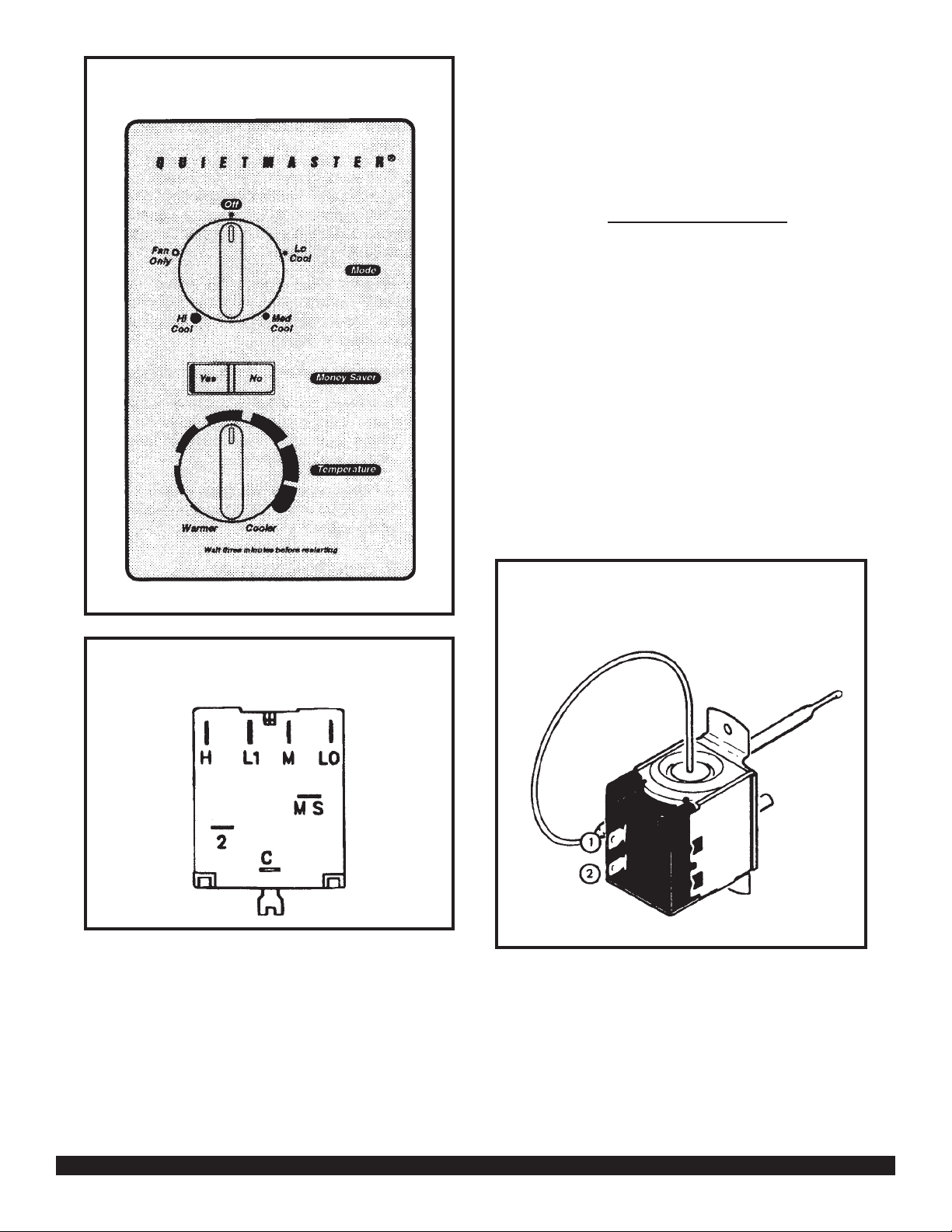
Figure 7: System Control Panel
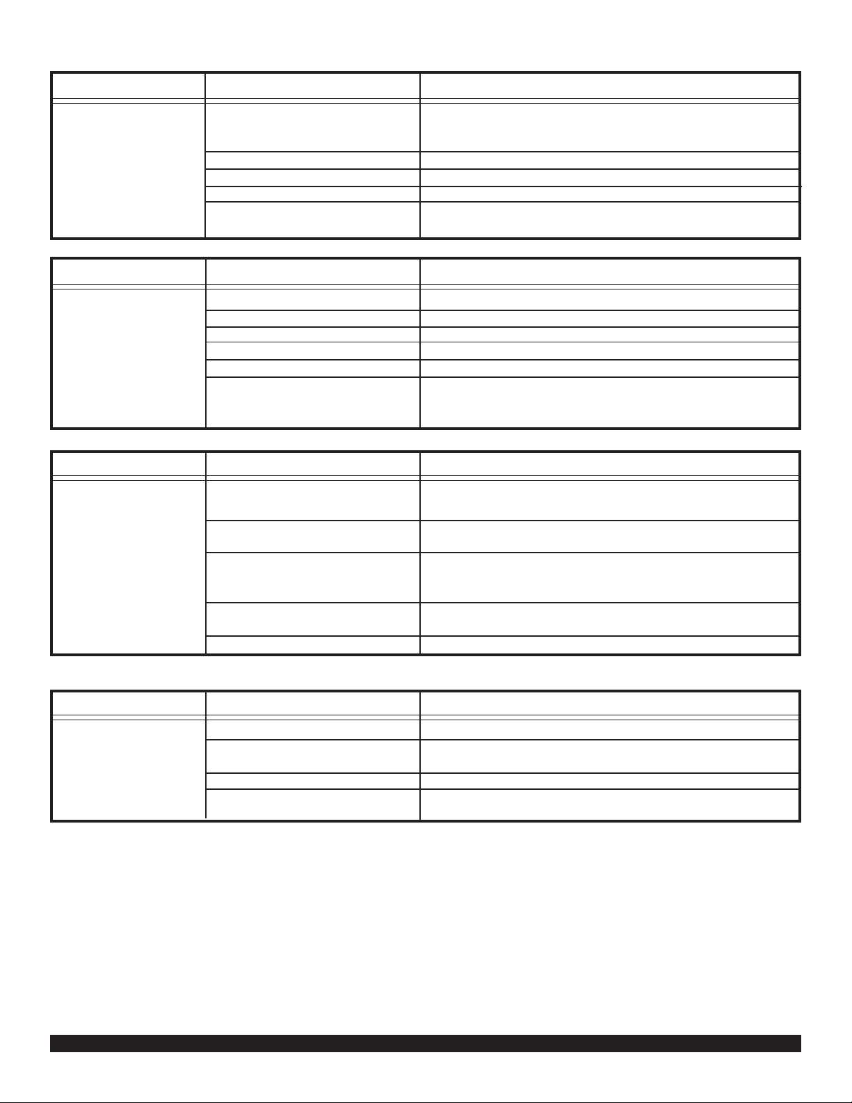
to supply a small amount of heat to the bulb area to
prevent long “off cycles” in the “Cool-Fan Auto” (Mone ySaver) position (see Figure 10.) A current feedback
through the fan motor windings during “off cycle” completes the circuit to the resistor.
RANGE: Cooling Model Thermostat
(Part No. 618-225-00)
60°F (± 2°) to 92°F (± 4°),
TEST:
Remove wires from thermostat. Turn the ther mostat to
its coldest position. Check to see if there is continuity
between the two terminals. Turn the ther mostat to its
warmest position. Chec k contin uity to see if thermostat
contacts open. NOTE: Temperature must be within range
listed to check thermostat. Refer to the troubleshooting
section in this manual for additional inf ormation on thermostat testing.
Figure 8: System Control Switch
THERMOSTAT
(Figure 9)
A cross ambient thermostat is used on all standard chassis units. In addition to cycling the unit in a heating or
cooling operation, the thermostat will terminate the cooling cycle in the event ice f orms on the evapor ator coil, in
this case the thermostat functions as a de-ice control.
A resistor (anticipator) is positioned within a plastic block
Figure 9: Thermostat
THERMOSTAT ADJUSTMENT
No attempt should be made to adjust thermostat. Due
to the sensitivity of the internal mechanism and the sophisticated equipment required to check the calibration,
it is suggested that the thermostat be replaced rather
than calibrated.
Page 11
Page 12

RESISTOR
(Heat Anticipator)
Failure of the resistor will cause prolonged “off” and “on”
cycles of the unit. When replacing a resistor, be sure
and use the exact replacement. Resistor r atings are as
follows:
115 Volt - 5,000 ohms 3 watt
230 Volt - 20,000 ohms 3 watt
Figure 10 RESISTOR
FIGURE 11 ROCKER SWITCH
MONEYSAVER® SWITCH
(Rocker Switch) - (See Figure 11)
This rocker switch can be depressed to either YES or
NO. In the YES position y ou will get the most economi-
cal operation. Both the fan and compressor will cycle on
and off together, maintaining the selected temperature
at a more constant level and reducing the humidity more
efficiently . This control will only operate when the unit is
in a cooling mode. In the NO position, the fan will run
constantly as long as the unit is in the cooling mode.
TEST:
Disconnect leads from switch. Depress switch to func-
tion being tested.
1. When YES is depressed, there should be continu-
ity between terminals “1” and “2”.
2. When NO is depressed, there should be continu-
ity between terminals “2” and “3”.
SEALED REFRIGERATION SYSTEM REP AIRS
EQUIPMENT REQUIRED
1. V oltmeter
2. Ammeter
3. Ohmmeter
4. E.P.A. Appro v ed Refrigerant Reco v ery System.
5. Vacuum Pump (capable of 200 microns or less
vacuum.)
6. Acetylene Welder
7. Electronic Halogen Leak Detector (G.E. Type H-6
or equivalent.)
8. Accurate refrigerant charge measuring device such
as:
Page 12
Page 13

a. Balance Scales - 1/2 oz. accuracy
b. Charging Board - 1/2 oz. accuracy
9. High Pressure Gauge - (0 - 400 lbs.)
10. Low Pressure Gauge - (30 - 150 lbs.)
11. Vacuum Gauge - (0 - 1000 microns)
EQUIPMENT MUST BE CAPABLE OF:
1. Recovering CFCs as low as 5%.
2. Evacuation from both the high side and low side of
the system simultaneously.
3. Introducing refrigerant charge into high side of the
system.
4. Accurately weighing the refrigerant charge actually
introduced into the system.
5. Facilities for flowing nitrogen through refrigeration
tubing during all brazing processes.
HERMETIC COMPONENT REPLACEMENT
7. Leak test complete system with electric halogen
leak detector, correcting an y leaks f ound.
8. Reduce the system to zero gauge pressure.
9. Connect vacuum pump to high side and low side
of system with deep vacuum hoses, or copper
tubing. (Do not use regular hoses .)
10. Evacuate system to maximum absolute holding
pressure of 200 microns or less. NOTE: This process can be speeded up by use of heat lamps, or
by breaking the vacuum with refrigerant or dry
nitrogen at 5,000 microns. Pressure system to 5
PSIG and leave in system a minim um of 10 minutes. Recover refrigerant, and proceed with e vacuation of a pressure of 200 microns or a minimum
of 10 %.
11. Break vacuum by charging system from the high
side with the correct amount of refrigerant specified. This will prev ent boiling the oil out of the crankcase.
NOTE: If the entire charge will not enter the high
side, allow the remainder to enter the low side in
small increments while operating the unit.
The following procedure applies when replacing components in the sealed refrigeration circuit or repairing refrigerant leaks. (Compressor , condenser , ev aporator , capillary tube, refrigerant leaks, etc.)
1. Recover the refrigerant from the system at the process tube located on the high side of the system by
installing a line tap on the process tube. Apply gauge
from process tube to EPA approved gauges from
process tube to EPA approved recovery system.
Recover CFCs in system to at least 5%.
2. Cut the process tube below pinch off on the suction side of the compressor.
3. Connect the line from the nitrogen tank to the suction process tube.
4. Drift dry nitrogen through the system and unsolder
the more distant connection first. (Filter drier, high
side process tube, etc.)
5. Replace inoperative component, and always install
a new filter drier. Drift dry nitrogen through the system when making these connections.
12. Restart unit sev eral times after allowing pressures
to stabilize. Pinch off process tubes, cut and solder the ends. Remove pinch off tool, and leak
check the process tube ends.
SPECIAL PROCEDURE IN THE CASE OF
MOTOR COMPRESSOR BURNOUT
1. Recover all refrigerant and oil from the system.
2. Remove compressor, capillary tube and filter drier
from the system.
3. Flush evaporator condenser and all connecting
tubing with dry nitrogen or equivalent, to remove
all contamination from system. Inspect suction and
discharge line for carbon deposits. Remove and
clean if necessary.
4. Reassemble the system, including new drier
strainer and capillary tube.
5. Proceed with processing as outlined under hermetic component replacement.
6. Pressurize system to 30 PSIG with proper refrigerant and boost refrigerant pressure to 150 PSIG with
dry nitrogen.
Page 13
Page 14

RO TARY COMPRESSOR SPECIAL
TROUBLESHOOTING AND SERVICE
Basically , troubleshooting and servicing rotary compressors is the same as on the reciprocating compressor
with only a few exceptions.
1. Because of the spinning motion of the rotary, the
mounts are critical. If vibration is present, check
the mounts carefully.
2. The electrical terminals on the rotary are in a different order than the reciprocating compressors.
The terminal markings are on the cover gasket.
Use your wiring diagram to insure correct connections.
REFRIGERANT CHARGE
1. The refrigerant charge is extremely critical. Measure charge carefully - as exact as possible to the
nameplate charge.
2. The correct method for charging the rotary is to
introduce liquid refrigerant into the high side of
the system with the unit off. Then start compressor and enter the balance of the charge, gas only ,
into the low side.
The introduction of liquid into the low side, without the use of a capillary tube, will cause damage
to the discharge valve of the rotary compressor.
NOTE: All inoperative compressors returned to
Friedrich must hav e all lines properly plugged with
the plugs from the replacement compressor.
Page 14
Page 15

Troubleshooting Cooling
PROBLEM POSSIBLE CAUSE TO CORRECT
Compressor does not
run.
Low voltage.
Thermostat not set cold
enough or inoperative.
Compressor hums but cuts off
on overload.
Open or shorted compressor
windings.
Open overload.
Open capacitor.
Inoperative system switch.
Broken, loose or incorrect
wiring.
Check for voltage at compressor. 1115 volt and 230 volt
units will operate at 10% voltage variance.
Set thermostat to coldest position. Test thermostat and
replace if inoperative.
Hard start compressor. Direct test compressor. If compressor starts, add starting components.
Check for continuity and resistance.
Test overload protector and replace if inoperative.
Test capacitor and replace if inoperative.
Test for continuity in all positions. Replace if inoperative.
Refer to appropriate wiring diagram to check wiring.
PROBLEM POSSIBLE CAUSE TO CORRECT
Test switch and replace if inoperative.
Refer to applicable wiring diagram.
Test capacitor and replace if inoperative.
Test switch and replace if inoperative.
Test fan motor and replace if inoperative (be sure internal
overload has had time to reset).
Fan motor does not
run.
Inoperative system switch.
Broken, loose or incorrect
wiring.
Open capacitor.
Fan speed switch open.
Inoperative fan motor.
PROBLEM POSSIBLE CAUSE TO CORRECT
Does not cool, or
cools only slightly.
Undersized unit.
Thermostat open or inoperative.
Dirty filter
Dirty or plugged condenser or
evaporator coil.
Pool air circulation in area
being cooled.
Fresh air or exhaust air door
open on applicable models.
Low capacity - undercharge.
Compressor not pumping
properly.
Refer to Sizing Charts.
Set to coldest position. Test thermostat and replace if
necessary.
Clean as recommended in the Owner's Manual.
Use steam or detergents to clean.
Adjust discharge air louvers. Use high fan speed.
Close doors. Instruct customer on use of this feature.
Clean for leak and make repair.
Check amperage draw against nameplate. If not conclusive, make pressure test.
Page 15
Page 16
PROBLEM POSSIBLE CAUSE TO CORRECT
Unit does not run.
Fuse blown or circuit tripped.
Power cord not plugged in.
System switch in "Off" position.
Inoperative system switch.
Loose or disconnected wiring at
switch or other components
Replace fuse, reset breaker. If repeats, check fuse or
breaker size. Check for shorts in unit wiring and components
Plug in power cord
Set switch correctly.
Test for continuity in each switch position.
Check wiring and connections. Reconnect per wiring
diagram.
PROBLEM POSSIBLE CAUSE TO CORRECT
Evaporator coil
freezes up.
Dirty filter.
Restricted air flow.
Inoperative thermostat.
Short of refrigerant.
Inoperative fan motor.
Partially restricted capillary.
Clean as recommended in Owener's Manual.
Check for dirty or obstructed coil - clean as required.
Test for shorted thermostat or stuck contacts.
De-ice coil and check for leak.
Test fan motor and replace if inoperative.
De-ice coil. Check temperature differential across coil.
Touch test coil return bends for same temperature. Test for
low running current.
PROBLEM POSSIBLE CAUSE TO CORRECT
Compressor runs
continually. Does not
cycle off.
Excessive heat load.
Restriction in line.
Refrigerant leak.
Thermostat contacts stuck.
Thermostat incorrectly wired.
Unit undersized. Test cooling performance of unit. Replace with larger unit.
Check for partially iced coil. Check temperature split
across coil.
Check for oil at silver soldered connections. Check for
partially iced coil. Check split across coil. Check for low
running amperage.
Check operation of thermostat. Replace if contacts remain
closed.
Refer to appropriate wiring diagram.
PROBLEM POSSIBLE CAUSE TO CORRECT
Thermostat does not
turn unit off.
Page 16
Thermostat contacts stuck.
Thermostat set at coldest point.
Incorrect wiring.
Unit undersized for area to be
cooled.
Replace thermostat.
Turn to higher temperature setting to see if unit
cycles off.
Refer to appropriate wiring diagram.
Refer to Sizing Chart.
Page 17

PROBLEM POSSIBLE CAUSE TO CORRECT
Compressor attempts
to start, or runs for
short periods only.
Cycles on overload.
Overload inoperative. Opens
too soon.
Compressor attempts to start
before system pressures are
equalized.
Low or fluctuating voltage.
Incorrect wiring.
Shorted or incorrect capacitor.
Restricted or low air flow through
condenser coil.
Compressor running abnormally
hot.
Check operation of unit. Replace overload if system
operation is satisfactory.
Allow a minimum of two (2) minutes for pressures to
equalize before attempting to restart. Instruct customer
of waiting period.
Check voltage with unit operating. Check for other
appliances on the circuit. The air conditioner should be
on a separate circuit for proper voltage, and be fused
separately.
Refer to appropriate wiring diagram.
Check by substituting a known good capacitor of correct
rating.
Check for proper fan speed or blocked condenser.
Check for kinked discharge line or restricted condenser.
Check amperage.
PROBLEM POSSIBLE CAUSE TO CORRECT
Thermostat does not
turn unit on.
Loss of charge in thermostat
bulb.
Loose or broken parts in thermostat.
Incorrect wiring.
Place jumper across thermostat terminals to check if unit
operates. If unit operates, replace the thermostat.
Check as above.
Refer to appropriate wiring diagram.
PROBLEM POSSIBLE CAUSE TO CORRECT
Noisy operation.
Poorly installed unit.
Fan blade striking chassis.
Compressor vibrating.
Improperly mounted or loose
cabinet parts.
Refer to Installation Instructions for proper installation.
Reposition - adjust motor mount.
Check that compressor grommets have not deteriorated.
Check that compressor mounting parts are not missing.
PROBLEM POSSIBLE CAUSE TO CORRECT
Water leaks into
room.
Evaporator drain pan overflowing.
Condensation forming on base
pan.
Poor installation resulting in rain
entering room.
Condensation on discharge
grilles.
Clean obstructed drain trough.
Evaporator drain pan broken or cracked. Reseal or replace.
Check installation instructions. Reseal as required.
Dirty evaporator coil - clean. Very high humidity level.
Page 17
Page 18

PROBLEM POSSIBLE CAUSE TO CORRECT
Thermostat short
cycles.
Thermostat differential too
narrow.
Plenum gasket not sealing,
allowing discharge air to short
cycle the thermostat.
Restricted coil or dirty filter.
Thermostat bulb touching
thermostat bulb support bracket.
Replace thermostat.
Check gasket, reposition or replace.
Clean and advise customer of periodic cleaning of filter.
Adjust bulb bracket.
(Applicable models.)
PROBLEM POSSIBLE CAUSE TO CORRECT
Prolonged off cycles
(automatic operation).
Anticipator (resistor) wire
disconnected at thermostat or
system switch.
Anticipator (resistor shorted or
open).
(Applicable models.)
Partial loss of charge in thermostat bulb causing a wide differential.
Refer to appropriate wiring diagram.
Replace thermostat block and resistor.
Replace thermostat.
PROBLEM POSSIBLE CAUSE TO CORRECT
Switches from cooling
to heating.
Thermostat sticking.
Incorrect wiring.
Change room thermostat.
Refer to appropriate wiring diagram.
PROBLEM POSSIBLE CAUSE TO CORRECT
Outside water leaks.
Evaporator drain pan cracked or
obstructed.
Water in compressor area.
Obstructed condenser coil.
Fan blade and slinger ring
improperly positioned.
Repair, clean or replace as required.
Detach shroud from pan and coil. Clean and remove old
sealer. Reseal, reinstall and check.
Steam clean.
Adjust fan blade 3/16 to 1/4" from condenser shroud.
Adjust fan motor mount to allow 3/16 to 1/4" clearance
between condenser fan blade and base pan.
PROBLEM POSSIBLE CAUSE TO CORRECT
High indoor humidity.
Insufficient air circulation in air
conditioned area.
Oversized unit.
Inadequate vapor barrier in
building structure, particularly
floors.
Adjust louvers for best possible air circulation.
Operate in "Fan-Auto (Moneysaver)" position.
Advise customer.
Page 18
Page 19

Page 19
Page 20

Page 20
Page 21

Page 21
Page 22

QUIETMASTER "KS" - "KM" SERIES PARTS LIST
REF. PART NO. DESCRIPTION APPLICATION
KKKK K
SSSMM
1111 2
0228 1
JJJJ J
1133 3
0000 0
ELECTRICAL PARTS AA
1 615-628-09 Compressor, Tecumseh, 115 V., 60 Hz., 1 Ph., Model RK5510E .................................. 1
1 615-628-00 Compressor, Tecumseh, 115 V., 60 Hz., 1 Ph., Model RK5512E .................................. 1
1 615-628-04 Compressor, Tecumseh, 115 V., 60 Hz., 1 Ph., Model RK5512EXD ............................. 1
1 617-187-01 Compressor, Bristol, 230/208 V., 60 Hz., 1 Ph., Model H23B175ABCC ....................... 1
1 611-935-46 Compressor, Tecumseh, 230/208 V., 60 Hz.,1 Ph., Model AWF5522EXN .................... 1
* 603-645-98 Overload, Compressor - MRA3790-114......................................................................... 1
* 603-645-90 Overload, Compressor - MRA4703-117......................................................................... 1
* 603-645-96 Overload, Compressor - MRA3794-114......................................................................... 1
* 615-780-10 Overload, Compressor - MRA98982-117....................................................................... 1
2 610-714-80 Motor, Fan ....................................................................................................................... 1
2 610-714-93 Motor, Fan ....................................................................................................................... 1
2 610-714-94 Motor, Fan ....................................................................................................................... 1
2 610-714-96 Motor, Fan ....................................................................................................................... 1 1
3 605-000-54 Cord, Electric Supply - 15 Amp., 125 Volt ...................................................................... 1
3 605-000-53 Cord, Electric Supply - 15 Amp., 125 Volt ...................................................................... 1
3 605-000-51 Cord, Electric Supply - 15 Amp., 250 Volt ...................................................................... 1 1
3 605-000-49 Cord, Electric Supply - 20 Amp., 250 Volt ...................................................................... 1
4 606-072-03 System Switch ................................................................................................................ 1 1 1 1 1
5 618-061-00 Rocker Switch ................................................................................................................. 1 1 1 1 1
6 618-225-00 Thermostat ...................................................................................................................... 1 1 1 1 1
7 610-803-38 Capacitor, Run - 25/10 MFD, 370 V................................................................................ 1 1
7 610-803-37 Capacitor, Run - 25/7.5 MFD, 370 V............................................................................... 1
7 610-803-34 Capacitor, Run - 35/7.5 MFD, 370 V............................................................................... 1 1
* 618-213-00 Harness Wire, Compressor ............................................................................................ 1 1 1
* 618-214-00 Harness Wire, Compressor ............................................................................................ 1
* 618-212-00 Harness Wire, Compressor ............................................................................................ 1
* 618-208-00 Harness Wire, Fan Motor................................................................................................ 1 1 1 1 1
8 618-080-00 Resistor Block - 115 V .................................................................................................... 1 1
8 618-080-01 Resistor Block - 230 V .................................................................................................... 1 1 1
Page 22
REFRIGERATION SYSTEM COMPONENTS
9 618-501-01 Coil, Evaporator .............................................................................................................. 1
9 618-501-00 Coil, Evaporator .............................................................................................................. 1
9 618-500-05 Coil, Evaporator .............................................................................................................. 1
9 618-500-02 Coil, Evaporator .............................................................................................................. 1 1
10 618-503-03 Coil, Condenser .............................................................................................................. 1 1 1
10 618-502-00 Coil, Condenser .............................................................................................................. 1 1
* 01390212 † Capillary Tube - .059 I.D. x 34" - 39" Long .................................................................. 1 1
* 03760520 † Capillary Tube - .059 I.D. x 31 5/8" - 35" Long ............................................................ 1
* 03760545 Capillary Tube - .042 I.D. x 20" Long ........................................................................... 3
* 03760479 Capillary Tube - .049 I.D. x 44" Long .............................................................................. 3
* 603-081-01 Filter - Drier (use when repairing sealed system) .......................................................... 1 1 1 1 1
CHASSIS PARTS
11 614-939-05 Knob, Control .................................................................................................................. 2 2 2 2 2
12 618-072-00 Panel, Control ................................................................................................................. 1 1 1
12 618-110-00 Panel, Control ................................................................................................................. 1 1
* 600-713-12 Bushing, Snap ................................................................................................................. 1 1 1 1 1
* Not Shown
Page 23

QUIETMASTER "KS" - "KM" SERIES PARTS LIST
REF. PART NO. DESCRIPTION APPLICATION
KKKKK
REFRIGERATION SYSTEM COMPONENTS (Cont.) SSSMM
11112
02281
JJJJJ
11333
00000
13 618-027-00 Panel Assembly, Left Side............................................................................................. 1 1 1
13 618-042-00 Panel Assembly, Left Side............................................................................................. 1 1
14 618-028-00 Partition, Control Box .................................................................................................... 1 1 1
14 618-043-00 Partition, Control Box .................................................................................................... 1 1
15 618-204-00 Bracket, Capacitor Mounting.........................................................................................11111
16 618-207-00 Strap, Capacitor................................................................................................... .......... 11111
17 618-226-00 Decorative Panel ........................................................................................................... 11111
1 * 618-076-00 Grommet, Suction Line .................................................................................................11111
* 618--148-00 Connector, Fresh Air & Exhaust .................................................................................... 1 1111
18 618-172-00 Cover, Top ...................................................................................................................... 11111
19 618-167-00 Insulation, Top Cover..................................................................................................... 11111
* 618-168-00 Insulation, Left Side Deck .............................................................................................11111
20 618-171-00 Deck............................................................................................................................... 11111
* 608-658-08 Filter, Air ........................................................................................................................ 1 1 1
* 608-658-09 Filter, Air ........................................................................................................................ 1 1
* 618-230-00 Holder, Filter .................................................................................................................. 22222
21 618-202-00 Air Foil............................................................................................................................ 11111
* 618-206-00 Bracket, Resistor Block ................................................................................................. 11111
* 915-003-01 Clamp, Supply Cord ...................................................................................................... 11111
22 605-420-03 Fan Blade ...................................................................................................................... 1 1 1
22 605-420-04 Fan Blade ...................................................................................................................... 1 1
23 606-106-03 Blower Wheel................................................................................................................. 1
23 606-106-01 Blower Wheel................................................................................................................. 1 1 1
23 606-106-05 Blower Wheel................................................................................................................. 1
24 618-033-00 Inner Wall....................................................................................................................... 1 1 1
24 618-047-00 Inner Wall....................................................................................................................... 1 1
25 618-025-00 Mount, Motor ....................................................................................................... .......... 1 1 1
25 618-041-00 Mount, Motor ....................................................................................................... .......... 1 1
26 618-036-00 Shroud ........................................................................................................................... 1 1 1
26 618-049-00 Shroud ........................................................................................................................... 1 1
27 618-026-00 Brace, Shroud................................................................................................................ 33333
28 618-169-00 Insulation, Inner Wall ..................................................................................................... 1 1 1
28 618-169-01 Insulation, Inner Wall ..................................................................................................... 1 1
29 618-173-00 Blower Front .................................................................................................................. 1 1 1
29 618-174-00 Blower Front .................................................................................................................. 1 1
30 618-149-00 Scroll ............................................................................................................. ................. 1 1 1
30 618-175-00 Scroll ............................................................................................................. ................. 1 1
31 618-215-00 Door Slide Assembly ..................................................................................................... 11111
32 618-034-05 Base Pan ....................................................................................................................... 1 1 1
32 618-034-18 Base Pan ....................................................................................................................... 1 1
32 618-034-01 Base Pan ....................................................................................................................... 1
* 618-038-00 Drain Pan....................................................................................................................... 1111
* 618-188-00 Rear Grille ..................................................................................................................... 1 1 1
* 618-188-01 Rear Grille ..................................................................................................................... 1 1
33 610-289-00 Grommet, Compressor ..................................................................................................3333
33 01150934 Grommet, Compressor .................................................................................................. 3
AA
* Not Shown † Capillary length may vary, flow rate is the same.
Page 23
Page 24

QUIETMASTER "KS" - "KM" SERIES PARTS LIST
REF. PART NO. DESCRIPTION APPLICATION
KKKKK
SSSMM
11112
02281
JJJJJ
11333
00000
AA
CHASSIS PARTS (Cont.)
34 914-004-00 Bolt, Compressor Mounting............................................................................................... 3 3 3 3 3
35 618-102-00 Plenum Assembly .............................................................................................................. 1 1 1 1 1
* 618-093-00 Knob, Fresh Air & Exhaust ................................................................................................ 1 1 1 1 1
* 618-092-00 Lever, Fresh Air & Exhaust................................................................................................ 1 1 1 1 1
* 618-062-00 Connector, Louver ............................................................................................................. 2 2 2 2 1
* 618-063-00 Louver, Grille ..................................................................................................................... 20 20 20 20 20
* 618-063-01 Louver, with Handle ........................................................................................................... 2 2 2 2 2
36 618-257-00 Outer Shell (with Sill Plate) ............................................................................................... 1 1 1
36 618-257-01 Outer Shell (with Sill Plate) ............................................................................................... 1 1
37 618-089-00 Grille, Intake ...................................................................................................................... 1 1 1
37 618-111-00 Grille, Intake ...................................................................................................................... 1 1
* 618-196-00 Guide, Shell ....................................................................................................................... 2 2 2 2
* 618-199-00 Latch, Intake Grille ............................................................................................................ 2 2 2 2 2
38 602-944-08 Wingboard ......................................................................................................................... 1 1 1
38 602-944-09 Wingboard ......................................................................................................................... 1 1
* 611-050-04 Accessory Package ........................................................................................................... 1 1 1
* 611-050-05 Accessory Package ........................................................................................................... 1 1
39 611-095-03 Bracket, Support................................................................................................................ 2 2 2 2 2
40 618-197-01 Angle, Wingboard (Top) ..................................................................................................... 1 1 1 1 1
41 618-198-01 Angle, Wingboard (Side) ................................................................................................... 2 2 2
41 618-198-03 Angle, Wingboard (Side) ................................................................................................... 2 2
42 606-103-03 Gasket (Vinyl) .................................................................................................................... 1 1 1 1 1
* 608-460-16 Plastic Bag (Hardware) ..................................................................................................... 1 1 1 1 1
* 617-173-01 Gasket, Chassis (Foam).................................................................................................... 1 1 1 1 1
* 618-116-03 Carton, Shipping................................................................................................................ 1 1 1 1
* 618-116-04 Carton, Shipping................................................................................................................ 1 1
* 618-139-00 Pad, Shipping .................................................................................................................... 1 1 1 1 1
* 618-118-00 Pad, Shipping .................................................................................................................... 2 2 2
* 618-118-01 Pad, Shipping .................................................................................................................... 2 2
* 618-141-01 Pad, Shipping (Top) ........................................................................................................... 1 1 1 1 1
43 600-733-00 Gasket, Window (Foam) .................................................................................................... 1 1 1 1 1
OPTIONAL ACCESSORIES
* 01900-235 Drain - Condensate Connection Kit, DC-2 ........................................................................ x x x x x
* 01900-312 Start Kit, Capacitor/Relay (Pow-R-Pak) ............................................................................ x x x xx
* Not Shown
Page 24
Page 25

Page 25
Page 26

Page 26
Page 27

QUIETMASTER "KL" SERIES PARTS LIST
REF. PART NO. DESCRIPTION APPLICATION
ELECTRICAL PARTS A
1 615-935-47 Compressor, Tecumseh, 230/208 V., 60 Hz., 1 Ph., Model AWR5524EXN ........................................ 1
2 610-714-85 Motor, Fan............................................................................................................................................. 1
3 605-000-49 Cord, Electric Supply - 20 Amp., 250 Volt ............................................................................................ 1
4 606-072-03 System Switch...................................................................................................................................... 1
5 618-061-00 Rocker Switch ....................................................................................................................................... 1
6 618-225-00 Thermostat ........................................................................................................................................... 1
7 610-803-34 Capacitor, Run - 35/7.5 MFD, 370 V .................................................................................................... 1
* 618-211-00 Harness Wire, Compressor ............................................................................................................... ... 1
* 618-208-00 Harness Wire, Fan Motor ..................................................................................................................... 1
8 618-080-01 Resistor Block - 230 V.......................................................................................................................... 1
REFRIGERATION SYSTEM COMPONENTS
9 618-501-02 Coil, Evaporator.................................................................................................................................... 1
10 618-503-07 Coil, Condenser .................................................................................................................................... 1
* 03760548 † Capillary Tube - .054 I.D. X 37 1/4" - 40" Long ................................................................................. 3
* 614-831-00 Filter Drier (use when repairing sealed system) .................................................................................. 1
K
L
2
5
J
3
0
CHASSIS PARTS
11 614-939-05 Knob, Control........................................................................................................................................ 2
12 618-069-00 Panel, Control ....................................................................................................................................... 1
* 600-713-12 Bushing, Snap ...................................................................................................................................... 1
13 618-068-00 Panel, Left Side .................................................................................................................................... 1
* 618-176-00 Insulation, Left Side............................................................................................... ............................... 1
14 618-070-00 Partition, Control Box ............................................................................................. .............................. 1
15 618-204-00 Bracket, Capacitor Mounting................................................................................................................ 1
16 618-207-00 Strap, Capacitor................................................................................................... ................................. 1
17 618-226-00 Decorative Panel .................................................................................................................................. 1
* 618-076-01 Grommet, Suction Line ............................................................................................... ......................... 1
* 618-148-01 Connector, Fresh Air & Exhaust ........................................................................................................... 1
18 618-179-00 Cover, Top ............................................................................................................................................. 1
19 618-182-00 Insulation, Top Cover............................................................................................................................ 1
* 618-183-00 Insulation, Left Side Deck .................................................................................................................... 1
20 618-180-00 Deck...................................................................................................................................................... 1
* 608-658-10 Filter, Air ............................................................................................................................................... 1
* 618-230-00 Holder, Filter ...................................................................................................... ................................... 2
21 618-202-01 Air Foil................................................................................................................................................... 1
* 618-206-00 Bracket, Resistor Block ........................................................................................................................ 1
* 915-003-01 Clamp, Supply Cord ............................................................................................................................. 1
22 605-420-01 Fan, Blade ............................................................................................................................................ 1
* Not Shown † Capillary length may vary, flow rate is the same.
Page 27
Page 28

QUIETMASTER "KL" SERIES PARTS LIST
REF. PART NO. DESCRIPTION APPLICATION
CHASSIS PARTS (Cont.) A
23 606-106-02 Blower Wheel........................................................................................................................... 1
24 618-066-00 Inner Wall............................................................................................................................................. 1
25 618-067-00 Mount, Motor ....................................................................................................................................... 1
26 618-077-00 Shroud ................................................................................................................................................. 1
27 618-100-00 Brace, Shroud...................................................................................................... ................................ 3
28 618-169-02 Insulation, Inner Wall ........................................................................................................................... 1
29 618-178-00 Blower Front ........................................................................................................................................ 1
30 618-181-00 Scroll .................................................................................................................................................... 1
31 618-215-00 Door, Slide Assembly ............................................................................................... ........................... 1
32 318-071-01 Base Pan ........................................................................................................... .................................. 1
* 618-074-00 Drain Pan............................................................................................................................................. 1
* 618-188-02 Grille, Rear ........................................................................................................ .................................. 1
33 01150934 Grommet, Compressor ........................................................................................................................ 3
34 914-004-00 Bolt, Compressor Mounting................................................................................................................. 3
35 618-105-00 Plenum Assembly .................................................................................................... ............................ 1
* 618-093-00 Knob, Fresh Air & Exhaust ........................................................................................... ....................... 1
* 618-096-00 Connector, Louver ............................................................................................................................... 2
* 618-097-00 Louver, Grille ...................................................................................................... ................................. 20
* 618-097-01 Louver, with Handle ................................................................................................. ............................ 2
* 618-092-00 Lever, Fresh Air & Exhaust.................................................................................................................. 1
36 618-257-02 Outer Shell (with Sill Plate) ................................................................................................................. 1
* 618-084-01 Sill Plate.......................................................................................................... ..................................... 1
37 618-104-00 Grille, Intake ........................................................................................................................................ 1
* 618-199-00 Latch, Intake Grille .............................................................................................................................. 2
38 602-944-10 Wingboard .......................................................................................................... ................................. 1
* 611-050-03 Accessory Package ................................................................................................... .......................... 1
39 611-095-03 Bracket, Support.................................................................................................................................. 2
40 618-197-03 Angle, Wingboard (Top) ....................................................................................................................... 1
41 618-198-05 Angle, Wingboard (Side) ............................................................................................ ......................... 2
42 606-103-03 Gasket (Vinyl) ...................................................................................................................................... 1
* 608-460-16 Plastic Bag (Hardware) ....................................................................................................................... 1
* 617-173-01 Gasket, Chassis (Foam).............................................................................................. ........................ 1
* 618-116-05 Carton, Shipping.................................................................................................................................. 1
* 618-140-00 Pad, Shipping (Bottom) ....................................................................................................................... 1
* 618-141-00 Pad, Shipping (Top) ............................................................................................................................. 1
* 618-118-02 Pad, Shipping (Front & Rear) .............................................................................................................. 2
* 618-196-00 Guide, Shell ........................................................................................................ ................................. 2
43 600-733-00 Gasket, Window (Foam) ...................................................................................................................... 1
K
L
2
5
J
3
0
OPTIONAL ACCESSORIES
* 01900-235 Drain - Condensate Connection Kit, DC-2 .......................................................................................... x
* 01900-312 Start Kit, Capacitor/Relay (Pow-R-Pak) .............................................................................................. x
Page 28
Page 29

Use Factor y
Certified Parts . . .
RAC-K (1/98)
Friedrich Air Conditioning Co.
4200 North Pan Am Expressway • P.O. Box 1540
San Antonio, Texas 78295-1540 • U.S.A.
Phone: (210) 357-4400
Fax: (210) 357-4480
Printed in U.S.A.
Page 29
 Loading...