

Page 1

Kuhl ® Series
Room Air Conditioners
Installation and Operation Manual
Q Chassis Models Using R-32 Refrigerant
Kühl
92000022_00
115-Volt:
THE EXPERTS IN ROOM AIR CONDITIONING
KCQ08B10A
Page 2

FRIEDRICH
AIR CONDITIONING CO.
SAN ANTONIO, TX
MODEL NUMBER
EQ08N11-A
SERIAL NUMBER
AALY00219
VOLTS
60 HZ/ 1PH
115
103 VOLT MIN.
COOLING:
BTU/HR
7500
EER
9.8
AMPS
6.9
HEATING:
BTU/HR
4000
EER
AMPS
11.2
MAX AMPS:
23.5 OZS.
DESIGN PRESSURES
600 PSIG HS
300 PSIG LS
U.S. PATENTS
D458, 229 S
5,634,346
IF CONNECTED TO
A FUSE PROTECTED
CIRCUIT, USE A 12 A
TIME DELAY FUSE
LISTED 183H
ROOM AIR
CONDITIONER
FRIEDRICH
AIR CONDITIONING CO.
SAN ANTONIO, TX
Assembled in Mexico
MODEL NUMBER
EQ08N11-A
SERIAL NUMBER
AALY00219
VOLTS
60 HZ/ 1PH
Model Nameplate Location
Register your Air Conditioner
Model information can be found on the name plate.
Please complete and mail the owner registration card furnished with this product, or register online at www.friedrich.
com.
For your future convenience, record the model information in
Section R, information for the owner.
A. IMPORTANT SAFETY AND GENERAL INFORMATION
A.1 Introduction ............................................................................. 3
A.2 • Safety Symbols ..................................................................... 3
A.3 • SAFETY WARNINGS
A.4 Unpacking Instructions .......................................................... 5
A.5 Importance of a Quality Installation ..................................... 6
A.6 Packing List ............................................................................. 7
B. SPECIFICATIONS
B.1 Product Data ............................................................................ 8
B.2 Model Identification Guide ..................................................... 8
B.3 Outdoor Use ............................................................................. 8
C. INSTALLATION OF THE UNIT
C.1 Pre-Installation Checkpoints ................................................. 9
C.2 Tools Required ........................................................................ 9
C.3. Choosing a Location .......................................................... 9
C.4 Window Installation ............................................................. 10
C.5 Thru-the Wall Installation .................................................... 13
C.6 Cord Routing Change ...........................................................16
C.7 Install Filter ........................................................................... 18
E. ELECTRICAL
E.1 Electrical Safety Information ......................................... 19
E.2 Testing the Power Cord .................................................19
J. STARTUP AND OPERATION
J.1 Final Inspection ..................................................................... 20
J.2 Airflow direction adjustment ............................................... 20
J.3 Control Panel Operation ....................................................... 21
J.4 Remote Control Operation ................................................... 35
J.5 Start-up...................................................................................35
L. WIFI
M. TROUBLESHOOTING
M.1. Troubleshooting Tips ...................................................... 36
P. Appendixes
P.1 Accessories and Options ................................................37
R . INFORMATION FOR THE OWNER
R.1 Room air conditioner unit performance test data sheet .... 38
R.2 Routine Maintenance ............................................................ 38
R.3 Warranty ................................................................................ 39
2
Page 3

A. IMPORTANT SAFETY AND GENERAL INFORMATION
SAFETY IS IMPORTANT
A.1 Introduction
This booklet contains the installation and operating instructions for your Air Conditioning unit. There are some precautions that should be taken
to ensure proper operation. Improper installation can result in unsatisfactory operation or dangerous conditions.
Read this booklet and any instructions packaged with separate equipment required to make up the system prior to installation. Give this booklet
to the owner and explain its provisions. The owner should retain this booklet for future reference.
A.2 • Safety Symbols
We have provided many important safety messages in this manual and on your appliance. Always read and obey all safety messages.
This is a safety Alert symbol. This symbol alerts you to potential hazards that can kill or hurt you and others.
All safety messages will tell you what the potential hazard is, tell you how to reduce the chance of injury, and tell you
what will happen if the instructions are not followed.
All safety messages will follow the safety alert symbol with the word “WARNING” or “CAUTION”. These words mean:
WARNING
CAUTION
NOTICE
Indicates a hazard which, if not avoided, can result in severe personal injury or death and damage to product or other
property.
Indicates a hazard which, if not avoided, can result in personal injury and damage to product or other property.
Indicates property damage can occur if instructions are not followed.
This symbol indicates that this appliance uses a flammable refrigerant. If the refrigerant is leaked and is exposed to an
external ignition source, there is a risk of fire.
This symbol indicates that the Operation Manual should be read carefully.
This symbol indicates that service personnel should be handling this equipment with reference to the installation manual.
This symbol indicates that information is available such as the Installation and Operation manual, or the Service Manual.
3
Page 4

A. IMPORTANT SAFETY AND GENERAL INFORMATION
A.3 • Safety Warnings
The manufacturer’s warranty does not cover any damage or defect to the air conditioner caused by the attachment
WARNING
or use of any components, accessories or devices (other than those authorized by the manufacturer) into, onto or in conjunction with the air
conditioner. You should be aware that the use of unauthorized components, accessories or devices may adversely affect the operation of the
air conditioner and may also endanger life and property. The manufacturer disclaims any responsibility for such loss or injury resulting from
the use of such unauthorized components, accessories or devices.
WARNING
capabilities, or lack of experience and knowledge, unless they have been given supervision or instruction concerning use of the appliance by
a person responsible for their safety.
Children should be supervised to ensure that they do not play with the appliance.
WARNING
Do not use above 2,000 meters(6,562 feet).
WARNING: Electrical Shock Hazard
Disconnect all power to the unit before starting maintenance. All electrical connections and wiring MUST be installed by a qualified
electrician and conform to the National Code and all local codes which have jurisdiction. Failure to do so can result in property
damage, severe electrical shock or death.
:
This appliance is not intended for use by persons (Including children) with reduced physical, sensory or mental
:
The maximum altitude for this appliance is 2,000 meters(6,562 feet).
:
WARNING: Read Installation Manual
Read this manual thoroughly prior to equipment installation or operation. It is the installer’s responsibility to properly apply
and install the equipment. Installation must be in conformance with the NFPA 70-2023 national electric code or current edition,
International Mechanic code 2021 or current edition, and any other local or national codes.
WARNING: Safety First
Do not remove, disable, or bypass this unit’s safety devices. Doing so may cause fire, injuries, or death.
WARNING: This Product uses R-32 Refrigerant
Do not use means to accelerate the defrosting process or to clean, other than those
recommended by the manufacturer.
The appliance shall be stored in a room without continuously operating ignition sources
(for example: open flames, an operating gas appliance or an operating electric heater.
Do not pierce or burn.
Be aware that refrigerants may not contain an odor.
WARNING: Refrigeration System under High pressure
Do not puncture, heat, expose to flame or incinerate. Only certified refrigeration technicians should service this
equipment. R32 systems operate at higher pressures than R22 equipment. Appropriate safe service and handling
practices must be used.
Refrigerant
Safety Group
A2L
CAUTION: Do Not Operate Equipment During Active Stages Of
Construction
To ensure proper operation, Friedrich requires that all equipment is not operated during active construction phases. This includes active stages
of completing framing, drywalling, spackling, sanding, painting, flooring, and moulding in the equipment’s designated conditioning space. The
use of this equipment during construction could result in premature failure of the components and/or system and is in violation of our standard
warranty guidelines. The operation of newly installed equipment during construction will accelerate the commencement and/or termination of
the warranty period.
Keep all air circulation and ventilation openings free from obstruction.
WARNING:
WARNING:
pulsation to the unit could result in damage to the refrigerant tubing.
4
The unit should not be in contact with any equipment that will transmit vibration to the unit. Any excessive vibration or
Page 5

A. IMPORTANT SAFETY AND GENERAL INFORMATION
A.4 Unpacking Instructions
STEP 1. Cut all 4 packing straps.
STEP 2. Slowly remove outer box, careful not to loosen decorative front.
STEP 3. Remove upper cover.
STEP 4. Remove 4 corner angles.
STEP 5. Remove base carton.
STEP 1
STRAPS x4
STEP 3
STEP 2
STEP 4
STEP 5
Figure A.4
5
Page 6

Upon receiving the unit, inspect it for any damage from shipment. Claims for damage, either shipping or concealed, should be filed immediately
for or detection of refrigerant leaks. A halide torch (or any other detector using a naked flame) shall not be used. The following leak detection
the case of FLAMMABLE REFRIGERANTS, the sensitivity may not be adequate, or may need re-calibration. (Detection equipment shall
A. IMPORTANT SAFETY AND GENERAL INFORMATION
A.5 Importance of a Quality Installation
Optimal system performance and longevity depend upon a quality and proper installation. Failure to properly install this unit could result in
undesirable operation and subsequent faults and potential failures.
Carefully follow all guidelines listed in the manual and industry best practices. Conform to all local code requirements. Contact your local
technical representative with any questions or concerns.
with the shipping company. IMPORTANT: Check the unit model number, Cooling size, electrical characteristics, and accessories to determine if
they are correct.
WARNING:
sharp edges, or any other adverse environmental effects. It is recommended that the cord is checked for any potential damage when filter
maintenance is performed. If the supply cord is damaged, it must be replaced by the manufacturer, its service agent or similarly qualified
persons in order to avoid a hazard.
WARNING:
install.
Contact a licenced repair person to perform a leak check on the unit.
WARNING:
methods are deemed acceptable for all refrigerant systems. Electronic leak detectors may be used to detect refrigerant leaks but, in
be calibrated in a refrigerant-free area.) Ensure that the detector is not a potential source of ignition and is suitable for the refrigerant used.
Leak detection equipment shall be set at a percentage of the LFL.
WARNING:
shall only be performed by trained service personnel. This includes:
Opening of any ventilated Any tubing or refrigerant circuit work
Opening of any sealed components
Enclosures beyond the hinged door for filter cleaning
Scan this QR code to be linked to the Friedrich professional support page
where you can locate the Service Manual.
Check the unit power cord and make sure the cord is protected from wear, corrosion, excessive pressure, vibration,
If the unit appears damaged,or if a refrigerant leak is suspected, do not
Under no circumstances shall potential sources of ignition be used in the searching
Service of this product (aside from filter maintenance)
6
Page 7

A. IMPORTANT SAFETY AND GENERAL INFORMATION
A.6 Packing List
A
C
E F G
Installation Hardware
ITEM
NO
A
Q KÜHL UNIT
B
Q SIDE CURTAINS (INCLUDES 8 PUSH PINS)
C
WINDOW SEAL GASKET
D
SHELL GASKET (ADHESIVE-BACK)
for replacement installations only
Carbon Filter
Remote Control
R1 Insulation Panel
DESCRIPTION QTY.
B
D
Installation Hardware
ITEM
NO
E
1
2
1
1
SCREW #8 x ½" (BLUE BAG)
F
SCREW #8 x 1 ¼" (GREY BAG)
SPARE PUSH PINS
G
DESCRIPTION QTY.
4
3
4
Figure A.6 (Packing List)
7
Page 8
B. SPECIFICATIONS
B.1 Product Data
The Kühl gives you a variety of options for control, programming, and scheduling
including wireless capabilities.
Wireless Programming and Control:
Friedrich Connect allows you to conveniently control, program, and monitor your air
conditioning unit remotely from a smartphone or computer.
Pre-Programmed Timer Options:
Your unit’s digital control comes equipped with a 24-hour timer.
24-Hour Timer
The 24-hour timer allows you to set 2 temperature changes at pre-set times or a
unit control panel.
Customizable Programming Options:
Customizable timers, with up to four temperature adjustments per day, can be set
using Friedrich Connect for one or multiple units.
See www.friedrich.com for complete details on Friedrich Connect.
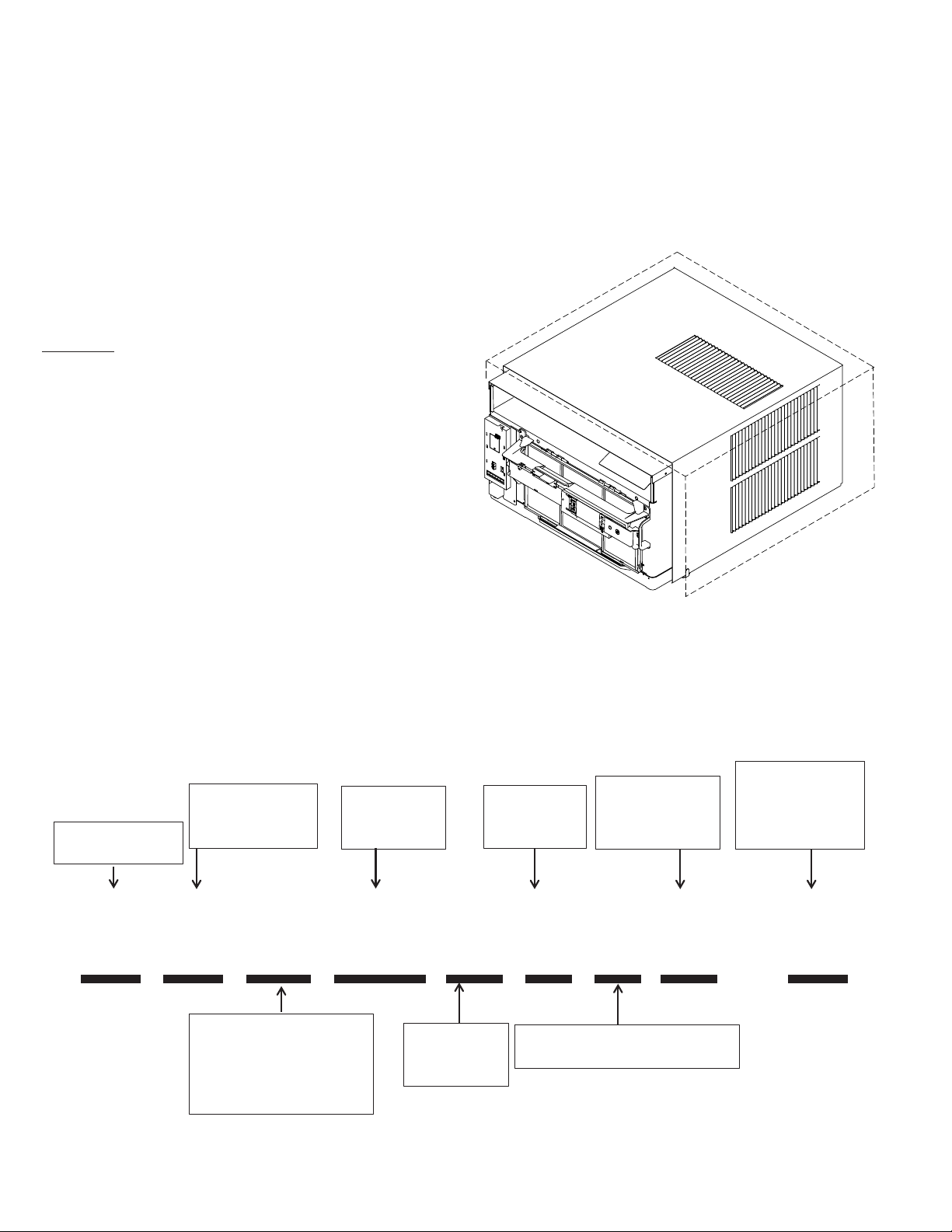
B.3 Outdoor Use
The only section of this air conditioner acceptable for outdoor use
is designated by the dotted area in the image below. To ensure the
protection of parts not acceptable for outdoor use please follow the
installation instructions as shown in this document. Please note that
junction and electrical boxes are not acceptable for outdoor use.
B.2 Model Identification Guide
Engineering Rev
Letter indicates an
engineering
modification to an
existing model
Model Type:
K - Kühl
Function:
C- Cool Only
H - Heat Pump
Approximate
Cooling
BTU/HR
Voltage
1- 115 Volts
3- 230 Volts
Marketing Suffix
Letter indicates
modification to
existing model
K H S 10 B 1 0 A - A
Application:
Q - Q
S - Small
M - Medium
L - Large
Major Model
Revision
Character
Heat Strip
0- Straight Cool & Heat Pump
8
Page 9

C. INSTALLATION OF THE UNIT
3
C.1 Pre-Installation Checkpoints
Before attempting any installation, carefully consider the
following points:
• Clearances and provision for servicing. Install this unit
in accordance with local and national standards. Any
and all work must be done by authorized personnel.
• IMPORTANT: Before you begin the actual installation
of your air conditioner, check your local electrical codes
and the information below. Your air conditioner must be
connected to a power source with the same alternating
current (A.C.) voltage and amperage as marked on the
name plate located on the chassis. Only A.C. can be used.
Direct Current (D.C.) cannot be used.
• CIRCUIT PROTECTION – Use on single outlet circuit only.
An overloaded circuit will invariably cause malfunction or
failure of an air conditioner; therefore, it is necessary that
the electrical protection is adequate. Due to momentary
high current demand when the air conditioner starts,
use a “TIME DELAY” fuse or a HACR type circuit breaker.
Consult your dealer or power company if in doubt.
• Refer to the electrical name plate located on the air
conditioner chassis (see Table E.1 to determine the
correct fuse or circuit breaker amperage for your model.
• The power cord has a plug with a grounding prong and a
matching receptacle is required.
C.2 Tools Required
WARNING
C.3. Choosing a Location
Installation Clearances
Improper installation of the Air Conditioner can cause poor performance and premature wear of the unit.
Ensure that the KUHL unit is installed with proper clearances as
described below.
Ensure no obstructions or enclosures are within clearances limits to
allow for proper airflow.
Ensure no open flames, or surfaces that will exceed 1200 degrees
fahrenheit are within clearances limits.
WARNING
Refigeration System
Under High Pressure
Do not puncture, heat, expose to flame or
incinerate.
Only certified refrigeration technicians should
service this equipment.
R410A and R32 systems operate at higher
pressures than R22 equipment.
Appropriate safe service and handling
practices must be used.
Only use gauge sets designed for use with
R410A or R32.
Do not use standard R22 gauge sets..
Clearances
Top and Bottom of Unit - One (1) foot
Sides of Unit - One (1) foot
Front of Unit - Three (3) feet
Rear of Unit - Three (3) feet
1. Power Drill
5/32
2.
” Drill Bit
3. Gloves
4. Carpenters Level
5/16
5.
” Wrench
1/4
6.
” Wrench
7. #2 Phillips Screw
Driver
8. Putty Knife or (wood
stir stick)
9. 1/4” Nut Driver
Electrical Shock Hazard
Make sure your electrical receptacle has the
same configuration as your air conditioner’s
plug. If different, consult a Licensed Electrician.
Do not use plug adapters.
Do not use an extension cord.
Do not remove ground prong.
Always plug into a grounded 3 prong outlet.
Failure to follow these instructions can result in
death, fire, or electrical shock.
4
1
2
5/16
5/16
1/4
Figure C.2 (Tools)
CAUTION
Moving Parts Hazard
Do not operate unit out of sleeve
or with front grille removed.
Do not place hands in blower
or fan blade areas.
Failure to do so can result
in serious injury
CAUTION
1/4
65
87
Excessive Weight Hazard
Use two or more people when
installing your air conditioner.
Failure to do so can result in
back or other injury.
9
Page 10

C. INSTALLATION OF THE UNIT
C.4 Window Installation
STEP 3. Once both curtains have been installed, slide hands underneath the
WARNING
Falling Object Hazard
Not following Installation Instructions
for mounting your air conditioner can
result in property damage, injury, or
death.
STEP 1. Fold down the sides of the carton bottom tray (see Figure C.4.1).
unit to lift and carry to the window, as shown in Figure C.5.3. Obtain
assistance as needed.
Figure C.4.1
STEP 2. Install side curtains (B in parts list) on both sides of the unit. Press
in the attached push pins (4 on each side) to secure curtains to the
sleeve (Figure 54).
Figure C.4.2
WARNING
Fire Hazard
A2L refrigerant is classified as mildly
flammable. Do not install unit next open flame
sources, or surfaces that will exceed
1200 degrees fahrenheit.
CAUTION
Excessive Weight Hazard
Use two or more people when installing your
air conditioner.
Failure to do so can result in back or other
injury.
NOTICE
For YOUR security and safety, YOU must
provide a means of preventing the upper
part of the window from opening.
10
Page 11

C.4 Window Installation (Continued)
SECTION A-A
STEP 4 Pull unit from sleeve, using the side handles located on either side of
the decorative front. Obtain assistance as needed. Place unit out of
the way on a secure, at surface (Figure C.4.4).
STEP 5 Place the sleeve in window with the bottom support rail up
against the back edge of the window sill. Center and close
window sash onto upper support rail. The unit should be
level or slightly tilted outside. Slope should be approximately
3/8” or 1/4 bubble on a level.
NOTE: Depending on the type of window, install the appropriate
security lock as recommended by manufacturer.
STEP 6 Extend side curtains to fill window. Secure outer top corner of
each curtain (left and right) to window jamb and/ or window
sash using supplied screws. Two sizes of screws (E and F
in parts list) and 2 different screw hole locations have been
provided to accommodate varying window types (See Figure
C.4.5).
C. INSTALLATION OF THE UNIT
If you desire a more permanent installation, you can secure your
curtains using both screw holes and your unit sleeve directly to the
lower window stool using the instruction Step 7 shown next. If you
choose the standard installation already covered in Steps 1 – 6, then
you can proceed to Step 8.
NOTE: When removing unit from sleeve and carrying or handling unit,
obtain assistance or help as necessary to support unit from bottom
(basepan), maintaining clearance from all obstacles.
STEP 7 Secure sleeve to window stool through screw hole in the bottom center of sill channel using 1 supplied 1 ¼" screw (F in parts list) (see Fig. C.4.5 Detail A).
In Step 6, the window curtains were secured using 1 supplied screw per curtain (2 screws total). For a more permanent application, you may secure
each curtain with an additional screw through the remaining screw hole, insuring each window curtain is secured to window jamb and sash with 2 screws
each (4 screws total). Two sizes of screws (E and F in parts list) have been provided to accommodate varying window types (see Figure C.4.5).
NOTE: Securing the curtains using both screw hole locations may not work in certain window types. For those applications, use only 1 screw per curtain and install
the appropriate security lock as recommended by window manufacturer.
SHELL SUPPORT CHANNEL
Figure C.4.4
WINDOW SASH
SECURE CURTAINS THROUGH
REMAINING HOLES USING
EITHER 1/2" SCREWS (ITEM E:
BLUE BAG) OR 1 1/4" SCREWS
(ITEM F: GREY BAG).
SECURE SILL CHANNEL TO
WINDOW STOOL USING (1) 1 1/4"
SCREW (ITEM F: GREY BAG).
WINDOW STOOL
SILL
CHANNEL
Figure C.4.5
A
A
SLEEVE
11
Page 12

C. INSTALLATION OF THE UNIT
C.4 Window Installation (Continued)
STEP 8 Inspect unit prior to inserting back into sleeve. Manually rotate fan to
see that it turns freely. Make sure electrical cord is positioned in the
front of unit and out of the way when inserting it back into the sleeve.
Insert unit back into sleeve by positioning onto bottom rails of sleeve
and pushing back into place. Obtain assistance as needed (see
Figure C.4.6).
Figure C.4.6
STEP 10 Plug in unit.
Now that installation is complete, your unit is ready to operate! Simply plug in
the power cord and follow the operation steps outlined in this manual or your
QuickStart Guide.
CIRCUIT PROTECTION - If the air conditioner is circuit protected by
a fuse, use a “TIME DELAY” fuse or HACR type circuit breaker due to
momentary high current demand when your air conditioner is started.
Before operating your unit, verify the ampere rating of the time-delay
fuse or circuit breaker which protects your unit. The ampere rating of
the time-delay fuse or circuit breaker shall be 15 amps.
WARNING
Electrical Shock Hazard
Make sure your electrical receptacle has the
same conguration as your air conditioner’s
plug. If different, consult a Licensed Electrician.
Do not use plug adapters.
Do not use an extension cord.
Do not remove ground prong.
Always plug into a grounded 3 prong outlet.
Failure to follow these instructions can result
in death, re, or electrical shock.
CAUTION
Excessive Weight Hazard
Use two or more people when installing your
air conditioner.
Failure to do so can result in back or other
injury.
NOTE: WHEN REMOVING UNIT FROM SLEEVE AND CARRYING
OR HANDLING UNIT, OBTAIN ASSISTANCE OR HELP AS
NECESSARY TO SUPPORT UNIT FROM BOTTOM (BASEPAN),
MAINTAINING CLEARANCE FROM ALL OBSTACLES.
STEP 9. Cut the window seal gasket (C in parts list) to match the window width
and insert it between the window sashes as shown in Figure C.4.7.
EntryGard™ Security Lock
For additional safety, your unit is equipped with EntryGard™ protection, a feature
that helps prevents kick-in intrusions. To engage this feature, use 2 supplied 1/2"
screws (E in parts list) to secure decorative front cover to sleeve. See Figure
C.4.8 for screw hole locations.
12
Figure C.4.7
Figure C.4.8
Page 13

C. INSTALLATION OF THE UNIT
C.5 Thru-the Wall Installation
STEP 1. After removing the unit from shipping carton, slide chassis out of
sleeve. Hold the cabinet stationary. Then, use the hand grips on both
ends of the control unit support bracket to pull the chassis out of the
cabinet. (See gure C.5.1)
Figure C.5.1
WARNING
STEP 2. Remove shell channel from top of the sleeve (Figure C.5.2).
NOTE: Not applicable to heat pump models sold without quick mounting
sleeve.
Figure C.5.2
WARNING
Falling Object Hazard
Not following Installation Instructions
for mounting your air conditioner can
result in property damage, injury, or
death.
STEP 3. Layout - Cut and frame-in an opening in the desired wall area using
the illustration as a guide (Figure C.5.3).
STEP 4. Place the sleeve in the framed opening.
NOTE: Not applicable to heat pump models sold without qui ck mounting sleeve.
2" x 8" FRAME
FINISHED OPENING SIZE
Fire Hazard
A2L refrigerant is classified as mildly
flammable. Do not install unit next open flame
sources, or surfaces that will exceed
1200 degrees fahrenheit.
EXPANSION ANCHOR BOLT
MOLLY OR TOGGLE BOLT
CONCRETE BLOCK
CONSTRUCTION
FRAME CONSTRUCTION
Figure C.5.3
13
Page 14

C. INSTALLATION OF THE UNIT
C.5 Thru-the Wall Installation (Cont.)
STEP 5 Position the front edge to extend into the room 3/4" minimum at top
of sleeve and 1" minimum at bottom (Figure C.5.4).
STEP 6 Secure each side of the sleeve with supplied 1 ¼" screw
NOTE: Alternate fasteners which may be used for securing the unit sleeve
(F in parts list) or nails through the holes in the sides.
to a wall, including masonry walls, are not furnished (available at
local hardware stores).
FRONT EDGE OF LOUVERS
MUST ALWAYS BE OUTSIDE OF
EXTERIOR WALL SURFACE
3
/4" MINIMUM
SLEEVE FRONT
1" THICK LUMBER
1
1" MINIMUM
INSIDE WALL
EXTERIOR WALL
MAX. WALL THICKNESS
ALLOWED 8 1/2"
POSITION AND SECURE
SLEEVE DOWNWARD.
SLOPE OUTSIDE FOR
DRAINAGE.
/4" SLOPE DOWN.
1 1/2" SCREWS (F IN PARTS LIST) / 3 EA. SIDE
NAILS MAY BE USED IF DESIRED.
3
/4" MINIMUM FRONT
EDGE OF SLEEVE TO
INSIDE WALL SURFACE.
TRIM AROUND THE
SLEEVE WITH A
SUITABLE WOOD
MOULDING AND
FINISH TO SUIT.
CAULK ALL AROUND
SLEEVE ON OUTSIDE
TO INSURE A WEATHER
TIGHT SEAL.
STEP 7 Cut two pieces of standard 1" lumber (supplied by installer)
to the length and width required. Place in front and back of
bottom sill channel as shown in Figure C.5.4. Secure with
nails (supplied by installer).
STEP 8 Seal all holes in the sleeve with caulking compound (supplied
by installer).
MORTAR
Figure C.5.4
SOLID MASONRY
CONSTRUCTION
CAULK ALL SIDES
CABINET
NOTE: ELECTRICAL RECEPTACLE LOCATION
FROM POINT “X” MUST BE WITHIN A MAXIMUM
RADIUS OF 69" FOR 115V UNITS.
14
ELECTRICAL
RECEPTACLE
POINT “X”
Figure C.5.5
Page 15

C.5 Thru-the Wall Installation (Cont.)
C. INSTALLATION OF THE UNIT
STEP 9 Inspect unit prior to inserting back into sleeve. Manually rotate fan to
see that it turns freely. Make sure electrical cord is positioned in the
front of unit and out of the way when inserting it back into the sleeve.
Insert unit back into sleeve by positioning onto bottom rails of sleeve
and pushing back into place. Obtain assistance as needed (see
Figure C.5.6).
Figure C.5.6
STEP 10 Plug in unit.
Now that installation is complete, your unit is ready to operate! Simply plug in
the power cord and follow the operation steps outlined in this manual or your
QuickStart Guide.
EntryGard™ Security Lock
For additional safety, your unit is equipped with EntryGard™ protection, a feature
that helps prevents kick-in intrusions. To engage this feature, use 2 supplied 1/2"
screws (E in parts list) to secure decorative front cover to sleeve. See Figure
C.5.7 for screw hole locations.
WARNING
Falling Object Hazard
Not following Installation Instructions
for mounting your air conditioner can
result in property damage, injury, or
death.
CIRCUIT PROTECTION - If the air conditioner is circuit protected by
a fuse, use a "TIME DELAY” fuse or HACR type circuit breaker due to
momentary high current demand when your air conditioner is started.
Before operating your unit, verify the ampere rating of the time-delay
fuse or circuit breaker which protects your unit. The ampere rating of
the time-delay fuse or circuit breaker shall be 15 amps.
WARNING
Electrical Shock Hazard
Make sure your electrical receptacle has the
same conguration as your air conditioner’s
plug. If different, consult a Licensed Electrician.
Do not use plug adapters.
Do not use an extension cord.
Do not remove ground prong.
Always plug into a grounded 3 prong outlet.
Failure to follow these instructions can result
in death, re, or electrical shock.
Figure C.5.7
15
Page 16

C. INSTALLATION OF THE UNIT
C.6 Cord Routing Change
Unplug unit.
Your Kühl Q unit will come with the power cord already installed and
routed to the left side of the unit.
WARNING
For convenience and optimum appearance the direction of the power
cord can be changed from left to right by following the procedure
below. Select the exit location on the left or right based on proximity
to the power outlet.
STEP 1. Remove the decorative front cover.
A. Open the decorative front cover. (See figure C.6.1)
B. Locate and disconnect electronic control power cable
harness. (See figure C.6.1)
C. Remove 4 screws attaching decorative front cover.
Save to reinstall later. (See figure C.6.2)
D. Remove decorative front cover. Store in a safe place to reinstall
later.
Electrical Shock Hazard
Make sure your electrical receptacle has the
same configuration as your air conditioner’s
plug. If different, consult a Licensed Electrician.
Do not use plug adapters.
Do not use an extension cord.
Do not remove ground prong.
Always plug into a grounded 3 prong outlet.
Failure to follow these instructions can result in
death, fire, or electrical shock.
Disconnect Plug
16
Figure C.6.1
STEP 2. Route the cord along bottom inside of the unit (see Figures C.6.4 and
C.6.5), under the lower left mounting screw embossments and exit the
cord through right side c ord opening (see Figure C.6.4) of the decorative
front cover. Decorative front cover will keep cord in place.
STEP 3. Reinstall the 4 screws removed earlier to secure decorative front cover
with cord exit ing to the front bottom of the unit (4 screws retained from
Step 1).
Remove Screws
Figure C.6.2
Page 17

C.6 Cord Routing Change
FACTORY SETTING WITH
LEFT-SIDE CORD PLACEMENT
Figure C.6.3 Figure C.6.5
C. INSTALLATION OF THE UNIT
CLOSE UP OF
CORD UNDER
LEFT MOUNTING
SCREW
EMBOSSMENT
NEW CORD ALIGNMENT FOR ROUTING CORD
EXIT TO THE RIGHT OF UNIT
Figure C.6.4
17
Page 18

C. INSTALLATION OF THE UNIT
ALIGN HOLES WITH
PROTRUSION
C.7 Install Filter
STEP 1. Swing the door open and remove the lter by grasping the lter grip
STEP 2. Slide the lter grip out from the lter as shown in Figure C.7.3.
NOTE: Make sure the front frame with the mesh lter is facing you.
STEP 3. If you already have a carbon lter installed remove the dirty lter by
Figure C.7.1
A
TOP TAB
FRONT
FRAME WITH
STANDARD
MESH FILTER
Figure C.7.4
and pushing the lter holder upward and outward. (See Figure C.7.2)
laying the lter down and swinging open the front frame as shown in
Figure C.7.4. Clean the front frame by washing the dirt from the lter.
Use a mild soap solution if necessary. Allow lter to dry.
Figure C.7.2
FILTER GRIP
FILTER
HANDLE
STEP 4. (Optional) Place the new carbon lter on the top of the back lter
frame. The carbon lter has been cut to the correct dimension and
should t within the frame as shown in Figure C.7.5.
NOTE: The carbon lter is not a reusable lter, and needs to be replaced every
three months for optimum efciency.
STEP 5. Slide the lter handle back on to hold the frames together
and slide the assembly into the unit as per the instructions
on the door.
NOTE: The lter handle slides into the frame in only one direction. If the tab
in the frame stops the handle from sliding in, slide the handle from the
other direction. DO NOT FORCE THE HANDLE INTO THE FRAME.
18
Figure C.7.3
FILTER GRIP
Figure C.7.5
Page 19

E. ELECTRICAL
E.1 Electrical Safety Information
WARNING
Electrical Shock Hazard
Make sure your electrical receptacle has the
same configuration as your air conditioner’s
plug. If different, consult a Licensed Electrician.
Do not use plug adapters.
Do not use an extension cord.
Do not remove ground prong.
Always plug into a grounded 3 prong outlet.
Failure to follow these instructions can result in
death, fire, or electrical shock.
Make sure the wiring is adequate for your unit.
If you have fuses, they should be of the time delay type. Before you
install or relocate this unit, be sure that the amperage rating of the
circuit breaker or time delay fuse does not exceed the amp rating
listed in Table 1.
DO NOT use an extension cord.
The cord provided will carry the proper amount of electrical power
to the unit; an extension cord may not.
Make sure that the receptacle is compatible with the
air conditioner cord plug provided.
Proper grounding must be maintained at all times. Two prong
receptacles must be replaced with a grounded receptacle by a certified
electrician.
The grounded receptacle should meet all national and local codes
and ordinances. You must use the three prong plug furnished with
the air conditioner. Under no circumstances should you remove the
ground prong from the plug.
E.2 Testing the Power Cord
All Friedrich room air conditioners are shipped from the factory
with a Leakage Current Detection Interrupter (LCDI) equipped power
cord. The LCDI device on the end of the cord meets the UL and NEC
requirements for cord connected air conditioners.
To test your power supply cord:
1. Plug power supply cord into a grounded 3 prong outlet.
2. Press RESET (see Figure 1).
3. Press TEST, listen for click; the RESET button trips and pops out.
4. Press and release RESET (Listen for click; RESET button latches and
remains in). Check that the green LED light is on. The power cord is ready.
for use.
RESET
TEST
WARNING:
TEST BEFORE EACH USE.
TO TEST:
PRESS RESET BUTTON.
PLUG LCDI INTO POWER
RECEPTACLE.
PRESS TEST BUTTON, RESET
BUTTON SHOULD POP UP.
PRESS RESET BUTTON FOR USE.
DO NOT USE IF TEST IS FAILED.
GREEN LIGHT INDICATES
PROPER OPERATION
Table E.1
MODEL
KCQ08
CIRCUIT RATING
OR TIME DELAY
FUSE
AMP VOLT
15 125 5-15R
NEMA
REQUIRED
WALL
RECEPTACLE
NO.
Once plugged in, the unit will operate normally without the need to reset the
LCDI device. If the LCDI device fails to trip when tested or if the power supply
cord is damaged, it must be replaced with a new power supply cord from the
manufacturer.
NOTICE
Do not use the LCDI device as an ON/OFF switch.
Failure to adhere to this precaution may cause pre-
mature equipment malfunction.
19
Page 20

J. STARTUP AND OPERATION
J.1 Final Inspection
• Inspect and ensure that all components and accessories have been
installed properly and that they have not been damaged during the
installation progress.
• Check the condensate water drain(s) to ensure that they are
adequate for the removal of condensate water, and that they meet
the approval of the end user.
• Ensure that all installation instructions concerning clearances
around the unit have been adhered to. Check to ensure that the unit
air filter, indoor coil, and outdoor coil are free from any obstructions.
• Inspect the unit for any damage to the coils and tubing that could
cause a leak.
• Ensure that the circuit breaker(s) or fuse(s) and supply circuit wire
size have been sized correctly. If the unit was supplied with a power
supply cord, insure that it is stored properly.
• Ensure that the entire installation is in compliance with all applicable
national and local codes and ordinances having jurisdiction.
• Secure components and accessories, such as a decorative front
cover.
• Start the unit and check for proper operation of all components in
LEFT
AIRFLOW
LEVER
each mode of operation.
• Instruct the owner or operator of the units operation, and the
manufacturer’s Routine Maintenance.
NOTE: A log for recording the dates of maintenance and/ or service is
recommended.
J.2 Airflow direction adjustment
The airow path may be adjusted to distribute air independently from the left or right
side of the discharge opening. Each of the banks of louvers can be directed left,
right, up, or down in order to achieve the most optimum airow positioning.
To adjust airow direction, grab the lever in the center of the louver bank and move it
in the direction that you would like the air to be directed. Please note that it is normal
that airow may be stronger out of one side of the louvers than the other.
RIGHT
AIRFLOW
LEVER
20
Figure J.2.1
Page 21

J. STARTUP AND OPERATION
WI-FI OPERATING
- Clock (AM/PM)
FAN SPEED
Sets fan speed:
LOW, MED, HIGH,
OR MAX
(Actual settings are
model dependant)
FAN
Sets fan to either:
- Automatically cycle
- Continuously run
MODE
Cycles between
COOL, HEAT, FAN
ONLY or -AUTO(if equipped)
ON / OFF
J.3 Control Panel Operation
Power On – Press the button to turn on the air conditioner. The power button illuminates to indicate that the power is on. The backlight on the power switch will
automatically turn off after 20 seconds of inactivity.
Display – The display is a high efciency LCD with a built-in backlight. After 20 seconds of inactivity, the display switches off. Touching any button automatically changes
the display to full brightness.
There are three control push buttons on each side of the display.
Turns unit on/off
COOL HEAT FAN ONLY DISCONNECTED FROM
-AUTO Automatically switches
between cool & heat
POWER BOARD
CONTROL
LOCKED
STAT E
IR
RECEIVER
TEMPERATURE
UP
TEMPERATURE
DOWN
TIMER
shows on or off
FILTER
Check / clean
2 DIGIT DISPLAY
Shows Setting for:
- Set Point (Temperature)
Figure J.3.1
21
Page 22

J. STARTUP AND OPERATION
J.3 Control Panel Operation
SYSTEM - The MODE button allows you to sequentially select up to four modes
of operation:
AUTO Available on select models
COOL
HEAT Available on select models
FAN ONLY
AUTO FAN (No Cooling Demand)
When in AUTO mode, the fan only operates when the system has a demand to
cool or heat the room.
In the ON fan mode, the fan operates all the time. The system periodically cools
or heats the fan’s airow but the ow of air does not stop.
UP and DOWN Arrows - Pressing either an UP or DOWN button changes the
system’s setpoint (desired room temperature). These buttons are also used to
make system parameter changes later in this manual.
One press equals 1 degree of change in Fahrenheit mode. One press equals 0.5
degree change in Celsius mode.
TIMER
The timer can be engaged or disengaged from the control panel. This is done by
pressing or holding the UP and DOWN arrows simultaneously for three seconds.
OTHER FUNCTIONS
°F – °C Select
To switch from degrees Fahrenheit (F) to Celsius (C), press the MENU button
and enter the F-C sub-menu.
FAN SPEED - Depending on your model, the FAN SPEED button allows you to
toggle between three or four modes of operation: LOW, MEDIUM, HIGH and MAX.
Alerts
When the lter needs to be cleaned or replaced, the CHECK FILTER icon
displays.
The alert can be dismissed by pressing the FAN MODE and SPEED for 3
seconds.
Lock Control Panel
To lock/ unlock the front panel controls, navigate to the “LOCK” sub-menu found after clicking the MENU button. The lock requires a four digit pass code to lock/ unlock
the unit. This pass code will be required to enter the menu to unlock the unit. The
LOCK icon illuminates to indicate the locked status.
The LOCK icon disappears to indicate unlocked status.
External Control Status
The Wi-Fi icon illuminates to indicate that the system is receiving a Wi-Fi connection. The Wi-Fi icon also provides information about the signal strength.
ADVANCED FUNCTIONS
The functions mentioned in the following section may or may not be available depending on the air conditioner model.
Modify the TIMER Function
Navigate to the TIME menu to set the timer.
22
Page 23

J.3 Control Panel Operation
Accessing Sub-Menus
The MENU button accesses the sub-menu. See Figure J.3.3.
The arrow buttons navigate the 6 menu options See Figure J.3.4:
– LIM – LOCK
– TM – CnCT
– F-C – diAG
The RETURN button exits the menu. See Figure J.3.5.
Figure
J.3.3
J. STARTUP AND OPERATION
Figure
J.3.4
Figure
J.3.5
MENU RETURN
MENU
RETURN
MENU
RETURN
23
Page 24

J. STARTUP AND OPERATION
J.3 Control Panel Operation
Navigating Inside the Sub-Menus
The MENU button moves you forward through the sub-menu.
See Figure J.3.6.
The RETURN button moves you backward once inside the LIM and
TM menus. See Figure J.3.7.
Figure
J.3.6
Figure
J.3.7
MENU
MENU
RETURN
RETURN
24
Page 25

J.3 Control Panel Operation
The LIM Menu
This is the limit menu. See Figure J.3.8.
Upon entering the menu, the rst option will be to set the lower setpoint
limit using the arrow buttons. See Figure J.3.9.
Figure
J.3.8
Figure
J.3.9
J. STARTUP AND OPERATION
Then you can set the higher setpoint limit using the arrow buttons.
See Figure J.3.10.
Pressing the menu button completes the limit setting. See Figure J.3.11.
MENU RETURN
Figure
J.3.10
Figure
J.3.11
MENU RETURN
MENU RETURN
MENU
RETURN
25
Page 26

J. STARTUP AND OPERATION
J.3 Control Panel Operation
The TM Menu
This is the TM menu used to set a timer. See Figure J.3.12.
In the menu, you set the current time using the arrow buttons. See Figure J.3.13.
(Note: These two “set clock” steps will be skipped if the unit is already connected
to Wi-Fi.)
First, set the hour.
Figure
J.3.12
MENU RETURN
Figure
J.3.13
Using the button, you switch to the minutes and complete setting the
time. See Figure J.3.14.
You select your mode. Either cool, heat, or auto. Toggle these using the
arrow buttons. See Figure J.3.15. (Note: cooling-only models skip this
step.)
The process is the same for all three modes. Auto mode will be shown as
the example.
Figure
J.3.14
Figure
J.3.15
MENU RETURN
MENU RETURN
MENU
RETURN
26
Page 27

J.3 Control Panel Operation
The TM Menu continued
Auto mode selected. See Figure J.3.16.
Set the cool setpoint for your rst timer period using the arrow buttons.
The cooling mode timer only sets the cool setpoint. See Figure J.3.17.
Next, set the heat setpoint for your rst timer period. The heating mode
timer only sets the heat setpoint. See Figure J.3.18.
Figure
J.3.16
J. STARTUP AND OPERATION
Note: The auto mode timer sets both the cool and heat setpoint.
Set the time to start the rst timer period. See Figure J.3.19.
Figure
J.3.17
Figure
J.3.18
MENU
MENU
MENU
RETURN
RETURN
RETURN
Figure
J.3.19
MENU RETURN
27
Page 28

J. STARTUP AND OPERATION
J.3 Control Panel Operation
The TM Menu continued
Set the cool setpoint for the second scheduled timer. See Figure J.3.20.
Set the heat setpoint for the second timer.
Set the time to start the second timer period. See Figure J.3.21.
Press the button to complete the time timer setup.
See Figure J.3.22.
Figure
J.3.20
Figure
J.3.21
Figure
J.3.22
MENU
RETURN
MENU RETURN
MENU
RETURN
28
Page 29

J.3 Control Panel Operation
The F-C Menu
This menu is used to toggle between Fahrenheit and Celsius.
This is the Fahrenheit/ Celsius Menu. See Figure J.3.23
Using the arrow buttons on the right side switches it from Fahrenheit to
Celsius. See Figures J.3.24 and J.3.25.
Figure
J.3.23
J. STARTUP AND OPERATION
MENU RETURN
Figure
J.3.24
Figure
J.3.25
MENU RETURN
MENU RETURN
29
Page 30

J. STARTUP AND OPERATION
J.3 Control Panel Operation
The Lock Menu
This menu is used to lock the changing setting with a password.
This is LOCK on. See Figure J.3.28.
This is the Lock Menu. See Figure J.3.26.
The default is the off setting. Use the arrows to toggle between off and
on. See Figure J.3.27
Figure
J.3.26
MENU RETURN
Figure
J.3.27
Set the rst digit of the password using the arrow buttons. Use the button
to proceed to the next digit. See Figure J.3.29.
Figure
J.3.28
Figure
J.3.29
MENU RETURN
MENU RETURN
MENU RETURN
30
Page 31

J.3 Control Panel Operation
The Lock Menu continued
Set the second digit of the password using the same method.
See Figure J.3.30
J. STARTUP AND OPERATION
Set the fourth digit of the password using the same method.
See Figures J.3.32
Set the third digit of the password using the same method.
See Figure J.3.31
Figure
J.3.30
Figure
J.3.31
Press the button to complete the password process.
See Figure J.3.33
MENU RETURN
Figure
J.3.32
Figure
J.3.33
MENU RETURN
MENU
RETURN
MENU RETURN
31
Page 32

J. STARTUP AND OPERATION
J.3 Control Panel Operation
The Lock Menu continued
The ON on the right side of the display shows the lock function is
active. To go back into the menu, select the button again.
See Figure J.3.34
Enter the password in the same manner it was created. See Figure
J.3.35.
Figure
J.3.34
Entering the correct password will give the user access to all of the submenus. See Figure J.3.36
Accessing the lock menu will allow you to toggle lock OFF if needed.
See Figure J.3.37
Figure
J.3.35
Figure
J.3.36
Figure
J.3.37
MENU
RETURN
MENU RETURN
MENU RETURN
32
MENU RETURN
Page 33

J.3 Control Panel Operation
The CnCT Menu
This menu is used to turn on Wi-Fi connection.
This is the CnCT menu. Pressing the button will activate Wi-Fi.
See Figure J.3.38
The Wi-Fi symbol in the top right corner of the display shows Wi-Fi
connection is on. See Figure J.3.39
Figure
J.3.38
J. STARTUP AND OPERATION
Figure
J.3.39
MENU RETURN
MENU RETURN
33
Page 34

J. STARTUP AND OPERATION
J.3 Control Panel Operation
The diAG Menu
This menu is used to access the diagnostic codes. See Figure J.3.40.
Selecting this sub-menu shows the E that represents “Error.”
See Figure J.3.41
Toggle through the error codes using the arrow keys. See Figure J.3.42
Figure
J.3.40
MENU RETURN
Figure
J.3.41
Figure
J.3.42
MENU RETURN
MENU RETURN
34
Page 35

J. STARTUP AND OPERATION
J.4 Remote Control Operation
Remote Control - Refer to Figure J.4.1 during operation description.
Getting Started - Install two (2) AAA batteries in the battery
compartment located on the back of the unit.
Operation - The remote control should be within 25 feet of the air
conditioner for operation. Press the power button to turn the remote on.
The remote will automatically power off after 15 seconds if the buttons
are not being pressed. The remote must be on to control the unit.
POWER Button - Turns remote and unit on and off.
SYSTEM Button - Allows the user to sequentially select the following:
AUTO, COOL, HEAT, and FAN ONLY operations. When the button is
pressed, the display indicates which mode has been selected via a
display message. Note that when the heating function is not available,
the system will automatically skip the HEAT mode.
FAN MODE Button - Selects between automatic (AUTO FAN) or
CONTINUOUS operation. In the AUTO FAN mode, the fan only turns on
and off when the compressor operates or the heat function is enabled.
NOTE: AUTO FAN is not available in the FAN ONLY Mode, the display
indicates CONTINUOUS. In the CONTINUOUS mode, fan speed is
determined by your selection on the FAN SPEED button.
FAN SPEED Button - Used to sequentially select new fan speed, plus
AUTO operation. When the FAN SPEED button is pressed, the fan
speed icon (triangle)
changes to indicate the new speed level. Fan speed automatically varies
depending on the set temperature on the control panel and the actual
room temperature. For example, if there is a big difference between
your set temperature and the actual room temperature, the system
fan speed increases to HIGH. It remains at this speed until the
room temperature matches the set temperature.
UP and DOWN Arrows - Pressing either the UP or DOWN button
changes the desired room temperature. The factory preset lower
and upper limits are 60 °F (16 °C) and 99 °F (37 °C). These buttons are
also used to navigate between function options when using the User
Menu or Maintenance Mode.
Remote Effectiveness
Handheld Remote - Has an operating range of up to 25 ft. The infrared
remote control signal must have a clear path to transmit the command to the air
conditioning unit. The remote signal has some ability to “bounce” off of walls and
furniture similar to a television remote control. The diagram below shows the typical
operating range of the control in a standard room with 8 ft high ceilings.
J.5 Start-up
This is a warm weather appliance
Your air conditioner is designed to cool in warm weather when the
outside temperature is above 60 °F (15.6 °C) and below 115 °F (46.1 °C),
so it won’t cool a room if it is already cool outside. If you want to cool a
room in the spring or fall, select the FAN ONLY mode and set the Fresh
Air/ Exhaust air control to Fresh Air. This will bring in a supply of cooler
outside air.
Condensation is normal
Air conditioners actually pump the heat and humidity from your room
to the outside. Humidity becomes water, and your air conditioner
will use most of the water to keep the outside coil cool. If there is
excessive humidity, there may be excess water that will drip outside.
This is normal operation.
Frosting
This usually occurs because of insufficient airflow across the coils, a
dirty filter, cool damp weather, or all these. Set the SYSTEM mode to
FAN ONLY and the frost will disappear. Setting the thermostat a little
warmer will probably prevent the frosting from recurring.
Noises
All air conditioners make some noise. Friedrich units are designed to
operate as quietly as possible. An air conditioner mounted in a wall is
quieter than one mounted in a window. It is important to ensure that
the chassis seal gasket (Item 13) is properly installed (refer to the
Installation Instructions).
NOTICE
This unit is certified to operate in cooling mode under these maximum conditions. Any operation beyond these conditions may result
in intermittent operation.
Indoor temperature: 90 °F (45% relative humidity)
Outdoor temperature: 110 °F (25% relative humidity)
If unit is heat pump equipped, it is certified to operate in heating
mode under these maximum conditions. Any operation beyond these
conditions may result in intermittent operation.
Indoor temperature: 80 °F (humidity does not affect operation)
Outdoor temperature: 70 °F (60% relative humidity)
L.
WiFi
MODE
FAN
SPEED
This model is currently compatible with Friedrich Connect and
Alexa, but not Google Connect. Use a QR Reader on your phone to
scan this QR Code. It will take you to the Wifi Instructions page of
our website.
POWER
UP and
DOWN
ARROWS
FIgure J.4.1
35
Page 36

M. TROUBLESHOOTING
M.1. Troubleshooting Tips
COMPLAINT CAUSE SOLUTION
• The unit is turned to the off position, or the
thermostat is satised.
• The LCDI power cord is unplugged.
Unit does not operate.
Unit Trips Circuit Breaker or
Blows Fuses.
LCDI Power Cord Trips
(Reset Button Pops Out).
Unit Does Not Cool/ Heat Room
Sufciently, or Cycles On And Off
Too Frequently.
• The LCDI power cord has tripped (Reset
button has popped out).
• The circuit breaker has tripped or the
supply circuit fuse has blown.
• There has been a local power failure.
• Other appliances are being used on the
same circuit.
• An extension cord is being used.
• The circuit breaker or time-delay fuse is
not of the proper rating.
• The LCDI power cord can trip (Reset
button pops out) due to disturbances on
your power supply line.
• Electrical overload, overheating, or cord
pinching can trip (Reset button pops out)
the LCDI power cord.
NOTE: A damaged power supply cord must be replaced with a new power supply cord obtained from the product manu-
facturer and must not be repaired. The power cord must be replaced by trained service personnel.
• The return/ discharge air grille is blocked.
• Windows or doors to the outside are open. • Ensure that all windows and doors are closed.
• The temperature is not set at a cool
enough/ warm enough setting.
• The lter is dirty or obstructed. • Clean the lter, (see Routine Maintenance), or remove obstruction.
• The indoor coil or outdoor coil is dirty or
obstructed.
• There is excessive heat or moisture
(cooking, showers, etc.) in the room.
• The temperature of the room you are
trying to cool is extremely hot.
• Turn the unit to the on position and raise or lower temperature
setting (as appropriate) to call for operation.
• Plug into a properly grounded 3 prong receptacle. See “Electrical
Rating Tables” on Page 6 for the proper receptacle type for your
unit.
• Press and release RESET (Listen for click. Reset button latches
and remains in.) to resume operation.
• Reset the circuit breaker, or replace the fuse as applicable. If
the problem continues, contact a licensed electrician.
• The unit will resume normal operation once power has been
restored.
• The unit requires a dedicated outlet circuit, not shared with other
appliances.
• Do NOT use an extension cord with this or any other air condition-
er.
• Replace with a circuit breaker or time-delay fuse of the proper rat-
ing. See “Electrical Rating Tables” on Page 6 for the proper circuit
breaker/ fuse rating for your unit. If the problem continues, contact
a licensed electrician.
• Press and release RESET (Listen for click. Reset button latches
and remains in.) to resume normal operation.
• Once the problem has been determined and corrected, press
and release RESET (Listen for click. Reset button latches
and remains in.) to resume normal operation.
• Ensure that the return and/ or discharge air paths are not blocked
by curtains, blinds, furniture, etc.
• Adjust the Temperature control to a cooler or warmer setting as
necessary.
• Clean the coils, (see Routine Maintenance), or remove obstruction.
• Be sure to use exhaust vent fans while cooking or bathing and,
if possible, try not to use heat producing appliances during the
hottest part of the day.
• Allow additional time for the air conditioner to cool off a very hot
room.
36
Page 37

M.1. Troubleshooting Tips (Cont)
COMPLAINT CAUSE SOLUTION
• The outside temperature is below 60 °F
(16 °C).
• The digital control is set to fan cycling mode.
Unit Does Not Cool/ Heat Room
Sufciently, or Cycles On And Off
Too Frequently (continued).
Unit Runs Too Much.
• The air conditioner has insufcient cooling
capacity to match the heat gain of the room.
• The air conditioner has insufcient heating
capacity to match the heat loss of the room.
• This may be due to an excessive heat load
in the room.
• It may also be due to an improperly sized unit.
• This may be normal for higher efciency
(EER) air conditioners.
• You may notice that the discharge air
temperature of your new air conditioner
may not seem as cold as you may be
accustomed to from older units. This
does not; however, indicate a reduction
in the cooling capacity of the unit.
M. TROUBLESHOOTING
• Do not try to operate your air conditioner in the cooling mode
when the outside temperature is below 60 °F (16 °C). The unit will
not cool properly, and the unit may be damaged.
• Since the fan does not circulate the room air continuously at this
setting, the room air does not mix as well and hot (or cold) spots
may result. Using the continuous fan setting is recommended to
obtain optimum comfort levels.
• Check the cooling capacity of your unit to ensure it is properly
sized for the room in which it is installed. Room air conditioners are
not designed to cool multiple rooms.
• Check the heating capacity of your unit. Air conditioners are sized to
meet the cooling load, and heater size is then selected to meet the
heating load. In extreme northern climates, room air conditioners may
not be able to be used as a primary source of heat.
• If there are heat producing appliances in use in the room, or if the
room is heavily occupied, the unit will need to run longer to remove
the additional heat.
• Be sure to use exhaust vent fans while cooking or bathing and,
if possible, try not to use heat producing appliances during the
hottest part of the day.
• The use of higher efciency components in your new air
conditioner may result in the unit running longer than you feel
it should. This may be more apparent, if it replaced an older,
less efcient, model. The actual energy usage, however, will be
signicantly less when compared to older models.
• The energy efciency ratio (EER) and cooling capacity rating
(Btu/ h) listed on the unit’s rating plate are both agency certied.
P. Appendixes
P.1 Accessories and Options
DC-2 Drain Kit – Part No. 01900235
In some installations, excess condensate water caused by extremely humid
conditions, may result in an undesirable water drip such as on a patio or over an
entryway. MODEL DC-2 DRAIN KIT (Part No. 01900-235) can be installed to drain
excess condensation to an alternate location.
Carbon Filter Kits
The kits vary depending on the chassis size (small, medium, large). Each kit contains
three (3) lters.
KWCFS – Carbon lter kit for small chassis models.
KWCFM – Carbon lter kit for medium chassis models.
KWCFL – Carbon lter kit for large chassis models.
Decorative Color Front Panel Kits
The kits vary depending on the chassis size (small, medium, large).
KWBGE(S/ M/ L)A – S/ M/ L Decorative Front Cover in Classic Beige
KWBLK(S/ M/ L)A – S/ M/ L Decorative Front Cover in Black Onyx
KWBLU(S/ M/ L)A – S/ M/ L Decorative Front Cover in Cobalt Blue
KWPNK(S/ M/ L)A – S/ M/ L Decorative Front Cover in Pink Diamond
KWRED(S/ M/ L)A – S/ M/ L Decorative Front Cover in Deep Red
KWWHT(S/ M/ L)A – S/ M/ L Decorative Front Cover in Designer White
Window Installation Kits (Standard in Kühl Models without
Heat)
KWIKS – For all KES and KHS models.
KWIKM – For all KEM and KHM models.
KWIKL – For all KEL and KHL models.
See www.friedrich.com for additional accessories for your unit.
37
Page 38

R . INFORMATION FOR THE OWNER
Present the owner or operator of the equipment with the
Installation & Operation Manual, all accessory installation
instructions, and the name, address, and telephone number of the
Authorized Friedrich Warranty Service Company in the area for
future reference if necessary. Inspect the unit for any damage to
the coils and tubing that could cause a leak.
R.1 Room air conditioner unit performance test
data sheet
Job name________________________________
Tech’s name______________________________
Date_________
Air Conditioned
Area
100 - 150 5000 550 - 700 14000
150 - 250 6000 700 - 1000 18000
250 - 300 7000 1000 - 1200 21000
300 - 350 8000 1200 - 1400 23000
350 - 400 9000 1400 - 1500 24000
400 - 450 10000 1500 - 2000 30000
450 - 550 12000 2000 - 2500 34000
Cooling BTUs
Required
Air Conditioned
Area
Cooling BTUs
Required
Model#____________________serial #_____________________
Check the installation acceptable not acceptable
Yes no
Is a chasis gasket installed? _____ ____
Is the fresh / exhaust air vent open? _____ ____
Is a friedrich sleeve installed? _____ ____
Is a friedrich outdoor grille installed? _____ ____
Is maintenance being performed? _____ ____
Electrical
Line voltage (static) _____ volts
Start up voltage _____ volts
Amperage draw (cool) _____ amps
Amperage draw (heat) _____ amps
Compressor
Locked rotor amps _____ amps
Running amperage draw _____ amps
Indoor conditions
Indoor ambient temperature _____ f
Relative humidity (rh) indoor _____%
Discharge air temperature (indoor)(cool) _____f
Discharge air temperature (indoor)(heat) _____f
Return air temperature (indoor)(cool) _____f
Return air temperature (indoor) (heat) _____f
Outdoor temperature
Outdoor ambient temperature _____f
Rh outdoor relative humidity _____%
Discharge air temperature (outdoor)(cool) _____f
Discharge air temperature (outdoor)(heat) _____f
Intake air temperature (outdoor)(cool) _____f
Intake air temperature (outdoor)(heat) _____f
Cooling or heating area
Area w______ * l_______ = feet squared
For a general guide refer to sizing guide to the right
For exact load calculations consult manual j or m.
R.2 Routine Maintenance
Decorative Front
Use a damp (not wet) cloth when cleaning the control area to prevent
water from entering the unit, and possibly damaging
the electronic control.
The decorative front and the cabinet can be cleaned
with warm water and a mild liquid detergent. Do NOT use solvents
or hydrocarbon based cleaners such as acetone, naphtha, gasoline,
benzene, etc.
The indoor coil can be vacuumed with a dusting attachment if it appears
to be dirty. DO NOT BEND FINS. The outdoor coil can be gently sprayed
with a garden hose.
Air Filter
The air filter should be inspected weekly and cleaned if needed by
vacuuming with a dust attachment or by cleaning in the sink using
warm water and a mild dishwashing detergent. Dry the filter thoroughly
before reinstalling. Use caution, the coil surface can be sharp.
WARNING: Service of this product (aside from filter
maintenance) shall only be performed by trained service personnel.
Refer to the Service Manual for procedures on how to inspect and
maintain the interior of the unit and its components. A QR code is located
in section A.5 which will help you locate the service manual online.
Coils & Chassis
The indoor coil and outdoor coils and base pan should be inspected
periodically (annually or semi-annually) and cleaned of all debris (lint,
dirt, leaves, paper, etc.) as necessary. Under extreme conditions, more
frequent cleaning may be required.
Wall Sleeve
Inspect the inside of the wall sleeve and drain system periodically
(annually or semi-annually) and clean as required. Under extreme
conditions, more frequent cleaning may be necessary.
Blower Wheel / Housing / Condensor Fan / Shroud
Inspect the indoor blower and its housing, evaporator blade, condenser
fan blade and condenser shroud periodically (yearly or bi-yearly) and
clean of all debris (lint, dirt, mold, fungus, etc.).
38
Page 39

R.3 Warranty
R. INFORMATION FOR THE OWNER
39
 Loading...