

Friedrich Hazardgard SH15, Hazardgard SH20, Hazardgard SH24 Installation & Operation Manual
Page 1

Hazardgard
®
Hazardous Location
Room Air Conditioner
Equipment is certied in accordance with:
ISA 12.12.01 and NFPA 70-10
(National Electric Code)
Article 501 ATE X*
Class I , Div. 2 Groups A,B,C,& D II 3 G Ex nA nC IIC T4 Gc
DEMKO 15 ATEX 1364X
Article 505 IECEx*
Class I , Zone 2, Groups IIA IIB + H and IIC Ex nA nC IIC T Gc IECEx UL15.0051X
8˚ C ≤ Tamb ≤ 55˚ C
240/220 V, 50 HZ :SH20*
230/208V : SH15, SH20
230/208V, 60 HZ ; 240/220V, 50 HZ : SH 24*
6/17 93031008_00
Installation & Operation Manual
Page 2

2
Table of Contents
Operation and Care Instructions
Your Safety and the safety of others ............................................................................................................................................ 2
General Instructions ..................................................................................................................................................................... 3
Filter Information .......................................................................................................................................................................... 4
Special Features .......................................................................................................................................................................... 5
Control Panel ................................................................................................................................................................................5
Underwriters Laboratories ........................................................................................................................................................... 6
Installation Instructions
Electrical Requirements ............................................................................................................................................................... 7
Installation Hardware ................................................................................................................................................................... 8
Unpacking the Unit .................................................................................................................................................................. 9 -10
Outdoor / Indoor Clearances.......................................................................................................................................................11
Through-the-Wall ...................................................................................................................................................................12-14
Sash Window ........................................................................................................................................................................15-20
Chassis Wiring and Preparation ........................................................................................................................................... 21-24
Chassis Installation ............................................................................................................................................................... 25-26
Maintenance Checklist ............................................................................................................................................................... 27
WARR ANT Y ............................................................................................................................................................................... 28
WARNING
ADVERTENCIA
AVERTISSEMENT
THINK
SAFETY
FIRST
To avoid the buildup Para evitar la acumulación de
o
f electrostatic charge, cargas electrostáticas, limpie
r
egularly clean the unit regularmente la unidad con un
with a damp cloth. paño húmedo.
Pour éviter l’accumulation de
c
harges électrostatiques,
ne
ttoyer régulièrement l’appareil
avec un chiffon humide.
Do not remove,
disable or bypass this
unit’s safety devices.
Doing so may cause,
fire, injuries or death.
No eliminar, desactivar o pasar
por alto los dispositivos
de seguridad de la unidad. Si
lo hace podria producirse
fuego, lesiones o muerte.
Ne pas supprimer, désactiver
ou contourner cette l’unité des
dispositifs de sécurité. Faire
vous risqueriez de provoquer,
le feu, les blessures ou la mort.
Do not open when an
explosive atmosphere
is presen
t.
No abra cuando se encuentre
en una atmósfera explosiva.
Ne pas ouvrir lorsque une
atmosphère explosive est
présente.
Do not separate
when energized.
No separar cuando se
encuentre bajo tensión.
Ne pas séparer sous
tension.
Page 3
3
Congratulations!
Thank you for your decision to purchase the Friedrich Hazardgard (Hazardous Duty Room Air Conditioner). Your new Friedrich has
been carefully engineered and manufactured to give you many years of dependable, efcient operation, maintaining a comfortable
temperature and humidity level. Many extra features have been built into your unit to assure quiet operation, the greatest
circulation of cool, dry air, and the most economic operation.
General Instructions
This Installation and Operation Manual has been designed to insure maximum satisfaction in the performance of your unit. For years of trouble-free
service, please follow the installation instructions closely. We cannot overemphasize the importance of proper installation. We have added new information to the basic instructions to help you achieve proper installation.
WARNING
Refrigeration system under high pressure.
Do not puncture, heat, expose to flame or incinerate.
Only certified refrigeration technicians should service
this equipment.
R410A systems operate at higher pressures than R22
equipment. Appropriate safe service and handling
practices must be used.
Only use gauge sets designed for use with R410A. Do
not use standard R22 gauge sets.
WARNING
Please read this manual thoroughly prior to equipment
installation or operation.
It is the installer’s responsibility to properly apply and
install the equipment. Installation must be in
conformance with the NFPA 70-2008 National Electric
Code or current edition, International Mechanic Code
2009 or current edition and any other applicable local
or national codes.
Failure to do so can result in property damage,
personal injury or death.
1. Carefully read and follow the installation instructions.
2. Make sure the unit is the right capacity for the area to be
cooled. An undersized unit makes the unit work too hard,
using more electricity than needed and increases wear. An
oversized unit will cycle on and off too rapidly, and therefore
cannot control humidity very well.
3. When you rst turn on your Friedrich, set the thermostat to
its coldest position to cool the room. When the desired temperature is reached, turn the thermostat control toward the
“warmer” position until you hear a click and the compressor
goes off. The thermostat will then cycle the compressor to
maintain the selected temperature.
4. Clean the lter frequently (See Filter Information)
5. Do not block the air ow to and from the unit. Make sure the
louvers are directed to give even distribution of air throughout the room. Caution: If air directed into a restricted area
such as a corner, this may cause the unit to cycle on and off
rapidly, which could damage your unit.
6. A dir ty lter or improperly set controls can affect the cool i n g
ability of the unit.
7. If cooling is weak and you have veried that the lter is
clean and the controls are properly set, the unit may be low
on refrigerant, and you should call your Friedrich service
provider to check the unit.
8. Keep blinds, shades and drapes closed on the sunny side of
the room being cooled.
9. Proper room insulation helps your unit maintain the desired
inside temperature.
10. Whenever possible, shade west-facing windows with awnings , trees, or window tinting.
11. Keep window treatments away from the unit to provide free
air ow.
Here are some suggestions to help you use your new Friedrich most efciently:
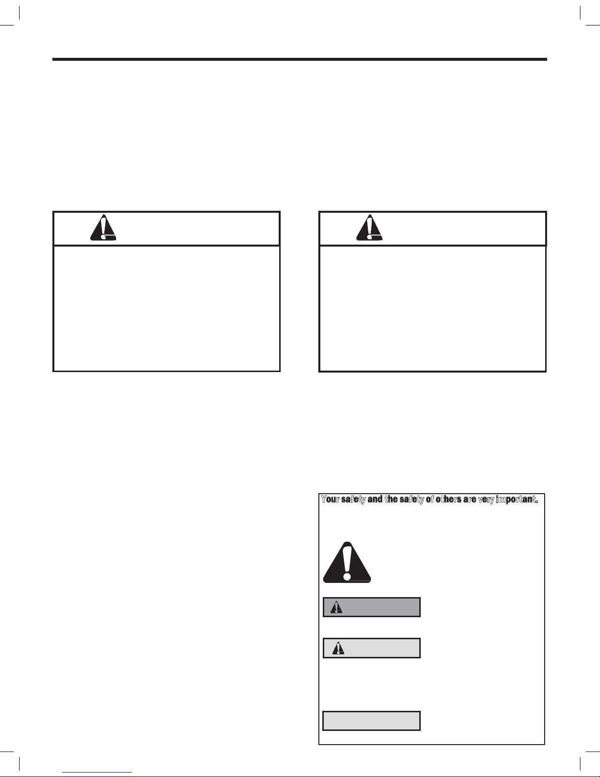
Your safety and the safety of others are very important.
We have provided many important safety messages in this manual
and on your appliance. Always read and obey all safety messages.
This is a safety Alert symbol. This symbol alerts you
to potential hazards that can kill or hurt you and
others.
All safety messages will follow the
safety alert
symbol with the word “WARNING” or “CAUTION”.
These words mean:
Indicates a hazard which, if not
avoided, can result in severe
personal injury or death and damage
to product or other property.
Indicates a hazard which, if not
avoided, can result in personal injury
and damage to product or other property.
All safety messages will tell you what the potential hazard is, tell you
how to reduce the chance of injury, and tell you what will happen if
the instructions are not followed.
Indicates property damage can
occur if instructions are not followed
WARNING
CAUTION
NOTICE
Page 4

4
Filter Information
The lter in your Friedrich removes dust, pollen and other impurities from the air as they are drawn through the unit. The lter is
permanent and reusable, and has a germicidal treatment which is not affected by periodic washing.
A clogged, dirty lter reduces the air ow through the unit and reduces its efciency. You should check the lter ever y seven to ten
days, depending on the amount your unit is used. Clean the lter regularly
Figure 1
FILTER
RETAINER CLIPS
The filter can be removed for cleaning by opening the front of
the unit and releasing the filter from its retaining clips.
Page 5

5
• Permanent Split-Capacitor, totally enclosed fan motor to
assure efcient operation even under adverse electrical
conditions.
• Motor has a special stainless steel shaft to resist corrosion
and a hermetically sealed overload for arc-free operation.
• High capacity compressor with internal hermetically sealed
overload.
• Contains transient voltage suppressor to protect controls
against transient voltage spikes. Provides solid state switches
for arc- free operation.
• Hot gas bypass low ambient control to permit operation without
freezing at outdoor ambient temperatures as low as 45°F (7°C).
• IP44 Environmentally sealed electrical components protect
against ingress of moisture ( ATEX & IECEx )
• Polyester powder nish, oven-baked for an attractive, long-
lasting nish
• Copper tubing/aluminum hydrophilic coated n coils
• Galvanized steel cabinet and base pan, all bonderized.
• Slide-out chassis for easy installation in window or through–
the–wall.
• Extra insulation inside, including completely insulated plenum
chamber for quieter, more efcient cooling.
• Entire unit test run in environmental chamber before crating.
• Eight-way air ow control for uniform circulation
• Condensate drain with exclusive mosquito trap.
• 15amp or 20amp circuit with time-delay fuse required.
Accommodates direct wiring.
• Long lasting 3/8” (10mm) thick air lter, germicidally treated,
easily removed for cleaning
Hazardgard Special Features
Control Panel
Function Control (Power)
This switch is a double pole, single throw toggle switch.
ON - Turns everything on.
OFF - Turns everything off.
WARNING
POWER MUST BE DISCONNECTED AT
CIRCUIT BREAKER/FUSE BEFORE SERVICING!
Temperature Control
The knob at the bottom is the thermostat which is a cross ambient type
used to maintain the desired comfort level. The thermostat reacts only to
a change in temperature at the bulb location - turn the knob clockwise to
set cooler, counter- clockwise for warmer.
Friedrich leads with the rst UL Listed Room Air Conditioners designed
to cool living quarters and other enclosures situated in hazardous loca-
tions where specic volatile ammable liquids or gases are handled or
used with enclosed containers or systems.
Friedrich Hazardgard room air conditioners are designed to meet the
National Electrical Code, Article 500 requirements for Class I, Division
2, Groups A,B,C,D Hazardous locations, CERTIFIED BY UNDERWRITERS
LABORATORIES FOR USE IN CLASS 1, DIVISION 2, GROUPS A,B,C,D
HAZARDOUS LOCATIONS.
Friedrich Air Conditioning quality has been proven by more than 30 years of successful experience from the Gulf of Mexico
to the searing sands of the Arabian Desert.
Page 6

6
SH20N50AT and SH24N20AT Adhere to the following certications:
CERTIFIED PER STD. NO. ANSI/ISA 12.12.01,2013
PER STD. NO. IEC 60079-0, 6th Edition PER STD. NO. IEC 60079-15, 4th Edition
PER STD. NO. CAN/CSA C22.2 NO. 213-M1987
PER STD. NO. CENELEC EN 60079-0: 2012 + A11: 2013
PER STD. NO. CENELEC EN 60079-15: 2010
CERTIFICATION DEMKO 15 ATEX 1364X II 3 G Ex nA nC IIC T4 Gc
IECEX UL15.0051X DEMKO 15 ATEX 1364X
SH20N50AT & SH24N20AT
Specic Conditions of Use:
• Provision shall be made to prevent the rated voltage being exceeded by
the transient disturbances of more than 140% of the peak rated voltage..
• The equipment must be installed only for use in locations providing
adequate protection against the entry of solid foreign objects or water
capable of impairing safety.
• Only permanently wired cables may enter the cable glands. The user
shall provide for the required strain relief.
• Degree of protection will be safeguarded only when sealing and cable
entry ttings are properlytted. The Manufacturer’s instructions must
be followed.
• Cable Glands shall be mounted into the enclosurein such a way that they
are mechanically protected against impact force.
• To avoid the buildup of electrostatic charge, regularly clean the unit with
a damp cloth.
• The appliance is not to be used by persons (including children) with
reduced physical, sensory or mental capabilities, or lack of experience
and knowledge, unless they have been given supervision or instruction.
Children to be supervised not to play with the appliance.
NOTICE: To maintain IP44 protection, the Hazardgard
unit must be installed in accordance to the installation
instructions stated in this document.
The following additional previous editions of Standards noted under
the “Standards” section of this Certicate where applied to integral
Components as itemized below. There are no signicant safety related
changes between these previous editions and the editions noted
under the “Standards” section.
Junction Box, Part No. 25. 10 16
08, manufactured by Rose.
IEC 60079-7:200607, IEC 60079-31:
ATEX & ICEX Standards Specic to Models SH20N50AT & SH24N20AT
Page 7

7
Installation Instructions
Models SH15, SH20 and SH24
NOTE: THIS MANUAL INCLUDES INSTALLATION INSTRUCTIONS FOR BOTH WINDOW MOUNT
AND THROUGH- THE WALL INSTALLATIONS
WARNING
Explosion Hazard
Electrical Shock Hazard
Electrically connect unit in accordance with NEC
Code Article 501. Failure to do so can result in
death, explosion, fire or electrical shock
Electrical Requirements
ALL FIELD WIRING MUST MEET THE REQUIREMENTS OF THE NATIONAL ELECTRICAL CODE (ANSI/NFPA
70) ARTICLE 501.
THE FIELD-PROVIDED CIRCUIT PROTECTION DEVICE (HACR CIRCUIT BREAKER OR TIME DELAY FUSE) MUST NOT EXCEED THE
AMPACITY INDICATED ON THE PRODUCT NAMEPLATE.
IMPORTANT: Before you begin the actual installation of your air conditioner, check local electrical codes and the information below.
Your power supply must be the same A.C. voltage and frequency (hertz) as marked on the name plate located on the chassis. Only
alternating current (A.C.), no direct current (D.C.), can be used.
An overloaded circuit will invariably cause malfunction or failure of the air conditioner; therefore, it is extremely important that the
electrical power is adequate. Consult your dealer or power company if in doubt.
The following instructions are for HAZARDGARD models and cabinet sizes listed below.
GROUPS CABINET SIZE (H x W X D)
SMALL CHASSIS SH15 15 15/16” x 25 15/16” x 27 3/8”
(405 mm x 660 mm x 695 mm)
MEDIUM CHASSIS SH20, SH 24 17 15/16” x 25 15/16” x 27 3/8”
(455 mm x 660 mm x 695 mm)
Model Number Plug Type Circuit Rating
Time Delay Fuse
SH15 Junction Box 250V-15 Amp
SH20, SH24 Junction Box 250V-15 Amp, 250V-20 Amp
Page 8

8
Window Mount Installation Hardware
ITEM
No.
DESCRIPTION QTY.
SHELL MOUNTING PARTS
1 SUPPORT BRACKET 2
2 SCREW, 10 - 24 x 1” HEX HEAD 4
3 10 - 24 FLAT WELDNUT 4
4 SCREW, SHEET METAL #12A x 2” 7
WINGBOARD ANGLE MOUNTING
5 WINGBOARD ANGLE, TOP 1
6 WINGBOARD ANGLE, SIDE 2
7 SCREW, SHEET METAL #8A x 3/8” 2
WINGBOARD MOUNTING PARTS
8 WINGBOARD (MASONITE) 1
9 J TYPE SPEED NUT 4
10 WINGBOARD CLIP (SPRING STEEL) 4
11 SCREW. #8A x 1/2” PHILLIPS TRUSS HD. 4
WINDOW SEALING
12 WINDOW SEAL GASKET (DARK FOAM) 1
ITEM #5 SEE ACCESSORY DETAIL IMAGE
ITEM #6 SEE ACCESSORY DETAIL IMAGE
ITEM # 12 SEE ACCESSORY DETAIL IMAGE
Page 9

9
Unpacking The Unit
STEP 1 Cut the packing straps and remove box pulling it up, remove corner-post and protective packing, conserve the berboard
wing board in a safe place, it will be used later.
Figure 2
Figure 3
Figure 4
STEP 2 Remove decorative plastic return air grille to a safe area away from the unit.
STEP 3 Remove the installation hardware, two gaskets from beneath the unit, and place them in a safe area away from the unit.
STEP 4 Remove the chassis retainer by removing the far right screw in the basepan (see Figure 4); save this screw to reattach the
chassis retainer after installation.
Page 10

10
Unpacking The Unit
Figure 5
Figure 6
Figure 7
STEP 5 Remove and discard the two retainer screws and plastic bushings located at the rear of the unit. (Figure 5)
STEP 6 While an assistant holds the cabinet stationary, use the hand pull at the front of the base pan (see Figure 6) to pull the chassis
out of the cabinet.
STEP 7 Remove white foam blocks used to restrain the compressor during shipment. Also remove junction box from under fan motor.
Page 11

11
Installation: Outdoor/Indoor Clearances
Figure 8
Figure 9
Page 12

12
Shell Installation: Through-the-wall Installations (as unit is shipped)
WARNING
Falling Object Hazard
Not following Installation Instructions
for mounting your air conditioner can
result in property damage, injury, or
death.
Wall Preparation
The maximum wall thickness permissible without special construction is determined by the model size to be installed. THE OUT- SIDE
CABINET CONDENSER AIR INTAKE LOUVERS MUST NOT BE BLOCKED BY EXTENDING INSIDE THE WALL
AREA. Observe the maximum wall thickness shown as dimension “A”in (Figure 10).
Special Instructions For Extra Thick Walls
For installation in walls exceeding the maximum thickness shown as dimension A, the following suggested construction may apply.
(See Figure 10).
Figure 10
EXTRA THICKWALL CONSTRUCTION
3.25" (82.55 MM)
MAXIMUM
WALL THICKNESS
CONDENSER
AIR INTAKE
LOUVERS
Top View
TOP VIEW SHOWING BEVELEDSIDES
FOR AIR
INTAKE a 45 deg angle
should
be maintained.
WALL BELOW
UNIT MUST ALSO BE BEVELED TO
ASSURE PROPER TILT ANGLE.
No louver should be
blocked. Maintain a
45 deg angle until
you clear the wall
CONDENSER AIR
INTAKE LOUVERS
STEP 1 CHECKING WIRING AND PLUMBING: Check all wiring and plumbing inside and outside the wall to be sure none will be broken
where the hole is to be cut.
STEP 2 HOLE CONSTRUCTION: Depending on the size of the unit to be installed, layout the hole dimensions in accordance with the
chart below (See Figure 11). Cut and frame in the hole to the nished dimensions. Use 2” x 4” material for framing and follow
the suggested typical installations in (Figure 12, 13 or 14 on Page 13.
NOTE: IF THE WALL CONSTRUCTION IS TYPICAL FRAME OR 2 X 4 STUDDING WITH BRICK OR STONE VENEERS, LOCATE THE HOLE
NEXT TO ONE OF THE STUDS. FOR MASONRY, CONCRETE OR CINDER BLOCK WALLS, LOCATE THE HOLE FOR CONVENIENCE.
Figure 11
HOLE SIZE REQUIREMENTS
NOTE: THESE DIMENSIONS ARE FOR FINISHED HOLE SIZE
FINISHED
DIMENSION
SH15
CHASSIS
SH20, SH24
CHASSIS
A 16-3/16” 18-3/16”
B 26-3/16” 26-3/16”
Page 13

13
CABINET
CAULK ALL
SIDES
INSIDE AND
OUTSIDE
SHIM TO FILL IN VOID AT
THE TOP AND SIDES WITH
WOOD AS REQUIRED
Figure 12 FRAME WALL CONSTRUCTION Figure 13 BRICK VENEER CONSTRUCTION
CAULK ALL
SIDES INSIDE
AND OUTSIDE
CABINET
SHIM TO FILL IN VOID AT
THE TOP AND SIDES WITH
WOOD AS REQUIRED
Figure 14 SOLID MASONRY CONSTRUCTION
MORTAR
CABINET
CAULK ALL
SIDES INSIDE
AND OUTSIDE
Page 14
14
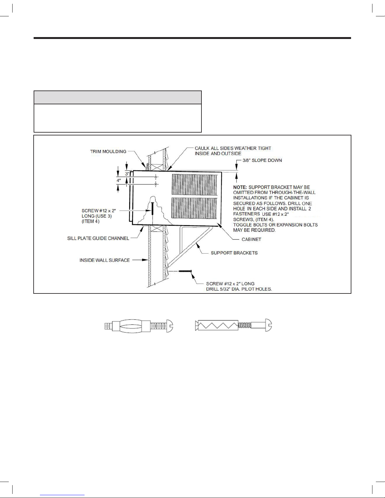
STEP 3 Slide the cabinet into the hole far enough to allow the guide-channel of the sill plate to contact the inside wall surface
(See Figure 15).
STEP 4 Drill three (3) 5/32” diameter pilot holes through holes in sill-plate into the framing and install three (3) #12 x 2” long screws
(Item #4) (See Figure15).
NOTICE
Instructions for mounting sleeve with slope must be observed to
prevent entry of water into room. Potential property damage can
occur if instructions are not followed.
NOTE: ALT E R N ATE FASTENERS WHICH MAY BE USED FO R SECURING TH E SILL PL ATE IN THE WA L L , AND TH E SUPPORT BR A C K E TS
TO THE OUTSIDE WALL ARE NOT FURNISHED, BUT ARE AVAIL ABLE AT A LOCAL HARDWARE STORE.
MOLLY OR TOGGLE BOLT EXPANSION ANCHOR BOLT
STEP 5 Drill two (2) 5/32” (4 mm) dia. pilot holes in each side at the locations shown (Figure 15) and install four (4) #12 x 2” screws
(Item #4). If the hole construction in Step 2 provides a sturdy mount with solid vertical studs, no support brackets are
required. The installation must support the weight of the unit plus an additional weight of 400 pounds (185 kg) on the rear of
the cabinet. The support brackets may be used for through-the-wall installations as shown in (Figure 15), for additional support.
STEP 6 If desired, trim around the cabinet on the room side with a suitable frame molding furnished by the installer (See Figure 15).
STEP 7 Skip to chassis wiring and preparation on page 21 for Non ATEX or page 23 for ATEX and IECEx.
Figure 15 TYPICAL INSTALLATION
Page 15

15
D E TA I L 16 - B
D E TA I L 16 - A
A
B
TOP ANGLE (ITEM #5)
CABNET
SILL PLATE TAB
SIDE ANGLE (ITEM #6)
2 REQUIRED
8-A X 3/8" LONG SCREW
(ITEM #7) 2 REQUIRED
TAB
TAB
LOOP
Shell (Cabinet) Preparation for Installation
STEP 1 Remove still plate and bend the taps up and reinstall. See (DETAIL 16-A).
STEP 2 Take the side angles (item #6) and engage its loops in the tabs (both sides) of the sill plate. (DETAIL 16-A).
STEP 3 Take the top Flange (item #5) and engage its tabs in the top loops of the side anges (DETAIL 16-B).
STEP 4 Install two (2) screws (Item #7) to secure the top angle tabs and the side angle in the side of the cabinet (Detail 16-B).
Figure 16
Page 16
16
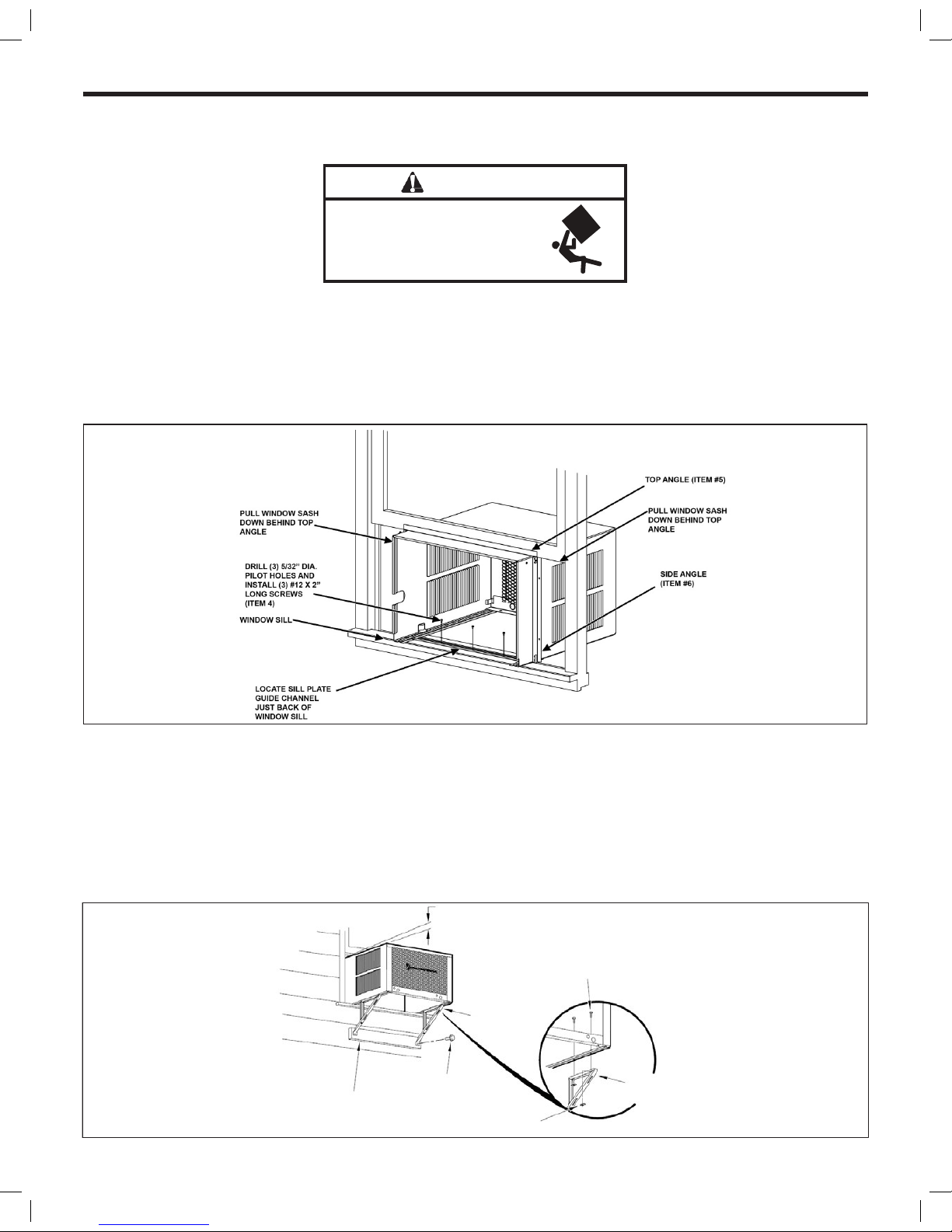
Shell Installation: Sash Window Installations
WARNING
Falling Object Hazard
Not following Installation Instructions
for mounting your air conditioner can
result in property damage, injury, or
death.
STEP 1 Check the window sill and frame to be sure they are in good condition and rmly anchored to the wall. Repair if necessar y.
STEP 2 CABIN E T MO UN T ING: Rai s e th e lower window sash 1/4” more than th e he ight of th e ca b inet. Carefull y sl ide the cabin e t through
the open window until the sill plate channel rests behind the window sill and the top support angle (Item #5) rests against the
window (See Figure 17). Center the cabinet side to side and drill three (3) 5/32” diameter pilot holes into the window sill using
the holes in the cabinet sill plate as a guide. Install three (3) #12A x 2” long screws (Item #4) (See Figure 17).
Figure 17
STEP 3 OUTSIDE SUPPORT MOUNTING: Assemble the suppor t brackets (Item #1) to the bottom rails of the cabinet with four (4) 10-24
1” long screws (Item #2) and four (4) 10–2 4 at nuts (Item #3). Adjus t the support br ackets to bring the bottom pads in contac t
with the wall surface. (See Figure 18.)
A 1” x 4” or 2” x 4” SPACER SHOULD BE USED BET WEEN THE WALL AND THE SUPPORT BRACKETS WHEN
INSTALLED ON ALUMINUM OR VINYL SIDING). Drill 5/32” (4 mm) diameter pilot holes, and secure the brackets to the wall
with two (2) #12A x 2” long screws (Item #4). Adjust the support brackets to provide an approximate 3/8” (10 mm) down slope
towards the outside for drainage. Tighten all screws. (See Figure 18).
Figure 18
3/8" (10 MM) DOWN SLOPE
10 - 24 X 1" HEX HEAD
SCREW (ITEM #2)
SUPPORT BRACKET
(ITEM 1)
A 1" X 4" OR 2" X 4" SPACER SHOULD BE USED BE-
TWEEN THE WALL AND BRACKET WHEN INSTALLED ON
ALUMINUM, ASBESTOS OR VINYL SIDING.
#12A X 2" SCREW
(ITEM#4)
SUPPORT BRACKET
(ITE M 1)
10 - 24 FLAT WELD
NUT (ITEM #3)
Page 17

17
Figure 19
The illustrations below show a standard frame construction
installation as well as some suggested ways of adapting the
support bracket to thick walls and large brick ledges.
NOTICE
Instructions for mounting sleeve with slope must be observed
to prevent entry of water into room.
Failure to follow instructions can result in property damage.
Figure20
Typical Installation: Sill Plate
Page 18

18
Typical Installation: Sill Plate (cont.)
Figure 21
Figure 22
Page 19

19
Figure 23
Figure 24
STEP 5 ASSEMBLE CLIPS TO WINGBOARD PANELS: Assemble “J” type speed nuts (Item #9) and spring steel clips (Item #10) to the
edges of the cut wingboard panels (See Figure 24).
STEP 4 CUT WINGBOARD PANELS: Measure and cut the wingboard panels from the supplied masonite (Item #8) to t the spaces
between the side window channels and the sides of the cabinet (See Figure 23).
NOTE: AFTER CUT TING PANELS, MAKE A TRIAL TEST TO SEE IF THEY FIT THE SPACE WITH ABOUT 1/8” CLEARANCE BEFORE
GOING TO STEP 5.
Page 20

20
Figure 25
SECTION A -A
TOP OF CABINET
WINDOW JAM
CLIP (ITEM10)
PLACE WINGBOARD PANEL IN
WINDOW JAM TO COMPRESS
THE
SPRINGS INSIDE THE
RUNNERS,
AND SWING THE PANEL INTO
PLACE
INDICATED BY THE DOTTED LINE.
STEP 6 INSTALL SIDE WINGBOARD PANELS: Be sure that the cabinet has been secured to the window sill and the outside support
br ackets have been installed as shown in (Figures 19 and 20) on Page 17. Raise the window sash and install the right and left
side wingboard panels (See Figure 25).
STEP 7 INSTALL WINDOW SEALING GASKETS: Measure and cut the dark foam window seal gasket (Item#12) and install it between
the upper glass panel and the top part of the lower sash (Figure 26).
Figure 26
NOTE FOR REASONS OF SECURITY , THE CUSTOMER MUST PROVIDE A MEANS OF PREVENTING THE WINDOW FROM OPENING.
STEP 8 When possible, caulk the outside of the installation with industrial type caulking to prevent air and water leaks.
STEP 9 Skip to chassis wiring and preparation on page 21 for Non ATEX or page 23 for ATEX and IECEx.
Page 21

21
Chassis Wiring and Preparation (Non ATEX)
PROVIDED HARDWARE
1 JUNCTION BOX
2 MOUNTING LEGS
2 LEG SCREWS
2 HOLE COVERS
1 STAINLESS STEEL
GROUND SCREW
2 SCREWS
1 SHEET METAL SCREW
Figure 27
Figure 28
STEP2 Remove and discard the threaded bushing wire protector from the conduit connector on the side panel of the control
compartment. Install eld supplied cable gland as required. Strip the wires approximately 1/2 inch (13 mm).
STEP1 Remove the junction box, cover and screws from the shipping position underneath the fan motor (See Figure 7). Install one
junction box mounting leg in the upper left position facing the rear of the junction box. (Figure 27)
Page 22

22
Figure 31
Chassis Wiring and Preparation
Figure 29
Figure 30
STEP 3 Insert all wires into the rear of the junction box and thread the box onto the threaded bushing until tight.
STEP 4 Back off clockwise until the junction box is vertical with the mounting leg at the upper–right position facing the box opening.
Be sure that the shell can slide between this box and the chassis.
STEP 5 Insert the unit in the shell see Page 25 for help, be sure that the shell can slide between junction box and the chassis.
NOTE: Field wiring conductors to be copper and a minimum of 12 AWG. Complete junction box wiring and cover to prevent
ingress from dust and moisture. All wiring connections to the junction box are to be made with cable glands.
Page 23

23
Figure 33
-FIELD CONNECTION-
EMI Filter
-AIR CONDITIONER-
Chassis Wiring and Preparation (ATEX & IECEx Models)
Figure 32
STEP 2 Proceed to make the STEP 1 of the Chassis Installation (see page 25 ) then come back to STEP 3
STEP 3 Insert air conditioner’s electric cable through provided cable gland on bottom of electrical junction box and tighten cable gland
nut (see Item 3) torque to 15 N-m, 106 in-lbs. Strip the three electrical conductors approximately 6.35 mm (1/4 inch) install
under provided terminal block LINE terminals and tighten (Item 4). Fixed eld wiring must include a eld provided disconnect
(all poles). Provide xed eld wiring conductors and cable gland with a minimum IP44 rating. Connect wiring conductors under
provided terminal block LOAD terminals and tighten (Item 5). Field conductors to be copper and a minimum 1.29 to 2.06 mm
(16 to 12 AWG). Ensure both LINE, LOAD and GROUNDs are adequately secured to provided termination points.
STEP1 Remove the junction box from the shipping position underneath the fan motor (Figure 7). Install junction box mounting legs
to back of the junction box using 4 provided machine screws (Figure 32-1). Mount junction box to provided holes on side of air
conditioner sleeve using 4 provided sheet metal screws and 4 serrated washers. Ensure serrated washers are between legs of
junction box and painted metal sleeve (gure 32-2).
To maintain IP44 protection and electrical safety, the Hazardgard unit must be installed in accordance to the
installation instructions provided with this product.
NOTE:
NOTE:
Notice: this air conditioner must be installed in accordance with national wiring regulations of country where
installed. Electrical connections to equipment must be carried out by qualified personnel per EN/IEC 6079-14.
Fixed wiring must include a field provided disconnect (all poles.) Repairs affecting hazard location protection
must be carried out by a qualified electrician in accordance with NEC/CEC 501.10 (B) and EN/IEC 60079-19.
Terminal block screw tightening torque .56N-m (5 in lbs) max. Wire size should be 1.29 to 2.06 mm (12 to
16AWG)
NOTE:
Page 24

24
Chassis Wiring and Preparation (ATEX & IECEx Models)
Figure 34
EXTERNAL GROUND
-See Note-
NOTE: This air conditioner shall be installed in accordance with national wiring regulations of the country where installed.
Electrical connections to equipment must only be carried out by qualied personnel per NEC/CEC 501.10 (B) EN/IEC 60079-14.
Repairs affecting hazard location protection must be carried out by a qualied electrician in accordance with NEC/CEC 501.10
(B) EN/IEC 60079-19.
STEP 4 Complete junction box wiring, cover and tighten cover screws (Figure 34-6) to prevent ingress from dust and moisture.
NOTE: Per EN/IEC 60079-0, external grounding or earthing may be necessary.
If required, use provided external ground clamp which can accept two cables of up to 6mm (Figure34-7).
INSTALLATION
ELECTRICAL JUNCTION
BOX
WITH EMI FILTER
Figure 35
Page 25

25
Chassis Installation
Figure 36
CHASSIS SEAL GASKET
CAUTION
Excessive Weight Hazard
Usetwo or more people when
installing your air conditioner.
Failure to do socan result in
backor other injury.
CAUTION
Cut/Sever
Although great care has been
taken to minimize sharp edges
in the construction of your unit,
use gloves or other hand
protection when handling unit.
Failure to do socan result in minor
to moderate personal injury.
WARNING
Explosion Hazard
Electrical Shock Hazard
Electrically connect unit in accordance with NEC
Code Article 501. Failure to do so can result in
death, explosion, fire, or electrical shock.
STEP1 Slide the chassis into the cabinet stopping approximately 3” from full insertion. Stuff the chassis seal gasket (Item
#12) one inch deep between the chassis and the cabinet (Figure 36). Begin at either bottom corner and go up the side, across
the top, and down the opposite side. Make sure that the gasket is behind the conduit connector (furthest from you). Push the
chassis into the shell the remaining distance so that the plastic front shrouds the front edge of the shell. Fasten the junction
box mounting foot to the shell with the sheet metal screw.
If chassis seal gasket is not installed, the operation of the unit will be negatively affected. Also, the operation noise and outside
noise will be amplied.
NOTE: Field wiring must be provided to this junction box in accordance with NATIONAL ELECTRIC CODE (NFPA 70, 2008 or current
edition) ARTICLE 501. Field and equipment grounds are to be terminated at the post in the junction box with the green screw
provided. Equipment power leads are to be connected with the eld supply by means of wire nuts (not provided). Install the
gasket and cover plate onto the junction box.
Page 26

26
End of Life
Customers are advised to ensure that the unit is disposed of in accordance with federal, state and local guidelines of their country.
Contact your municipal department of public works to inquire about the procedures for collecting and disposing of refrigerated appliances / air conditioners in your neighborhood.
Figure 37
Discharge Air Plenum
Slot
Tab
DETAIL 2
Slot
Tab
Return Air Grille
DETAIL 1
DETAIL 1
DETAIL 3
Latches
Latch
Return air grille
DETAIL 4
Side view
(Cutaway)
STEP 3 You have completed your installation. Conduct a review of your installation to insure that the unit is safely and
securely installed.
STEP 2 Be sure that the lter is in place then install the return air grille (Figure 37). The top of the return air grille can be butted
against the bottom of the discharge plenum. Snap the grille into place by pushing the grille up and onto the unit’s latches at
the bottom. (See Detail 37-4).
Page 27

27
Maintenance Checklist
Won’t Cool
If the unit operates, but doesn’t cool, check to see that the controls are properly set. Inspect the lter and if needed, clean it thoroughly.
Check to see if the chassis seal gasket is installed (refer to installation instructions).
Won’t Run
If the unit does not operate at all, check that the power supply connections are present and tight. Check for blown fuses or tripped circuit breakers. Replace blown fuses with the proper size time-delay fuse. The nameplate on the unit shows the proper fuse size. After
restoring power, wait three minutes before restarting the unit.
Inside Coil Freezes Up
Your Friedrich Hazardgard is designed not to freeze with outdoor temperatures as low as 45°F (7°C). Freezing should only occur when
the outside air is damp and below 45°F (7°C). If the indoor coil should ice over while cooling, set the thermostat to the warmest position
until the ice is gone. Setting the thermostat to a slightly warmer position will probably keep ice from forming on the coil. A dirty lter
will contribute to coil icing.
Cleaning
The front grille of your Friedrich, as well as the complete cabinet may be cleaned with warm water and a mild detergent. The coils and
base pan should be cleaned periodically for the most efcient operation. We suggest you call your Friedrich dealer for this service.
Lubrication
Fan motors are factory lubricated and sealed. No lubrication is required.
Page 28

28
Friedrich Air Conditioning Company
10001 Reunion Place, Suite 500
San Antonio, TX 78216
800.541.6645
www.friedrich.com
HAZARDGARD
®
ROOM AIR CONDITIONERS
LIMITED WARRANTY
LIMITED ONE YEAR PARTS WARRANTY
1. Limited warranty – One year. Friedrich warrants that it will provide a replacement for any part of this HazardGard Room Air
Conditioner found defective in material or workmanship for a period of one (1) year from the date of original purchase.
2. Limited warranty – One year. The Friedrich warranty also covers the cost of labor for repairing any compressor, condenser,
evaporator or inter-connecting tubing found defective within the warranty period, providing the unit is returned to an authorized
Friedrich Repair Station located within the Continental United States.
The Friedrich warranty does not cover:
(1) Any charges for removal, transportation or reinstallation of the unit; (2) the cost of labor to replace parts other than those
described above; and (3) does not apply to any HazardGard Room Air Conditioner that has been subject to (a) accident, misuse,
flood, fire, or neglect; (b) repairs or alterations outside of the Friedrich Authorized Dealer or Service Center so as to affect adversely
its performance and reliability; or (c) any repairs or servicing as a result of using parts not sold or approved by Friedrich.
LIMITATIONS: This warranty is a LIMITED warranty. Anything in the warranty notwithstanding, IMPLIED WARRANTIES
FOR PARTICULAR PURPOSE AND MERCHANTABILITY SHALL BE LIMITED TO THE DURATION OF THE EXPRESS
WARRANTY. MANUFACTURER EXPRESSLY DISCLAIMS AND EXCLUDES ANY LIABILITY FOR CONSEQUENTIAL OR
INCIDENTAL DAMAGES FOR BREACH OF ANY EXPRESSED OR IMPLIED WARRANTY.
Performance of Friedrich’s Warranty obligation is limited to one of the following methods:
1. Repair of the unit
2. A refund to the customer for the prorated value of the unit based upon the remaining warranty period of the unit.
3. Providing a replacement unit of equal value
The method of fulfillment of the warranty obligation is at the sole discretion of Friedrich Air Conditioning.
(11-10)
Page 29

29
Friedrich Air Conditioning Company
10001 Reunion Place, Suite 500
San Antonio, TX 78216
800.541.6645
www.friedrich.com
INTERNATIONAL
LIMITED WARRANTY
TERMS OF LIMITED WARRANTY
Friedrich Air Conditioning Co. warrants to the original purchaser that this Friedrich Air Conditioner is free from defects as to material
and workmanship.
This Warranty pertains to such manufacturing defects as may develop through normal usage and is in effect for a period of 12
months from date of installation or 18 months from the original date of purchase (date of invoice), whichever date shall occur first.
The Company’s obligation under this Warranty is limited to furnishing (FOB San Antonio, Texas – no freight allowed), at its option,
either a suitable replacement part or a remanufactured part or assembly for the sole purpose of replacing any part or parts which
may be defective. All such warranty claims shall be directed through an authorized Friedrich Distributor/Dealer. Friedrich reserves
the right to have the defective part returned to Friedrich for examination at the customer’s expense.
This Warranty does not apply to air filters, fuses, cabinet enclosures, refrigerant charge, and damage to any part resulting from
installation not in accordance with manufacturer’s recommendations; nor does it apply to exterior finishes, except where
examination discloses that same was defective at the time of initial shipment. This Warranty also does not apply to a Friedrich Air
Conditioner, or any part thereof, which has been subject to misuse, neglect, alteration, accident, flood, fire, or Act of God. No
warranty shall apply if the product has been used on electrical circuits of voltage and cycle characteristics other than specified on
the model and serial number plate.
GENERAL TERMS
The furnishing of replacement parts as described above shall constitute complete fulfillment of all obligations with respect to the
Friedrich Air Conditioner. Under no circumstances does Friedrich assume any responsibility for service, labor costs, or
transportation charges. THESE WARRANTIES ARE GIVEN IN LIEU OF ALL OTHER WARRANTIES, EXPRESS OR IMPLIED,
INCLUDING THE IMPLIED WARRANTIES OF MERCHANTABILITY OR FITNESS FOR A PARTICULAR PURPOSE.
(6-11)
Page 30

30
Friedrich Air Conditioning LLC
10001 Reunion Place, Suite 500
San Antonio, Texas 78216
800.5 41.6645
www.friedrich.com
Printed in Mexico 93031008_00
Page 31

Hazardgard
®
Unidad de aire acondicionado
para uso en lugares peligrosos
El equipo está certicado conforme a:
ISA12.12.01 y NFPA70-10
(National Electric Code)
Artículo 501 ATEX*
Clase I, División 2 Grupos A, B, C y D II 3 G Ex nA nC IIC T4 Gc
DEMKO 15 ATEX 1364X
Artículo 505 IECEx*
Clase I, Zona 2, Grupos IIA IIB + H y IIC Ex nA nC IIC T Gc IECEx UL15.0051X
8°C ≤ Tamb ≤ 55°C
240V-220V, 50Hz: SH20*
230V-208V: SH15, SH20
230V-208V, 60Hz ; 240V-220V, 50Hz: SH 24*
6/17 93031008_00
Manual de instalación y uso
Page 32

2
Índice
Instrucciones de uso y mantenimiento
Su seguridad y la de los demás ................................................................................................................................................... 2
Instrucciones generales ............................................................................................................................................................... 3
Información sobre el filtro ............................................................................................................................................................. 4
Características especiales............................................................................................................................................................ 5
Panel de control ........................................................................................................................................................................... 5
Underwriters Laboratories ............................................................................................................................................................ 6
Instrucciones de instalación
Requisitos eléctricos .................................................................................................................................................................... 7
Equipo de instalación ................................................................................................................................................................... 8
Desembalaje de la unidad .......................................................................................................................................................9-10
Espacios interiores y exteriores..................................................................................................................................................11
En la pared ............................................................................................................................................................................12-14
Bastidor de la ventana ..........................................................................................................................................................15-20
Cableado y preparación del chasis .......................................................................................................................................21-24
Instalación del chasis ............................................................................................................................................................25-26
Lista de control de mantenimiento ............................................................................................................................................. 27
GARANTÍA .................................................................................................................................................................................. 28
Table of Contents
Operation and Care Instructions
Your Safety and the safety of others ............................................................................................................................................ 2
General Instructions ..................................................................................................................................................................... 3
Filter Information .......................................................................................................................................................................... 4
Special Features .......................................................................................................................................................................... 5
Control Panel ................................................................................................................................................................................ 5
Underwriters Laboratories ........................................................................................................................................................... 6
Installation Instructions
Electrical Requirements ............................................................................................................................................................... 7
Installation Hardware ................................................................................................................................................................... 8
Unpacking the Unit .................................................................................................................................................................. 9-10
Outdoor / Indoor Clearances.......................................................................................................................................................11
Through-the-Wall ...................................................................................................................................................................12-14
Sash Window ........................................................................................................................................................................ 15 -20
Chassis Wiring and Preparation ........................................................................................................................................... 21-24
Chassis Installation ............................................................................................................................................................... 25-26
Maintenance Checklist ............................................................................................................................................................... 27
WARR ANT Y ............................................................................................................................................................................... 28
WARNING
ADVERTENCIA
AVERTISSEMENT
THINK
SAFETY
FIRST
To avoid the buildup Para evitar la acumulación de
o
f electrostatic charge, cargas electrostáticas, limpie
r
egularly clean the unit regularmente la unidad con un
with a damp cloth. paño húmedo.
Pour éviter l’accumulation de
c
harges électrostatiques,
ne
ttoyer régulièrement l’appareil
avec un chiffon humide.
Do not remove,
disable or bypass this
unit’s safety devices.
Doing so may cause,
fire, injuries or death.
No eliminar, desactivar o pasar
por alto los dispositivos
de seguridad de la unidad. Si
lo hace podria producirse
fuego, lesiones o muerte.
Ne pas supprimer, désactiver
ou contourner cette l’unité des
dispositifs de sécurité. Faire
vous risqueriez de provoquer,
le feu, les blessures ou la mort.
Do not open when an
explosive atmosphere
is presen
t.
No abra cuando se encuentre
en una atmósfera explosiva.
Ne pas ouvrir lorsque une
atmosphère explosive est
présente.
Do not separate
when energized.
No separar cuando se
encuentre bajo tensión.
Ne pas séparer sous
tension.
SEGURIDAD
ANTE TODO
LA
Ne pas supprimer désactiver
ou contourner les dispositifs
de sécurité de cet appareil.
Faire cela risque de causer un
incendie, des blessures ou un
décès.
Ne pas ouvrir lorsqu’une
atmosphère explosive est
présente.
Ne pas séparer sous
tension.
Pour éviter l’accumulation de
charges électrostatiques,
nettoyer régulièrement l’appareil
avec un chiffon humide.
No extraer, desactivar o eliminar
los dispositivos de seguridad de
la unidad ya que puede dar lugar
a incendios, lesiones o incluso la
muerte.
No abrir la unidad en presencia
de una atmósfera explosiva.
No mover la unidad cuando
está enchufada.
Para evitar la acumulación de
carga electrostática, limpiar con
frecuencia la unidad con un paño
húmedo.
Page 33

3
Felicitaciones
Gracias por la compra de la unidad de aire acondicionado Friedrich Hazardgard para uso en lugares peligrosos. Su nueva unidad Friedrich ha sido cuidadosamente diseñada y fabricada para brindarle muchos años de funcionamiento confiable y eficiente, a fin de mantener un nivel agradable de temperatura y humedad. Se han incorporado en la unidad muchas características adicionales para garantizar
un funcionamiento silencioso y económico con una mayor circulación de aire seco y fresco.
Instrucciones generales
Este manual de instalación y uso ha sido pensado para garantizar la máxima satisfacción en cuanto al rendimiento de la unidad. Para alcanzar
años de uso sin problemas, siga atentamente las instrucciones de instalación. No podemos dejar de destacar la impor tancia de una instalación
adecuada. Hemos añadido información nueva en las instrucciones básicas para que pueda realizar una instalación correcta.
WARNING
Refrigeration system under high pressure.
Do not puncture, heat, expose to flame or incinerate.
Only certified refrigeration technicians should service
this equipment.
R410A systems operate at higher pressures than R22
equipment. Appropriate safe service and handling
practices must be used.
Only use gauge sets designed for use with R410A. Do
not use standard R22 gauge sets.
WARNING
Please read this manual thoroughly prior to equipment
installation or operation.
It is the installer’s responsibility to properly apply and
install the equipment. Installation must be in
conformance with the NFPA 70-2008 National Electric
Code or current edition, International Mechanic Code
2009 or current edition and any other applicable local
or national codes.
Failure to do so can result in property damage,
personal injury or death.
1. Lea y siga atentamente las instrucciones de instalación.
2. Asegúrese de que la unidad tenga la capacidad adecuada para
el lugar que desea refrigerar. Si la capacidad es demasiado baja,
la unidad trabajará sobrexigida, consumirá más electricidad y se
desgastará más. Si la capacidad es demasiado alta, la unidad se
encender á y apagará muchas veces y no podrá, en consecuencia,
controlar muy bien la humedad.
3. Cuando encienda su unidad Friedrich por primera vez, coloque el
termostato en la temperatura más fría para refrigerar la habitación. Una v ez alcanzada l a temperatur a deseada, g ire el control del
termos tato hacia una tempe ratura más tem plada hasta e scuchar
un clic y que e l compresor se a paga. Luego, el t ermostato ha rá funcionar el compresor para mantener la temperatur a seleccionada.
4. Limpie el filtro con frecuencia (consulte el apartado “Información
sobre el filtro”).
5. No obstruy a el flujo de aire desde y hacia la unidad. Asegúrese de
que las rejillas estén dirigidas de tal forma que suministren una
distribución de aire uniforme en toda la habitación. Precaución:
Es posible que la unidad se dañe si el aire se dirige a una zona
restringida como una esquina ya que, en este caso, el equipo se
encenderá y apagará con rapidez una y otra vez.
6. Un filt ro sucio o el ajuste in correcto d e los controles p ueden afect ar
la capacidad de refrigeración de la unidad.
7. Si la refrigeración es deficiente y ha verificado que el filtro está
limpio, y que el ajuste de los controles es el correcto, es posible
que a la unidad le falte refrigerante y deba llamar a un prestador
de mantenimiento de Friedrich.
8. Mantenga las persianas y cortinas bajas en el lado soleado de la
habitación que debe refrigerarse.
9. La aislación adecuada de la habitación ayuda a la unidad a mantener la temperatura interior deseada.
10. De ser posible, utilice toldos, árboles o filtros para proteger del
sol a las ventanas que dan hacia el oeste.
11. Mantenga las persianas y las cortinas lejos de la unidad para que
el aire fluya sin problemas.
Algunas sugerencias para usar la nueva unidad Friedrich de manera más eficiente:
Sistema de refrigeración a alta presión
No perforar, calentar, exponer a las llamas o incinerar.
Solo los técnicos de refrigeración certificados pueden
realizar el mantenimiento de este equipo.
Los sistemas R410A funcionan a presiones más altas
que los equipos R22. Deben utilizarse prácticas de
mantenimiento y manipulación seguras y adecuadas.
Solo utilizar el conjunto de manómetros diseñado para
los sistemas R410A. No utilizar el conjunto de manómetros estándar de los equipos R22.
Leer todo el manual antes de instalar o hacer funcionar el equipo.
Es responsabilidad del instalador utilizar e instalar
de manera correctael equipo. La instalación deberá
realizarse conforme al National Electric Code NFPA
70-2008 o última versión, al International Mechanic
Code 2009 o última versión y a cualquier otro código
local o nacional vigente.
De lo contrario, pueden producirse daños en la propiedad, lesiones personales o incluso la muerte.
ADVERTENCIA ADVERTENCIA
Su seguridad y la de los demás son muy importantes.
Hemos incluido muchos mensajes importantes de seguridad en
este manual y en su unidad. Siempre lea y respete todos los
mensajes de seguridad.
Este es el símbolo de alerta de seguridad que le
advierte sobre posibles peligros que pueden herir
o matar a usted o a los demás.
Todos los mensajes de seguridad estarán al
lado del símbolo correspondiente con la palabra
“ADVERTENCIA” o “PRECAUCIÓN”. Significado
de estas palabras:
Indica un peligro que, de no evitarse, puede provocar lesiones
personales graves o la muerte,
además de daños en el producto y otros bienes.
Indica un peligro que, de no evitarse, puede provocar lesiones
personales, además de daños en
el producto y otros bienes.
Todos los mensajes de seguridad le informarán cuál es el
peligro potencial, cómo reducir las posibilidades de lesiones y
qué ocurrirá si no siguen las instrucciones.
Indica que pueden producirse daños a la propiedad si no se siguen
las instrucciones.
ADVERTENCIA
AVISO
PRECAUCIÓN
Page 34

4
Información sobre el filtro
El filtro de su unidad Friedrich elimina el polvo, el polen y otras impurezas del aire a medida que son aspirados por el equipo. El
filtro es permanente, reutilizable y tiene un tratamiento germicida que no se ve afectado por el lavado frecuente.
Un filtro sucio y obstruido reduce el flujo de aire a través de la unidad y disminuye su eficiencia. Deberá examinar el filtro cada siete
a diez días según la frecuencia de uso de la unidad. Limpie el filtro periódicamente.
Figure 1
FILTER
RETAINER CLIPS
The filter can be removed for cleaning by opening the front of
the unit and releasing the filter from its retaining clips.
Figura 1
GANCHOS DE
RETENCIÓN DEL
FILTRO
El filtro se puede sacar para su limpieza. Para ello, abra la parte
frontal de la unidad y libere el filtro de los ganchos de retención.
Page 35

5
• Motor del ventilador totalmente sellado y con capacitores de separación permanente par a garantizar un funcionamiento eficiente,
incluso en condiciones eléctricas adversas.
• El motor tiene un eje especial de acero inoxidable para evitar la
corro sión y un control de sobr ecarga her méticamente sell ado para
un funcionamiento sin problemas.
• Compresor de alta capacidad con un control de sobrecarga interno
herméticamente sellado.
• Incluye un supresor de tensiones transitorias para proteger los
controle s contra picos moment áneos de tensión. O frece interru ptores de estado sólido para un funcionamiento sin problemas.
• Control p ara el desví o de gas caliente, cuan do la temperatur a ambiente es baja, para que la unidad pueda funcionar sin congel arse
a temperaturas de hasta 45 °F (7 °C).
• Componentes eléctricos con sellado ambiental IP44 que los protegen contra el ingreso de humedad (ATEX y IECEx).
• Revestimiento en polvo de poliéster, horneado para un acabado
atractivo y duradero.
• Serpentines de cobre con aletas hidr ófilas revestidas en aluminio.
• Gabinete de acero galvanizado y bandeja base bonderizados.
• Chasis de slizable par a una fácil insta lación en ventan as o paredes.
• Aislamiento interior extra, que incluye una cámara impelente
completamente aislada, para una refrigeración más silenciosa
y eficiente.
• Prueba completa de la unidad en una cámara ambiental antes de
ser embalada.
• Control del flujo de aire de ocho posiciones para una circulación
uniforme.
• Drenaje de condensación con una exclusiva barrera contra mosquitos.
• Se requiere un circuito de 15 A a 20 A con un fusible de acción
retardada. Compatible con una instalación eléctrica directa.
• Filtro de aire de 3/8 in (10 mm) de espesor de larga duración, con
tratamiento germicida y que se puede extraer con facilidad para
su limpieza.
Características especiales del modelo Hazardgard
Panel de control
Control de encendido (alimentación)
Este interruptor es un interruptor de palanca bipolar y unidireccional.
ON (encendido): enciende todo el sistema.
OFF (apagado): apaga todo el sistema.
ANTES DE REALIZAR EL MANTENIMIENTO DE LA UNIDAD, DEBERÁ INTERRUMPIRSE EL SUMINISTRO ELÉCTRICO EN EL FUSIBLE/INTERRUPTOR AUTOMÁTICO.
Control de temperatura
El control giratorio que se encuentra en la parte inferior es un termostato
del tipo de ambiente cruzado que se utiliza para mantener el nivel de confort
deseado. El termostato reacciona solo ante cambios de temperatura cerca
del foco: gire el control en sentido horario para enfriar más el ambiente y en
sentido opuesto para calentarlo más.
Friedrich es líder en la fabricación de unidades de aire acondicionado con
clasificación UL diseñadas para enfriar espacios habitables y otros recintos
situados en lugares peligrosos donde se manipulan o utilizan líquidos o
gases inflamables volátiles en contenedores o sistemas cerrados.
Las unidades de aire acondicionado Friedrich Hazardgard han sido diseñadas
para satisfacer los requisitos del artículo 500 del National Electrical
Code para lugares peligrosos de la Clase I, División 2, Grupos A, B, C y D.
CERTIFICADAS POR UNDERWRITERS LABORATORIES PARA USAR EN
LUGARES PELIGROSOS CLASE 1, DIVISIÓN 2, GRUPOS A, B, C Y D.
ADVERTENCIA
La calidad de las unidades de aire acondicionado Friedrich ha sido demostrada con más de 30 años de experiencias
exitosas, desde el Golfo de México hasta las abrasadoras arenas del desierto árabe.
Page 36

6
Los modelos SH20N50AT y SH24N20AT se adhieren a las siguientes certificaciones:
CERTIFICADO CONFORME A LA NORMA N.° ANSI/ISA 12.12.01, 2013
CONFORME A LA NORMA N.° IEC 60079-0, 6.ª edición CONFORME A LA NORMA N.° IEC 60079-15, 4.ª edición
CONFORME A LA NORMA N.° CAN/CSA C22.2 N.° 213-M1987
CONFORME A LA NORMA N.° CENELEC EN 60079-0: 2012 + A11: 2013
CONFORME A LA NORMA N.° CENELEC EN 60079-15: 2010
CERTIFICACIÓN DEMKO 15 ATEX 1364X II 3 G Ex nA nC IIC T4 Gc
IECEX UL15.0051X DEMKO 15 ATEX 1364X
SH20N50AT Y SH24N20AT
Condiciones específicas de uso:
• Deben tomarse los recaudos necesarios para evitar que, debido a las perturbaciones transitorias, la tensión nominal supere en un 140 % su valor
máximo.
• El equipo deberá instalarse en lugares que cuenten con una protección
adecuada que impida la entrada de objetos extraños sólidos o agua, lo cual
puede afectar la seguridad.
• Los prensacables deben utilizarse solo con el cableado fijo. El usuario
deberá suministrar el alivio de presión requerido.
• Se garantizará el grado de protección solo cuando los accesorios de sellado y de entrada de cables estén correctamente instalados. Se deben seguir
las instrucciones del fabricante.
• Los prensacables deberán montarse en la carcasa de tal manera que queden protegidos mecánicamente contra las fuerzas de impacto.
• Para evitar la acumulación de carga electrostática, limpie con frecuencia la
unidad con un paño húmedo.
• Las personas de cualquier edad, con capacidades físicas, sensoriales o
mentales reducidas; o que carezcan de experiencia o conocimientos; no deben usar esta unidad, a menos que cuenten con la supervisión o indicación
de otra persona. Debe controlarse que los niños no jueguen con el equipo.
AVISO: Para mantener la protección IP44, la unidad Hazardgard debe instalarse de acuerdo con las instrucciones de instalación indicadas en este documento.
Las siguientes ediciones anteriores de Normas, que se indican en la
sección “Normas” de este Certificado, se aplican a los componentes
que se detallan a continuación. No existen cambios significativos relacionados con el tema de la seguridad entre estas ediciones anteriores
y las ediciones que figuran en la sección “Normas”.
Caja de conexiones, Pieza
N.° 25. 10 16
08, fabricado por Rose.
IEC 60079-7:200607, IEC 60079-31:
Normas ICEX y ATEX específicas para los modelos SH20N50AT y
SH24N20AT
Fridrich Part No. 618-226-66
Page 37

7
Instrucciones de instalación
Modelos SH15, SH20 y SH24
NOTA: ESTE MANUAL INCLUYE LAS INSTRUCCIONES PARA LA INSTALACIÓN TANTO DEL MODELO
PARA MONTAJE EN VENTANA COMO PARA MONTAJE EN PARED
WARNING
Explosion Hazard
Electrical Shock Hazard
Electrically connect unit in accordance with NEC
Code Article 501. Failure to do so can result in
death, explosion, fire or electrical shock
Requisitos eléctricos
TODO EL CABLEADO DE LA RED ELÉCTRICA DEBERÁ SATISFACER LOS REQUISITOS DEL ARTÍCULO 501 DEL NATIONAL ELECTRICAL
CODE (ANSI/NFPA
70).
EL DISPOSITIVO DE PROTECCIÓN PARA EL CIRCUITO QUE SE SUMINISTRA (INTERRUPTOR AUTOMÁTICO HACR O FUSIBLE DE ACCIÓN
RETARDADA) NO DEBE TENER UN AMPERAJE SUPERIOR AL INDICADO EN LA PLACA DE IDENTIFICACIÓN DEL PRODUCTO.
IMPORTANTE Antes de comenzar con la instalación del aire acondicionado, consulte los códigos eléctricos locales y la información que
se detalla a continuación.
El suministro eléctrico deberá tener el mismo voltaje de CA y la misma frecuencia en Hz que los valores que figuran en la placa de
identificación del chasis. Debe utilizarse siempre corriente alterna (CA) y nunca corriente continua (CC).
Un circuito sobrecargado inevitablemente provocará que el aire acondicionado no funcione correctamente o falle. Por este motivo, es suma-
mente importante que el suministro eléctrico sea el adecuado. En caso de dudas, consulte a su distribuidor o a la empresa de energía.
Las siguientes instrucciones son para los modelos HAZARDGARD y los tamaños de gabinetes que se detallan a continuación:
GRUPOS TAMAÑO DEL GABINETE (ANCH.
x ALT. X PROF.)
CHASIS PEQUEÑO SH15
15 15/16 in × 25 15/16 in x 27 3/8 in
(405 mm x 660 mm x 695 mm)
CHASIS MEDIANO SH20, SH24
17 15/16 in × 25 15/16 in x 27 3/8 in
(455 mm x 660 mm x 695 mm)
Número de modelo Tipo de enchufe Valor nominal del
fusible de acción retardada
SH15 Caja de conexiones 250 V - 15 A
SH20, SH24 Caja de conexiones 250 V - 15 A, 250 V - 20 A
Riesgo de explosión Riesgo de descarga eléctrica
Conecte la unidad al sistema eléctrico conforme al artículo
501 del NEC. De lo contrario, pueden producirse muertes,
explosiones, incendios o descargas eléctricas.
ADVERTENCIA
Page 38

8
Equipo de instalación para montaje en ventana
ELE-
MENTO
N.°
DESCRIPCIÓN
CANTI-
DAD
PIEZAS DE MONTAJE DEL ARMAZÓN
1
SOPORTE ANGULAR
2
2
TORNILLO 10-24 DE 1 in (25 mm) CON CABEZA
HEXAGONAL
4
3
TUERCA SOLDADA PLANA 10-24
4
4
TORNILLOS METÁLICOS N.º 12A de 2 in (51 mm)
7
ÁNGULO DE MONTAJE DEL PANEL DE ALAS
5
ÁNGULO DEL PANEL DE ALAS, SUPERIOR
1
6
ÁNGULO DEL PANEL DE ALAS, LATERAL
2
7
TORNILLO METÁLICO N.º 8A de 3/8 in
2
PIEZAS DE MONTAJE DEL PANEL DE ALAS
8
PANEL DE ALAS (MASONITA)
1
9
TUERCA DE APRIETE RÁPIDO TIPO J
4
10
SUJETADOR DE PANEL DE ALAS (RESORTE DE
ACERO)
4
11
TORNILLO N.° 8A de 1/2 in CERCHA DE CABEZA
PHILLIPS
4
SELLADO DE VENTANA
12
EMPAQUETADURA DE SELLADO DE VENTANA
(ESPUMA NEGRA)
1
ELEMENTO N.° 2
ELEMENTO N.° 3
ELEMENTO N.° 4
ELEMENTO N.° 7
ELEMENTO N.° 10
ELEMENTO N.° 11
DETALLE DE ACCESORIOS
ELEMENTO N.° 9
ELEMENTO N.° 12
ELEMENTO
N.° 1
ELEMENTO N.° 12
ELEMENTO N.° 6
ELEMENTO N.°5
ELEMENTO N.° 8
Page 39

9
Desembalaje de la unidad
PASO 1 Corte las cintas de embalaje y deslice la caja hacia arriba para quitarla. Quite el poste de la esquina y el embalaje protector.
Conserve el ala lateral de fibra en un lugar seguro (la usaremos más tarde).
Figure 2
Figure 3
Figure 4
PASO 2 Retire la rejilla de aire de retorno decorativa plástica y manténgala en un lugar seguro, alejado de la unidad.
PASO 3 Retire el equipo de instalación y las dos juntas que se encuentran debajo de la unidad. Manténgalos en un lugar seguro, aleja-
dos de la unidad.
PASO 4 Extraiga el tornillo del extremo derecho de la base (vea la figura 4) para retirar el retén del chasis. Guarde este tornillo para
volver a colocar el retén del chasis después de la instalación.
Figura 4
CABLE
DEL RETÉN
ENTRYGARD
TORNILLO DEL
EXTREMO DERECHO
Figura 3
Figura 2
Page 40

10
Desembalaje de la unidad
Figure 5
Figure 6
Figure 7
PASO 5 Retire y descarte los dos tornillos de fijación y los casquillos plásticos que se encuentran en la parte trasera de la unidad. (Figura 5)
PASO 6 Mientras un ayudante sostiene el gabinete, utilice la manija de la parte frontal de la bandeja base (vea la figura 6) para extraer
el chasis del gabinete.
PASO 7 Retire los bloques de espuma que inmovilizan el compresor durante el transporte de la unidad. Retire además, la caja de cone-
xiones que se encuentra debajo del motor del ventilador.
Figura 5
Figura 6
Figura 7
Page 41

11
Instalación: espacios interiores y exteriores
Figura 8
Figura 9
Page 42

12
Instalación del armazón: instalaciones de pared (tal como viene la unidad
de fábrica)
WARNING
Falling Object Hazard
Not following Installation Instructions
for mounting your air conditioner can
result in property damage, injury, or
death.
Preparación de la pared
El grosor máximo admisible de la pared, sin que se necesite recurrir a una construcción especial, viene determinado por el tamaño del
modelo que se debe instalar. LAS REJILLAS DE ENTRADA DE AIRE EXTERIOR DEL CONDENSADOR DEL GABINETE NO DEBEN ESTAR
BLOQUEADAS POR LA PARED. Fíjese en el grosor máximo de la pared mostrado como la dimensión “A” de la figura 10.
Instrucciones especiales para paredes más gruesas
Para la instalación en paredes que exceden el grosor máximo representado por la dimensión A, se sugiere la siguiente construcción.
(Vea la figura 10).
Figure 10
EXTRA THICKWALL CONSTRUCTION
3.25" (82.55 MM)
MAXIMUM
WALL THICKNESS
CONDENSER
AIR INTAKE
LOUVERS
Top View
TOP VIEW SHOWING BEVELEDSIDES
FOR AIR
INTAKE a 45 deg angle
should
be maintained.
WALL BELOW
UNIT MUST ALSO BE BEVELED TO
ASSURE PROPER TILT ANGLE.
No louver should be
blocked. Maintain a
45 deg angle until
you clear the wall
CONDENSER AIR
INTAKE LOUVERS
PASO 1 VERIFICACIÓN DE CABLEADO Y TUBERÍAS: Verifique el cableado y las tuberías dentro y fuera de la pared para asegurarse de no
dañarlos al realizar el hueco.
PASO 2
REALIZACIÓN DEL HUECO: Según el tamaño de la unidad que se instalará, realice el hueco de acuerdo con las dimensiones que
figuran en el siguiente cuadro (vea la figura 11). Marque y realice el hueco según las dimensiones indicadas. Use un material de
2 in x 4 in para marcarlo y siga las recomendaciones de instalación típicas que aparecen en las figuras 12, 13 o 14 en la página 13.
NOTA: SI LA CONSTRUCCIÓN DE LA PARED ES UN MARCO TÍPICO O UNA PLANCHA DE LADRILLO O DE PIEDRA CON PRISIONEROS DE 2
X 4, REALICE EL HUECO CERCA DE UNO DE LOS PRISIONEROS. EN CASO DE QUE SE TRATE DE PAREDES DE MAMPOSTERÍA, HORMIGÓN
O LADRILLO DE ESCORIA, REALICE EL HUECO DONDE CREA CONVENIENTE.
Figure 11
HOLE SIZE REQUIREMENTS
NOTE: THESE DIMENSIONS ARE FOR FINISHED HOLE SIZE
DIMENSIÓN
TERMINADA
SH15
CHASIS
CHASIS SH20,
SH24
A 16-3/16 in 18-3/16 in
B 26-3/16 in 26-3/16 in
Figura 10
Figura 11
MÁXIMO GROSOR DE LA PARED:
3,25 in (82,55 mm)
REJILLAS PARA
LA ENTRADA
DE AIRE DEL
CONDENSADOR
VISTA SUPERIOR DESDE DONDE FIGURAN LOS
LATERALES BISELADOS DE ENTRADA DE AIRE.
Se debe mantener un ángulo de 45°. TAMBIÉN SE
DEBE BISELAR LA PARED UBICADA DEBAJO DE
LA UNIDAD PARA GARANTIZAR UN ÁNGULO DE
INCLINACIÓN ADECUADO.
Las rejillas no deben estar
bloqueadas. Mantenga
un ángulo de 45° hasta
despejar la pared.
REJILLAS DE
ENTRADA DE AIRE
DEL CONDENSADOR
CONSTRUCCIÓN PARA PAREDES MÁS GRUESAS
REQUISITOS DE TAMAÑOS DE LOS HUECOS
NOTA: ESTAS SON LAS DIMENSIONES DEL HUECO TERMINADO
ADVERTENCIA
Riesgo de caída de objetos
Si no se siguen las instrucciones de instalación
para el montaje del aire acondicionado, pueden
producirse daños en la propiedad, lesiones o
muertes.
Page 43

13
CAULK ALL
SIDES INSIDE
AND OUTSIDE
CABINET
SHIM TO FILL IN VOID AT
THE TOP AND SIDES WITH
WOOD AS REQUIRED
Figura 12 REALIZACIÓN DE MARCO EN LA PARED Figura 13 CONSTRUCCIÓN DE PLANCHAS DE LADRILLO
Figura 14 CONSTRUCCIÓN DE MAMPOSTERÍA SÓLIDA
Figura 12
Figura 14
GABINETE
IMPERMEABILICE
TODOS LOS
LATERALES,
INTERNOS Y
EXTERNOS
COLOQUE UNA CUÑA DE
MADERA EN EL ESPACIO VACÍO
EN LA PARTE SUPERIOR Y EN
LOS LATERALES, SEGÚN SEA
NECESARIO
Figura 13
CABINET
CAULK ALL
SIDES
INSIDE AND
OUTSIDE
SHIM TO FILL IN VOID AT
THE TOP AND SIDES WITH
WOOD AS REQUIRED
MORTAR
CABINET
CAULK ALL
SIDES INSIDE
AND OUTSIDE
COLOQUE UNA CUÑA DE MADERA
EN EL ESPACIO VACÍO EN LA PARTE
SUPERIOR Y EN LOS LATERALES,
SEGÚN SEA NECESARIO
GABINETE
IMPERMEABILICE
TODOS LOS
LATERALES,
INTERNOS Y
EXTERNOS
GABINETE
ARGAMASA
IMPERMEABILICE
TODOS LOS LATERALES,
INTERNOS Y EXTERNOS
Page 44

14
PASO 3 Deslice el gabinete por el hueco lo más que pueda para permitir que el canal guía de la placa de alféizar entre en contacto con
la superficie de la pared interna (vea la figura 15).
PASO 4 Perfore tres (3) orificios piloto de 5/32 in de diámetro a través de los orificios de la placa de alféizar hasta el marco y coloque
tres (3) tornillos largos n.° 12 de 2 in (elemento 4) (vea la figura 15).
AVISO
Se deben seguir las instrucciones de montaje del manguito con
declive para evitar el ingreso de agua a la sala. Indica que pueden
producirse daños a la propiedad si no se siguen las instrucciones
NOTA: SE PUEDEN UTILIZAR OTROS SUJETADORES PARA FIJAR LA PLACA DE ALFÉIZAR A LA PARED. LOS SOPORTES
DE LA PARED EXTERIOR NO ESTÁN INCLUIDOS, PERO SE PUEDEN ADQUIRIR EN UNA FERRETERÍA LOCAL.
PERNO DE EXPANSIÓN O PERNO ARTICULADO PERNO DE ANCLAJE DE EXPANSIÓN
PASO 5 Perfore dos (2) orificios piloto de 5/32 in (4 mm) de diámetro de cada lado en las ubicaciones que se muestran (figura 15) e instale
cuatro (4) tornillos n.° 12 de 2 in (elemento 4). Si la realización del hueco en el paso 2 permite un montaje fuerte con prisioneros
verticales sólidos, no se necesitan soportes. La instalación debe soportar el peso de la unidad más un peso adicional de 400 lb
(185 kg) en la parte posterior del gabinete. Los soportes pueden usarse para las instalaciones a través de la pared, como se
muestra en la figura 15, para brindar soporte adicional.
PASO 6 Si lo desea, haga un corte alrededor del gabinete del lado de la sala con la moldura de marco adecuada que proporciona el ins-
talador (vea la figura 15).
PASO 7 Pase al cableado y preparación del chasis que figuran en la página 21 para los modelos que no son ATEX o en la página 23 para
los modelos ATEX e IECEx.
Se deben seguir las instrucciones de montaje del manguito con
declive para evitar el ingreso de agua a la sala. Indica que pueden
producirse daños a la propiedad si no se siguen las instrucciones
AVISO
Figura 15
Page 45

15
Preparación del armazón (gabinete) para su instalación
PASO 1 Quite la placa de alféizar y doble las lengüetas hacia arriba y vuelva a instalarla. Vea el DETALLE 16-A.
PASO 2 Tome los ángulos laterales (elemento 6) y conecte los bucles en las lengüetas (ambos lados) de la placa de alféizar. (DETALLE
16-A).
PASO 3 Tome la brida superior (elemento 5) y conecte las lengüetas en los bucles superiores de las bridas laterales (DETALLE 16-B).
PASO 4
Instale dos (2) tornillos (elemento 7) para fijar las lengüetas del ángulo superior y el ángulo lateral del lado del gabinete
(DETALLE 16-B).
16-B
16-A
TOP ANGLE (ITEM #5)
CABNET
SILL PLATE TAB
ANGULO LATERAL
(ELEMENTO N.° 6)
Se requieren 2
.
TORNILLO 8-A de 3/8 IN. DE
LARGO (ELEMENTO N.° 7)
Se requieren 2.
PRESILLA
LENGÜETA
DETALLE 16-B
DETALLE 16-A
LENGÜETA
LENGÜETA DE LA PLACA
DE ALFÉIZAR
Figura 16
GABINETE
ÁNGULO SUPERIOR
(ELEMENTO 5)
Page 46

16
Instalación del armazón: instalación del bastidor de la ventana
WARNING
Falling Object Hazard
Not following Installation Instructions
for mounting your air conditioner can
result in property damage, injury, or
death.
PASO 1 Verifique que el bastidor y el marco de la ventana estén en buen estado y fijos firmemente a la pared. Haga las reparaciones
necesarias si corresponde.
PASO 2 MONTAJE DEL GABINETE: Levante el bastidor de la ventana inferior unos 1/4 in más que la altura del gabinete. Deslice cuidado-
samente el gabinete por la ventana abierta hasta que el canal de la placa de alféizar quede detrás del antepecho de la ventana y
el ángulo del soporte superior (elemento 5) contra la ventana (vea la figura 17). Centre el gabinete de lado a lado y perfore tres
(3) orificios piloto de 5/32 in de diámetro en el antepecho de la ventana usando los orificios de la placa de alféizar del gabinete
como guía. Instale tres (3) tornillos largos n.° 12A de 2 in (elemento 4) (vea la figura 17).
PASO 3 MONTAJE DEL SOPORTE EXTERIOR: Instale los soportes (elemento 1) en los rieles inferiores del gabinete con cuatro (4) tornillos
10-24 de 1 in (elemento 2) y cuatro (4) tuercas planas 10–24 (elemento 3). Ajuste los soportes para que los cojinetes inferiores
entren en contacto con la superficie de la pared. (Vea la figura 18).
DEBE UTILIZARSE UN SEPARADOR DE 1 in x 4 in O DE 2 in x 4 in ENTRE LA PARED Y EL SOPORTE CUANDO LA INSTALACIÓN
SE REALIZA SOBRE UN REVESTIMIENTO DE ALUMINIO O VINILO. Perfore orificios piloto de 5/32 in (4 mm) de diámetro y fije los
soportes a la pared con dos (2) tornillos largos n.° 12A de 2 in (elemento 4). Ajuste los soportes para proporcionar un declive de
aproximadamente 3/8 in (10 mm) hacia la parte exterior para el drenaje. Ajuste todos los tornillos. (Vea la figura 18).
Figure 18
3/8" (10 MM) DOWN SLOPE
10 - 24 X 1" HEX HEAD
SCREW (ITEM #2)
SUPPORT BRACKET
(ITEM 1)
A 1" X 4" OR 2" X 4" SPACER SHOULD BE USED BE-
TWEEN THE WALL AND BRACKET WHEN INSTALLED ON
ALUMINUM, ASBESTOS OR VINYL SIDING.
#12A X 2" SCREW
(ITEM#4)
SUPPORT BRACKET
(ITE M 1)
10 - 24 FLAT WELD
NUT (ITEM #3)
Riesgo de caída de objetos
Si no se siguen las instrucciones de instalación para
el montaje del aire acondicionado, pueden producirse
daños en la propiedad, lesiones o muertes.
ADVERTENCIA
Figura 17
Figura 18
DECLIVE DE 3/8 in (10 mm)
TORNILLOS DE CABEZA
HEXAGONAL 10-24 DE 1 in
(ELEMENTO 2)
SE DEBE USAR UN ESPACIADOR DE 1 in x 4 in O DE 2 in
x 4 in ENTRE LA PARED Y EL SOPORTE CUANDO SE
REALIZA UNA INSTALACIÓN SOBRE REVESTIMIENTOS
DE ALUMINIO, ASBESTOS O VINILO.
SOPORTE (ELEMENTO 1)
TUERCA SOLDADA PLANA
10-24 (ELEMENTO 3)
TORNILLO N.° 12A DE 2 in
(ELEMENTO 4)
SOPORTE
(ELEMENTO 1)
Page 47

17
En las siguientes ilustraciones figura la instalación de la
construcción del marco estándar y algunas recomendaciones
sobre cómo adaptar el soporte a paredes gruesas y salientes
de ladrillo gruesas.
AVISO
Se deben seguir las instrucciones de montaje del manguito con
declive para evitar el ingreso de agua a la sala.
El incumplimiento de las instrucciones puede provocar daños a
la propiedad.
Instalación típica: placa de alféizar
Figura 19
Figura 20
AVISO
Page 48

18
Instalación típica: placa de alféizar (continuación)
Figura 21
Figura 22
Page 49

19
PASO 5 COLOQUE LOS SUJETADORES EN LOS PANELES DE ALAS: Instale tuercas de apriete rápido tipo “J” (elemento 9) y sujetadores
de resorte de acero (elemento 10) en los bordes de los paneles de alas cortados (vea la figura 24).
PASO 4 CORTE DE PANELES DE ALAS: Mida y corte los paneles de ala de la masonita suministrada (elemento 8) de forma que se ajusten
a los espacios entre los canales de la ventana lateral y los laterales del gabinete (vea la figura 23).
NOTA: DESPUÉS DE CORTAR LOS PANELES, HAGA UNA PRUEBA PARA VER SI SE AJUSTAN AL ESPACIO Y QUEDA UN ESPACIO LIBRE
DE APROXIMADAMENTE 1/8 in ANTES DE CONTINUAR AL PASO 5.
Figura 23
Figura 24
Page 50

20
PASO 6 INSTALE LOS PANELES DE ALAS LATERALES: Asegúrese de que el gabinete se haya fijado al antepecho de la ventana y de que los
soportes exteriores se hayan instalado como se muestra en las figuras 19 y 20 en la página 17. Levante el bastidor de la ventana
e instale los paneles de alas derecho e izquierdo. (Vea la figura 25).
PASO 7 INSTALE LAS EMPAQUETADURAS DE SELLADO DE VENTANA: Mida y corte la empaquetadura de sellado de espuma negra
(elemento 12) e instálela entre el panel de vidrio superior y la parte superior del bastidor inferior (figura 26).
NOTA POR MOTIVOS DE SEGURIDAD, EL CLIENTE DEBE BUSCAR UNA FORMA QUE EVITE QUE SE ABRA LA VENTANA.
PASO 8 Siempre que sea posible, impermeabilice la parte exterior de la instalación con masilla de tipo industrial para evitar filtraciones
de aire y agua.
PASO 9 Pase al cableado y preparación del chasis que figuran en la página 21 para los modelos que no son ATEX o en la página 23 para
los modelos ATEX e IECEx.
Figura 25
Figura 26
Page 51

21
Cableado y preparación del chasis (modelo que no es ATEX)
Figure 27
Figure 28
PASO 2 Quite y elimine el protector de alambre del buje roscado del conector del conducto en el panel lateral del compartimiento de control.
Instale los prensacables suministrados en el campo como se indica. Pele los cables aproximadamente 1/2 in (13 mm).
PASO 1 Quite la caja de conexiones, la cubierta y los tornillos de la posición de envío debajo del motor del ventilador (vea la figura 7).
Instale una pata de montaje de la caja de conexiones en la posición izquierda superior orientada hacia la parte posterior de la
caja de conexiones (figura 27).
TORNILLERÍA SUMINISTRADA
1 CAJA DE CONEXIONES
2 PATAS DE MONTAJE
2 TORNILLOS DE PATA
2 CUBIERTAS DE HUECOS
1 TORNILLO CON CONEXIÓN A
TIERRA DE ACERO INOXIDABLE
2 TORNILLOS
1 TORNILLO METÁLICO
Figura 27
Figura 28
Page 52

22
Cableado y preparación del chasis
Figure 29
Figure 30
Figure 31
PASO 3
Inserte todos los cables en la parte posterior de la caja de conexiones y coloque la caja en el buje roscado hasta que quede ajustada.
PASO 4 Muévala hacia la derecha hasta que la caja de conexiones quede en posición vertical con la pata de montaje en la posición superior
derecha orientada hacia la apertura de la caja. Asegúrese de que el armazón pueda deslizarse entre esta caja y el chasis.
PASO 5 Inserte la unidad en el armazón, consulte la página 25 para obtener ayuda, y asegúrese de que el armazón pueda deslizarse entre
la caja de conexiones y el chasis.
NOTA: Los conductores de cableado en campo deben ser de cobre y tener un calibre mínimo de 12. Complete el cableado de la
caja de conexiones y cúbrala para evitar el ingreso de polvo y humedad. Todas las conexiones de cableado a la caja de conexiones
deben realizarse con prensacables.
Figura 29
Figura 30
Figura 31
Page 53

23
Cableado y preparación del chasis (modelos ATEX e IECEx)
Figure 32
PASO 2 Proceda a realizar el PASO 1 de la instalación del chasis (consulte la página 25) y, luego, regrese al PASO 3.
PASO 3 Inserte el cable eléctrico del aire acondicionado por el prensacables suministrado en la parte inferior de la caja de conexiones
eléctricas y ajuste la tuerca del prensacables (vea el elemento 3) con un par de torsión de 15 N-m. Pele los tres conductores
eléctricos aproximadamente 6,35 mm (1/4 in) e instálelos debajo de los terminales suministrados de la LÍNEA del bloque de
terminales y ajústelos (elemento 4). El cableado fijo en campo debe incluir una desconexión en campo (todos los polos). Use conductores de cableado fijos en campo y prensacables con una clasificación mínima de IP44. Conecte los conductores de cableado
debajo de los terminales suministrados de CARGA del bloque de terminales y ajústelos (elemento 5). Los conductores de campo
deben ser de cobre y tener un mínimo de 1,29 a 2,06 mm (calibre 16 a 12). Asegúrese de que la LÍNEA, la CARGA y la CONEXIÓN
A TIERRA estén fijas adecuadamente en los puntos de terminaciones proporcionados.
PASO 1
Quite la caja de conexiones de la posición de envío debajo del motor del ventilador (figura 7). Instale las patas de montaje de la caja de
conexiones en la parte posterior de esta con los 4 tornillos para metales suministrados (figura 32-1). Instale la caja de conexiones sobre los
orificios en el lateral del manguito del aire acondicionado con los 4 tornillos metálicos suministrados y las 4 arandelas dentadas. Asegúrese
de que las arandelas dentadas se encuentren entre las patas de la caja de conexiones y el manguito de metal pintado (figura 32-2).
Figura 33
Figura 32
ARANDELA
DENTADA
Filtro EMI
Bloque de
terminales
Al sector de línea del filtro
Al sector de carga del filtro
ATEX, IEC Ex
CARCASA
Bloque de
terminales
-CONEXIÓN A LA RED ELÉCTRICA-
-AIRE ACONDICIONADO-
NOTA: El par de torsión de ajuste del tornillo del bloque de terminales debe ser de 0,56 N-m (5 lb-fuerza
por pie) como máximo. El tamaño del cable debe ser de 1,29 a 2,06 mm (calibre 12 a 16).
NOTA: Aviso: Este aire acondicionado se debe instalar de acuerdo con las regulaciones nacionales de
cableado del país donde se instale. Las conexiones eléctricas al equipo deben llevarse a cabo por
personal calificado en virtud de EN/IEC 6079-14. El cableado fijo debe incluir una desconexión en
campo (todos los polos). Las reparaciones que afecten la protección de lugares peligrosos deben
estar a cargo de un electricista calificado de acuerdo con NEC/CEC 501.10B EN/IEC 60079-19.
NOTA: Para mantener la protección IP44 y la seguridad eléctrica, la unidad Hazardgard debe instalarse
de acuerdo con las instrucciones de instalación proporcionadas con este producto.
Conductores de
la red eléctrica
CABLE DEL AIRE
ACONDICIONADO
-CARGA-
Page 54

24
Cableado y preparación del chasis (modelos ATEX e IECEx)
Figure 34
EXTERNAL GROUND
-See Note-
NOTA: Este aire acondicionado se debe instalar de acuerdo con las regulaciones nacionales de cableado del país donde se instale.
Las conexiones eléctricas al equipo solo deben llevarse a cabo por personal calificado en virtud de NEC/CEC 501.10 (B) EN/IEC
60079-14. Las reparaciones que afecten la protección de lugares peligrosos deben estar a cargo de un electricista calificado de
acuerdo con NEC/CEC 501.10 (B) EN/IEC 60079-19.
PASO 4 Complete el cableado de la caja de conexiones, cúbrala y ajuste los tornillos de la tapa (figura 34-6) para evitar el ingreso de polvo y humedad.
NOTA: En conformidad con EN/IEC 60079-0, es posible que deba realizarse una conexión a tierra.
Si es necesario, use la abrazadera de conexión a tierra provista que puede admitir dos cables de hasta 6 mm (figura 34-7).
Figura 34
Figura 35
CONEXIÓN A TIERRA EXTERNA
-Vea la nota-
INSTALACIÓN.
CAJA DE CONEXIONES
ELÉCTRICAS CON
FILTRO EMI
Page 55

25
Instalación del chasis
Figure 36
CHASSIS SEAL GASKET
CAUTION
Excessive Weight Hazard
Usetwo or more people when
installing your air conditioner.
Failure to do socan result in
backor other injury.
CAUTION
Cut/Sever
Although great care has been
taken to minimize sharp edges
in the construction of your unit,
use gloves or other hand
protection when handling unit.
Failure to do socan result in minor
to moderate personal injury.
WARNING
Explosion Hazard
Electrical Shock Hazard
Electrically connect unit in accordance with NEC
Code Article 501. Failure to do so can result in
death, explosion, fire, or electrical shock.
PASO 1 Deslice el chasis hacia el tope del gabinete aproximadamente hasta una distancia de 3 in de la inserción completa. Coloque
la empaquetadura de sellado del chasis (elemento 12) a una pulgada de profundidad entre el chasis y el gabinete (figura 36).
Comience en la esquina inferior y suba por el lateral, por la parte superior y hacia abajo del lado opuesto. Asegúrese de que la
empaquetadura se encuentre detrás del conector del conducto (más alejado de usted). Empuje el chasis hacia el armazón la
distancia restante, de modo que la parte delantera de plástico cubra el borde delantero del armazón. Fije el pie de montaje de la
caja de conexiones al armazón con el tornillo metálico.
Si no se instala la empaquetadura de sellado del chasis, el funcionamiento de la unidad se verá afectado negativamente. Además,
se amplificarán el ruido de funcionamiento y el ruido exterior.
NOTA: Esta caja de conexiones requiere el cableado en campo, en conformidad con el CÓDIGO ELÉCTRICO NACIONAL (NFPA 70, 2008
o edición actual) ARTÍCULO 501. Las conexiones a tierra en campo y del equipo deben tener terminaciones en el poste de la caja
de conexiones con el tornillo verde suministrado. Los cables de alimentación del equipo deben conectarse con el suministro en
campo con tuercas de cable (no incluidas). Instale la empaquetadura y la placa de cubierta en la caja de conexiones.
Figura 36
PRECAUCIÓN
PRECAUCIÓN
ADVERTENCIA
Peligro de peso excesivo
Se necesitan dos o más
personas para instalar el aire
acondicionado.
De lo contrario, se pueden
producir lesiones en la espalda
o de otro tipo.
Cortar/Separar
Aunque se ha tenido cuidado
de minimizar los bordes filosos
en la construcción de la unidad,
use guantes u otra protección
de las manos cuando manipule
la unidad.
De lo contrario, se pueden producir lesiones personales leves
a moderadas.
Riesgo de explosión Riesgo de descarga eléctrica
Conecte la unidad al sistema eléctrico conforme al
artículo 501 del NEC. De lo contrario, se pueden producir
muertes, explosiones, incendios o descargas eléctricas.
EMPAQUETADURA DE
SELLADO DEL CHASIS
Page 56

26
Ciclo de vida útil
Se alerta a los clientes que deben asegurarse de eliminar la unidad de acuerdo con los lineamientos federales, estatales y locales de
su país. Póngase en contacto con el departamento municipal de obras públicas para obtener información sobre los procedimientos de
recolección y eliminación de artefactos refrigerados o unidades de aire acondicionado en su vecindario.
PASO 3 Ha finalizado la instalación. Realice una revisión de la instalación para asegurarse de haber instalado la unidad de forma
segura.
PASO 2 Asegúrese de que el filtro se encuentre en su lugar e instale la rejilla de aire de retorno (figura 37). La parte superior de la rejilla
de aire de retorno puede empalmarse a la parte inferior de la cámara de descarga. Coloque la rejilla en su lugar empujándola
hacia arriba y hacia los pestillos de la unidad en la parte inferior. (Vea el detalle 37-4).
Figura 37
Cámara de descarga de aire
Ranura
Ranura
Rejilla de aire de retorno
Rejilla de aire de retorno
Pestillo
Pestillos
Vista lateral
(en corte)
Lengüeta
Lengüeta
DETALLE 2
DETALLE 1
DETALLE 1
DETALLE 3
DETALLE 4
Page 57

27
Lista de control de mantenimiento
No enfría
Si la unidad funciona, pero no enfría, asegúrese de que los controles tengan el ajuste correcto. Inspeccione el filtro y, de ser necesario,
límpielo cuidadosamente. Compruebe si está instalada la junta de sellado del chasis (consulte las instrucciones de instalación).
No funciona
Si la unidad no funciona en absoluto, verifique el ajuste de las conexiones al suministro eléctrico. Compruebe si hay fusibles quemados
o interruptores automáticos. Reemplace los fusibles dañados por fusibles de acción retardada apropiados. La placa de identificación de
la unidad muestra el tamaño adecuado del fusible. Después de restaurar el suministro eléctrico, espere tres minutos antes de volver a
encender la unidad.
El serpentín interior se congela
La unidad Friedrich Hazardgard ha sido diseñada de tal forma que no se congele con temperaturas exteriores de hasta 45 °F (7 °C). Solo
podrá congelarse si el aire exterior es húmedo y tiene una temperatura inferior a 45 °F (7 °C). Si el serpentín interior comienza a congelarse cuando la unidad está refrigerando, coloque el termostato en una posición más cálida hasta que el hielo desaparezca. Mantener el
termostato en una posición ligeramente más cálida evitará que se forme hielo en el serpentín. Un filtro sucio contribuye al congelamiento
del serpentín.
Limpieza
La rejilla frontal y el gabinete de su unidad Friedrich se pueden limpiar con agua tibia y detergente suave. Los serpentines y la bandeja base
deben limpiarse periódicamente para un funcionamiento más eficiente. Sugerimos que llame a su distribuidor Friedrich para esta tarea.
Lubricación
Los motores del ventilador vienen lubricados y sellados de fábrica. No necesitan lubricación.
Page 58

28
Friedrich Air Conditioning Company
10001 Reunion Place, Suite 500
San Antonio, TX 78216
800.541.6645
www.friedrich.com
HAZARDGARD
®
ROOM AIR CONDITIONERS
LIMITED WARRANTY
LIMITED ONE YEAR PARTS WARRANTY
1. Limited warranty – One year. Friedrich warrants that it will provide a replacement for any part of this HazardGard Room Air
Conditioner found defective in material or workmanship for a period of one (1) year from the date of original purchase.
2. Limited warranty – One year. The Friedrich warranty also covers the cost of labor for repairing any compressor, condenser,
evaporator or inter-connecting tubing found defective within the warranty period, providing the unit is returned to an authorized
Friedrich Repair Station located within the Continental United States.
The Friedrich warranty does not cover:
(1) Any charges for removal, transportation or reinstallation of the unit; (2) the cost of labor to replace parts other than those
described above; and (3) does not apply to any HazardGard Room Air Conditioner that has been subject to (a) accident, misuse,
flood, fire, or neglect; (b) repairs or alterations outside of the Friedrich Authorized Dealer or Service Center so as to affect adversely
its performance and reliability; or (c) any repairs or servicing as a result of using parts not sold or approved by Friedrich.
LIMITATIONS: This warranty is a LIMITED warranty. Anything in the warranty notwithstanding, IMPLIED WARRANTIES
FOR PARTICULAR PURPOSE AND MERCHANTABILITY SHALL BE LIMITED TO THE DURATION OF THE EXPRESS
WARRANTY. MANUFACTURER EXPRESSLY DISCLAIMS AND EXCLUDES ANY LIABILITY FOR CONSEQUENTIAL OR
INCIDENTAL DAMAGES FOR BREACH OF ANY EXPRESSED OR IMPLIED WARRANTY.
Performance of Friedrich’s Warranty obligation is limited to one of the following methods:
1. Repair of the unit
2. A refund to the customer for the prorated value of the unit based upon the remaining warranty period of the unit.
3. Providing a replacement unit of equal value
The method of fulfillment of the warranty obligation is at the sole discretion of Friedrich Air Conditioning.
(11-10)
Friedrich Air Conditioning Company
10001 Reunion Place, Suite 500
San Antonio, TX 78216
800.541.6645
www.friedrich.com
HAZARDGARD
®
UNIDADES DE AIRE ACONDICIONADO
GARANTÍA LIMITADA
GARANTÍA DE PIEZAS LIMITADA DE UN AÑO
1. Garantía limitada: un año. Friedrich garantiza el reemplazo de cualquier pieza de esta unidad de aire acondicionado HazardGard
debido a un defecto de fabricación o del material durante un (1) año a partir de la fecha original de compra.
2. Garantía limitada: un año. La garantía de Friedrich cubre también el costo de mano de obra para la reparación del compresor, el
condensador, el evaporador o las tuberías de conexión que se encuentren defectuosos durante el período de garantía, siempre y cuando
la unidad sea devuelta a un centro de reparación autorizado de Friedrich ubicado en la parte continental de EE. UU.
Esta garantía no cubre:
(1) Los costos relacionados con la desinstalación, transporte o reinstalación de la unidad; (2) el costo de la mano de obra para reemplazar otras piezas distintas a las descritas con anterioridad; y (3) ninguna unidad de aire acondicionado HazardGard que haya estado
sujeta a (a) accidentes, mal uso, inundaciones, incendios o negligencia; (b) reparaciones o modificaciones que no hayan sido hechas
por un distribuidor autorizado o un centro de mantenimiento de Friedrich y que afectan negativamente su rendimiento y confiabilidad; o
(c) cualquier reparación o mantenimiento que surja de la utilización de piezas que no hayan sido vendidas ni aprobadas por Friedrich.
LIMITACIONES: Esta garantía es una garantía LIMITADA. No obstante lo dispuesto en la garantía, LAS GARANTÍAS IMPLÍCITAS
PARA FINES PARTICULARES Y COMERCIABILIDAD SE LIMITARÁN A LA DURACIÓN DE LA GARANTÍA EXPRESA. EL
FABRICANTE EXPRESAMENTE RENUNCIA Y EXCLUYE CUALQUIER RESPONSABILIDAD POR DAÑOS CONSECUENTES O
INCIDENTALES POR INCUMPLIMIENTO DE CUALQUIER GARANTÍA EXPRESA O IMPLÍCITA.
El cumplimiento de la obligación de la garantía de Friedrich se limita a uno de los siguientes métodos:
1. Reparar la unidad.
2. Un reembolso al cliente por el valor prorrateado de la unidad en el período de garantía restante de la unidad.
3. Proporcionar una unidad de reemplazo de igual valor.
El método de cumplimiento de la obligación de la garantía queda a criterio exclusivo de Friedrich Air Conditioning.
(11-10)
Page 59

29
Friedrich Air Conditioning Company
10001 Reunion Place, Suite 500
San Antonio, TX 78216
800.541.6645
www.friedrich.com
INTERNATIONAL
LIMITED WARRANTY
TERMS OF LIMITED WARRANTY
Friedrich Air Conditioning Co. warrants to the original purchaser that this Friedrich Air Conditioner is free from defects as to material
and workmanship.
This Warranty pertains to such manufacturing defects as may develop through normal usage and is in effect for a period of 12
months from date of installation or 18 months from the original date of purchase (date of invoice), whichever date shall occur first.
The Company’s obligation under this Warranty is limited to furnishing (FOB San Antonio, Texas – no freight allowed), at its option,
either a suitable replacement part or a remanufactured part or assembly for the sole purpose of replacing any part or parts which
may be defective. All such warranty claims shall be directed through an authorized Friedrich Distributor/Dealer. Friedrich reserves
the right to have the defective part returned to Friedrich for examination at the customer’s expense.
This Warranty does not apply to air filters, fuses, cabinet enclosures, refrigerant charge, and damage to any part resulting from
installation not in accordance with manufacturer’s recommendations; nor does it apply to exterior finishes, except where
examination discloses that same was defective at the time of initial shipment. This Warranty also does not apply to a Friedrich Air
Conditioner, or any part thereof, which has been subject to misuse, neglect, alteration, accident, flood, fire, or Act of God. No
warranty shall apply if the product has been used on electrical circuits of voltage and cycle characteristics other than specified on
the model and serial number plate.
GENERAL TERMS
The furnishing of replacement parts as described above shall constitute complete fulfillment of all obligations with respect to the
Friedrich Air Conditioner. Under no circumstances does Friedrich assume any responsibility for service, labor costs, or
transportation charges. THESE WARRANTIES ARE GIVEN IN LIEU OF ALL OTHER WARRANTIES, EXPRESS OR IMPLIED,
INCLUDING THE IMPLIED WARRANTIES OF MERCHANTABILITY OR FITNESS FOR A PARTICULAR PURPOSE.
(6-11)
Friedrich Air Conditioning Company
10001 Reunion Place, Suite 500
San Antonio, TX 78216
800.541.6645
www.friedrich.com
GARANTÍA LIMITADA
INTERNACIONAL
TÉRMINOS DE LA GARANTÍA LIMITADA
Friedrich Air Conditioning Co. garantiza al comprador original que este acondicionador de aire Friedrich está libre de defectos en cuanto
a material y mano de obra.
Esta garantía se refiere a los defectos de fabricación que puedan aparecer durante el uso normal y se manifiesten durante un período de
12 meses a partir de la fecha de instalación o de 18 meses a partir de la fecha original de compra (fecha de la factura). La obligación de
la compañía en virtud de la presente garantía se limita a suministrar (FOB San Antonio, Texas, sin flete pagado), a su exclusivo criterio,
una pieza de repuesto adecuada o una pieza o conjunto remanufacturados con el único propósito de reemplazar cualquier pieza o piezas
que puedan tener defectos. Todos los reclamos relacionados con la garantía deben dirigirse a un distribuidor de Friedrich autorizado.
Friedrich se reserva el derecho de devolver la pieza defectuosa a Friedrich para su revisión a cuenta del cliente.
La presente garantía no se aplica a filtros de aire, fusibles, carcasas de gabinetes, carga de refrigerante y daños a cualquier pieza
resultantes de una instalación que no se realice conforme a las recomendaciones del fabricante, ni se aplica a terminaciones exteriores, a menos que en la revisión se determine que estas tenían defectos en el momento del envío original. Esta garantía tampoco se
aplica al aire acondicionado Friedrich ni a ninguna de sus piezas que hayan estado sujetas a uso indebido, negligencia, modificación,
accidente, inundación, incendio o causa de fuerza mayor. No se aplicará la garantía si el producto se usó en circuitos eléctricos de
voltaje y características de ciclo diferentes de los especificados en el modelo y en la placa de número de serie.
TÉRMINOS GENERALES
El suministro de las piezas de repuesto, como se describe anteriormente, constituirá el total cumplimiento de todas las obligaciones con respecto al aire acondicionado Friedrich. En ningún caso, Friedrich asumirá responsabilidad por los costos de servicio y
de mano de obra o los cargos de transporte. ESTAS GARANTÍAS REEMPLAZAN CUALQUIER OTRA GARANTÍA, EXPRESA O
IMPLÍCITA, INCLUIDAS LAS GARANTÍAS IMPLÍCITAS DE COMERCIABILIDAD O ADECUACIÓN A UN USO ESPECÍFICO.
Page 60

30
Friedrich Air Conditioning Company
10001 Reunion Place, Suite 500
San Antonio, Texas 78216 800.541.6645
www.friedrich.com
Impreso en México 93031008_00
Friedrich Air Conditioning LLC
10001 Reunion Place, Suite 500
San Antonio, Texas 78216
800.541.6645
www.friedrich.com
Impreso en México
Page 61

Hazardgard
®
Climatiseur individuel
pour les lieux dangereux
Le matériel est certié conformément à:
ISA 12.12.01 et NFPA 70-10
(Code national de l’électricité)
Article 501 ATEX*
Classe I , Div. 2 Groupes A,B,C et D II 3 G Ex nA nC IIC T4 Gc
DEMKO 15 ATEX 1364X
Article 505 IECEx*
Classe I , Zone 2, Groupes IIA IIB + H et IIC Ex nA nC IIC T Gc IECEx UL15.0051X
8˚C ≤ Tamb ≤ 55˚C
240/220V, 50HZ : SH20*
230/208V: SH15, SH20
230/208V, 60HZ ; 240/220V, 50HZ: SH 24*
6/17 93031008_00
Manuel d'installation et d'utilisation
Page 62

2
Table des matières
Fonctionnement et entretien
Votre sécurité et celle des autres ................................................................................................................................................. 2
Instructions générales .................................................................................................................................................................. 3
Informations relatives au filtre ...................................................................................................................................................... 4
Caractéristiques spéciales ........................................................................................................................................................... 5
Tableau de commande ................................................................................................................................................................. 5
Underwriters Laboratories ............................................................................................................................................................ 6
Instructions d'installation
Exigences électriques .................................................................................................................................................................. 7
Matériel d’installation ................................................................................................................................................................... 8
Déballage de l’appareil ...........................................................................................................................................................9-10
Jeux extérieurs/intérieurs ........................................................................................................................................................... 11
À travers le mur .....................................................................................................................................................................12-14
Fenêtre à guillotine ................................................................................................................................................................15-20
Préparation et câblage du châssis ........................................................................................................................................21-24
Installation du châssis ...........................................................................................................................................................25-26
Liste de vérification de l'entretien............................................................................................................................................... 27
GARANTIE .................................................................................................................................................................................. 28
Table of Contents
Operation and Care Instructions
Your Safety and the safety of others ............................................................................................................................................ 2
General Instructions ..................................................................................................................................................................... 3
Filter Information .......................................................................................................................................................................... 4
Special Features .......................................................................................................................................................................... 5
Control Panel ................................................................................................................................................................................ 5
Underwriters Laboratories ........................................................................................................................................................... 6
Installation Instructions
Electrical Requirements ............................................................................................................................................................... 7
Installation Hardware ................................................................................................................................................................... 8
Unpacking the Unit .................................................................................................................................................................. 9-10
Outdoor / Indoor Clearances.......................................................................................................................................................11
Through-the-Wall ...................................................................................................................................................................12-14
Sash Window ........................................................................................................................................................................ 15 -20
Chassis Wiring and Preparation ........................................................................................................................................... 21-24
Chassis Installation ............................................................................................................................................................... 25-26
Maintenance Checklist ............................................................................................................................................................... 27
WARR ANT Y ............................................................................................................................................................................... 28
WARNING
ADVERTENCIA
AVERTISSEMENT
THINK
SAFETY
FIRST
To avoid the buildup Para evitar la acumulación de
o
f electrostatic charge, cargas electrostáticas, limpie
r
egularly clean the unit regularmente la unidad con un
with a damp cloth. paño húmedo.
Pour éviter l’accumulation de
c
harges électrostatiques,
ne
ttoyer régulièrement l’appareil
avec un chiffon humide.
Do not remove,
disable or bypass this
unit’s safety devices.
Doing so may cause,
fire, injuries or death.
No eliminar, desactivar o pasar
por alto los dispositivos
de seguridad de la unidad. Si
lo hace podria producirse
fuego, lesiones o muerte.
Ne pas supprimer, désactiver
ou contourner cette l’unité des
dispositifs de sécurité. Faire
vous risqueriez de provoquer,
le feu, les blessures ou la mort.
Do not open when an
explosive atmosphere
is presen
t.
No abra cuando se encuentre
en una atmósfera explosiva.
Ne pas ouvrir lorsque une
atmosphère explosive est
présente.
Do not separate
when energized.
No separar cuando se
encuentre bajo tensión.
Ne pas séparer sous
tension.
À LA
SÉCURITÉ
PRIORITÉ
Ne pas supprimer, désactiver
ou contourner les dispositifs
de sécurité de cet appareil.
Faire cela risque de causer un
incendie, des blessures ou un
décès.
Ne pas ouvrir lorsqu’une
atmosphère explosive est
présente.
Ne pas séparer sous
tension.
Pour éviter l’accumulation de
charges électrostatiques,
nettoyer régulièrement l’appareil
avec un chiffon humide.
No extraer, desactivar o eliminar
los dispositivos de seguridad de
la unidad ya que puede dar lugar
a incendios, lesiones o incluso la
muerte.
No abrir la unidad en presencia
de una atmósfera explosiva.
No mover la unidad cuando
está enchufada.
Para evitar la acumulación de
carga electrostática, limpiar con
frecuencia la unidad con un paño
húmedo.
Page 63

3
Félicitations!
Merci pour votre décision d'acheter le Friedrich Hazardgard (Climatiseur individuel pour les tâches risquées). Votre nouveau Friedrich a été
soigneusement conçu et fabriqué pour vous donner de nombreuses années de fonctionnement fiable, efficace, tout en gardant un niveau de
température et d'humidité agréables. De nombreuses fonctionnalités supplémentaires ont été intégrées à votre appareil pour assurer un
fonctionnement silencieux, une plus grande circulation d’air frais et sec et une opération la plus économique.
Instructions générales
Ce Manuel d'installation et d'utilisation a été conçu pour assurer le maximum de satisfaction quant au fonctionnement de votre appareil. Pour vous
assurer d’années de fonctionnement sans problèmes, veuillez bien suivre les instructions d'installation. Nous n'insisterons jamais assez sur l'importance d'une bonne installation. Nous avons ajouté de nouveaux renseignements pour les instructions de base afin de vous aider à réaliser une
bonne installation.
WARNING
Refrigeration system under high pressure.
Do not puncture, heat, expose to flame or incinerate.
Only certified refrigeration technicians should service
this equipment.
R410A systems operate at higher pressures than R22
equipment. Appropriate safe service and handling
practices must be used.
Only use gauge sets designed for use with R410A. Do
not use standard R22 gauge sets.
WARNING
Please read this manual thoroughly prior to equipment
installation or operation.
It is the installer’s responsibility to properly apply and
install the equipment. Installation must be in
conformance with the NFPA 70-2008 National Electric
Code or current edition, International Mechanic Code
2009 or current edition and any other applicable local
or national codes.
Failure to do so can result in property damage,
personal injury or death.
1. Lire et suivre attentivement les instructions d'installation.
2. Assurez-vous que l'appareil a la bonne capacité pour la zone
à couvrir. Un appareil de taille inférieure fait énormément travailler l’appareil, en utilisant plus d'électricité que nécessaire et
augmente l'usure. Un appareil de grande taille se met en marche
et s'arrête trop rapidement, et donc ne peut pas contrôler parfaitement l'humidité.
3. Lor sque vous allum ez le Friedrich , réglez le ther mostat sur sa p osition l a plus froide pou r refroidir la p ièce. Lorsqu e la températu re
souhaité e est atteinte, tou rnez la comma nde du thermos tat vers la
positio n « réchauffem ent » jusqu'à ce que vo us entendiez un clic et
que le compr esseur s'éteign e. Le thermost at fera ensuite t ourner
le compresseur afin de maintenir la température sélectionnée.
4. Nettoy er le filtre régu lièrement (voi r Informations r elatives au f iltre)
5. Ne pas bloquer le flux d’air entrant et sortant de l’appareil.
Assurez-vous que les persiennes sont dirigées pour distribuer
l’air de manière égale dans toute la pièce. Mise en garde : S’il
y a de l'air dirigé dans un espace restreint tel un coin, cela peut
entraîner un cycle de marche/arrêt rapide de l’appareil, ce qui
pourrait l’endommager.
6. Un filtre sale ou des commandes mal réglées peuvent affecter la
capacité de refroidissement de l'appareil.
7. Si le refroidissement est faible et vous avez vérifié que le filtre est
propre et les commandes sont correctement réglées, l'appareil
peut manquer de réfrigérant et vous devriez appeler votre fournisseur Friedrich pour une vérification de l'appareil.
8. Garder les stores, les volets et les rideaux fermés sur le côté
ensoleillé de la pièce en cours de refroidissement.
9. Une bonne isolation de la pièce contribue à ce que votre appareil
maintienne la température intérieure souhaitée.
10. Chaque fois que possible, ombragez les fenêtres donnant vers
l’ouest avec des auvents, des arbres, ou des vitres teintées.
11. Garder l’appareil loin des produits d’entretien pour vitre afin de
fournir un flux d'air sans contaminants.
Voici quelques suggestions pour vous aider à utiliser votre nouveau Friedrich de la manière la plus efficace :
Système de réfrigération sous haute pression.
Ne pas percer, réchauffer, exposer aux flammes ou incinérer.
Seuls les techniciens agréés doivent faire l'entretien de cet
équipement.
Les systèmes R410A fonctionnent à des pressions plus
élevées que celles de l'équipement R22. Un entretien et une
manipulation de sécurité appropriées doivent être utilisés.
Utiliser seulement les ensembles de manomètre conçus pour
une utilisation avec le R410A. Ne pas utiliser les ensembles
de manomètre R22 standard.
Veuillez lire attentivement ce manuel avant l'installation ou
le fonctionnement de l'équipement.
Il incombe à l'installateur d'appliquer et d’installer
correctement l'équipement. L'installation doit être conforme
au Code national de l’électricité NFPA 70-2008 ou sa version
actuelle, au Code de la mécanique internationale 2009 ou
sa version actuelle et à tous les autres codes locaux ou
nationaux en vigueur.
Le non respect de ces instructions peut entraîner des
dommages matériels ou des blessures.
AVERTISSEMENT AVERTISSEMENT
ATTENTION
Votre sécurité et celle des autres sont très importantes.
Nous avons fourni de nombreux messages importants en matière de sécurité dans ce manuel et sur votre appareil. Lisez et
respectez toujours tous les messages de sécurité.
Ceci est un symbole d’alerte de sécurité. Ce symbole
vous alerte sur les dangers potentiels qui peuvent
tuer ou blesser les autres et vous-même.
Tous les messages de sécurité suivront le symbole
d'alerte de sécurité avec le mot « AVERTISSEMENT »
ou « ATTENTION ». Ces mots signifient :
Indique un danger qui, s'il n'est pas
évité, peut entraîner des blessures
graves ou mortelles et des dom-
mages causés sur le produit ou sur d'autres biens.
Indique un danger qui, s'il n'est pas
évité, peut entraîner des blessures
et des dommages causés sur le
produit ou sur d'autres biens.
Tous les messages de sécurité vous diront ce que le danger
potentiel est, comment réduire le risque de blessures, et vous
diront ce qui va arriver si les instructions ne sont pas suivies.
Indique que des dommages sur
des biens peuvent se produire
si les instructions ne sont pas
respectées
AVERTISSEMENT
REMARQUE
ATTENTION
Page 64

4
Informations relatives au filtre
Le filtre à l’intérieur de votre Friedrich élimine la poussière, le pollen et les autres impuretés de l'air quand ils sont extraits de l’appareil. Le filtre est permanent et réutilisable, et a un traitement germicide qui n'est pas affecté par le lavage périodique.
L'encrassement et les saletés du filtre réduisent le débit d'air dans appareil ainsi que son efficacité. Vous devriez vérifier le filtre tous les
sept à dix jours, selon le degré d’utilisation de votre appareil. Nettoyez le filtre régulièrement
Figure 1
FILTER
RETAINER CLIPS
The filter can be removed for cleaning by opening the front of
the unit and releasing the filter from its retaining clips.
Figure 1
ATTACHES DU
DISPOSITIF DE
RETENUE DU
FILTRE
Le filtre peut être enlevé pour le nettoyage par l'ouverture de l'avant
de appareil et en relâchant le filtre de ses attaches de maintien.
Page 65

5
• Condensateur auxiliaire permanent, moteur avec ventilation complètement fermé pour assurer un fonctionnement efficace même
dans des conditions électriques difficiles.
• Le moteur a un axe en acier inoxydable résistant à la corrosion et
une surcharge scellée hermétiquement pour un fonctionnement
sans problèmes de l’arc.
• Compresseur haute capacité avec surcharge interne scellée hermétiquement.
• Contient un suppresseur de tension transitoire pour protéger les
commandes contre les pics de tension. Fournit des interrupteurs
statiques pour le fonctionnement de l’arc de couplage.
• Comm ande de dériv ation de l’air chaud amb iant bas pour per mettre
un fonctionnement sans congélation à des température s d’ambiance
extérieures aussi basses que 7 °C (45 °F).
• Les composants électriques IP44 hermétiques aux intempéries
protègent contre la pénétration de l'humidité (ATEX et IECEx)
• Fini tion en poudre de p olyester, passée au fo ur pour une belle f inition
de longue durée
• Bobines à ailettes à revêtement hydrophile en aluminium/tubes en
cuivre
• Armoire et plateau de base en acier galvanisé, complètement
bondérisés.
• Châssis coulissant pour faciliter l'installation dans la fenêtre ou
par le mur.
• Isolation supplémentaire à l'intérieur, y compris la chambre de
distribution complètement isolée pour un refroidissement plus
silencieux et plus efficace.
• Cy cle de test intégr al de l’appareil d ans un caisson e nvironnement al
avant la mise en caisse.
• Contrôle de débit d'air à huit voies pour une circulation uniformisée
• Drain de condensation avec piège à moustiques exclusif.
• Circuit 15 A ou 20 A avec fusible temporisé requis. Peut accueillir
le câblage direct.
• Filtre à air épais de 10 mm (3/8 po), avec un traitement germicide,
facile à enlever pour le nettoyage
Caractéristiques propres à Hazardgard
Panneau de commande
Commande de fonction (Alimentation)
Cet interrupteur est un interrupteur à levier, à bascule unique et à pôle
double.
MARCHE - Allume tout.
ÉTEINT - Éteint tout.
L'ALIMENTATION DOIT ÊTRE DÉBRANCHÉE AU
DISJONCTEUR/FUSIBLE AVANT TOUT ENTRETIEN
Contrôle de la température
Le thermostat est le bouton en bas qui est un croisement de type d’ambiance
utilisé pour maintenir le niveau de confort désiré. Le thermostat réagit
seulement à un changement de température à l'emplacement de l'ampoule
- tournez le bouton dans le sens horaire pour régler le refroidisseur, dans le
sens inverse pour plus chaud.
Friedrich est le leader avec les premiers Climatiseurs individuels homologués UL et conçus pour refroidir les lieux de vie et d'autres lieux clos situés dans des environnements dangereux où des liquides ou des gaz volatils
inflammables spécifiques sont manipulés ou utilisés avec des conteneurs ou
des systèmes fermés.
Les climatiseurs individuels Friedrich Hazardgard sont conçus pour répondre
au Code national de l’électricité, aux exigences de l'Article 500 pour la Classe
I, Division 2, Groupes A, B, C, D des endroits dangereux, CERTIFIÉ PAR LES
LABORATOIRES UNDERWRITERS POUR UNE UTILISATION DANS LA CLASSE
1, Division 2, GROUPES A, B, C, D DES EMPLACEMENTS DANGEREUX.
AVERTISSEMENT
La qualité des climatiseurs Friedrich Air a été prouvée lors de ses 30 ans d’expérience réussis depuis le Golfe du Mexique aux
sables ardents du désert arabe
Page 66

6
SH20N50AT et SH24N20AT respectent les certifications suivantes :
CERTIFIÉ SELON LA NORME. N° ANSI/ISA 12.12.01,2013
SELON LA NORME N° IEC 60079-0, 6e Édition SELON LA NORME N° IEC 60079-15, 4e Édition
SELON LA NORME N° CAN/CSA C22.2 N° 213-M1987
SELON LA NORME N° CENELEC EN 60079-0: 2012 + A11 : 2013
SELON LA NORME N° CENELEC EN 60079-15 : 2010
CERTIFICATION DEMKO 15 ATEX 1364X II 3 G Ex nA nC IIC T4 Gc
IECEX UL15.0051X DEMKO 15 ATEX 1364X
SH20N50AT et SH24N20AT
Conditions spéciales d'emploi
• Des dispositions doivent être prises pour empêcher que la tension nominale soit dépassée par les perturbations transitoires de plus de 140 % de
la tension nominale de pointe.
• L'équipement doit être installé uniquement pour utilisation dans des
emplacements offrant une protection adéquate contre l'entrée de corps
étrangers solides ou de l'eau capable de porter atteinte à la sécurité.
• Seuls les câbles branchés en permanence peuvent entrer dans les goupilles de câble.. L'utilisateur doit fournir la contrainte de traction requise.
• Le degré de protection sera assuré uniquement lorsque les raccords
d'étanchéité et du câble d'entrée sont fixés correctement. Les instructions
du Fabricant doivent être suivies.
• Les Goupilles de câble doivent être montées dans le boîtier de telle sorte
qu’elles soient mécaniquement protégées contre la force de l'impact.
• Pour éviter l'accumulation de charges électrostatiques, nettoyez régulièrement l'appareil avec un chiffon humide.
• L’appareil ne doit pas être utilisé par des personnes (y compris des
enfants) présentant des capacités physiques, sensorielles ou mentales
réduites ou un manque d’expérience et de connaissances à moins qu’elles
n’aient reçu une supervision ou des instructions. Les enfants doivent être
avisés de ne pas jouer avec l'appareil.
AVIS : Pour conserver la protection IP44, l’appareil Hazardgard doit être installé conformément aux instructions d'installation indiquées dans ce document.
Les éditions précédentes des Normes ci-après indiquées dans la
partie « Normes » de ce Certificat, lorsqu’elles sont appliquées à des
Composants intégrés comme dans les références ci-dessous. Il n'y a pas
de modifications importantes liées à la sécurité entre ces précédentes
éditions et les éditions indiquées dans la partie « Normes ».
Boîtier de jonction, référence de pièce
N°25. 10 16 08, fabriqué par Rose.
IEC 60079-7:2006-07, IEC 60079-31 :
Normes ATEX et ICEX propres aux modèles SH20N50AT et SH24N20AT
Fridrich Part No. 618-226-66
Page 67

7
Instructions d'installation
Modèles SH15, SH20 et SH24
REMARQUE : CE MANUEL COMPREND DES INSTRUCTIONS D'INSTALLATION À LA FOIS POUR LE
SUPPORT DES FENÊTRES ET LES INSTALLATIONS À TRAVERS LES MURS
WARNING
Explosion Hazard
Electrical Shock Hazard
Electrically connect unit in accordance with NEC
Code Article 501. Failure to do so can result in
death, explosion, fire or electrical shock
Exigences électriques
TOUT CÂBLAGE SUR SITE DOIT RÉPONDRE AUX EXIGENCES DU CODE NATIONAL DE L’ÉLECTRICITÉ (ANSI/NFPA 70) - ARTICLE 501.
LE DISPOSITIF DE PROTECTION DE CIRCUIT FOURNI SUR LE SITE (DISJONCTEUR HACR OU FUSIBLE TEMPORISÉ) NE DOIT PAS DÉPAS-
SER LE COURANT ADMISSIBLE INDIQUÉ SUR LA PLAQUE SIGNALÉTIQUE DU PRODUIT.
IMPORTANT : Avant de commencer l'installation proprement dite de votre climatiseur, vérifiez les codes électriques locaux et l'information
ci-dessous.
Votre alimentation doit avoir la même tension et fréquence (Hertz) alternative, telles qu'indiquées sur la plaque signalétique située sur le
châssis. Seul le courant alternatif (CA), et non le courant continu (CC), peut être utilisé.
Un circuit en surcharge ne manquera pas de provoquer un dysfonctionnement ou l'échec du climatiseur; par conséquent, il est extrêmement
important que l'alimentation électrique convienne. Consultez votre revendeur ou votre compagnie d'électricité en cas de doute.
Les instructions suivantes concernent les modèles HAZARDGARD et les tailles d’armoire mentionnés ci-dessous.
GROUPES TAILLE DE L’ARMOIRE (H x L x P)
PETIT CHÂSSIS SH15 405 mm x 660 mm x 695 mm
(15 15/16 po x 25 15/16 po x 27 3/8 po)
CHÂSSIS MOYEN SH20, SH 24 455 mm x 660 mm x 695 mm
(17 15/16 po x 25 15/16 po x 27 3/8 po)
Numéro de modèle Type de prise Intensité du circuit
Fusible temporisé
SH15 Boîtier de jonction 250 V-15 A
SH20, SH24 Boîtier de jonction 250 V-15 A, 250 V-20 A
Risque d'explosion Risque de choc électrique
Brancher électriquement l’appareil conformément à l’Article 501
du CNE. Le non-respect de ces instructions peut entraîner un
décès, une explosion, un incendie ou un choc électrique
AVERTISSEMENT
Page 68

8
Matériel d’installation pour le support de la fenêtre
N°
de réfé-
rence
DESCRIPTION QTÉ
PIÈCES DE MONTAGE DE L’ARMOIRE
1 PATTE DE SUPPORT 2
2 VIS, À TÊTE HEXAGONALE 10 - 24 DE 1 PO 4
3 ÉCROU PLAT 10 - 24 4
4 VIS, TÔLE N°12A DE 2 PO 7
PROFILÉ DE MONTAGE DU PANNEAU LATÉRAL
5
PROFILÉ DU PANNEAU LATÉRAL, SUPÉRIEUR
1
6 PROFILÉ DU PANNEAU LATÉRAL, CÔTÉ 2
7 VIS, TÔLE N°8A DE 3/8 PO 2
PIÈCES DE MONTAGE DU PANNEAU LATÉRAL
8 PANNEAU LATÉRAL (MASONITE) 1
9 ÉCROU RAPIDE DE TYPE « J » 4
10 AGRAFE DU PANNEAU LATÉRAL 4
11 VIS N°8A DE 1/2 PO PHILLIPS TRUSS HD. 4
JOINTS DE VITRE
12 JOINT D’ÉTANCHÉITÉ DE FENÊTRE
(MOUSSE NOIRE)
1
RÉFÉRENCE N° 2
RÉFÉRENCE N° 3
RÉFÉRENCE N° 4
RÉFÉRENCE N° 7
RÉFÉRENCE N° 10
RÉFÉRENCE N° 11
DÉTAIL DES ACCESSOIRES
RÉFÉRENCE N° 9
RÉFÉRENCE N° 12
RÉFÉRENCE
N° 1
RÉFÉRENCE N° 12
RÉFÉRENCE N° 6
RÉFÉRENCE N° 5
RÉFÉRENCE N° 8
Page 69

9
Déballage de l’appareil
ÉTAPE 1 Coupez les sangles d'emballage et enlevez la boîte en la tirant vers le haut, enlevez la tige de coin et l’emballage de protection,
conservez le panneau latéral dans un endroit sûr, il sera utilisé plus tard.
Figure 2
Figure 3
Figure 4
ÉTAPE 2 Enlevez le plastique décoratif de la grille d'air de retour et rangez-le dans un endroit sûr loin de l'appareil.
ÉTAPE 3 Enlevez le matériel d'installation, les deux joints sous l'appareil et placez-les dans un endroit sûr loin de l'appareil.
ÉTAPE 4 Enlevez le dispositif de retenue du châssis en enlevant la vis de l’extrémité droite du plateau (voir la Figure 4) ; gardez cette vis pour
la fixer à nouveau sur le dispositif de retenue du châssis après l'installation.
Figure 4
CÂBLE DU DISPOSITIF
DE RETENUE DE LA
PROTECTION D’ENTRÉE
VIS DE L’EXTRÊMITÉ
DROITE
Figure 3
Figure 2
Page 70

10
Déballage de l’appareil
Figure 5
Figure 6
Figure 7
ÉTAPE 5 Enlevez et jetez les deux vis de fixation et les douilles en plastique situées à l'arrière de l'appareil. (Figure 5)
ÉTAPE 6 Pendant qu'un assistant tient l’armoire immobile, utilisez la main pour tirer sur l'avant du plateau de base (voir la Figure 6) afin de
retirer le châssis de l'armoire.
ÉTAPE 7 Enlevez les blocs de mousse blanche utilisés pour contenir le compresseur au cours de l'expédition. Enlevez également la boîte de
jonction du dessous du moteur de ventilateur.
Figure 5
Figure 6
Figure 7
Page 71

11
Installation : Jeux extérieurs/intérieurs
Figure 8
Figure 9
Page 72

12
Installation de l’armoire : Installations à travers le mur
(lors de l’expédition de l’appareil)
Préparation du mur
L'épaisseur maximale et tolérée du mur sans construction spéciale est déterminée en fonction de la taille du modèle à installer. LES PERSIENNES
D’ENTRÉE D’AIR EXTÉRIEURE DE L'ARMOIRE NE DOIVENT PAS ÊTRE BLOQUÉES À CAUSE DE L'EXTENSION À L'INTÉRIEUR DE LA SURFACE
DU MUR. Observez l'épaisseur maximale du mur affichée comme dimension « A » dans (Figure 10).
Instructions particulières pour les murs épais supplémentaires
Pour l'installation dans les murs dépassant l'épaisseur maximale affichée comme dimension A, la proposition de construction suivante peut
s'appliquer. (Voir Figure 10).
Figure 10
EXTRA THICKWALL CONSTRUCTION
3.25" (82.55 MM)
MAXIMUM
WALL THICKNESS
CONDENSER
AIR INTAKE
LOUVERS
Top View
TOP VIEW SHOWING BEVELEDSIDES
FOR AIR
INTAKE a 45 deg angle
should
be maintained.
WALL BELOW
UNIT MUST ALSO BE BEVELED TO
ASSURE PROPER TILT ANGLE.
No louver should be
blocked. Maintain a
45 deg angle until
you clear the wall
CONDENSER AIR
INTAKE LOUVERS
ÉTAPE 1 VÉRIFIER LE CÂBLAGE ET LA PLOMBERIE : Vérifiez tout le câblage et la plomberie à l'intérieur et à l'extérieur du mur afin d'être
certain qu'aucun n'est brisé là où le trou est à couper.
ÉTAPE 2 STRUCTURE DU TROU Selon la taille de l'appareil à installer, préparez les dimensions du trou en conformité avec le tableau ci-dessous
(Voir la Figure 11). Coupez et encadrez le trou selon les dimensions finies. Utilisez le matériel 2 po x 4 po pour le cadre et suivez les
installations typiques proposées dans (Figure 12, 13 ou 14) à la page 13.
REMARQUE : SI LA CONSTRUCTION DE LA PAROI EST UN CADRE TYPIQUE OU UN CLOUTAGE DE 2 x 4 AVEC DES PLACAGES DE BRIQUE OU
DE PIERRE, LOCALISEZ LE TROU À CÔTÉ DE L'UN DES GOUJONS. POUR LA MAÇONNERIE, LE BÉTON OU LES MURS EN BLOC DE BÉTON
D’ESCARBILLES LOCALISEZ LE TROU POUR PLUS DE COMMODITÉ.
Figure 11
HOLE SIZE REQUIREMENTS
NOTE: THESE DIMENSIONS ARE FOR FINISHED HOLE SIZE
DIMENSION
FINIE
CHÂSSIS
SH15
CHÂSSIS
SH20, SH24
A 41 cm 46,2 cm
B 66,5 cm 66,5 cm
Figure 10
Figure 11
82,55 MM (3,25 PO)
ÉPAISSEUR DE PAROI MAXIMUM
PERSIENNES
D’ENTRÉE
D'AIR DU
CONDENSEUR
VUE DU DESSUS AFFICHANT DES
CÔTÉ BISEAUTÉS POUR L’ENTRÉE D’AIR
un profilé de 45 degrés doit être maintenu
LE MUR EN DESSOUS DE L’APPAREIL
DOIT ÉGALEMENT ÊTRE BISEAUTÉ AFIN
D'ASSURER LE BON ANGLE D'INCLINAISON.
Aucune persienne ne devrait
être bloquée. Maintenez un
profilé de 45 degrés jusqu’à
ce que le mur soit dégagé
PERSIENNES
D’ENTRÉE D'AIR DU
CONDENSEUR
STRUCTURE DE LA PAROI ÉPAISSE SUPPLÉMENTAIRE
EXIGENCES DE LA TAILLE DU TROU
REMARQUE : CES DIMENSIONS CONCERNENT LA TAILLE DU TROU FINI
WARNING
Falling Object Hazard
Not following Installation Instructions
for mounting your air conditioner can
result in property damage, injury, or
death.
AVERTISSEMENT
Risque de chute d’objet
Ne pas respecter les Instructions d’installation pour
le montage de votre climatiseur peut entraîner des
dégâts ou des blessures graves, voire mortelles.
Page 73

13
CABINET
CAULK ALL
SIDES
INSIDE AND
OUTSIDE
SHIM TO FILL IN VOID AT
THE TOP AND SIDES WITH
WOOD AS REQUIRED
Figure 12 CONSTRUCTION DE L’OSSATURE DU MUR CONSTRUCTION DU PLACAGE EN BRIQUE
CAULK ALL
SIDES INSIDE
AND OUTSIDE
CABINET
SHIM TO FILL IN VOID AT
THE TOP AND SIDES WITH
WOOD AS REQUIRED
MORTAR
CABINET
CAULK ALL
SIDES INSIDE
AND OUTSIDE
Figure 12
Figure 14
ARMOIRE
ARMOIRE
MORTIER
ARMOIRE
CALFEUTREZ
TOUS LES
CÔTÉS
DE FAÇON
ÉTANCHE
CALFEUTREZ
TOUS LES
CÔTÉS DE
FAÇON ÉTANCHE
CALFEUTREZ
TOUS LES
CÔTÉS
DE FAÇON
ÉTANCHE
CALEZ POUR REMPLIR
LE VIDE EN HAUT ET SUR
LES CÔTÉS AVEC DU
BOIS TEL QUE REQUIS
CALEZ POUR REMPLIR
LE VIDE EN HAUT ET SUR
LES CÔTÉS AVEC DU BOIS
TEL QUE REQUIS
Figure 13
CONSTRUCTION SOLIDE EN MAÇONNERIE
Page 74

14
ÉTAPE 3 Faites glisser l'armoire dans le trou à une distance suffisante pour permettre le canal de guidage du lisse bas d’entrer en contact
avec la surface intérieure du mur (Voir Figure 15).
ÉTAPE 4 Percez trois (3) trous de guidage de 5/32 po de diamètre à travers les trous du lisse bas dans l’ossature et installez trois (3) longues
vis N°12 de 2 po (Référence N°4) (Voir Figure 15)
REMARQUE
Les instructions de montage du manchon avec pente doivent être
observées pour éviter toute pénétration d'eau dans la pièce. Des
dommages potentiels sur des biens peuvent se produire si les
instructions ne sont pas respectées.
REMARQUE :
ALTERNEZ LES FIXATIONS QUI PEUVENT ÊTRE UTILISÉES POUR FIXER LE LISSE BAS DANS LE MUR ET LES PATTES DE SUPPORTS
NE SONT PAS FOURNIES POUR LE MUR EXTÉRIEUR MAIS SONT DISPONIBLES DANS UN MAGASIN DE MATÉRIEL LOCAL.
BOULON OU BOULON À AILETTES BOULON DE FIXATION À EXPANSION
ÉTAPE 5 Percez deux (2) trous de guidage de 4 mm (5/32 po) de diamètre sur chaque côté aux endroits indiqués (Figure 15) et installez
quatre (4) vis N° 12 de 2 po (Référence N°4). Si le trou de la construction à l'Étape 2 fournit un support robuste avec des
goujons verticaux solides, il est inutile d’utiliser des pattes de support. L'installation doit supporter le poids de l'appareil
et un poids supplémentaire de 185 kg (400 lb) à l'arrière de l’armoire. Les pattes de support peuvent être utilisées pour les
installations à travers le mur comme indiqué dans (Figure 15), pour un support supplémentaire.
ÉTAPE 6 Si vous le souhaitez, garnissez autour de l'armoire sur le côté chambre avec un moulage du cadre approprié fourni par
l'installateur (Voir Figure 15).
ÉTAPE 7 Passez au câblage et à la préparation du châssis à la page 21 pour ce qui n’est pas ATEX ou à la page 23 pour ATEX et IECEx.
Les instructions de montage du manchon avec pente doivent être
observées pour éviter toute pénétration d'eau dans la pièce. Des
dommages potentiels sur des biens peuvent se produire si les
instructions ne sont pas respectées.
REMARQUE
Figure 15
Page 75

15
D E T A IL 1 6 - B
D E T A IL 1 6 - A
16-B
16-A
TOP ANGLE (ITEM #5)
CABNET
SILL PLATE TAB
Préparation de l’armoire (coque de protection) pour l’installation
ÉTAPE 1 Enlevez le lisse bas et pliez les raccordements et réinstallez. Voir (DÉTAIL 16-A).
ÉTAPE 2 Prenez les profilés latéraux (référence N° 6) et insérez ses boucles dans les taquets (des deux côtés) du lisse bas. (DÉTAIL 16-A).
ÉTAPE 3 Prenez la bride supérieure (référence N° 5) et insérez ses taquets dans les boucles supérieures des brides latérales (DÉTAIL 16-B).
ÉTAPE 4
Installez deux (2) vis (référence N° 7) pour fixer les taquets du profilé supérieur et le profilé latéral sur côté de l’armoire (DÉTAIL 16-B).
Figure 16
Figure 16
ARMOIRE
PROFILÉ SUPÉRIEUR
(RÉFÉRENCE 5)
TAQUET DU LISSE BAS
DÉTAIL 16 - B
DÉTAIL 16 - A
2 ÉQUERRES
LATÉR ALE S
(ITEM no 6)
REQUISES
2 VIS LONGUES
8-A X 3/8 po
(ITEM no 7)
REQUISES
Page 76

16
Installation de l’armoire : Installations de la fenêtre à guillotine
WARNING
Falling Object Hazard
Not following Installation Instructions
for mounting your air conditioner can
result in property damage, injury, or
death.
ÉTAPE 1 Vérifiez l'appui et le cadre de fenêtre être sûr qu'ils sont en bon état et solidement fixés au mur. Réparez si nécessaire.
ÉTAPE 2 MONTAGE DE L’ARMOIRE : Relevez le châssis de fenêtre inférieur 6 mm (1/4 po) plus que la hauteur de l'armoire. Faites glisser
soigneusement l’armoire dans la fenêtre ouverte jusqu'à ce que le canal du lisse bas repose derrière l'appui de fenêtre et que
le profilé de support supérieur (référence N°5) repose contre la fenêtre (Voir Figure 17). Centrez l’armoire de part et d'autre et
percez trois (3) trous de 5/32 po de diamètre dans l'appui de fenêtre à l'aide des trous dans le lisse bas de l’armoire comme guide.
Installez trois (3) longues vis N°12A de 2 po (référence N°4) (Voir Figure 17).
ÉTAPE 3 MONTAGE DU SUPPORT EXTÉRIEUR : Assemblez les pattes de support (référence N°1) aux rails du dessous de l'armoire avec
quatre (4) longues vis 10-24 de 1 po (Référence N°2) et quatre (4) écrous plats 10-24 (Référence N°3). Réglez les pattes de support
pour faire entrer en contact les coussinets avec la surface du mur. (Voir Figure 18).
UNE CALE DE 2,5 cm x 10 cm (1 po x 4 po) ou de 5 cm x 10 cm (2 po x 4 po) DOIT ÊTRE UTILISÉE ENTRE LE MUR ET LES PATTES
DE SUPPORT LORS DE L’INSTALLATION SUR UN REVÊTEMENT EN ALUMINIUM OU EN VINYLE. Percez des trous de guidage de
4 mm (5/32 po) de diamètre et fixez les supports au le mur avec deux (2) longues vis N°12A de 2 po (Référence N°4). Réglez les
pattes de support pour fournir une pente approximative de 10 mm (3/8 po) vers l’extérieur pour la vidange. Serrez toutes les vis.
(Voir Figure 18).
Figure 18
3/8" (10 MM) DOWN SLOPE
10 - 24 X 1" HEX HEAD
SCREW (ITEM #2)
SUPPORT BRACKET
(ITEM 1)
A 1" X 4" OR 2" X 4" SPACER SHOULD BE USED BE-
TWEEN THE WALL AND BRACKET WHEN INSTALLED ON
ALUMINUM, ASBESTOS OR VINYL SIDING.
#12A X 2" SCREW
(ITEM#4)
SUPPORT BRACKET
(ITE M 1)
10 - 24 FLAT WELD
NUT (ITEM #3)
Risque de chute d’objet
Ne pas respecter les Instructions d’installation
pour le montage de votre climatiseur peut
entraîner des dégâts ou des blessures graves,
voire mortelles.
AVERTISSEMENT
Figure 17
Figure 18
PENTE DE 10 MM (3/8 PO)
TÊTE DE VIS HEXAGONALE
10 - 24 X 1 PO (RÉFÉRENCE N°2)
PATTE DE SUPPORT
(RÉFÉRENCE 1)
UNE CALE DE 2,5 cm x 10 cm (1 po x 4 po) ou de 5 cm x 10 cm
(2 po x 4 po) DOIT ÊTRE UTILISÉE ENTRE LE MUR ET LES
PATTES DE SUPPORT LORS DE L’INSTALLATION SUR UN
REVÊTEMENT EN ALUMINIUM OU EN AMIANTE OU EN VINYLE.
PATTE DE SUPPORT
(RÉFÉRENCE 1)
ÉCROU PLAT N°10 - 24
(RÉFÉRENCE N°3)
VIS N°12A X 2 PO
(RÉFÉRENCE N°4)
Page 77

17
Les illustrations ci-dessous montrent une installation de la
construction d’un châssis standard ainsi que certaines solutions
suggérées pour adapter la patte de support aux murs épais et de
grandes pièces d’appui en brique.
REMARQUE
Les instructions de montage du manchon avec pente doivent être
observées pour éviter toute pénétration d'eau dans la pièce.
Le non-respect des instructions peut entraîner des dégâts matériels.
Installation typique : LISSE BAS
Figure 19
Figure 20
Page 78

18
Installation typique : Lisse bas (suite)
Figure 21
Figure 22
Page 79

19
ÉTAPE 5 ASSEMBLER LES ATTACHES AUX PANNEAUX LATÉRAUX : Assemblez les écrous rapides de type « J » (Référence N°9) et les
agrafes en acier à ressort (Référence N°10) aux bords des panneaux latéraux coupés (Voir Figure 24).
ÉTAPE 4 COUPER LES PANNEAUX LATÉRAUX : Mesurez et coupez les panneaux latéraux du masonite fourni (Référence N°8) pour mettre
en place les espaces entre les chaînes latérales de la fenêtre et les côtés de l'armoire (Voir Figure 23).
REMARQUE : APRÈS LA DÉCOUPE DES PANNEAUX, FAITES UN TEST D'ESSAI POUR VOIR S'ILS CORRESPONDENT À L'ESPACE AVEC UN JEU
D'ENVIRON 3 MM (1/8 PO) AVANT D'ALLER À L'ÉTAPE 5.
Figure 23
Figure 24
Page 80

20
ÉTAPE 6 INSTALLER LES PANNEAUX LATÉRAUX : Assurez-vous que l’armoire a été fixée à l'appui de fenêtre et que les pattes de support
extérieurs ont été installées comme indiqué aux (Figures 19 et 20) à la Page 17. Relevez le châssis de fenêtre et installez les
panneaux latéraux droit et gauche (Voir la Figure 25).
ÉTAPE 7 INSTALLER LES JOINTS D’ÉTANCHÉITÉ DE FENÊTRE : Mesurez et coupez le joint d’étanchéité de fenêtre en mousse noir (Référence
N°12) et installez le entre le panneau vitré supérieur et la partie supérieure de la fenêtre inférieure (Figure 26).
REMARQUE POUR DES RAISONS DE SÉCURITÉ , LE CLIENT DOIT FOURNIR UN MOYEN D'ÉVITER L’OUVERTURE DE LA FENÊTRE.
ÉTAPE 8
Lorsque possible, calfeutrez l'extérieur de l'installation avec du calfeutrage de type industriel pour empêcher les fuites d’air et d’eau.
ÉTAPE 9 Passez au câblage et à la préparation du châssis à la page 21 pour ce qui n’est pas ATEX ou à la page 23 pour ATEX et IECEx.
Figure 25
SECTION A –A
Figure 26
Page 81

21
Préparation et câblage du châssis (Non ATEX)
PROVIDED HARDWARE
1 JUNCTION BOX
2 MOUNTING LEGS
2 LEG SCREWS
2 HOLE COVERS
1 STAINLESS STEEL
GROUND SCREW
2 SCREWS
1 SHEET METAL SCREW
Figure 27
Figure 28
ÉTAPE 2 Enlevez et jetez le fil protecteur de la bague filetée du tuyau du connecteur situé sur le panneau latéral du compartiment
de commande. Installez la goupille de câble fournie sur site comme requis. Dénudez les câbles de 13 mm (1/2 po) environ.
ÉTAPE 1 Enlevez le boîtier de jonction, le couvercle et les vis de la position d'expédition sous le moteur du ventilateur (voir Figure 7). Installez
une patte de montage du boîtier de jonction dans la position gauche supérieure à l’opposé du boîtier de jonction. (Figure 27)
MATÉRIEL FOURNI
1 BOÎTIER DE JONCTION
2 PATTES DE FIXATION
2 VIS DE PATTE
2 COUVERCLES DE TROU
1 VIS DE MASSE EN
ACIER INOXYDABLE
2 VIS
1 VIS À TÔLE
Figure 27
Figure 28
Page 82

22
Préparation et câblage du châssis
Figure 29
Figure 30
Figure 31
ÉTAPE 3 Insérez tous les fils à l'arrière du boîtier de jonction et filetez le boîtier sur la bague filetée jusqu'au point de blocage.
ÉTAPE 4 Reculez dans le sens horaire jusqu'à ce que le boîtier de jonction soit vertical avec la patte de fixation sur la partie supérieure à
droite en face de l'ouverture du boîtier.
Assurez-vous que l’armoire peut glisser entre ce boîtier et le châssis.
ÉTAPE 5 Insérez l'appareil dans l’armoire, voir page 25 pour obtenir de l'aide, assurez-vous que l’armoire peut glisser entre le boîtier de
jonction et le châssis.
REMARQUE : Le câblage des conducteurs sur le site doivent être en cuivre et avoir 12 AWG au minimum. Terminez le branche-
ment du boîtier de jonction et couvrez-le pour empêcher la pénétration de la poussière et de l'humidité. Toutes les connexions
de câblage du boîtier de jonction doivent être faites avec des goupilles de câble.
Figure 29
Figure 30
Figure 31
Page 83

23
Préparation et câblage du châssis (Modèles ATEX et IECEx)
Figure 32
ÉTAPE 2 Passez à l'ÉTAPE 1 Installation du châssis (voir page 25 ) puis revenez à l'ÉTAPE 3
ÉTAPE 3 Insérez le câble électrique du climatiseur par la goupille de câble fournie sur le bas du boîtier de jonction électrique et serrez le
couple de l'écrou de la goupille de câble (voir référence 3) à 15 N-m. Dénudez les trois conducteurs électriques de 6,35 mm environ
(1/4 po), installez en dessous des terminaux de Ligne du bornier et serrez (référence 4). Le câblage sur site fixé doit comprendre
une déconnexion sur site fournie (tout pôle). Fournissez le câblage des conducteurs sur le site et une goupille de câble avec une
valeur IP44 au minimum. Connectez le câblage des conducteurs en dessous des terminaux de Ligne du bornier et serrez (référence
5). Les conducteurs sur le site doivent être en cuivre et avoir entre 1,29 et 2,06 mm au minimum (16 et 12 AWG). Assurez-vous qu’à
la fois la LIGNE, la CHARGE et les MASSES sont correctement fixées aux points de raccordement fournis.
ÉTAPE 1 Enlevez le boîtier de jonction de la position d'expédition sous le moteur du ventilateur (Figure 7). Installez les pattes de fixation pour
supporter l’arrière du boîtier de jonction à l'aide de 4 vis d’assemblage fournies (Figure 32-1). Montez le boîtier de jonction sur les
trous fournis sur le côté du manchon du climatiseur à l'aide de 4 vis à tôle et 4 rondelles dentées fournies. Assurez-vous que les
rondelles dentées sont entre les pattes du boîtier de jonction et le manchon en métal peint (Figure 32-2).
Figure 33
Figure 32
RONDELLE
DENTÉE
REMARQUE : Couple de serrage des vis du bornier de 0,56 N-m (5 po lb) max. La taille du câble doit être
comprise entre 1,29 et 2,06 mm (entre 12 et 16 AWG)
REMARQUE :
Remarque : Ce climatiseur doit être installé en conformité avec les règles de câblage du pays
où il est installé. Les connexions électriques sur l'équipement doivent être effectuées par du
personnel qualifié selon l'EN/IEC 6079-14. Le câblage fixé doit comprendre une déconnexion sur
site fournie (tout pôle). Les réparations touchant la protection des environnements dangereux
doivent être effectuées par un électricien qualifié conformément à la norme NEC/CEC 501.10B
EN/IEC 60079-19.
REMARQUE : Pour conserver la protection IP44 et la sécurité électrique, l’appareil Hazardgard doit être
installé conformément aux instructions fournies avec ce produit.
Page 84

24
Préparation et câblage du châssis (Modèles ATEX et IECEx)
Figure 34
EXTERNAL GROUND
-See Note-
REMARQUE : Ce climatiseur doit être installé en conformité avec les règles de câblage du pays où il est installé. Les connexions électriques sur
l'équipement doivent uniquement être effectuées par du personnel qualifié selon l'
NEC/CEC 501.10 (B)
EN/IEC 60079-14. Les réparations touchant la protection des environnements dangereux doivent être effectuées par un électricien qualifié conformément à la
norme
NEC/CEC 501.10 (B)
EN/IEC 60079-19.
ÉTAPE 4 Terminez le branchement du boîtier de jonction, couvrez et serrez les vis (Figure 34-6) pour empêcher la pénétration de la
poussière et de l'humidité. REMARQUE : Selon l’EN/IEC 60079-0, une mise à la terre externe peut s’avérer nécessaire.
Si nécessaire, utilisez la pince de masse externe fournie qui peut accepter deux des câbles mesurant jusqu'à 6 mm (Figure 34-7).
Figure 34
Figure 34
MISE À LA TERRE EXTERNE
-Voir Remarque-
INSTALLATIO N
BOÎTIER DE JONCTION
ÉLECTRIQUE AVEC
FILTRE EMI
Page 85

25
Installation du châssis
Figure 36
CHASSIS SEAL GASKET
CAUTION
Excessive Weight Hazard
Usetwo or more people when
installing your air conditioner.
Failure to do socan result in
backor other injury.
CAUTION
Cut/Sever
Although great care has been
taken to minimize sharp edges
in the construction of your unit,
use gloves or other hand
protection when handling unit.
Failure to do socan result in minor
to moderate personal injury.
ÉTAPE 1 Faites glisser le châssis dans l'enveloppe en arrêtant à environ 8 cm (3 po) d’une insertion complète. Remplissez le joint d’étan-
chéité du châssis (référence N°12) de 2,5 cm (1 po) de profondeur entre le châssis et l’armoire (Figure 36). Commencez soit à
l'angle inférieur et remontez sur le côté, passez le haut, et descendez du côté opposé. Assurez-vous que le joint est derrière
le raccord du conduit (le plus éloigné de vous). Poussez le châssis dans l’armoire sur la distance restante afin que la façade en
plastique entoure le bord avant de l’armoire. Attachez la patte de fixation du boîtier de jonction à l’armoire avec la vis à tôle.
Si le joint d'étanchéité du châssis n'est pas installé, le fonctionnement de l'appareil sera affecté de façon négative, et le bruit de
fonctionnement et le bruit extérieur seront amplifiés
REMARQUE : Le câblage sur le site doit être fourni pour ce boîtier de jonction conformément au CODE NATIONAL DE L’ÉLECTRICITÉ (NFPA
70, 2008 ou la version actuelle) ARTICLE 501. Les mises à la terre sur le site et sur l'équipement doivent être arrêtées à la tige
le boîtier de jonction avec la vis verte fournie. Les dérivations pour l’alimentation de l'équipement doivent être branchées avec
l’alimentation du site grâce aux connecteurs (non fournies). Installez le joint et couvrez le plateau sur le boîtier de jonction.
Figure 36
ATTENTION ATTENTION
Risque de poids excessif
Utilisez deux ou plusieurs
personnes lors de l'installation de
votre climatiseur.
Le non respect de ces recommandations peut occasionner des
blessures dans le dos ou autres.
Couper/Sectionner
Bien qu'un grand soin ait été apporté pour minimiser les bords pointus
dans la structure de votre appareil,
utilisez des gants ou d’autres
protections pour les mains lors de la
manipulation de l’appareil.
Le non respect de ces recommandations peut occasionner des
blessures corporelles de léger à
modéré.
JOINT D’ÉTANCHÉITÉ DU CHÂSSIS
AVERTISSEMENT
Risque d'explosion Risque de choc électrique
Brancher électriquement l’appareil conformément au CNE
Article 501. Le non respect de ces instructions peut entraîner
un décès, une explosion, un incendie ou un choc électrique.
Page 86

26
Fin du cycle
Il est recommandé aux clients de s'assurer que l'appareil est éliminé conformément à la réglementation fédérale, nationale et locale de leur
pays. Contactez votre service municipal des travaux publics pour vous renseigner sur les procédures de collecte et d'élimination des appareils
frigorifiques/climatiseurs dans votre quartier.
ÉTAPE 3 Vous avez fini votre installation. Procédez à un examen de votre installation pour vous assurer que l'appareil est installé en
toute sécurité.
ÉTAPE 2 Assurez-vous que le filtre est en place puis installez la grille de retour d'air (Figure 37). La partie supérieure de la grille de retour
d’air peut être en butée contre la partie inférieure du plenum de décharge. Enclenchez la grille en place en poussant dessus vers
le haut et sur les loquets de l’appareil situés en dessous. (Voir Détail 37-4).
Figure 37
Plenum de décharge de l’air
Rainure
Rainure
Grille de retour d’air
Grille de retour d’air
Loquet
Loquets
Vue de côté
(Aperçu)
Patte
Patte
DÉTAIL 2
DÉTAIL 1
DÉTAIL 1
DÉTAIL 3
DÉTAIL 4
Page 87

27
Liste de vérification de l’entretien
Ne refroidit pas
Si l'appareil fonctionne, mais ne refroidit pas, vérifiez si les contrôles sont correctement réglés. Inspectez le filtre et si nécessaire, nettoyez-le
soigneusement. Vérifiez si le joint d'étanchéité du châssis est installé (se reporter aux instructions d'installation).
Ne fonctionne pas
Si l'appareil ne fonctionne pas du tout, vérifiez que les raccordements de l'alimentation sont présents et serrés. Vérifiez les fusibles grillés ou
les disjoncteurs déclenchés. Remplacez les fusibles grillés avec le bon fusible temporisé correspondant. La plaque signalétique de l'appareil
montre la bonne taille de fusible. Après avoir remis l’alimentation, attendez trois minutes avant de redémarrer l'appareil.
La bobine intérieure gèle
Votre appareil Friedrich Hazardgard est conçu pour ne pas geler à des températures extérieures aussi basses que 7 °C (45 °F). Le gel ne doit
se faire que quand l'air extérieur est humide et en dessous de 7 °C (45 °F). Si la bobine intérieure venait à geler complètement lors du refroidissement, réglez le thermostat sur la position la plus chaude jusqu'à ce que la glace ait disparu. Le réglage du thermostat à une position
légèrement plus chaude évitera probablement l'accumulation de glace sur la bobine. Un filtre sale favorise le gel de la bobine.
Nettoyage
La grille de devant de votre appareil Friedrich, ainsi que l’intégralité de l’armoire, peuvent être nettoyées avec de l’eau chaude et un détergent
doux. Les bobines et le plateau de base doivent être nettoyés régulièrement pour un fonctionnement plus efficace. Nous vous recommandons
d'appeler votre revendeur Friedrich pour ce service.
Protection thermique
Les moteurs de ventilateur ont une protection thermique et scellés en usine. Aucune protection thermique n’est obligatoire.
Page 88

28
Friedrich Air Conditioning Company
10001 Reunion Place, Suite 500
San Antonio, TX 78216
800.541.6645
www.friedrich.com
HAZARDGARD
®
ROOM AIR CONDITIONERS
LIMITED WARRANTY
LIMITED ONE YEAR PARTS WARRANTY
1. Limited warranty – One year. Friedrich warrants that it will provide a replacement for any part of this HazardGard Room Air
Conditioner found defective in material or workmanship for a period of one (1) year from the date of original purchase.
2. Limited warranty – One year. The Friedrich warranty also covers the cost of labor for repairing any compressor, condenser,
evaporator or inter-connecting tubing found defective within the warranty period, providing the unit is returned to an authorized
Friedrich Repair Station located within the Continental United States.
The Friedrich warranty does not cover:
(1) Any charges for removal, transportation or reinstallation of the unit; (2) the cost of labor to replace parts other than those
described above; and (3) does not apply to any HazardGard Room Air Conditioner that has been subject to (a) accident, misuse,
flood, fire, or neglect; (b) repairs or alterations outside of the Friedrich Authorized Dealer or Service Center so as to affect adversely
its performance and reliability; or (c) any repairs or servicing as a result of using parts not sold or approved by Friedrich.
LIMITATIONS: This warranty is a LIMITED warranty. Anything in the warranty notwithstanding, IMPLIED WARRANTIES
FOR PARTICULAR PURPOSE AND MERCHANTABILITY SHALL BE LIMITED TO THE DURATION OF THE EXPRESS
WARRANTY. MANUFACTURER EXPRESSLY DISCLAIMS AND EXCLUDES ANY LIABILITY FOR CONSEQUENTIAL OR
INCIDENTAL DAMAGES FOR BREACH OF ANY EXPRESSED OR IMPLIED WARRANTY.
Performance of Friedrich’s Warranty obligation is limited to one of the following methods:
1. Repair of the unit
2. A refund to the customer for the prorated value of the unit based upon the remaining warranty period of the unit.
3. Providing a replacement unit of equal value
The method of fulfillment of the warranty obligation is at the sole discretion of Friedrich Air Conditioning.
(11-10)
Friedrich Air Conditioning Company
10001 Reunion Place, Suite 500
San Antonio, TX 78216 États-Unis
800 541-6645
www.friedrich.com
HAZARDGARD
®
CLIMATISEURS INDIVIDUELS
GARANTIE LIMITÉE
GARANTIE LIMITÉE UN AN POUR LES PIÈCES
1. Garantie limitée – Un an. Friedrich garantit qu'il fournira un remplacement pour toute pièce de ce Climatiseur HazardGard ayant un
défaut de matériel ou de fabrication pour une période d'un (1) an à compter de la date d'achat initiale.
2. Garantie limitée – Un an. La garantie Friedrich couvre également les frais de main-d'œuvre pour la réparation d'un compresseur, d’un
condenseur, d’un évaporateur ou d’un tube de raccordement trouvés défectueux durant la période de garantie, à condition que l’appareil
soit retourné dans un Centre de réparation Friedrich agréé et situé à l'intérieur de la zone continentale des États-Unis.
La garantie Friedrich ne couvre pas :
(1) Tout les frais pour l'enlèvement, le transport ou la réinstallation de l’appareil; (2) le coût de la main d’œuvre pour le remplacement de
pièces autres que celles décrites ci-dessus; et (3) ne s'applique pas à un Climatiseur HazardGard qui a fait l'objet de (a) un accident,
une mauvaise utilisation, une inondation, un incendie ou une négligence; (b) les réparations ou modifications apportées en dehors du
Revendeur ou du Centre de service Friedrich agréé et ayant des effets négatifs sur sa performance et fiabilité; ou (c) toute réparation ou
entretien en raison de l'utilisation de pièces non vendues ou approuvées par Friedrich.
LIMITES : La présente garantie est une garantie limitée. Nonobstant toute provision dans la même garantie, LES GARANTIES
IMPLICITES POUR UN EMPLOI PARTICULIER ET DE QUALITÉ MARCHANDE SONT LIMITÉES À LA DURÉE DE LA GARANTIE
EXPRESSE. LE FABRICANT REJETTE EXPRESSÉMENT TOUTE RESPONSABILITÉ POUR LES DOMMAGES INDIRECTS OU
ACCESSOIRES POUR TOUTE VIOLATION DE GARANTIE, EXPLICITE OU IMPLICITE.
L’exécution de l'obligation de garantie de Friedrich est limitée à l'une des méthodes suivantes :
1. Réparation de l’appareil
2. Un remboursement au client au prorata de la valeur de l’appareil basé sur la période de garantie restante de l’appareil.
3. Fournir un appareil de remplacement de valeur égale
La méthode de réalisation de l'obligation de garantie est à la seule discrétion de la Climatisation Friedrich.
(11-10)
Page 89

29
Friedrich Air Conditioning Company
10001 Reunion Place, Suite 500
San Antonio, TX 78216
800.541.6645
www.friedrich.com
INTERNATIONAL
LIMITED WARRANTY
TERMS OF LIMITED WARRANTY
Friedrich Air Conditioning Co. warrants to the original purchaser that this Friedrich Air Conditioner is free from defects as to material
and workmanship.
This Warranty pertains to such manufacturing defects as may develop through normal usage and is in effect for a period of 12
months from date of installation or 18 months from the original date of purchase (date of invoice), whichever date shall occur first.
The Company’s obligation under this Warranty is limited to furnishing (FOB San Antonio, Texas – no freight allowed), at its option,
either a suitable replacement part or a remanufactured part or assembly for the sole purpose of replacing any part or parts which
may be defective. All such warranty claims shall be directed through an authorized Friedrich Distributor/Dealer. Friedrich reserves
the right to have the defective part returned to Friedrich for examination at the customer’s expense.
This Warranty does not apply to air filters, fuses, cabinet enclosures, refrigerant charge, and damage to any part resulting from
installation not in accordance with manufacturer’s recommendations; nor does it apply to exterior finishes, except where
examination discloses that same was defective at the time of initial shipment. This Warranty also does not apply to a Friedrich Air
Conditioner, or any part thereof, which has been subject to misuse, neglect, alteration, accident, flood, fire, or Act of God. No
warranty shall apply if the product has been used on electrical circuits of voltage and cycle characteristics other than specified on
the model and serial number plate.
GENERAL TERMS
The furnishing of replacement parts as described above shall constitute complete fulfillment of all obligations with respect to the
Friedrich Air Conditioner. Under no circumstances does Friedrich assume any responsibility for service, labor costs, or
transportation charges. THESE WARRANTIES ARE GIVEN IN LIEU OF ALL OTHER WARRANTIES, EXPRESS OR IMPLIED,
INCLUDING THE IMPLIED WARRANTIES OF MERCHANTABILITY OR FITNESS FOR A PARTICULAR PURPOSE.
(6-11)
Friedrich Air Conditioning Company
10001 Reunion Place, Suite 500
San Antonio, TX 78216 États-Unis
800 541-6645
www.friedrich.com
GARANTIE LIMITÉE
INTERNATIONALE
CONDITIONS DE LA GARANTIE LIMITÉE
L’entreprise Friedrich Air Conditioning garantit à l'acheteur original que ce Climatiseur Friedrich est exempt de défauts de matériau et
de fabrication.
Cette garantie s'applique à ces défauts de fabrication qui peuvent se développer avec une utilisation normale et n'est en vigueur que pour
une période de 12 mois à compter de la date d'installation ou de 18 mois à compter de la date d'achat (date de facture), peu importe la
date qui apparaît en premier. L'obligation qu'a la société en vertu de la présente garantie est limitée à la fourniture (FOB à San Antonio,
Texas - aucun fret admis), de son choix, soit une pièce de remplacement ou une pièce ou un assemblage refabriqués dans l'unique but
de remplacer une quelconque pièce ou des pièces qui peuvent être défectueuses. Toutes les réclamations de garantie doivent être
adressées par l’intermédiaire d'un Distributeur/Revendeur Friedrich agréé. Friedrich se réserve le droit d'avoir la pièce défectueuse
retournée à Friedrich, pour examen à la charge du client.
La présente garantie ne s'applique pas aux filtres à air, fusibles, boîtiers d’armoire, à la charge de réfrigérant et l'endommagement de
toute partie résultant de l'installation non conforme aux recommandations du fabricant; et ne s'applique pas à la finition extérieure, sauf
lorsque l'examen révèle que celle-ci était défectueuse au moment de l’expédition initiale. La présente Garantie ne s'applique pas non
plus à un Climatiseur Friedrich, ou toute partie de celui-ci, qui a fait l'objet d'une mauvaise utilisation, de négligence, de modification,
d'accident, d'inondation, d'incendie ou d'un acte de la nature. Aucune garantie n'est applicable si le produit a été utilisé sur les circuits
électriques de tension et de cycle ayant des caractéristiques autres que celles indiquées sur le modèle ou la plaque du numéro de série.
CONDITIONS GÉNÉRALES
La fourniture de pièces de remplacement, comme décrite ci-dessus constitue l'exécution complète de toutes les obligations à l'égard du
Climatiseur Friedrich. En aucun cas, Friedrich n’assume la moindre responsabilité pour l’entretien, les coûts de main-d'œuvre ou les
frais de transport. CES GARANTIES REMPLACENT TOUTES LES AUTRES GARANTIES, EXPRESSES OU IMPLICITES, Y COMPRIS
LES GARANTIES IMPLICITES DE QUALITÉ MARCHANDE OU D'APTITUDE POUR UN EMPLOI PARTICULIER.
Page 90

30
Friedrich Air Conditioning Company
10001 Reunion Place, Suite 500
San Antonio, Texas 78216 États-Unis 800 541-6645
www.friedrich.com
Imprimé au Mexique 93031008_00
Friedrich Air Conditioning LLC
10001 Reunion Place, Suite 500
San Antonio, Texas 78216 États-Unis
800 541-6645
www.friedrich.com
Imprimé au Mexique
 Loading...