

Page 1
Installation Manual
Model : D4PBB
ENGLISH
FRANÇAIS
ESPAÑOL
960-911-10
Page 2
FLEX MULTI SPLIT INSTALLATION
INSTRUCTIONS
Page 3
Safety Precautions
Installation Manual 3
ENGLISH
To prevent injury to the user or other people and property damage, the following instructions
must be followed.
n Incorrect operation due to ignoring instruction will cause harm or damage. The seriousness
is classified by the following indications.
n Be sure to observe the cautions specified here as they include important items related to safety.
n Incorrect operation due to ignoring instruction will cause harm or damage. The seriousness is
classified by the following indications.
n Meanings of symbols used in this manual are as shown below.
WARNING
CAUTION
This symbol indicates the possibility of death or serious injury.
This symbol indicates the possibility of injury or damage.
Be sure not to do.
Be sure to follow the instruction.
Be sure to establish an earth connection.
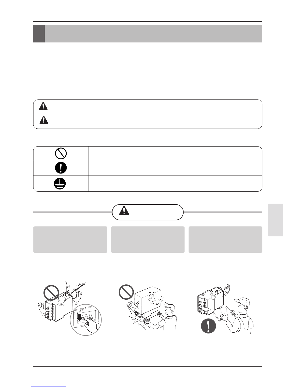
Safety Precautions
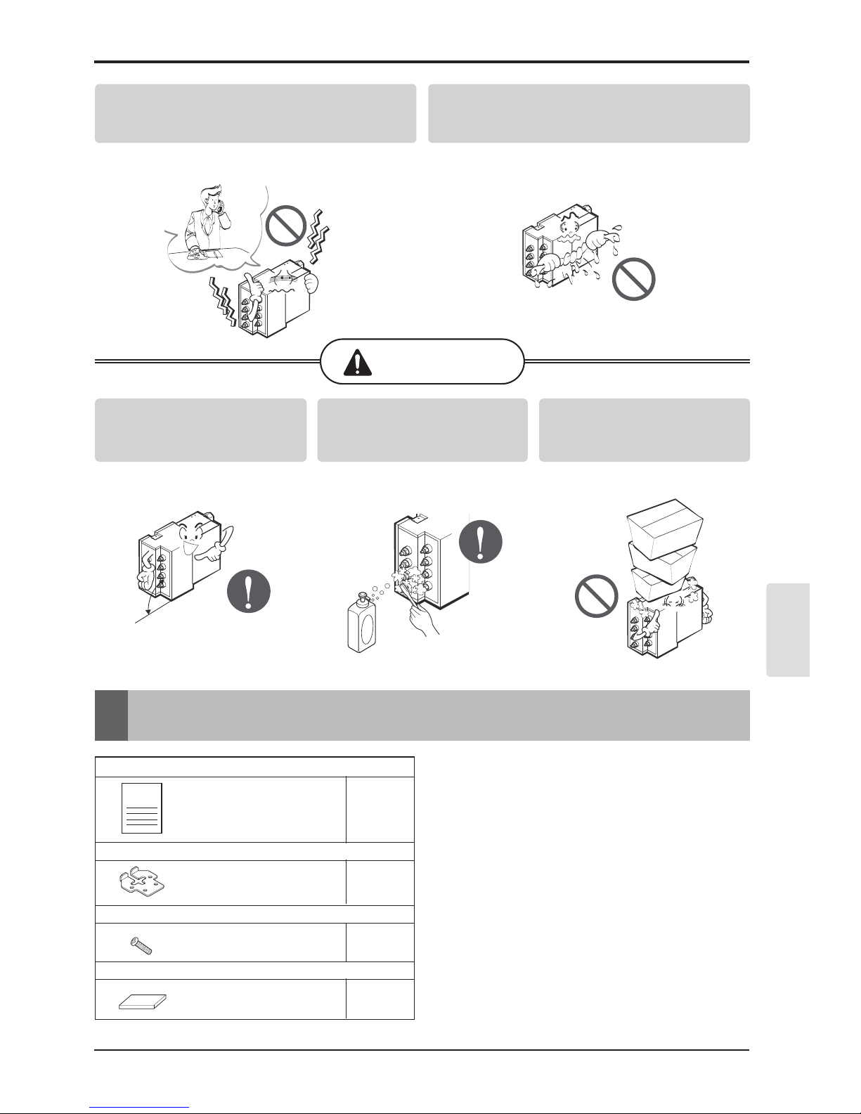
WARNING
For electrical work, contact the
dealer, seller, a qualified
electrician, or an Authorized
Service Center.
• Do not disassemble or repair the
product. There is risk of fire or
electric shock.
Be cautious when unpacking and
installing the product.
• Sharp edges could cause injury. Be
especially careful of the case edges
and the fins on the condenser and
evaporator.
Install the panel and the cover of
control box securely.
• There is risk of fire or electric shock.
Page 4
4 Branch Distributor
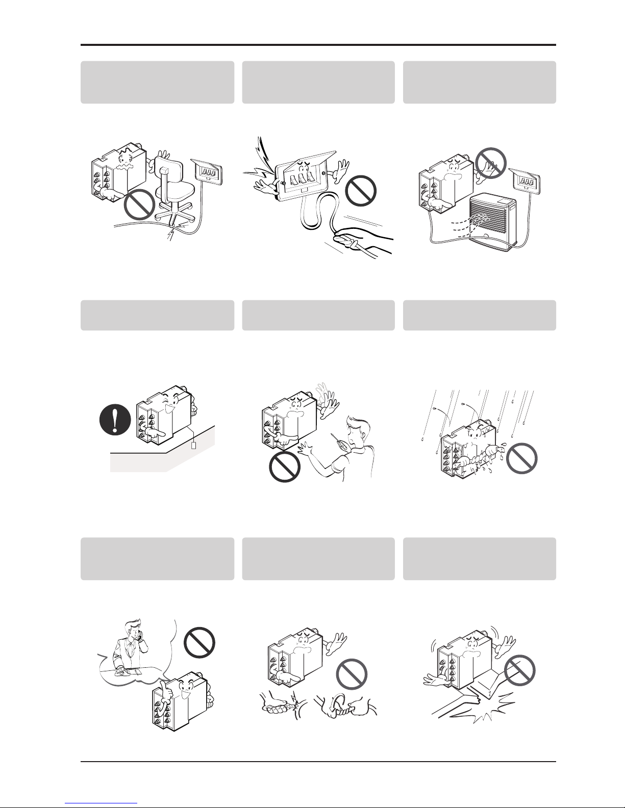
Safety Precautions
Do not place anything on the
power cable.
• There is risk of fire or electric shock.
Take care to ensure that power
cable could not be pulled out or
damaged during operation.
• There is risk of fire or electric shock.
Do not place a heater or other
appliances near the power cable.
• There is risk of fire and electric
shock.
Always ground the product.
There is risk of fire or electric shock
Do not install, remove, or re-install
the unit by yourself (customer).
• There is risk of fire, electric shock,
explosion, or injury.
Do not allow water to run into
electric parts.
• It may cause there is risk of fire,
failure of the product, or electric
shock.
For installation, always contact the
dealer or an Authorized Service
Center.
• There is risk of fire, electric shock,
explosion, or injury
Do not modify or extend the power
cable.
• There is risk of fire or electric shock.
Do not install the product on a
defective installation stand.
• It may cause injury, accident, or
damage to the product.
Page 5
Installation Manual 5
ENGLISH
CAUTION
Parts
1. INSTALLATION MANUAL
2. HANGER METAL
3. SCREWS
4. INSULATION PE
1 pc
4 pcs
8 pcs
2 pcs
Items to be prepared in the field
• Connecting wires
(AWG 18-4, AWG 16-4)
• Installation parts
(Hanging bolts: 4 x M10 or M8, Nuts: 12, flat
washers:8)
• Screws for wall-mounting : 6 x M5
• Insulation
• Brass cap
• Aluminum tape
If strange sound, or smell or smoke comes from
product.
• Turn the breaker off or disconnect the power supply
cable. There is risk of electric shock or fire
Do not let the air conditioner run for a long time when
the humidity is very high and a door or a window is
left open.
• Moisture may condense and wet or damage furniture.
Keep level even when installing
the product.
• To avoid vibration or water leakage.
Always check for gas (refrigerant)
leakage after installation or repair
of product.
• Low refrigerant levels may cause
failure of product.
Do not step on or put anyting on
the product. (outdoor units)
• There is risk of personal injury and
failure of product.
sj"
Safety Precautions
Page 6
6 Branch Distributor
Parts
PRECAUTIONS FOR SELECTING THE LOCATION
The BD unit is for indoor use. Install in a location such as above a ceiling or behind a wall in
accordance with the following conditions:
• That the unit is fully supported, and is in a location with little or no vibration.
• That the refrigerant pipes for the indoor and outdoor units can be repaired with ease, and that
the units are placed well within the distance from each other allowed by the pipe length.
• That there is nothing nearby that produces heat or steam(gas).
• When installing, that there is enough carity for servicing the unit.
• Do not install in location that is hot or humid for long periods of time.
• A well-ventilated area.
• Do not install near bedrooms. The sound of refrigerant flowing through the piping may
sometimes be audible. For restrictions on installation, refer to "INSTALLATION".
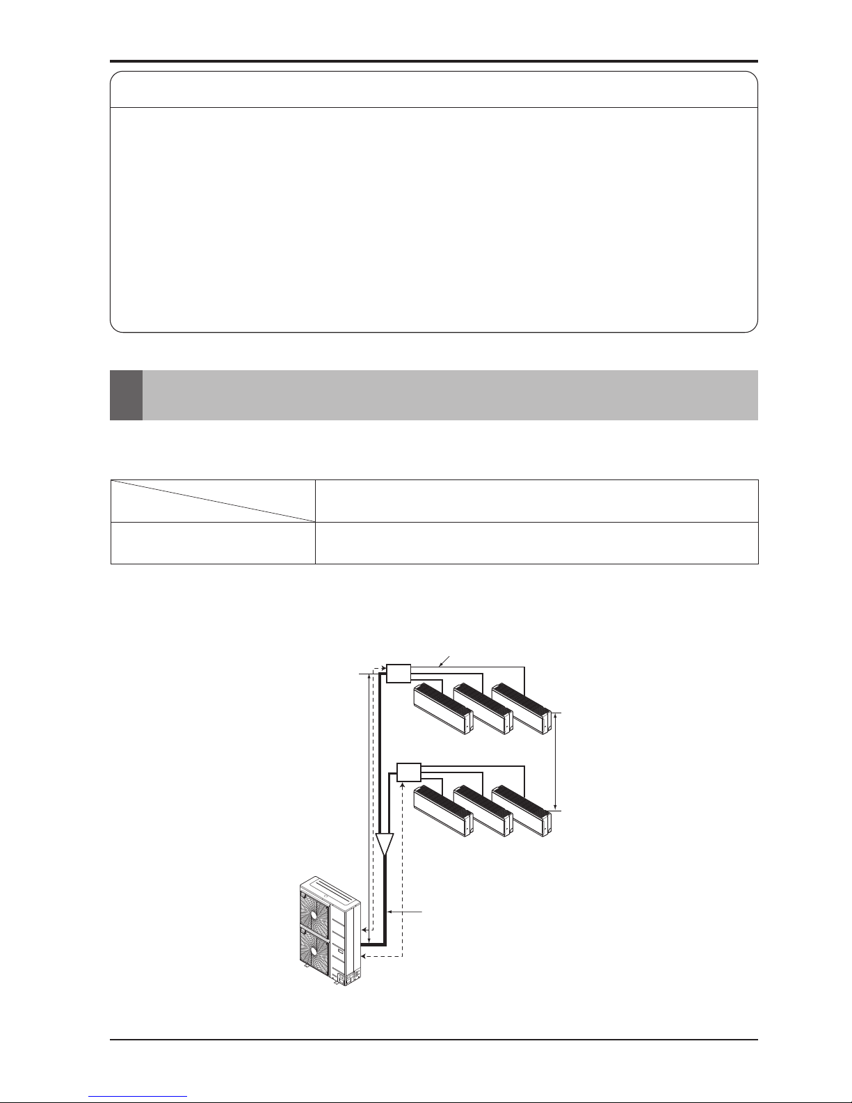
System Layout
For installation of the indoor units. Follow the instructions in the installation manual for each unit.
Do not connect more than 8 indoor units together choose the distributor unit type
(2rooms,3rooms or 4rooms) according to the installation pattern
Distributor Unit
h1
A
Branch Pipe
Main Pipe
Distributor
Distributor
B
h2
R410A
4 D4PBB
Rooms
Refrigerant
Page 7
Installation Manual 7
ENGLISH
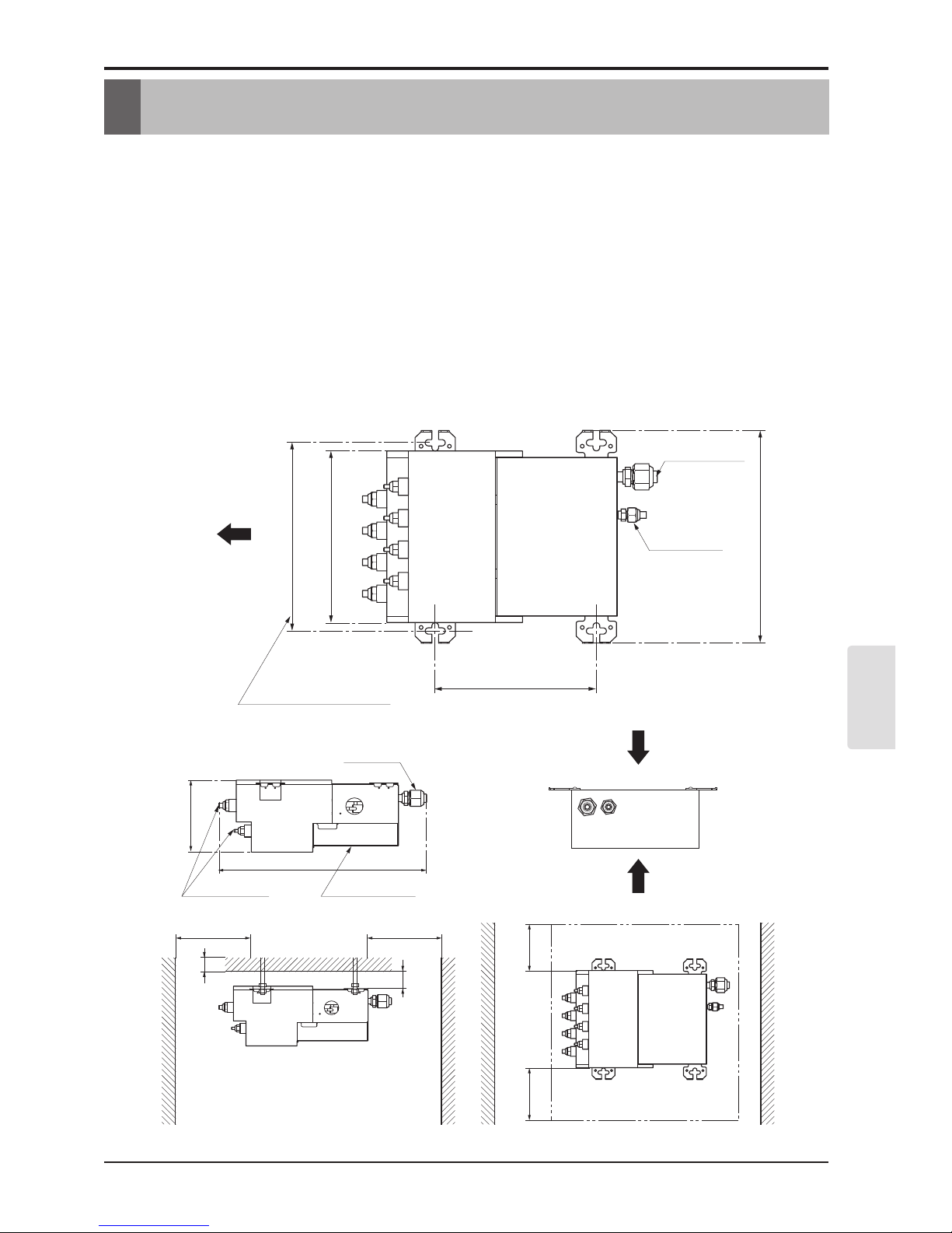
Installation
• This unit may be installed suspended from the ceiling or mounted on the wall.
• This unit may only be installed horizontally , as shown in the diagram below.(Side B is facing up)
However, it may be freely installed in any direction forward or back, and to the sides.
• Be sure to leave a 2ft square opening for service and inspection as shown in the diagram below,
for both ceiling - suspended installation and wall-mounted installation.
• This unit "does not require drain treatment" as it uses internal foam treatment as low-pressure
piping insulation.
• Service direction is the side B and C
• The piping for the indoor unit may be led around in direction A
• The inclination of side B must be within ±5 degrees forward or back or to the sides.
Min 15 3/4
Min 1 3/16
Min 3 15/16
Min 15 3/4
Branch Pipe
17
6 5/16
Cover Control
Main Pipe
(Servicing space)
B
C
Inspection opening
Min 11 13/16
Min 11 13/16
11 23/32
9 27/32
Ø3/4
Ø3/8
Suspension bolt pitch.
9 21/32
13 9/32
A
Unit : inch
Installation
Page 8
8 Branch Distributor
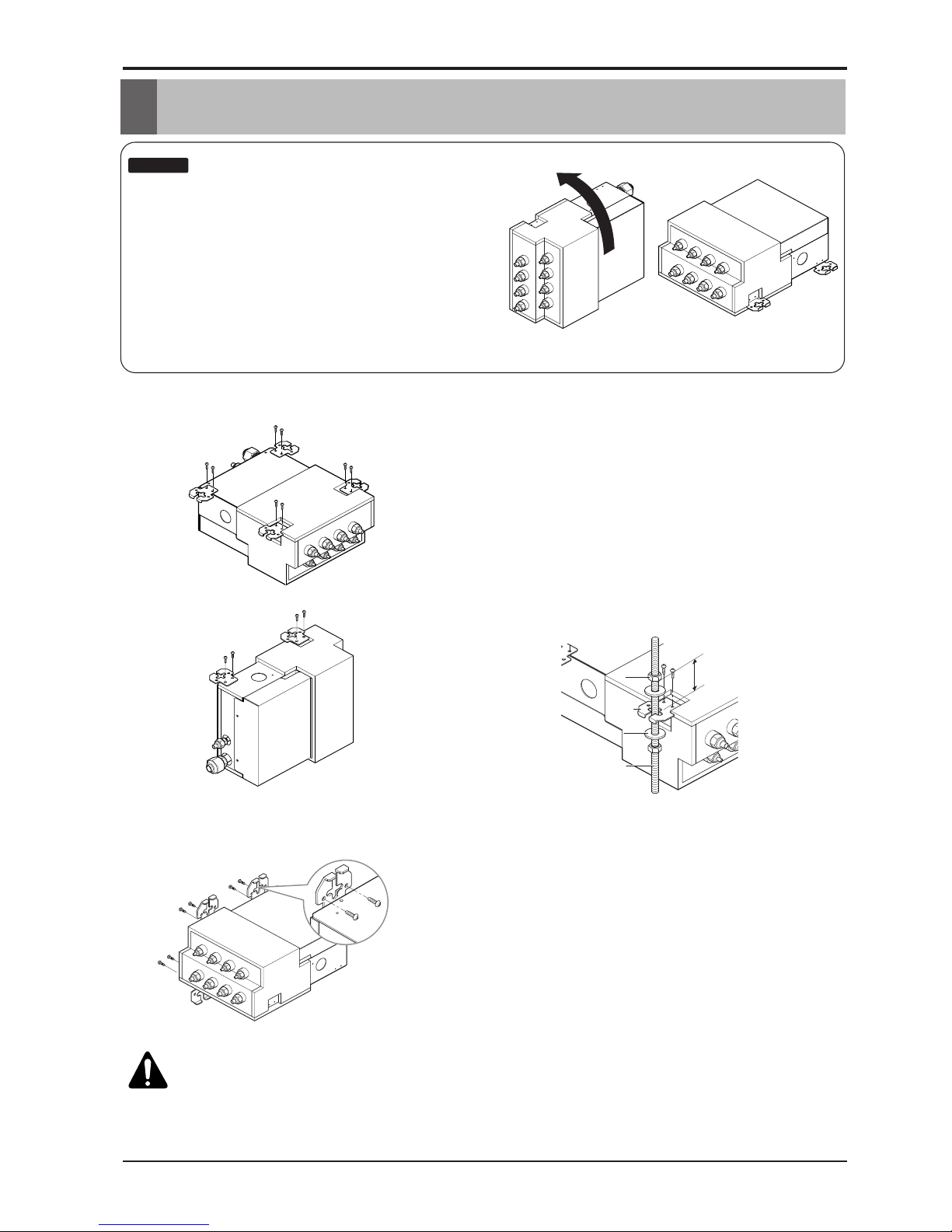
Installation of The Main Unit
Installation of The Main Unit
:
• This unit has two different installation types:
(1) Ceiling-suspended type and (2) wall-mounted type.
• Choose the proper installation pattern according to the
location of installation.
• The installation location for printed wiring board can be
changed.
Follow the procedure specified in the "CONNECTING
THE WIRING" section to change the location.
NOTICE
(1) Ceiling-suspended type
(2) Wall-mounted type
Screws(M5)
Screws(M5)
(locally procude)
(locally procude)
Screws(M5)
(locally procude)
BD unit
Six-sided Nut
Six-sided Nut
(M10 or M8)
(M10 or M8)
Six-sided Nut
(M10 or M8)
Hanger metal
Hanger metal
Hanger metal
Flat washer
Flat washer
Flat washer
Hanging bolt
Hanging bolt
Hanging bolt
(M10 or M8)
15.0(19/32)
Unit : mm(inch)
Procedure
(1) Fix the fumished hanger metal with two screws.(4 locations in
total).
(2) Using an insert-hole-in- anchor, hang the hanging bolt.
(3) Install a hexagon nut and a flat washer (locally-procured)to
the hanging bolt as shown in the figure in the left, and ift the
main unit to hang on the hanger metal.
(4) After checking with a level that the unit is level, tighten the
hexagon nut.
* The tilt of the unit should be within ±5° in front/back and
left/right.
Procedure
(1) Fix the fumished hanger metal with two screws.
(3 locations in total).
(2) After checking with a level that the unit is level, fix the
unit with the furnished wood screws.
* The tilt of the unit should be within ±5° in front/back and
left/right.
* Block up the parts of hanger holes (2 places) by using
insulation PE after installing the hanger.
CAUTIONS
• Once a screw-hole on the main unit has had a screw hammered in, make sure to either hammer it again
or cover it with alumium tape.(This is to prevent condensation)
• Be sure to install the unit with the ceiling-sie up.
• Do not install near bedrooms. the sound of refrigerant flowing through the piping may sometimes be
audible.
(1) Ceiling-suspended type (2) Wall-mounted type
Page 9
Installation Manual 9
ENGLISH
Connection of Piping
• When connecting indoor units, make sure to connect refrigerant pipes and connection wires to the appropriate
connection ports maked with matching alphabets. (A, B, C, D)
:
• Be sure to mark all the local refrigerant piping(liquid
pipes, gas pipes, etc.) for each indoor unit designating
clearly which room it belongs in.(A, B, C, D)
NOTICE
:
For flaring work the piping, follow the instructions in the installation manual to each unit.
NOTICE
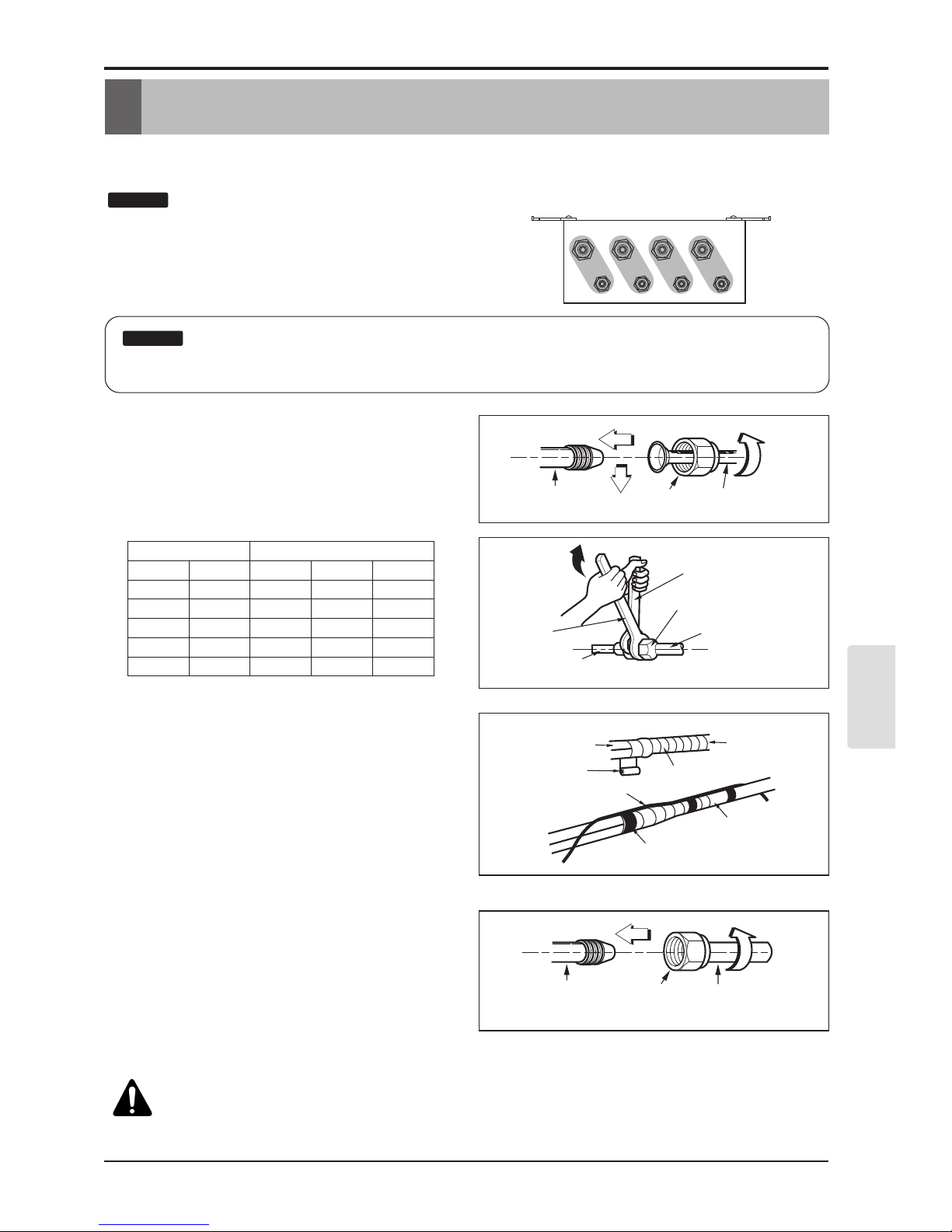
Connecting the pipings to the indoor
unit and drain hose to drain pipe
1. Align the center of the pipings and sufficiently
tighten the flare nut by hand.
2. Tighten the flare nut with a wrench.
Wrap the insulation material around
the connecting portion.
1. Overlap the connection pipe insulation
material and the indoor unit pipe insulation
material. Bind them together with vinyl tape
so that there is no gap.
2. Wrap the area which accommodates the rear
piping housing section with vinyl tape.
Close up a socket for unoccupied
room with a brass cap.
1. Align the center of the piping and sufficiently
tighten the brass cap by hand.
2. Tighten the brass cap with a wrench.
3. Wrap the joint part with insulation.
BD Unit Socket Flare nut Pipes
Wrench
BD Unit Socket
Open-end wrench (fixed)
Connection pipe
Flare nut
Vinyl tape(narrow)
BD Unit
Connecting cable
Vinyl tape (wide)
Wrap with vinyl tape
Indoor unit pipe
Pipe
BD Unit Socket Pipe sealed
or welded
Brass cap
DCBA
CAUTIONS
• Never use the plastic cap for sealing.
• Make sure to use brass cap with the end of
pipe sealed or welded tightly.
Connection of Piping
Outside diameter Torque
mm inch N. m kgf.m lbf.ft
Ø6.35 1/4 14~18 1.4~1.8 10~13
Ø9.52 3/8 34~42 3.5~4.3 25~31
Ø12.7 1/2 49~61 5.0~6.2 36~45
Ø15.88 5/8 69~82 7.0~8.4 51~60
Ø19.05 3/4 100~120 10.0~12.2 73~88
Page 10
10 Branch Distributor
Connection of Wiring
Connection of Wiring
• Connect refrigerant pipes and connection wires to the appropriate ports maked with matching
alphabets (A, B and C) on this unit.
• Follow the instructions on the wiring nameplate to connect the connection wires of indoor/outdoor
units to terminal board numbers.(1, 2 and 3) Always fix each ground wire separately with a ground
screw.(See the figure below.)
• After completing the wiring, fix the outer coating of wires securely with wire clamps. The wire
clamp on indoor unit side is furnished. Follow the procedure below to install.
• Refer to the circuit diagram on the control cover inside outdoor unit.
:
The terminal board numbers are arranged from top to bottom in order of 1, 2 and 3.
NOTICE
Page 11

Manuale d’installazione
Modèle : D4PBB
FRANÇAIS
Page 12

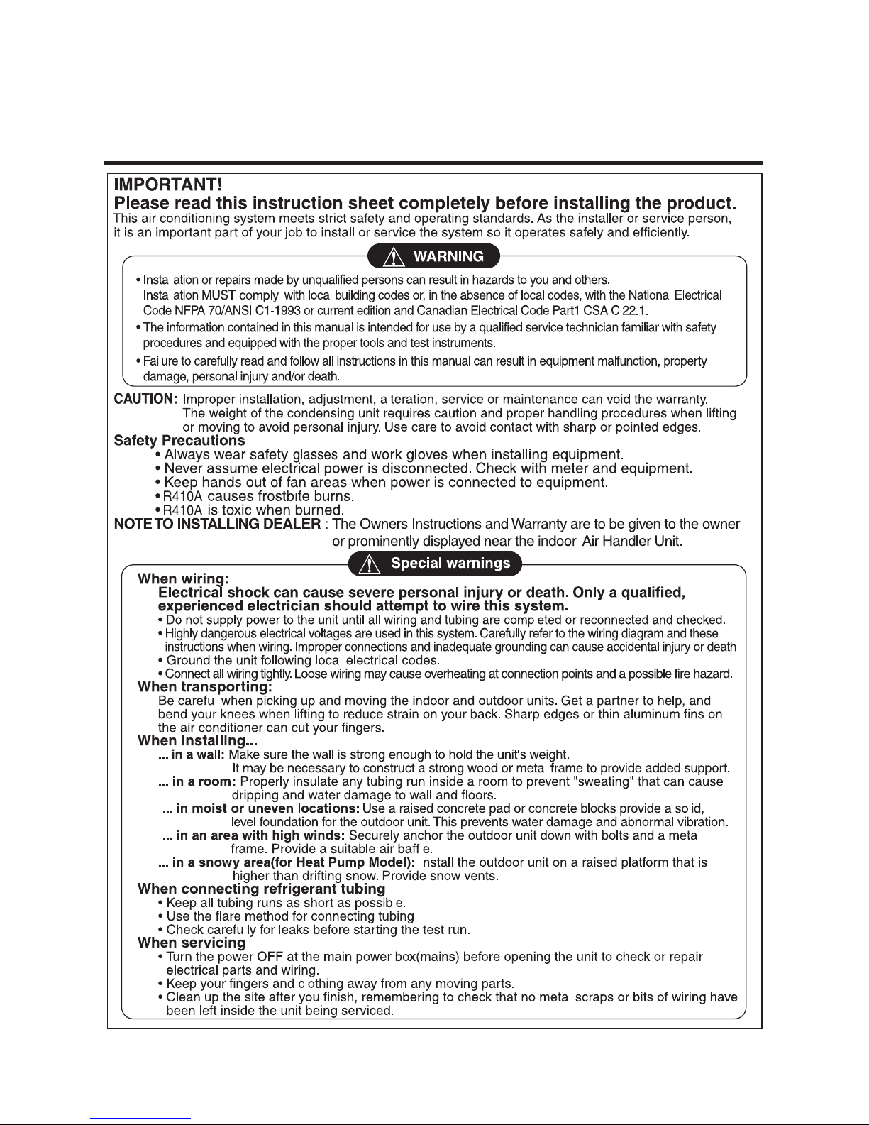
IMPORTANT!
Veuillez lire ces instructions au complet avant d’installer ce produit.
ATTENTION:
Mesures de sécurité
REMARQUE POUR L’INSTALLEUR :
Lors du câblage :
Lors du transport :
Lors de l’installation...
Lors de la connexion de la tuyauterie de réfrigération
Lors de la réparation
Ce système de climatisation réunit strictement les standards de sécurité et de fonctionnement. En tant qu’installeur ou technicien spécialisé, une partie
importante de votre travail consiste à installer et à réaliser le service technique de ce système d’une manière telle qu’il fonctionne de façon sûre et
efficiente.
Un défaut d’installation, du service technique ou dans l’entretien, et une réparation ou une modification
inappropriées peuvent annuler la garantie.
Le poids de l’unité de condensation exige des précautions et des procédures de manipulation appropriées au
moment de déposer ou déplacer l’unité afin d’éviter des blessures personnelles. Veillez à éviter également le
contact avec les bords pointus ou aiguisés.
Un choc électrique peut provoquer des blessures personnelles graves, voire la mort.
Seulement un électricien qualifié et expérimenté doit réaliser le câblage du système.
• Utilisez toujours des protections de sécurité pour les yeux et des gants de travail lors de l’installation de l’appareil.
• Assurez-vous toujours que l’alimentation soit coupée. Vérifiez-le à l’aide des dispositifs et des instruments appropriés.
• Gardez les mains loin du ventilateur lorsque l’appareil est branché.
• Le R410A provoque des gelures.
• Le R410A est toxique lorsqu’il est brûlé.
• Ne mettez pas l’unité sous tension jusqu’à ce que tout le câblage et le drainage soient complétés ou rebranchés et vérifiés.
• Des voltages électriques très dangereux sont utilisés dans ce système. Lisez avec soin le diagramme de câblage et ces instructions lors du
câblage. Des connexions inappropriées et une mise à la terre incorrecte peuvent provoquer des blessures, voire la mort.
• Mettez l’unité à la terre suivant les codes électriques locaux.
• Serrez bien les câbles. Un câble mal serré peut provoquer la surchauffe des points de connexion et constitue un risque d’incendie.
• Gardez tous les drainages les plus courts possible.
• Utilisez la méthode d’évasement pour raccorder les tuyaux.
• Vérifiez soigneusement s’il y a des pertes avant de commencer le drainage d’essai.
• Coupez l’alimentation principale (dans le tableau d’alimentation principale) avant d’ouvrir l’unité pour vérifier ou réparer les pièces et les
câbles électriques.
• Eloignez vos doigts et vos vêtements de toutes les pièces mobiles.
• Nettoyez le secteur après avoir fini. Assurez-vous qu’il n’y ait pas de tournure de fer ni de morceaux de câbles à l’intérieur de l’unité réparée.
Levez et transportez avec soin les unités intérieure et extérieure.
Cherchez de l’aide pour le faire et fléchissez vos genoux pour le déposer afin d’éviter l’effort de votre dos. Les bords aiguisés ou les rebords
tranchants d’aluminium du climatiseur peuvent vous couper les doigts.
...dans un mur : assurez-vous que le mur soit assez fort pour supporter le poids de l’unité.
Il peut être nécessaire de construire un cadre en bois ou en métal afin d’assurer un support supplémentaire.
...dans une pièce : Isolez de façon appropriée toute la tuyauterie de drainage dans la pièce pour éviter la « transpiration », qui peut
provoquer des égouttements et des problèmes d’humidité dans les murs et les planchers.
...dans des endroits humides ou non nivelés : Utilisez une base de béton ou des blocs de béton pour donner une base solide et nivelée à
l’unité extérieure.
Cela prévient les problèmes d’humidité et les vibrations anormales.
...dans un secteur avec des vents très forts : Ancrez l’unité extérieure solidement à l’aide de boulons et d’un cadre métallique. Assurez un
flux d’air approprié.
...dans un secteur ou il neige beaucoup (seulement pour le modèle Pompe à chaleur) : Installez l’unité extérieure sur une plateforme
élevée, qui se trouve au-dessus du niveau de la neige tombée. Installez des conduits d’échappement de neige.
Les Instructions pour le propriétaire et la Garantie sont remises au propriétaire ou affichées clairement près de l’unité intérieure de contrôle
d’air/chauffage.
Précautions spéciales
• Une installation ou une réparation réalisées par des personnes non qualifiées peut provoquer des accidents.
• L’installation DOIT être réalisée conformément aux codes de construction locaux ou, en absence de ces codes, conformément aux Code
électrique national NFPA 70/ANSI C1-1993 ou l’édition en vigueur, et conformément au Code électrique canadien Partie 1 CSA C.22.1.
• L’information contenue dans ce manuel a été conçue pour être utilisé par un technicien qualifié, informé des procédures de sécurité et équipé
avec les outils et les instruments d’essai appropriés.
• Si les instructions de ce manuel ne sont pas lues avec soin et respectées, cela peut provoquer un mauvais fonctionnement de l’appareil, un
dommage du bien, des blessures personnelles, voire la mort.
PRÉCAUTION
CORDON FLEX MULTIPLE DIVISÉ
ET CONSIGNES D’INSTALLATION
Page 13

Mesures de sécurité
Manuel D'installation 3
FRANÇAIS
Les instructions ci-après doivent être observées dans le but de prévenir tout risque de
dommages corporels ou matériels.
n L'utilisation non conforme, résultant de la négligence des instructions, est susceptible de
provoquer des dommages corporels ou matériels dont la gravité est signalée par les
indications suivantes :
n
Veillez à observer les précautions spécifiées dans ce manuel, puisqu’elles incluent d’items importants concernant la
sécurité.
n
L'utilisation non conforme, résultant de la négligence des instructions, est susceptible de provoquer des dommages
corporels ou matériels dont la gravité est signalée par les indications suivantes :
n Meanings of symbols used in this manual are as shown below.
AVERTISSEMENT
ATTENTION
Ce symbole indique un risque de blessure grave, voire mortelle.
Ce symbole indique un risque de blessure ou des dommages
matériels seulement.
Veillez à ne pas faire cela.
Veillez à suivre les instructions de ce manuel.
Mise à terre
Mesures de sécurité
AVERTISSEMENT
Pour toute réparation électrique,
contactez votre revendeur,
distributeur, un électricien qualifié
ou un centre de réparation agréé.
• N’essayez pas de démonter et de
réparer le produit. Ceci comporte un
risque de choc électrique ou
d’incendie.
Faites attention lors du déballage
et de l’installation du produit.
• Les arrêtes vives peuvent causer
des blessures corporelles. Soyez
particulièrement prudent avec les
arrêtes du caisson et les ailettes du
condensateur et de l’évaporateur.
Installez le panneau et le couvercle
du boîtier de contrôle avec
précaution.
• Ceci peut être la cause d’un choc
électrique ou d’un incendie.
Page 14

4 Unité Distributrice
Mesures de sécurité
Ne placez pas d’objets lourds sur
le câble électrique.
• Autrement, vous risquez de causer
un incendie ou un choc électrique.
Assurez-vous qu'on ne puisse pas
tirer des câbles ou les endommager
en cours de fonctionnement.
• Ceci risquerait de provoquer un
incendie ou un choc électrique
Ne placez pas le câble électrique
près d’un poêle, etc.
• Autrement, vous risquez de causer
un incendie ou un choc électrique.
Mettez toujours à terre le produit.
• Ne pas le faire peut causer un
incendie ou un choc électrique.
Ne démontez ni ne réparez vousmême l’appareil.
• Contactez votre distributeur et le
service après-vente.
Veillez à ne pas faire couler d'eau
sur les parties électrique
• Autrement, vous risquez de causer
un incendie, un choc électrique ou
le mauvais fonctionnement de
l’appareil.
Pour l'installation, contactez
toujours votre distributeur ou le
centre après-vente.
• Autrement, vous risquez de
provoquer un incendie, un choc
électrique, une explosion ou des
blessures.
N'utilisez pas un câble électrique
endommagé.
• Vous risquez de causer un incendie
ou un choc électrique.
N'installez pas le produit dans un
endroit inapproprié.
• Autrement, vous risquez de causer
des dommages ou un accident.
Page 15

Mesures de sécurité
Manuel D'installation 5
ATTENTION
Composants
Coupez le disjoncteur ou débranchez le câble
d’alimentation si vous constatez la présence de bruits
étranges, d’odeurs ou de fumée provenant de l’appareil.
• Autrement, vous risquez de causer un choc électrique ou
un incendie.
Ne faites pas marcher l’appareil pendant longtemps si
le taux d’humidité est élevé, et laissez une porte ou
une fenêtre ouverte.
• Autrement, l'eau peut couler, en mouillant et en abîmant
vos meubles, etc
Maintenez le niveau, même lors de
l’installation du produit.
• Autrement, vous risquez de
provoquer des vibrations ou une
fuite d'eau.
Après installation ou réparation du
produit, veillez toujours à vérifier
qu’il n’y ait pas de fuite de gaz.
• Autrement, vous risquez de causer
le mauvais fonctionnement de
l'appareil.
Ne montez sur l’appareil ni n’y
placez aucun objet.
•
Autrement, vous risquez de vous
blesser ou de causer le mauvais
fonctionnement de l’appareil.product.
qh"
Pièces à préparer sur le sol
• Câble de connexion
(AWG 18-4, AWG 16-4)
• Composants d’installation
(Boulon de suspension : 4xM10 ou M8, 12
écrous, 8 rondelles plates)
• Vis pour montage mural : 6 x M5
• Isolant
• Embout en laiton
• Ruban d’aluminium
FRANÇAIS
1. Manuel d’installation
2. Dispositif de suspension en métal
3. Vis
4. Isolant
1
pièce
4 pièces
8 pièces
2 pièces
Page 16

6 Unité Distributrice
Composants
PRÉCAUTIONS CONCERNANT LE CHOIX DE L’EMPLACEMENT
Celle-ci est une unité d’intérieur. Installez-la suspendue au plafond ou montée au mur, selon les conditions suivantes :
• Que l'unité soit bien fixée, et qu’elle se trouve dans un endroit avec peu ou pas de vibration.
• Que les tuyaux de réfrigération des unités intérieure et extérieure puissent être réparés facilement, et que les
unités soient bien placées, en respectant la distance entre l’une et l’autre, suivant la longueur du tuyau.
• Qu’il n’y ait aucune source de chaleur ou de vapeur (gaz) à proximité.
• Lors de l’installation, qu’il y ait assez de lumière pour entretenir l'unité.
• N'installez pas l’unité dans des endroits où il fait chaud ou humide pendant de longues périodes.
• Choisissez un endroit bien aéré.
• N'installez pas l’unité près des chambres à coucher. Le bruit du réfrigérant coulant à l’intérieur de la tuyauterie
peut parfois être audible. Pour des restrictions concernant l'installation, reportez-vous au chapitre «
INSTALLATION ».
Schéma du Système
Pour l'installation des unités intérieures. Suivez les instructions du manuel d'installation pour chaque unité.
Ne raccordez pas ensemble plus de 8 unités intérieures. Choisissez le type d'unité distributrice (2
pièces, 3 pièces ou 4 pièces) selon le modèle d'installation.
h1
A
Tuyau de raccordement
Tuyau principal
Distributeur
Distributeur
B
h2
Unité Distributrice
R410A
4 D4PBB
Pièces
Refrigerant
Page 17

Installation
Manuel D'installation 7
Installation
• Cette unité peut être installée soit suspendue au plafond soit en applique murale.
• Cette unité peut être installée uniquement en position horizontale, tel qu’il est montré sur le
diagramme ci-dessous (le côté B est orienté vers le haut). Toutefois, elle peut être librement
installée dans n’importe quelle direction en avant ou en arrière, et sur les côtés.
• Assurez-vous de laisser une ouverture carrée de 2ft pour le service et l'inspection tel qu’il est
montré sur le diagramme ci-dessous, aussi bien dans le cas d’une installation de type suspendue
au plafond que dans celui d’une installation en applique murale.
• Cette unité "n’a pas besoin d’un traitement de drainage" car elle utilise un traitement de mousse
interne qui sert à isoler la tuyauterie à basse pression.
• Les côtés B et C constituent la direction de service.
• La tuyauterie pour l'unité intérieure peut être dirigée dans la direction A.
• L’inclinaison du côté B doit être de ±5 degrés en avant ou en arrière ou sur les côtés.
Min 15 3/4
Min 1 3/16
Min 3 15/16
Min 15 3/4
(Espace pour le service)
Ouverture pour l’inspection
Min 11 13/16
Min 11 13/16
11 23/32
9 27/32
Ø3/4
Ø3/8
Distance entre Boulons de suspension
9 21/32
13 9/32
A
Unité: pouces
B
C
Tuyau de Raccordement
17
6 5/16
Couvercle du Panneau de Commande
Tuyau Principal
FRANÇAIS
Page 18

8 Unité Distributrice
Installation de l'Unité Principale
Installation de l'Unité Principale
:
• Cette unité a deux types d'installation différents:
(1) Type suspendu au plafond et (2) type en applique
murale.
• Choisissez le modèle d'installation approprié selon
l’endroit d'installation.
• L'endroit d'installation du panneau à circuit imprimé
peut être changé.
En cas de changement de l'emplacement, suivez la
procédure spécifiée dans la section "RACCORDEMENT
DU CÂBLAGE".
REMARQUE
(1) Type suspendu au plafond
(2) Type montage mural
Vis (M5)
(localement procude)
Vis (M5)
(localement procude)
15.0(19/32)
Flat washer
Flat washer
Hanger metal
Hanger metal
Unité BP
Hanging bolt
Hanging bolt
Six-sided Nut
Six-sided Nut
(M10 or M8)
(M10 or M8)
Boulon de suspension
(M10 or M8)
Support métallique
Rondelle plate
Écrou hexagonal
(M10 ou M8)
Unité: mm (pouces)
Procédure
(1) Fixez les supports métalliques fournis à l’aide de deux vis (4
positions au total).
(2) Fixez les boulons de suspension à l’aide d’une riveteuse.
(3) Installez un écrou à six pans et une rondelle plate (procurez-
vous-les sur place) pour le boulon de suspension, tel qu’il est
montré sur la figure à gauche, et placez l'unité principale en
l’accrochant aux supports métalliques.
(4) Après avoir vérifié, à l’aide d’un niveau, que l'unité est
horizontale, serrez l'écrou à six pans.
* L'inclinaison de l'unité devrait être de ±5° en avant ou en
arrière et à gauche ou à droite.
Procédure
(1) Fixez le dispositif de suspension en métal fourni avec
deux vis. (3 endroits au total)
(2) Après vérification avec un niveau que l’appareil est bien
droit, fixez l’appareil avec les vis à bois fournis.
* l’appareil doit être incliné à environ 5° de l’avant vers
l’arrière et de la gauche vers la droite.
* Après son installation, bouchez les trous du dispositif de
suspension (2 emplacements) à l’aide d’un joint isolant.
AVERTISSEMENTS
• Si une vis a déjà été insérée dans un trou à vis de la partie principale, assurez-vous de bien réinsérer
une autre vis, ou bien de couvrir le trou avec une bande aluminium. (Afin d’éviter toute condensation).
• Assurez-vous d’installer l’appareil dans le bon sens (le haut vers le plafond)
• Ne pas installer l’appareil près des chambres à coucher. Vous pouvez parfois écouter le bruit du réfrigérant
circuler dans la tuyauterie.
(1) Type suspendu au plafond (2) Type en applique murale
Page 19

Raccordement de la tuyauterie
Manuel D'installation 9
Raccordement de la tuyauterie
• Lors du raccordement des unités intérieures, veillez à raccorder les tuyaux de réfrigération et les câbles de
connexion aux ports de connexion appropriés, identifiés par des lettres (A, B, C, D).
:
• Assurez-vous d’identifier toute la tuyauterie de
réfrigération locale (les tuyaux à liquide, les tuyaux à gaz,
etc.) en indiquant clairement, pour chaque unité
intérieure, à quelle pièce elle correspond. (A, B, C, D)
REMARQUE
:
Pour ce qui est du travail d’évasement de la tuyauterie, suivez les instructions du manuel
d'installation pour chaque unité
REMARQUE
Raccordement de la tuyauterie à
l’unité intérieure et des raccords de
drainage aux tuyaux de drainage.
1. Alignez le centre des tuyaux et serrez bien à
la main l'écrou évasé.
2. Serrez l'écrou évasé à l’aide d’une clé.
Enveloppez avec du matériau isolant
la partie à raccorder.
1. Recouvrez le matériau isolant du tuyau de
connexion et le matériau isolant du tuyau de
l’unité intérieure. Attachez-les entre eux avec
du ruban adhésif, de sorte qu'il ne reste
aucune ouverture.
2. nveloppez avec du ruban adhésif le secteur
qui loge la section arrière de la tuyauterie de
la maison.
Fermez l'emboîture pour une pièce
sans occupants à l'aide d'un
bouchon en laiton.
1. Alignez le centre du tuyau et serrez à la main
suffisamment le bouchon en laiton.
2. Serrez le bouchon en laiton à l'aide d'une clé.
3. Enveloppez le joint avec du matériel isolant.
Emboîture de l'unité distributrice
Écrou évasé
Tuyau
Clé
Emboîture de l'unité distributrice
Clé à fourche (fixe)
Tuyau de connexion
Écrou évasé
Emboîture de
l'unité distributric
Tuyau scellé
ou soudé
Bouchon
n laiton
Ruban adhésif (étroit)
Unité distributrice
Câble de raccordement
Ruban adhésif
(large)
Enveloppez avec du ruban adhésif
Tuyau de
l'unité intérieure
Tuyau
DCBA
PRÉCAUTIONS
• N'utilisez jamais un bouchon en plastique pour sceller l'emboîture.
• Veillez à utiliser le bouchon en laiton avec l'extrémité d'un tuyau fermement scellé ou soudé.
FRANÇAIS
Diamètre extérieur Couple
mm pouce N. m kgf.m lbf.ft
Ø6.35 1/4 14~18 1.4~1.8 10~13
Ø9.52 3/8 34~42 3.5~4.3 25~31
Ø12.7 1/2 49~61 5.0~6.2 36~45
Ø15.88 5/8 69~82 7.0~8.4 51~60
Ø19.05 3/4 100~120 10.0~12.2 73~88
Page 20

10 Unité Distributrice
Raccordement du Câblage
Raccordement du Câblage
• Raccordez les tuyaux de réfrigération et les câbles de connexion aux ports appropriés, identifiés
par des lettres (A, B, et C) sur cette unité.
• Suivez les instructions qui se trouvent sur la plaque signalétique du câblage lors du raccordement
des câbles de connexion des unités intérieure et extérieure aux numéros de la plaque à bornes
(1, 2 et 3). Fixez toujours chaque câble à terre séparément à l’aide d’une vis de mise à la terre
(Voir figure ci-dessous.).
• Une fois le câblage terminé, fixez fortement le revêtement extérieur des câbles avec des serrecâbles. Les serre-câbles de l’unité intérieure sont fournis. Suivez la procédure ci-dessous pour
l’installation.
:
Les numéros de la plaque à bornes sont établis de haut en bas suivant l’ordre de 1, 2, et 3.
REMARQUE
Page 21

Manual de Instalzción
SPLIT SYSTEM DUCTLESS
Modelo : D4PBB
ESPAÑOL
Page 22

¡IMPORTANTE!
Lea completamente este manual de instrucciones antes de instalar el producto.
PRECAUCIÓN:
Precauciones de seguridad
NOTA PARA EL INSTALADOR:
Al realizar la conexión:
Al realizar el transporte:
Al realizar la instalación...
Al conectar las tuberías de refrigerante
Al realizar el mantenimiento
Este sistema acondicionador de aire cumple estrictamente las normas de funcionamiento y seguridad. Como instalador o persona de mantenimiento,
una parte importante de su trabajo es instalar o realizar el mantenimiento del sistema de modo que funcione de modo eficiente y seguro.
La instalación, ajuste, modificación, reparación o mantenimiento inadecuados pueden anular la garantía.
Dado el peso de la unidad condensadora se requiere precaución y la utilización de procedimientos de
manejo adecuados al levantarla o desplazarla para evitar lesiones personales. Evite el contacto con los
bordes afilados o puntiagudos.
Una descarga eléctrica puede producir graves lesiones personales o muerte. Sólo debe
realizar la conexión de este sistema un electricista cualificado y experimentado.
• Utilice siempre material de protección para los ojos y guantes de trabajo para instalar el equipo.
• Nunca dé por hecho que el suministro eléctrico está desconectado. Compruébelo con el medidor y el equipamiento.
• Mantenga las manos alejadas de las zonas de ventiladores cuando la alimentación esté conectada al equipo.
• R410A produce quemaduras por congelación.
• R410A es tóxico cuando se quema.
• No suministre energía a la unidad hasta que se hayan completado o reconectado y comprobado todas las conexiones y tuberías.
• Este sistema utiliza voltajes eléctricos altamente peligrosos. Consulte atentamente el esquema de cableado y estas instrucciones cuando
realice las conexiones. Una conexión incorrecta y una puesta a tierra inadecuada pueden ocasionar lesiones por accidente o muerte.
• Ponga a tierra la unidad siguiendo los códigos eléctricos locales.
• Apriete fuertemente todas las conexiones. Los cables flojos pueden causar un sobrecalentamiento en los puntos de conexión y un posible
peligro de incendio.
• Mantenga la longitud de todas las tuberías lo más corta posible.
• Utilice el método de abocinado para conectar las tuberías.
• Compruebe con cuidado las fugas antes de realizar la prueba de funcionamiento.
• Desconecte la alimentación en el cuadro principal (red) antes de abrir la unidad para comprobar o reparar piezas eléctricas y el cableado.
• Mantenga alejados los dedos y la ropa de las piezas móviles.
• Limpie la zona antes de finalizar el mantenimiento, recordando comprobar que no quedan en el interior de la unidad residuos metálicos o
trozos de cableado.
Tenga cuidado al recoger y desplazar las unidades interior y exterior. Es necesario la ayuda de otra persona y doblar las rodillas al levantar la
unidad para reducir la tensión en su espalda. Los bordes afilados o las aletas de aluminio delgado del acondicionador de aire pueden producir
cortes en los dedos.
... en una pared: Asegúrese de que la pared es lo suficientemente resistente como para soportar el peso de la unidad.
Puede que sea necesario construir un bastidor de metal o madera resistente para proporcionar más apoyo.
... en una habitación: Aísle adecuadamente cualquier tubería situada en el interior de una habitación para evitar la “condensación” que
puede producir goteo y daños en pared y suelo.
... en emplazamientos húmedos o no uniformes: Utilice una base de hormigón elevada o bloques de hormigón para proporcionar una base
sólida y nivelada para la unidad exterior. Esto evita los daños por agua y las vibraciones anormales.
... en áreas con fuertes vientos: Ancle firmemente la unidad exterior con pernos y un bastidor metálico. Instale un deflector de aire
adecuado.
... en áreas con nieve (para el modelo de bomba de calor): Instale la unidad la unidad exterior sobre una plataforma elevada a un nivel
más alto que el de la nieve. Instale rejillas para la nieve.
El manual de instrucciones y la garantía deben entregarse al propietario o quedar expuestos a la vista cerca de la unidad interior de
ventilación/calefacción.
Advertencias especiales
• La instalación o reparaciones realizadas por personas no cualificadas pueden poner en riesgo a las personas.
La instalación DEBE cumplir los códigos locales de construcción o, en ausencia de códigos locales, el Código Eléctrico Nacional NFPA
70/ANSI C1-1993 o la edición actual y el Código Eléctrico de Canadá Parte 1 CSA C.22.1.
• La información contenida en el manual está pensada para ser utilizada por un técnico cualificado familiarizado con los procedimientos de
seguridad y equipado con las herramientas e instrumentos de comprobación adecuados.
• Si no lee atentamente ni sigue las instrucciones de este manual puede producirse un mal funcionamiento en el equipo, daños materiales,
lesiones personales y/o muerte.
ADVERTENCIA
INSTRUCCIONES DE INSTALACIÓN DE
FLEX CON MÚLTIPLES DIVISIONES
Page 23

Precauciones de seguridad
Manual de Instrucciones 3
ESPAÑOL
Para evitar lesiones al usuario o a otras personas y daños a la propiedad, siga estas
instrucciones.
n Una operaci’on incorrecta por ignorar las instrucciones provocará lesiones o daños. La
seriedad se clasifica por las siguientes indicaciones.
n
Observe las precauciones especificadas en este manual, ya que incluyen indicaciones importantes relacionadas con la seguridad.
n
El uso incorrecto ocasionado al ignorar las instrucciones puede causar lesiones o daños. La gravedad se
clasifica mediante las siguientes indicaciones.
n Meanings of symbols used in this manual are as shown below.
ADVERTENCIA
PRECAUCIÓN
Este símbolo indica la posibilidad de muerte o de seria lesión.
Este símbolo indica sólo la posibilidad de lesión o daño a la propiedad.
Prohibido.
Recuerde seguir las instrucciones.
Asegúrese de establecer una conexión a tierra.
Precauciones de seguridad
ADVERTENCIA
Para trabajos eléctricos, entre en
contacto con el distribuidor, el
vendedor, un electricista cualificado,
o un centro de servicio autorizado.
• No desmonte o repare el producto
usted mismo.
Tenga cuidado al desembalar e
instalar el aparato. Tenga cuidado
al desempaquetar e instalar el
producto.
•
Los bordes afilados podrían causar
lesiones. Tenga especial cuidado con
las rebabas de la carcasa y las rebabas
en el condensador y el evaporador.
Instale firmemente el panel y la
cubierta de la caja de control.
• Existe riesgo de fuego o descarga
eléctrica.
Page 24

4 Distribuidor de la Sucursal
Precauciones de seguridad
No coloque objetos pesados sobre
el cable de alimentación
• De lo contrario, pueden ocurrir
descargas eléctricas o incendios
Asegúrese de que el cable de
alimentación no pueda estirarse o
dañarse durante el funcionamiento.
• Existe riesgo de incendio o
descarga eléctrica.
No ponga el calentador, etc., cerca
del cable de alimentación.
• De lo contrario, pueden ocurrir
incendios y descargas eléctricas.
Instale siempre una toma a tierra
para el aparato.
Provocará incendios o descargas
eléctricas
No desmonte ni repare el
producto.
• Contacte con su vendedor y centro
de servicio
No permita que entre agua en las
piezas elèctricas.
• De lo contrario, puede provocar
incendios o fallos en el producto,
así como descargas eléctricas.
Para la instalación, póngase en
contacto siempre con su vendedor
o centro de servicio.
• De lo contrario, pueden ocurrir
incendios, descargas eléctricas,
explosiones o lesiones.
No utilice cables de alimentación
dañado
• Provocará incendios o descargas
eléctricas
No instale el producto en una
superficie de instalación insegura.
• De lo contrario, pueden ocurrir
lesiones o accidentes.
Page 25

Precauciones de seguridad
Manual de Instrucciones 5
PRECAUCIÓN
Piezas
Elementos a preparar in situ
• Cables de conexión
(AWG 18-4, AWG 16-4)
• Piezas de instalación
(Pernos de suspensión: 4 x M10 ó M8,
arandelas: 12, arandelas planas: 8)
Tornillos para el montaje en pared: 6x M5
• Aislamiento
• Tapa de bronce
• Cinta de aluminio.
Si oye algún ruido extraño, o ve salir humo del
producto, apague el disyuntor o descoencte el cable
de alimentación.
• De lo contrario, puede ocurrir una descarga eléctrica o
incendio
No opere el producto durante largo tiempo en lugares
de alta humedad ni deje ninguna puerta ni ventana
abierta.
• De lo contrario podrái entrar agua y dañar o mojar los
muebles, etc.
Mantenga nivelado el producto
incluso al instalarlo.
• De lo contrario se podría causar
vibraciones o escapes de agua
Inspeccione siempre las fugas de
gas después de la instalación y
reparación del aparato.
• De lo contrario, puede provocar
fallos en el producto.
No desmonte ni coloque nada
sobre el producto.
•De lo contrario, puede provocar
incendios o fallos en el producto.
90˚
ESPAÑOL
1. MANUAL DE INSTALACIÓN
2. BISAGRA DE SUSPENSIÓN, METAL
3. TORNILLOS
4. AISLAMIENTO
1 pieza
4 pieza
8 pieza
2 pieza
Page 26

6 Distribuidor de la Sucursal
Piezas
PRECAUCIONES PARA SELECCIONAR LA UBICACIÓN
La unidad BD es para uso en interior únicamente. Instale en un lugar tal como un techo o detrás de una
pared de acuerdo con las siguientes instrucciones:
• La unidad tiene que quedar totalmente soportada y estar un lugar con poca o ninguna vibración.
• Las tuberías del refrigerante de las unidades interiores y exteriores pueden repararse con facilidad, y las
unidades están bien colocadas a la distancia permitida una de otra por el largo de la tubería.
• No debe haber nada cerca que roduzca calor o vapor (gas).
• Al instalar, debe haber suficiente cavidad para poder llevar a cabo tareas de servicio en la unidad.
• No instalar en un lugar que esté caliente o húmedo durante largos períodos de tiempo.
* Un área bien ventilada.
* No instale la unidad cerca de dormitorios. El sonido del refrigerante fluyendo por las tuberías puede
oírse en ocasiones. Para restricciones en la instalación, consulte “INSTALACIÓN”.
Disposición del sistema
Para la instalación de las unidades de interior, siga las instrucciones del manual de instalación de cada unidad.
No conecte más de 8 unidades de interior juntas. Elija el tipo de unidad de distribuidor (2 salas, 3
salas o 4 salas) de acuerdo con el modelo de instalación
h1
A
Conductos secundarios
Conducto principal
Distribuidor
Distribuidor
B
h2
Unidad del distribuidor
R410A
4 D4PBB
Salas
Refrigerant
Page 27

Instalación
Manual de Instrucciones 7
Instalación
• Esta unidad puede instalarse suspendida desde el techo o montada en la pared.
• Esta unidad únicamente puede instalarse horizontalmente, como se muestra en el diagrama de
abajo. (Cara B mirando hacia arriba).
Sin emabrgo, puede instalarse libremente en cualquier dirección hacia delante o hacia atrás, y a
los lados.
• Asegúrese de dejar una abertura de 2ft cuadrados para servicio e inspección como se muestra
en el diagrama de abajo, tanto para instalaciones suspendidas en el techo como para
instalaciones montadas en la pared.
• La unidad “no requiere tratamiento para drenajes”, ya que usa tratamiento interno de espuma
como aislamiento a baja presión de las tuberías.
• Dirección de servicio para los lados B y C.
• Las tuberías de la unidad de interior pueden encaminarse por la dirección A
• La inclinación del lado B debe estar dentro de los ±5 hacia delante o atrás o laterales.
Min 15 3/4
Min 1 3/16
Min 3 15/16
Min 15 3/4
(Espacio de servicio)
Abertura de inspección
Min 11 13/16
Min 11 13/16
11 23/32
9 27/32
Ø3/4
Ø3/8
Paso del perno de suspensión.
9 21/32
13 9/32
A
Unidad: pulgadas
B
C
Ramal de tubería
17
6 5/16
Control de la cubierta
Tubería principal
ESPAÑOL
Page 28

8 Distribuidor de la Sucursal
Instalación de la unidad principal
Instalación de la unidad principal
:
• Esta unidad tiene dos tipos diferentes de instalación:
(1) Suspendido en el techo y (2) montaje en pared.
• Elija el modelo de instalación adecuado de acuerdo
con la ubicación de la instalación.
• La ubicación de la instalación de la placa de cableado
impreso puede cambiarse.
Siga el procedimiento especificado en la sección
“CONEXIÓN DEL CABLEADO” para cambiar el lugar.
AVISO
(1) Tipo suspendido en el techo
(2) Tipo montado en pared
Tornillos (M5)
(no incluidos)
Tornillos (M5)
(no incluidos)
15.0(19/32)
Unidad: mm (pulgadas)
Arandela plana
Arandela plana
Unidad BD
Hanging bolt
Hanging bolt
Tuerca hexagonal
(M10 o M8)
Tuerca hexagonal
(M10 o M8)
Colgador metálico
Colgador metálico
Tornillo colgador
(M10 o M8)
Tornillo colgador
(M10 o M8)
Procedimiento
(1) Fije el colgador metálico que se suministra con los dos
tornillos. (4 lugares en total).
(2) Usando un anclaje tipo “insertar en agujero”, cuelgue el
tornillo colgador.
(3) Instale una tuerca hexagonal y una arandela plana
(adquisición local) a la tuerca colgadora como se muestra en
la figura de la izquierda y levante la unidad principal para
colgarla en el colgador metálico.
(4) Después de chequear con un nivel que la unidad está
nivelada, apriete la tuerca hexagonal.
• La inclinación de la unidad debería estar en ±5° en la parte
delantera/posterior e izquierda/derecha.
Procedimiento
(1) Fije la bisagra de suspensión de metal suministrada con
dos tornillos. (3 ubicaciones en total).
(2) Fije la unidad con los tornillos de madera suministrados
tras comprobar con un nivel que la unidad está nivelada.
• La inclinación de la unidad deberá estar entre ±5° en la
parte frontal/posterior e izquierda/derecha.
*
Bloquee las partes de los agujeros de la suspensión (2 lugares)
empleando aislante PE una vez instalada la suspensión.
PRECAUCIONES
• Una vez golpeado un tornillo en el agujero para tornillos de la unidad principal, asegúrese de volver a
golpearlo o cubrirlo con cinta de aluminio. (Para evitar la condensación)
• Asegúrese de instalar la unidad con el lado del techo hacia arriba.
•
No instale la unidad cerca de un dormitorio, ya que el ruido del flujo de refrigerante a través de las cañerías
podría resultar audible.
(1) Tipo suspendido en el techo (2) Tipo de montaje en pared
Page 29

Conexión de las tuberías
Manual de Instrucciones 9
Conexión de las tuberías a la unidad
de interior y la manguera de drenaje a
la tubería de drenaje.
1. Alinee el centro de las tuberías y apriete
suficientemente la tuerca de soldaje a mano.
2. Apriete la tuerca de soldaje con una llave
inglesa.
Envuelva con material de
aislamiento el tramo de conexión.
1. Solape el material de aislamiento de la
tubería de conexión y el material de
aislamiento de la tubería de la unidad interior.
Encinte el conjunto con cinta de vinilo de
modo que no queden huecos.
2. Encinte el área que alberga la sección
posterior del alojamiento de las tuberías con
cinta de vinilo.
Cerrar completamente con una tapa
de latón un tubo de enchufe para
una sala cerrada
1. Alinee el centro de la tubería y apriete
suficientemente la tapa de latón a mano.
2. Apriete la tapa de latón con una llave inglesa.
3. Aísle la junta.
Conexión de las tuberías
• l Al conectar las unidades internas, asegúrese de conectar los tubos de refrigerante y el cable de conexión a los
puertos apropiados hechos con apareamientos alfabéticos (A, B, C, D)
:
• Asegúrese de marcar todas las tuberías de refrigerante
local (tuberías de líquido, tuberías de gas, etc.) de cada
unidad de interior designando claramente a qué sala
pertenece (A, B, C, D).
AVISO
:
Para tareas de soldaje de las tuberías, siga las instrucciones del manual de instalación de cada unidad.
AVISO
Tubo de enchufe
de la unidad B
Tuerca de soldaje
Tuberías
Llave inglesa
Tubo de enchufe de la unidad BD
Llave inglesa de boca abierta (fija)
Tubería de conexión
Tuerca de soldaje
Tubo de enchufe
de la unidad BD
Tubería sellada
o soldada
Tapa de latón
Cinta de vinilo (estrecha)
Unidad BD
Cable de conexión
Cinta de vinilo (ancha)
Encinte con cinta de vinilo
Tubería de
la unidad interior
Tubería
DCBA
PRECAUCIONES
*No use plástico para el sellado.
*Asegúrese de usar una tapa de latón con el extremo de la tubería sellado o soldado firmemente.
ESPAÑOL
Diámetro externo Par de apriete
mm pulgada N. m kgf.m lbf.ft
Ø6.35 1/4 14~18 1.4~1.8 10~13
Ø9.52 3/8 34~42 3.5~4.3 25~31
Ø12.7 1/2 49~61 5.0~6.2 36~45
Ø15.88 5/8 69~82 7.0~8.4 51~60
Ø19.05 3/4 100~120 10.0~12.2 73~88
Page 30

10 Distribuidor de la Sucursal
Conexión del cableado
Conexión del cableado
• Conecte los tubos de refrigerante y el cable de conexión a los puertos apropiados hechos con
apareamientos alfabéticos (A, B, C, D) sobre esta unidad
• Siga las instrucciones de la placa de nombre del cableado para conectar los cables de conexión
de las unidades interna/externa a los números de placa terminal (1, 2 y 3). Fije siempre cada
cable de toma a tierra separadamente con un tornillo de toma a tierra. (Consulte la figura de
abajo).
• Después de completar el cableado, fije el revestimiento externo de cables con seguridad
utilizando prensaestopas. El prensaestopas del lado de la unidad de interior sí se suministra.
Siga el procedimiento de abajo para realizar la instalación.
:
Los números de la placa terminal están dispuestos desde arriba abajo en el orden 1, 2 y 3.
AVISO
Page 31

P/NO : MFL69489101
 Loading...