

Page 1

CP
06 CP08
7
0
F
Power
Mode
Timer
0n/0ff
Fan
Speed
Temp
CoolMoney
Saver
®
Fan
Only
Dry
hr
Auto
Swing
0
F
Power
Mode
Timer
0n/0ff
Fan
Speed
Temp
CoolMoney
Saver
®
Fan
Only
Dry
hr
Auto
Swing
200
Page 2

Congratulations! Thank you for choosing
Friedrich.
Your Friedrich unit is designed for
maximum comfort and quietness.
Table of Contents
Introduction ..................................................................................2
Safety Precautions.......................................................................3
How to operate your Friedrich ...................................................5
Adjusting the Air Flow Direction.................................................6
Care and Maintenance.................................................................7
Hardware Location.......................................................................8
Installation Instructions
..........................................................
9
Troubleshooting Tips .................................................................17
Warranty ......................................................................................18
Page 3

2
G N E
Before Operating Your Unit
Make sure the wiring is adequate foryour unit.
If you have fuses, they should be of the time delay type. Before you install or relocate this unit, be sure that
the amperage rating of the circuit breaker or time delay fuse does not exceed the amp rating listed in figure 1.
DO NOT use an extension cord.
The cord provided will carry the proper amount of electrical power to the unit; an extension cord will not.
Make sure that the receptacle is compatible with the wall plug provided.
This insures proper grounding. If you have a two-prong receptacle you will need to have the circuit replaced
by a certified electrician with a grounded circuit that meets all national and local codes and ordinances. You
must use the three-prong plug furnished with the air conditioner.
Figure 1
For the Best Cooling Performance and Energy Efficiency
Keep the filter clean
Make sure that your air conditioner is always in top performing condition by cleaning the filter regularly.
Instructions for removing and cleaning the filter can be found on page 7.
Provide good air flow
Make sure that the airflow to and from the unit is clear. Your air conditioner puts the air out at the side of
the unit, and takes in air at the left. Airflow is critical for good operation. It is just as important on the
outside of the building that the airflow around the unit exterior is not blocked.
Unit Placement
If your air conditioner can be placed in a window or a wall that is shaded by a tree or another building, the
unit will operate even more efficiently. Using drapes or blinds on the sunny side of the dwelling will also
add to your unit's efficiency.
Insulation
Good insulation will be a big help in maintaining desirable comfort levels. Doors should have weather
stripping. Be sure to caulk around doors and windows.
Introduction
MODEL
CP06 CP08
AMP VOLT
NEMA NO.
15
125
5-15P
CIRCUIT
RATING OR
TIME DELAY
FUSE
PLUG FACE
115V~ 230V~
Power cord may include a current
interrupter device. A test and reset button is
provided on the plug case. The device
should be tested on a periodic basis by first
pressing the TEST button and then the
RESET button. If the TEST button does not
trip or if the RESET button will not stay
engaged, discontinue use of the air
conditioner and contact a qualified service
technician.
Aluminum house wiring may pose special problems. Consult a qualified electrician.
NOT E !
Page 4

ENGLISH
WARNING
Safety Precautions
To prevent injury and property damage, follow these instructions.
■Incorrect operation due to ignoring instructions can cause harm or damage. The seriousness is classified
by the following indications.
WARNING This symbol indicates the possibility of death or serious injury.
CAUTION
This symbol indicates the possibility of injury or damage to
properties only.
■Meanings of symbols used in this manual are as shown below.
Never Do This
Always Do This
Plug in the power plug
properly.
• Otherwise, it will cause electric
shock or fire due to heat
generation.
Do not operate or stop the
unit by inserting or pulling
out the power plug.
• It will cause electric shock or fire
due to heat generation.
Do not damage or use an
unspecified power cord.
• It will cause electric shock or fire.
•
If the power cord is damaged, it must
be replaced by the manufacturer or a
Friedrich-certified service agent.
Do not modify power cord
length.
• It will cause electric shock or fire
due to heat generation.
Do not operate with wet
hands or in damp
environment.
• It will cause electric shock.
Do not direct air flow directly
at room occupants.
•
This could lead to health problems
.
3
Page 5

Page 6

Ai r
P ur ifi er
Po we r
Tem p
Mod e
Ti me r
A
S wi ng
Fa n S pee d
1
2
4
3
5
Auto
Swing
6
0
F
Power
Mode
Timer
0n/0ff
Fan
Speed
Temp
CoolMoney
Saver
®
Fan
Only
Dry
hr
Auto
Swing
1
3
2
4
6
5
7
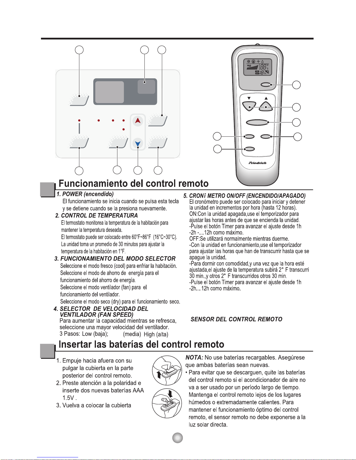
6. AUTO SWING
This button can automatically control the air flow
direction.
7
To receive the signal from remote controller.
dry operation.
(dehumidify operation)
Page 7

6
HSILGNE
VENT
OPEN
Adjusting the Air Flow Direction
Vent Control
For maximum cooling efficiency, CLOSE the vent. This will allow internal air circulation.
OPEN the vent to discharge stale air.
NOTE :
Adjusting the Air Flow Direction
Airflow can be adjusted by changing the direction of the air conditioner's louvers.
• Adjusting Horizontal Air Flow Direction
Adjusting the vertical louvers left and right will
change horizontal airflow.
• Adjusting Vertical Air Flow Direction
Adjusting the horizontal louver up and down will
change vertical airflow. The louver can be
adjusted by pressing in at the top or button of the
horizontal louver.
Adjusting horizontal air flow Adjusting vertical air flow
CLOSE
Part A
Part B
Before using the ventilation feature,
position the lever, as shown. First, pull down
part to horizontal line with part
.
A
B
0
F
P
ower
Mode
T
imer
0n
/0
ff
Fan
Speed
T
emp
Co
ol
Mon
ey
Saver
®
F
an
Only
D
r
y
hr
Au
t
o
Swing
0
F
P
ower
Mode
T
im
er
0n/0ff
Fan
Speed
T
emp
Coo
lMon
ey
Saver
®
Fan
Onl
y
D
ry
hr
Auto
Swing
Page 8

7
Drain pipe
Drain cap
Care and Maintenance
Turn the power off and unplug the power plug before cleaning the air conditioner.
Air Filter
The air filter behind the inlet grille should be checked and cleaned at least once every 2 weeks (or as
necessary) to maintain optimal performance of the air conditioner.
How to remove the air filter
Drainage
The base pan may overflow due to high humidity. To drain
the excess water, remove the drain cap from the back of
the unit and secure the drainpipe. However, excess water may
drip out of the back of the basepan, which is normal operation.
When pressing the drainpipe into place, apply force in the
direction away from the fins to avoid injuring yourself.
1. Open the inlet grille upward by pulling out the bottom of the inlet grille.(a)
2. Remove the air filter from the front grille assembly by pulling the air filter up
slightly.
3.Wash the filter using lukewarm water below104°F(40°
C).(b)
4. Gently shake the excess water from the filter.
When completely dry, replace the filter.
b
Page 9

A
i
r
P
u
r
i
f
i
e
r
Po
w
e
r
T
e
m
p
Mo
de
T
i
m
e
r
F
a
n
S
pe
e
d
A
ot
u
gn
i
w
S
8
HSILGNE
Hardware Location
Product Features
CAUTION
This appliance should be installed in accordance with local and national wiring regulations. This
manual acts as a guide to help to explain product features.
Vertical Air Deflector
(Horizontal Louver)
Horizontal Air Deflector
(Vertical Louver)
Air Discharge
Cabinet
Air Filter
Air Intake(Inlet Grille)
Remote Controller
Front Grill
P
r
ew
o
e
d
o
M
r
e
m
iT
n
0/0f
f
T
p
me
l
o
o
C
y
eno
M
r
e
va
S
®
F
n
a
y
lnO
D
r
y
o
tu
A
g
n
i
w
S
Evaporator
Control Board
Brace
Condenser
Base Pan
Compressor
Power Cord
0
F
P
rew
o
e
d
o
M
re
miT
n0 /0ff
F
n
a
dee
p
S
T pm
e
l
o
o
C
y
e
n
oM
r
ev
a
S
®
F
n
a
yl
n
O
D
ry
rh
ot
uA
gn
i
wS
Page 10

9
ENGLISH
NOTE TO INSTALLER: Leave these
instructions with the air conditioner after
installation is complete.
NOTE TO CONSUMER: Keep this Installation
and Operation Manual for future use.
Important notes:
It is recommended that proper attire be worn
during installation.
For personal safety, this air conditioner must
be properly grounded.
It is important to have the wall outlet and circuit
checked by a qualified electrician if there is any
doubt as to whether a proper ground exists.
CAUTION:
Do not under any circumstances, cut or remove
the third (ground) prong from the power cord.
Do not change the plug on the power cord of
this air conditioner.
Aluminum house wiring may present special
problems ; consult a qualified electrician.
Before You Begin
Read these instructions completely and carefully.
Installation Instructions
❒ Phillips-head screwdriver
❒ Flat-blade screwdriver
❒ Ruler or tape measure
❒ Scissors or knife
❒ Pencil
❒ Level
❒ Hammer
Tools You Will Need
Page 11

10
22" to 36"
Offset
1
/2" to 11/4"
Sill
Exte
rior
Interior wall
20
1
/12" min.
(Without frame curtain)
Stool
15" min
(With frame curtain)
About
1
/2"
"06~"03
Awning
Cooled air
Fence
Over 20"
Heat
radiation
How to Install the Unit
1. To prevent vibration and excess noise,
make sure the unit is installed securely
and firmly.
2. If possible Install the unit where the sunlight
does not shine directly on the unit.
3. The outside of the cabinet must extend
outward for at least 12" and there should
be no obstacles, such as a fence or wall,
within 20" from the back of the cabinet, as
it will prevent heat radiation of the
condenser.
Restriction of outside air will greatly reduce
the cooling efficiency of the air conditioner.
CAUTION: DO NOT cover or block any of the side louvers.
All side louvers of the cabinet must remain
4. Install the unit with a rear, downward slope, so the back is slightly lower than the front
(about 1/4" bubble on a level). This will force condensation to flow to the outside.
5. Install the unit with the bottom about 30"- 60" above the floor level.
Window Requirements
NOTE: All supporting parts should be secured to sturdy wood, masonry, or metal.
• This unit is designed for installation in standard
double hung windows with actual opening widths
from 22" to 36".
• The top and bottom window sash must open
sufficiently to allow a clear vertical opening of 15"
from the bottom of the upper sash to the window
stool.
HSILGNE
exposed and unobstructed to the outside of the structure.
Page 12

Have the following tools available for installation:
* Screwdriver (Slotted and Phillips) * Ruler
* Knife * Hammer
* Pencil * Level
Installation Kit Contents
11
Type F:2EA
(SILL SUPPORT)
Type G:2EA
(BOLT)
Type C:5EA
(SCREW)
Type A:13EA
(SCREW)
Type D:2EA
(NUT)
10mm
16mm
Type H:1EA
(FOAM-STRIP)
Type K:2EA
(FRAME-GUIDE)
Type N:1EA
(DRAIN JOINT PIPE)
Type M:1EA
(FOAM-PE)
Type L:1EA
(WINDOWLOCKINGBRACKET)
16mm
Type B:3EA
(SCREW)
Type E:2EA
(FRAME CURTAIN)
10mm
1
2
3
4
5
6
7
8
9
10
11
12
Page 13

12
HSILGNE
PREPARATION OF CHASSIS
1. Remove the screws which fasten the cabinet
at both sides and at the back.
2. Slide the unit out from the cabinet by gripping
the base pan handle and pulling forward while
bracing the cabinet.
3. Cut the window sash seal to the proper length.
Peel off the backing and attach the Foam-PE to
the underside of the window sash.
4.
5.
6.
Insert the Frame guides into the bottom of the
cabinet.
Insert the Frame Curtain into the
and Frame Guides.
Fasten the curtains to the unit with 8 Type
A screws.
Shipping screws
Foam-PE
Upper guide
Screw
(Type A)
Screw(Type A)
Frame guide
Fig. 1
Fig. 2
Fig. 3
Fig. 4
Suggested Tool Requirements
SCREWDRIVER(+, -), RULER, KNIFE, HAMMER, PENCIL, LEVEL
Upper Guide
0
F
Power
Mo
d
e
T
imer
0n
/0
ff
F
an
S
p
e
e
d
T
e
mp
C
o
o
l
Mo
ney
Sa
ve
r
®
F
a
n
On
l
y
Dr
y
hr
A
u
t
o
S
win
g
0
F
Power
Mod
e
T
i
mer
0n/0
f
f
F
a
n
S
p
e
e
d
T
emp
C
oo
lM
oney
Save
r
®
Fan
On
l
y
D
r
y
hr
A
u
t
o
S
w
ing
(Fig .1)
(Fig .2)
(Fig .3)
(Fig .4)
(Fig .4)
(Fig .4)
1
1
9
Page 14

13
ROODTUOROODNI
Sill Support
NutBolt
ROODTUOROODNI
Cabinet
About
1
/2"
Frame Guide
Screw(Type A)
Upper Guide
Window stool
Front Angle
Window Sash Upper guide
Frame Curtain
Foam-PE
Foam-PE
Cabinet
Fig. 1
Fig. 2
Fig. 3
Fig. 4
Cabinet Installation
1. Open the window. Mark a line on center of the
window stool.
Carefully place the cabinet on the
window stool and align the center mark on the
bottom front with the center line marked in the
window stool. (Fig. 1)
2. Pull the bottom window sash down behind the
Upper Guide until they meet.
NOTE: Do not pull the window sash down so
tightly that the movement of Frame
Curtain is restricted.
3. Loosely assemble the Sill Support using
the parts . (Fig. 3)
4. Select the position that will place the Sill
Support near the outer most point on sill.
(Fig. 4)
NOTE: Be careful when you install the cabinet
(Frame Guides are broken easily).
5. Attach the Sill Support to the cabinet track
hole in relation to the selected position using
2 -type A screws in each support.
( Fig. 4).
(Fig. 2)
11
5
5
6
4
7
6
9
1
6
9
6
Page 15

14
Sash track
Front Angle
About
1
/
2
"
Screw(Type B)
Screw(Type B)
Sill Support
Sill Support
Foam-Strip
Fig. 5
Type C
Fig. 6
Fig. 8
6. The cabinet should be installed with a very slight
tilt (about 1/2") downward toward the outside
(See Fig. 5).
Adjust the bolt and the nut of
Sill Support for balancing the cabinet.
7. Attach the cabinet to the window stool by driving
the screws [Type B: Length 16mm (5/8 inch)
and below.] through the front angle into window
stool.
8. Pull each Frame Curtain to each window
sash track, and repeat step 2.
9. Attach each Frame Curtain to the window
sash using screws (Type C). ( Fig. 6)
CAUTION: Do not drill a hole in the bottom pan.
The unit is designed to operate with
approximately 1/2" of water in bottom
of pan.
There is no need to add water if the
pan is dry.
10. Slide the unit into the cabinet. ( Fig. 7)
CAUTION: For security purposes, reinstall the 2
screws (Type A) at cabinet's side, that
were removed in step 1 on page 12.
11. Cut the Foam-Strip to the proper length
(window width) and wedge between the upper
window sash and the lower window sash.
( Fig. 8)
(Fig. 5)
(Fig. 5)
6
2
6
2
5
2
6
3
5
3
8
8
Fig.7
Screw(Type A)
Screw(Type A)
Power cord
0
F
P
o
w
e
r
M
od
e
T
i
m
e
r
0
n/0
ff
F
a
n
Sp
e
e
d
T
e
m
p
C
o
o
l
M
on
e
y
Save
r
®
F
a
n
O
n
ly
D
r
y
hr
Auto
Sw
i
ng
1
1
Page 16

15
Window locking
bracket
Fig. 9
Fig. 10
12. Attach the Window Locking Bracket with a Type C
screw . ( Fig. 9)
13. Attach the front grille to the cabinet by inserting the
tabs on the grille into the tabs on the front of the
cabinet. Push the grille in until it snaps into place.
(Fig. 10)
14. Pull down the inlet grille and secure it with a Type A
screw through the front grille. ( Fig. 11)
15. Window installation of room air conditioner is now
completed. See ELECTRICAL DATA for
plugging the power cord into the properly
rated electrical outlet.
10
10
3
1
Fig. 11
P
ow
er
Mode
Timer
0n/0
f
f
T
em
p
Co
o
l
Mo
n
ey
S
aver
®
F
an
On
ly
D
r
y
Aut
o
Swing
Page 17

IMPORTANT
IMPORTANT
NOTE:
(cont.)
FINISH THE WALL OPENING
The case may be
in both existing and new construction.
Read completely, then follow step-by-step.
Secure with 14 wood screws anchored at
Ieast an inch into the wall support structure.
Drill pilot holes, if necessary, for
proper installation. If the frame is oversized,
use shims to prevent case distortion.
Caulk all four sides on the outdoor side of
the case to prevent moisture from getting
through to the interior wall. Use of flashing
(drip rail) will further prevent water from
dripping inside the wall and down the
outsida of the building.
NOTE: Obtain all materials locally for
mounting the air conditioner through
the wall.
Through-the-wall installation is not
appropriate if any of the side or top louvers
in the case will be obstructed by the wall.
All side and top louvers in the case must
project on the outdoor side of the wall.
The room side of the case must project
into the room far enough to maximize the
balance of the unit.
The case must be installed level from sideto side and with a slight tilt from front to
rear. Use a level; no more than a 1/2 bubble
will be the correct case slant to the outside.
installed through
the wall
-
-
- -
1
1
D
A
2
Lintel angle is required to supportbricks or
blocks above opening.
Flashing is required and should extend the
length of the opening to ensure no inside
cavity leakage occurs.
Remove the air conditioner from the case.
For specific instruction, refer to the Window
Installation Instructions.
Make certain that a wall receptacle is
available close to the hole location or make
arrangementsto install a receptacle.
Place the case in the wall opening and
Place the air conditioner into the case.
For specific instruction, refer to the Window
Installation Instructions.
place wood support strips between the case
bottom and the flashing on both sides of the
bottom rail. They should be the same height
as the bottom rail and the same length as
the wall opening.
A
B
C
B
Through-the-Wall Installation Instructions-Optional
16
Page 18

17
Troubleshooting Tips
Troubleshooting Tips save time and money! Review the chart below first and you may not need to call for service.
oD oT tahWsesuaC elbissoPmelborP
■ The air conditioner is
unplugged.
■ The fuse is blown/circuit
breaker is tripped.
■ Power failure.
■ The current interrupter
device was tripped on
the power cord.
■ Airflow is restricted.
■ The THERMOSTAT may
not be set high enough.
■ The air filter is dirty.
■ The room may have been
hot.
■ Cold air is escaping.
■ Cooling coils have iced up.
■ Ice blocks the air flow and
stops the air conditioner
from cooling the room.
• Make sure the air conditioner plug is pushed
completely into the outlet.
• Check the house fuse/circuit breaker box and
replace the fuse or reset the breaker.
• If power failure occurs, turn the mode control to Off.
When power is restored, wait 3 minutes to restart the
air conditioner to prevent tripping of the compressor
overload.
• Press the RESET button located on the power
cord plug. If the RESET button will not stay eng
aged, discontinue use of the air conditioner and
contact a qualified service technician.
• Make sure there are no curtains, blinds, or furniture
blocking the front of the air conditioner.
• Push temperature setting button to coolest
temperature setting of 60°F.
• Clean the filter at least every 2 weeks.
See the operating instructions section.
• When the air conditioner is first turned on you need
to allow time for the room to cool down.
• Check for open furnace floor registers and cold air
returns.
• Set the air conditioner's vent to the closed position.
• See Air Conditioner Freezing Up below.
• Set the mode control on high fan until the ice thaws
out. This may indicate a bigger problem.
Air conditioner
does not start
Air conditioner
does not cool as it
should
Air conditioner
freezing up
Normal Operation
• You may hear a pinging noise caused by water being picked up and thrown against the condenser
on rainy days or when the humidity is high. This design feature helps remove moisture and improve
efficiency.
• You may hear the thermostat click when the compressor cycles on and off.
• Water will collect in the base pan during high humidity or on rainy days. The water may overflow and
drip from the outdoor side of the unit.
• The fan may run even when the compressor does not.
• Your air conditioner is designed to cool in warm weather when the outside temperature is above
60°F(16°C) and below 115°F(46°C).
Abnormal Operation
Page 19

18
ENGLISH
FRIEDRICH AIR CONDITIONING CO.
Post Office Box 1540 • San Antonio, Texas 78295-1540
(210) 357-4400 • FAX (210) 357-4490
ROOM AIR CONDITIONERS
LIMITED WARRANTY
FIRST YEAR
SECOND THROUGH FIFTH YEAR
Revised 11/07
1. Air filters or fuses.
2. Products on which the model and serial numbers have been removed.
3. Products which have defects or damage which results from improper installation, wiring, electrical current characteristics, or
maintenance; or caused by accident, misuse or abuse, fire, flood, alterations and/or misapplication of the product and/or units
installed in a corrosive atmosphere, default or delay in performance caused by war, government restrictions or restraints, strikes,
material shortages beyond the control of FRIEDRICH, or acts of God.
ANY PART: If any part supplied by FRIEDRICH fails because of a defect in workmanship or material within twelve months from date of
original purchase, FRIEDRICH will repair the product at no charge, provided room air conditioner is reasonably accessible for service.
Any additional labor cost for removing inaccessible units and/or charges for mileage related to travel by a Service Agency that exceeds
25 miles one way will be the responsibility of the owner. This remedy is expressly agreed to be the exclusive remedy within twelve
months from the date of the original purchase.
SEALED REFRIGERANT SYSTEM: If the sealed refrigeration system (defined for this purpose as the compressor, condenser coil,
evaporator coil, reversing valve, check valve, capillary, filter drier, and all interconnecting tubing) supplied by FRIEDRICH in your Room
Air Conditioner fails because of a defect in workmanship or material within sixty months from date of purchase, FRIEDRICH will pay a
labor allowance and parts necessary to repair the Sealed Refrigeration System; PROVIDED FRIEDRICH will not pay the cost of diagnosis
of the problem, removal, freight charges and transportation of the air conditioner to and from the Service Agency, and the reinstallation
charges associated with repair of the Sealed Refrigeration System. All such cost will be the sole responsibility of the owner. This remedy
is expressly agreed to be the exclusive remedy within sixty months from the date of the original purchase.
APPLICABILITY AND LIMITATIONS:
This warranty is applicable only to units retained within the Fifty States of the U.S.A., District of
Columbia, and Canada. This warranty is not applicable to:
OBTAINING WARRANTY PERFORMANCE: Service will be provided by the FRIEDRICH Authorized Dealer or Service Organization
in your area. They are listed in the Yellow Pages.If assistance is required in obtaining warranty performance, write to: Room Air Conditioner
Service Manager, Friedrich Air Conditioning Co., P.O. Box 1540, San Antonio, TX 78295-1540.
LIMITATIONS: THIS WARRANTY IS GIVEN IN LIEU OF ALL OTHER WARRANTIES. Anything in the warranty notwithstanding,
ANY IMPLIED WARRANTIES OF FITNESS FOR PARTICULAR PURPOSE AND/OR MERCHANTABILITY SHALL BE LIMITED TO
THE DURATION OF THIS EXPRESS WARRANTY. MANUFACTURER EXPRESSLY DISCLAIMS AND EXCLUDES ANY LIABILITY
FOR CONSEQUENTIAL OR INCIDENTAL DAMAGE FOR BREACH OF ANY EXPRESSED OR IMPLIED WARRANTY.
NOTE:
Some states do not allow limitations on how long an implied warranty lasts,or do not allow the limitation or exclusion of consequential
or incidental damages,so the foregoing exclusions and limitations may not apply to you.
OTHER: This warranty gives you specific legal rights, and you may also have other rights which vary from state to state.
PROOF OF PURCHASE: Owner must provide proof of purchase in order to receive any warranty related services.
All service calls for explaining the operation of this product will be the sole responsibility of the consumer.
All warranty service must be provided by an Authorized FRIEDRICH Service Agency, unless authorized by FRIEDRICH prior to
repairs being made.
In case of questions regarding the provisions of this warranty, the English version will govern.
Page 20

FRANÇAIS
920-200-00 (11/07)
Manuel d'utilisation
et d'installation
de votre climatiseur de pièce
NUMÉRO DU MODÈLE NUMÉRO DE SÉRIE DATE D'ACHAT
Enregistrement de votre climatiseur de pièce
Vous trouverez l'information concernant l'appareil sur la plaque signalétique
située sur le côté de l'appareil, près du panneau de commande. Veuillez
remplir et poster la carte d'enregistrement fournie avec l'appareil ou
enregistrez-vous en ligne à www.friedrich.com (USA uniquement). Veuillez
consigner l'information à l'emplacement ci-dessous pour référence ultérieure.
CP Line
CP06115 Volts
CP08
0
F
Power
Mode
Timer
0n/0ff
Fan
Speed
Temp
CoolMoney
Saver
®
Fan
Only
Dry
hr
Auto
Swing
0
F
Power
Mode
Timer
0n/0ff
Fan
Speed
Temp
CoolMoney
Saver
®
Fan
Only
Dry
hr
Auto
Swing
Page 21

Félicitations!
Merci d'avoir choisi Friedrich.
Votre unité Friedrich est conçue pour vous
offrir le confort et le silence maximums.
Table des matières
Introduction ..................................................................................2
Mesures de sécurité.....................................................................3
Fonctionnement de la télécommande........................................5
Réglage de l'orientation du débit d'air .......................................6
Soins et entretien.........................................................................7
Installation du matériel................................................................8
Guide d'installation......................................................................9
Problèmes fréquents et solutions ............................................17
Garantie.......................................................................................18
Page 22

2
FRANÇAIS
Introduction
Avant d'utiliser votre appareil
Assurez-vous que votre câblage électrique est conforme aux normes de
fonctionnement de l'appareil.
Si votre système électrique comporte des fusibles, veillez qu'ils soient de type temporisé. Avant d'installer ou
de déplacer l'appareil, veillez que l'intensité de courant du disjoncteur ou du fusible temporisé n'excède pas
l'intensité de courant spécifiée à la figure 1.
N'UTILISEZ JAMAIS un fil de rallonge.
Contrairement au cordon d'alimentation fourni avec l'appareil, le fil de rallonge n'acheminera pas le courant
d'alimentation approprié au bon fonctionnement de l'appareil.
Veillez à ce que la prise murale soit compatible avec la fiche du cordon
d'alimentation de l'appareil.
Cela assure la mise à la terre appropriée. Si vous possédez un réceptacle à deux broches, vous devrez le
remplacer par un réceptacle conforme à tous les codes et règlements nationaux ou municipaux. Vous devez
utiliser la fiche à trois broches fournie avec votre climatiseur.
Figure 1
Pour obtenir le meilleur rendement énergétique et de refroidissement
Maintenez le filtre propre
Afin de maintenir le rendement de votre climatiseur à son meilleur niveau, nettoyez régulièrement le filtre.
Reportez-vous à la page 7 pour les instructions de dépose et de nettoyage du filtre.
Veillez à la présence d'une circulation d'air appropriée.
Assurez-vous que l'air circule librement vers et en provenance de l'appareil. Votre climatiseur aspire l'air à
sa surface inférieure et l'évacue à sa surface supérieure. La circulation d'air est un facteur important au
bon fonctionnement de l'appareil. La libre circulation de l'air est également importante
pour la portion de l'appareil située à l'extérieur de l'immeuble.
Emplacement de l'appareil
Votre climatiseur fonctionnera plus efficacement si vous l'installez dans une fenêtre ou dans un mur
situé à l'ombre d'un arbre ou d'un autre immeuble. L'utilisation de rideaux ou stores du côté ensoleillé de
l'immeuble améliorera également le rendement de l'appareil.
Isolation
Une bonne isolation permettra de maintenir le niveau de confort souhaité. Les portes devraient
comporter un calfeutrage adéquat. Veillez à bien calfeutrer le périmètre des portes et fenêtres.
MODÈLE
CP06 CP08
AMP VOLT
NO. NEMA
(National Electrical Manufacturers Association)
15 125 5-15P
VALEUR NOMINALE OU
TEMPORISATION DU
CIRCUIT FUSIBLE
TYPE DE FICHE
115V~ 230V~
Le cordon d'alimentation peut inclure un
dispositif de coupure. Un bouton Test et un
bouton Reset (rétablir) sont fournis dans le
boîtier de la fiche. Ce dispositif doit être
périodiquement testé en appuyant d'abord
sur le bouton TEST et ensuite sur le bouton
RESET. Si le bouton TEST ne déclenche
pas ou que le bouton RESET ne reste pas
activé, veuillez suspendre l'utilisation du
climatiseur et contacter un technicien
AVIS
Une installation électrique en aluminium peut poser des
problèmes particuliers. Consultez un électricien qualifié.
Page 23

3
Mesures de Sécurité
Pour éviter des accidents corporels ou des dommages matériels, suivez ces instructions.
■
Un mauvais fonctionnement dû à l’ignorance de ces instructions peut provoquer des préjudices corporels
ou des dommages.
AVERTISSEMENT
AVERTISSEMENT
Ce symbole signale un risque de blessure grave, voire mortelle.
ATTENTION
Ce symbole signale un risque limité aux dommages matériels.
■Les significations respectives des symboles utilisés dans ce manuel sont indiquées ci-dessous.
Ne faites jamais cela
Faites toujours cela
Veillez à brancher
correctement votre appareil
• Tout mauvais branchement peut
entraîner une surchauffe de votre
appareil et causer électrocution
ou incendie.
Veuillez ne pas mettre en
marche ou éteindre votre
appareil en branchant ou
débranchant votre appareil
• Ceci provoquera une surchauffe
et un risque d'électrocution ou
d'incendie.
Evitez d'endommager le
cordon d'alimentation
électrique ou d'en utiliser un
non-agéé
• Ceci pourrait causer
électrocution ou incendie.
Ne modifiez pas la longueur du
cordon d'alimentation et ne
branchez pas votre climatiseur
en commun avec d'autres
appareils sur la même prise
• Ceci pourrait provoquer un
électrique ou un incendie, dû à
une surchauffe.
Ne faites pas fonctionner
l'appareil les mains
mouillées.
• II y a risque d'électrocution.
Ne dirigez pas directement le
flux d’air sur les occupants
de la pièce.
• Ceci pourrait mener au problème
de santé.
Page 24

4
ATTENTION
Lorsque le filtre à air doit
être retiré, ne pas toucher les
parties métalliques de
l'appareil.
• Vous risquez de vous blesser.
Ne pas nettoyer le
climatiseur avec de l'eau.
• L'eau peut s'infiltrer dans
l'appareil et affecter l'isolement.
Cela peut également provoquer
un choc électrique.
Quand l'unité devrait être
nettoyée, change l'unité de, et le
débrancher.
• Le ventilateur de refroidissement
tournant à grande vitesse dans
l'appareil, cela peut provoquer un
accident.
Ne pas opérer l'unité sans le
filtre à air ou quand le
grillage frontal a été enlevé.
• De la poussière pourrait
s'accumuler sur l'échangeur
thermique.
Ne pas placer une plante
d'intérieur ou un animal
domestique près de l'appareil
en risquant de l'exposer
directement à l'air froid.
• Ce produit peut blesser les
animaux ou abimer les plantes.
Ne pas se servir de l'appareil
à des fins spéciales.
•
Le climatiseur ne doit pas être utilisé pour
protéger certains appareils de précision, des
aliments, des animaux, des plantes et des
objets d'art. La qualité risque d'en souffrir.
Ne pas actionner les
dispositifs de commande les
mains mouillées.
• Il y a risque de choc électrique.
Ne pas utiliser d'insecticide à
proximité de l'appareil ni de
produits inflammables.
• L'appareil risque de prendre feu
ou le coffret risque d'être
déformé.
BORDS POINTUS!
Les bords du cas peuvent être
pointus!
• Faites attention en manipulant le boîtier.
Saisissez le boîtier fermement et ne le
laissez pas glisser tout en le tenant.
•
Employez les gants lourds pour manipuler
le boîtier au besoin.
• Ne laissez pas
le boîtier
glisser contre
votre peau!
FRANÇAIS
Page 25

FRANÇAIS
5
Fonctionnement de la télécommande CP
0
F
Power
Mode
Timer
0n/0ff
Fan
Speed
Temp
CoolMoney
Saver
®
Fan
Only
Dry
hr
Auto
Swing
1
3
2
4
6
5
7
Ai r
P ur ifi er
Po we r
Tem p
Mod e
Ti me r
A
S wi ng
Fa n S pee d
1
2
4
3
5
Auto
Swing
6
7.
6.
OSCILLATION AUTOMATIQUE
Ce bouton peut contrôler automatiquement la
direction de l'air.
Pour recevoir le signal de la télécommande
Page 26

6
FERMÉ VENTILATION OUVERT
Réglage de l'orientation du débit d'air
Commande de l’orifice de ventilation
Pour une efficacité maximum du refroidissement, fermez l'ORIFICE DE VENTILATION. Ceci activera
la circulation de l'air de la pièce. OUVREZ l'orifice de ventilation afin d'évacuer l'air vicié.
NOTE:
Réglage de l’orientation du débit d’air
Vous pouvez régler le débit d'air en changeant l'orientation des volets du climatiseur.
•
Réglage de l'orientation horizontale du débit d'air
Le réglage des volets verticaux vers la gauche et
la droite changera l'orientation du débit d'air
horizontal.
•
Réglage de l'orientation verticale du débit d'air
Quand vous réglez le louvre horizontal vers le
haut et vers le bas, vous changez le flux d’air
vertical. Le louvre peut être réglé en appuyant
sur le sommet ou le bas du louvre horizontal.
Réglage du débit d'air horizontal Réglage du débit d'air vertical
FRANÇAIS
Part A
Part B
La poignée de contrôle du ventilateur doit être
redressée avant que la partie décorative frontale soit
fixée. Tirer la partie à aligner avec la partie
.
A
B
0
F
Power
M
ode
T
imer
0n
/0
ff
Fan
Speed
T
emp
Co
olMoney
Saver
®
F
an
Only
D
r
y
hr
Au
to
Swing
0
F
P
ower
Mode
T
i
m
er
0n
/0
f
f
F
an
Speed
Temp
Co
o
lMoney
Saver
®
F
an
Only
D
r
y
hr
Aut
o
Swing
Page 27

7
Tuyau de
drainage
Bouchon de drainage
Soins et entretien
Avant de nettoyer le climatiseur, éteignez-le et débranchez la fiche d'alimentation.
Filtre à air
Afin de maintenir l'efficacité du climatiseur à son meilleur niveau, vous devriez nettoyer le filtre à air,
situé en arrière de la grille de prise d'air, au moins à toutes les deux semaines (ou au besoin).
Comment retirer le filtre à air
Drainage
Le réceptacle d'eau peut déborder selon le taux
d'humidité. Pour évacuer l'excédent d'eau, retirez le
bouchon de drainage situé à l'arrière de l'appareil et
installez le tuyau de drainage.
En installant le tuyau de drainage, appliquez la pression
dans le sens opposé des ailettes de refroidissement de
manière à ne pas vous blesser.
FRANÇAIS
b
1. Ouvrez la grille d'admission vers le haut en retirant le fond de la grille d'admission.(a)
2. Enlevez le filtre à air de la grile d’assemblage avant en levant le filtre à air vers le haut
ou bas légèrement.
3. Lavez le filtre en utilisant de l’eau tiède au dessus
104°F(40° C).(b)
4. Secouez doucement l'exès d'eau du filtre complètement. Si le filtre est complètement
sec,remplacez -le.
Page 28

8
Installation du matériel
Caractéristiques particulières de l’appareil
ATTENTION
Cet appareil doit être installé en fonction des normes électriques locales, régionales et
nationales. L'illustration suivante sert à situer les différents éléments de l'appareil.
A
i
r
P
u
r
if
i
e
r
Po
we
r
T
e
m
p
Mod
e
Ti
m
e
r
Fan
S
p
e
e
d
A
o
t
u
g
ni
w
S
P
re
w
o
e
d
oM
r
e
m
iT
n
0
/0ff
T
p
me
l
oo
Cy
e
n
o
M
r
e
v
a
S
®
F
n
a
y
l
n
O
D
r
y
otu
A
g
n
i
w
S
0
F
P r
e
w
o
ed
o
M
re
m
i
T
n
0
/0
f
f
F
n
a
d
ee
pS
T pm
e
loo
C
y
e
n
o
M
r
e
v
aS
®
F
na
y
l
nO
D
r
y
r
h
ot
u
A
gni
w
S
DEFLECTOR DE
AIRE HORIZONTAL
(VENTANILLAS
HORIZONTALES)
DEFLECTOR HORIZONTAL
DE AIRE
(VENTANILLAS
VERTICALES)
SALIDA DE AIRE
CONTROL
REMOTO
RECOLECTOR
DE AIRE
FILTRO DE
AIRE
REJILLA
FRONTAL
GABINETE
SUSPENSORES
CONDENSADOR
BANDEJA
COMPRESOR
CABLE DE CONEXIÓN ELÉCTRICA
DE CONTROL
PANEL
EVAPORADOR
Page 29

9
Page 30

10
22" à 36"
Décalage
1
/2" to 11/4"
Seuil
Extérieur
Mur intérieur
20
1
/
12
" min.
(Sans volets d'étanchéité)
Rebord
15"min.
(volet d'étanchéité inclus)
Environ 1/2" (1,27 cm)
30"~60"
Auvent
Air refroidi
Clôture
20" (51 cm) ou plus
Radiation
de chaleur
Installation de l’appareil
1. Installez l'appareil solidement et
sécuritairement de manière à prévenir la
présence de vibrations et bruits.
2.
3. Le boîtier doit sortir d'au moins 12" à
l'extérieur et aucun obstacle du genre
clôture ou mur doit se situer à moins de
20" de l'arrière du boîtier car cela nuira à
la radiation de chaleur du condenseur. La
capacité de refroidissement du climatiseur
sera sérieusement affectée par une
restriction d'alimentation d'air extérieur.
MISE EN GARDE : Attention : tous les louvres latéraux du boîtier doivent restés ouverts et non
bouchés vers l’extérieur de la structure.
4. Installez l’unité avec une inclinaison arrière vers le bas pour que l’arrière soit légèrement plus bas
que l’avant d’environ.
Cela force la condensation à couler vers l’extérieur.
5. Installez l'appareil de manière à ce que sa surface inférieure se situe entre 30" et 60" (76 et 152 cm)
au-desssus du niveau du plancher.
Dimensions de fenêtre minimales
NOTE : Tous les éléments d'installation doivent être fixés à du bois, de la maçonnerie ou du métal
sain et solide.
• Cet appareil est conçu pour installation
dans des fenêtres à guillotine normales de
largeur variant entre 22" et 36".
• Les châssis supérieur et inférieur de la
fenêtre doivent offrir une ouverture verticale
d'au moins 15" entre le bas du châssis
supérieur et le rebord de la fenêtre.
32
FRANÇAIS
Page 31

11
Contenu du nécessaire d’installation
10mm
16mm
16mm
10mm
Tipo A:13 EA
(TORNILLO)
Tipo B:3 EA
(TORNILLO)
Tipo C:5 EA
(TORNILLO)
Tipo D:2 EA
(TUERCA)
Tipo E:2 EA
(PANEL GUÍA)
Tipo F:2 EA
(SOPORTE DE ALFÉIZAR)
Tipo G:2 EA
(TORNILLO)
Tipo H:1 EA
(TIRA DE GOMA)
Tipo K:2 EA
(GUÍA MARCO)
(CHAPADE SOPORTEPARALAVENTANA)
Tipo L:1 EA
Tipo M:1 EA
(BANDA ADHESIVA)
Tipo N:1 EA
(TAPA DEL DESAGÜE)
Para la instalación debería tener a disposición los instrumentos siguientes:
* Destornillador (Estrella y Phillips) * Regla
* Cucjillo
* Martillo
* Lápiz Nivel
1
2
3
4
5
6
7
8
9
10
11
12
Page 32

12
Outils recommandés
TOURNEVIS (+, -), RÈGLE, COUTEAU, MARTEAU, CRAYON, NIVEAU
PRÉPARATION DU CADRE
1. Déposez les vis situées de part et d'autre et à l'arrière du
boîtier.
2. Tout en retenant le boîtier, glissez l'appareil hors du
boîtier en tirant vers l'avant sur la poignée du réceptacle
d'eau.
6. Fixez les volets d'étanchéité à l'appareil à l'aide de quatre
vis de type A
.
(Fig 1)
3.
VIS (Type A)
Fig. 1
Fig. 2
Fig. 3
Fig. 4
0
F
4
Vis
d'expédition
(FENÊTRE)
RAIL DE GUIDAGE SUP
RIEUR
SIV
(type A)
DISPOSITIF DE GUIDAGE DU CADRE
(Fig 2)
5.
Insérez les volets d'étanchéité
dans le rail de guidage
supérieur et dans les dispositifs de guidage du cadre.
(Fig 4)
(Fig 4)
(Fig 4)
Corte la banda adhesiva
ycoló quela del ancho de la
Remueva el plástico de la banda adhesiva
y colóquela en la parte superior de el
marco inferior de la ventana.
ventana.
1
1
9
FRANÇAIS
0
F
P
ower
Mo
d
e
T
i
mer
0n
/0
ff
F
a
n
S
p
e
e
d
T
e
mp
C
o
o
l
M
o
ney
S
a
v
e
r
®
F
an
Onl
y
Dr
y
hr
A
u
t
o
S
w
in
g
0
F
P
ower
Mo
d
e
T
i
mer
0n
/0f
f
F
a
n
S
p
e
e
d
T
e
mp
C
o
o
l
M
o
ney
S
a
v
e
r
®
F
an
Onl
y
Dr
y
hr
A
u
t
o
S
w
in
g
Page 33

13
INTÉ TXERUEIR ÉRIEUR
Support de seuil
ÉcrouBoulon
INTÉ TXERUEIR ÉRIEUR
Boîtier
Environ 1/2" (1,27 cm)
Dispositif de
guidage de cadre
Vis (Type A)
Rail de guidage
supérieur
Rebord de fenêtre
Angle avant
Châssis de fenêtre
Rail de guidage supérieur
Volet d'étanchéité
Joint d'étanchéité
en mousse
Joint d'étanchéité
en mousse
Boîtier
Fig. 1
Fig. 2
Fig. 3
Fig. 4
Installation du boîtier
1. Ouvrez la fenêtre. Tracez une ligne au centre
du rebord de fenêtre.
Placez le boîtier soigneusement sur le rebord
de fenêtre et alignez le repère central de sa
portion inférieure avant avec la ligne tracée
sur le rebord de fenêtre.
2. Abaissez le châssis inférieur à l'arrière du rail
de guidage supérieur jusqu'à ce qu'ils fassent
NOTE: Ne serrez pas le châssis de fenêtre au
point où cela nuira au mouvement des
volets d'étanchéité.
3. Assemblez le support de seuil à l'aide des
pièces illustrées dans la fig. 3 mais ne les
serrez pas.
(Fig. 3)
4. Choisissez l'emplacement qui situera le
support de seuil à l'emplacement le plus à
l'extérieur du seuil
(Fig. 4)
.
NOTE : Installez le boîtier avec précaution
(les dispositifs de guidage de cadre
peuvent briser).
5.
Fixez les supports de seuil aux orifices de
guidage du boîtier, en fonction de
l'emplacement sélectionné, à l'aide de 2 vis de
type A pour chaque support
(Fig. 4).
(Fig. 1)
(Fig. 2)
11
5
7
4
6
9
1
5
6
6
9
6
Page 34

14
Coulisse
de chassis
Angle avant
Environ
1
/
2
"
Vis (Type B)
Vis (Type B)
Support de seuil
Support de seuil
Bande
en mousse
Fig. 5
Vis C
Fig. 6
Fig. 8
6. Installez le boîtier avec une inclinaison
d'environ 1/2" (1,27 cm) vers l'extérieur
(Voyez la fig. 5). Réglez l'écrou et le boulon
des supports de seuil de manière à
équilibrer le boîtier.
7. Fixez le boîtier au rebord de fenêtre à l'aide de
vis de type B (16 mm [5/5"] de long)
passant à travers de l'angle avant du boîtier et
se logeant dans le rebord de fenêtre.
8. Tirez chaque volet d'étanchéité entièrement
contre chaque coulisse de châssis et répétez
l'étape 2.
9. Fixez chaque volet d'étanchéité à la
coulisse de châssis à l'aide de vis de typeC.
MISE EN GARDE : Ne percez pas de trous dans
le réceptacle d'eau. L'appareil est conçu pour
fonctionner avec environ 1/2" (1,27 cm) d'eau
présent dans le réceptacle d'eau. S'il n'y a pas
d'eau dans le réceptacle, il n'est pas nécessaire
d'en ajouter.
10. Glissez l'appareil dans le boîtier.
(Fig. 7)
ATTENTION : Pour votre sécurité, réinstallez le
2 (type A) qui avait été enlevé à
l’étape 1 de la page 12, sur le
côté du boîtier.
11. Coupez la bande en mousse
à la longueur
appropriée et insérez-la entre les châssis
supérieur et inférieur de la fenêtre.
(Fig. 6)
(Fig. 5)
(Fig. 8)
Fig.7
0
F
P
o
w
e
r
Mo
d
e
T
i
m
e
r
0
n
/0
f
f
F
a
n
Sp
e
e
d
T
e
mp
C
o
o
l
M
o
n
ey
Sav
e
r
®
F
a
n
O
n
ly
Dr
y
h
r
Auto
Sw
i
n
g
Cordon
d'alimentation
Vis (Type A)
Vis (Type A)
6
2
2
6
1
1
8
6
2
5
5
3
FRANÇAIS
Page 35

15
Fig. 9
Fig. 10
Étrier de verrouillage
de fenêtre
12. Fixez l'étrier de verrouillage de fenêtre à l'aide d'une
vis de type C
13. Fixez la grille avant au boîtier en en insérant les
languettes de la grille dans les encoches situées à
l'avant du boîtier. Poussez la grille jusqu'à ce que vous
l'entendiez cliquer en place.
(Fig. 10)
14. Abaissez la grille de prise d'air et et fixez-la à l'aide
d'une vis de Type A passant à travers de la grille.
15. L'installation du climatiseur de pièce est maintenant
complétée. Pour les détails de branchement du
cordon d'alimentation à une prise de courant murale,
veuillez vous reporter à SPÉCIFICATIONS
ÉLECTRIQUES.
FRANÇAIS
(Fig. 9)
(Fig. 11)
Fig. 11
P
o
we
r
Mode
T
imer
0n/0
ff
T
em
p
Co
o
l
Money
Sav
er
®
F
an
On
l
y
D
r
y
Au
t
o
Swin
g
10
10
3
Page 36

1
1
D
A
2
A
B
B
16
Installation sur le mur - Instruction facultative
La boîte cas peut être installé sur le mur dans
la construction tant existante que nouvelle.
Lisez complètement, puis suivez étape par
étape.
NOTE: Obtenez tous les matériaux localement
pour monter le climatiseur à travers le mur.
IMPORTANT(cont.)
A bloqué avec 14 vis en bois au moins a
ancré dans la structure de support mural.
NOTE : Percez les trous pilotes, si nécessaire,
pour l'installation appropriée.
Si le cadre est surdimensionné, utilisez les
IMPORTANT
L'installation sur le mur n'est pas appropriée si
un des côtés ou la plus haute lucarne de boîte
est obstrué par le mur.
Tous les côtés et le plus haute lucarne de
boîte doivent projecter sur le côté extérieur du
mur.
Le côté vers la salle de boîte doit projecter
dans la salle assez lointaine pour maximiser
l'équilibre de l'unité.
La boîte doit être installée de niveau d'une
inclinaison verticale et avec légère d'avant à
rear. Use un niveau ;
L'angle de linteau est exigé pour soutenir des
briques ou des blocs au-dessus de l'ouverture.
Le clignotant est exigé et devrait prolonger la
longueur de l'ouverture pour ne pas assurer la
fuite intérieure de cavité se produit.
Un enlèvement le climatiseur de la boîte.
Pour l'instruction spécifique, référez-vous aux
instructions d'Installaion de fenêtre
Assurez-vous qu'une prise murale est
disponible près de l'endroit de trou ou prenez
les arrangements pour installer un receptacle
Placez le cas dans l'ouverture de mur et les
bandes en bois de soutien d'endroit entre le
fond de cas et le clignotant des deux côtés du
fond rail. Ils devraient être la même taille que
le rail inférieur et la même longueur que
l'ouverture de mur.
FINISSEZ L'OUVERTURE DE MUR
Calfeutrez quatre côtés du côté extérieur du
cas pour empêcher l'humidité d'obtenir à
travers au mur intérieur.
Utilisation du clignotant (le rail)will
d'égouttement empêchent plus loin l'eau de
s'égoutter à l'intérieur du mur et avalent
l'extérieur du bâtiment.
placent le climatiseur dans le cas.
Pour l'instruction spécifique, référez-vous aux
instructions d'installation de fenêtre.
Angle de linteau
Calfeutrage
DEHORS
Le louvers
(top
et les côtés
d'air doivent
projeter du côté
extérieurdu mur)
Remplisseur et caulking
bove en bois et au-
dessous du clignotant)
Clignotant
(rail d'égouttement)
Clignotant
(rail d'égouttement)
Ligne de plâtre
du molding
(ifd'équilibre désir
Rail inférieur
À L'INTÉRIEUR
Rail inférieur
bois Soufien Bandes
FRANÇAIS
Page 37

e
17
Page 38

18
FRIEDRICH AIR CONDITIONING CO.
Post Office Box 1540 • San Antonio, Texas 78295-1540
(210) 357-4400 • FAX (210) 357-4490
Garantie limitée – Climatiseurs Friedrich
GARANTIE LIMITÉE -PREMIÈRE ANNÉE
GARANTIE LIMITÉE -DEUXIÈME À CINQUIÈME ANNÉE
Revised 11/07
TOUTES LES PIÈCES - Si, dans les 12 mois suivant la date d’achat initial, une pièce fournie par FRIEDRICH est défectueuse à cause
d’un défaut de main d’oeuvre ou de matériel, FRIEDRICH réparera le produit gratuitement, pourvu qu’il soit raisonnablement facile
d’obtenir accès au climatiseur pour le réparer.Toute main d ’oeuvre nécessaire pour déposer des appareils d ’accès difficile et/ou les frais
de déplacement (kilométrage) par le centre de réparation, au delà de 25 miles (40km) dans une seule direction, sont la responsabilité do
propriétaire. Ce remede est e xpressément accepté comme le seul reméde dans les 12 mois suivant la date d’achat initial.
SYSTEME DE RÉFRIGÉRATION ÉTANCHE - Si le système de réfrigération étanche (dans le cadre de cette garantie, défini comme le
compresseur, le serpentin de condenseur, le serpentin d’évaporateur, la vanne d’inversion, le clapet de non-retour, le tube capillaire, le
filtre-déshydrateur et tous leurs tubes de raccordement) faisant partie du climatiseur FRIEDRICH est défectueux à cause d’un défaut de
main d’oeuvre ou de matériau dans les 60 mois à compter de la date d’achat initial, FRIEDRICH paiera une allocation pour les frais de
main d’oeuvre et les pièces nécessaires pour réparer le système de réfrigération étanche. FRIEDRICH ne paiera pas pour les frais de
diagnostic du problème,de dépose, de transport du climatiseur jusqu’au centre de réparation et de retour ni les frais de repose associés
à la réparation du système de réfrigération étanche. Tous ces frais sont à la charge du propriétaire. Ce remede est expressément accepté
comme le seul reméde dans les 60 mois suivant la date d’achat initial.
CONDITIONS D ’APPLICATION ET LIMITATIONS - Cette garantie s’applique à tous les appareils vendus au détail aux États-Unis, dans
le District de Colombia et au Canada. Cette garantie ne s’applique pas :
OBTENTION DE RÉPARATION SOUS GARANTIE - Le service sera fourni par un distributeur agréé par FRIEDRICH ou un centre de
réparation dans la région. Ils sont indiqués dans les Pages Jaunes. S’il faut de l’assistance pour obtenir des réparations sous garantie,
écrire à Room Air Conditioner Service Manager, Friedrich Air Conditioning Co., P.O. Box 1540, San Antonio, Texas 78295-1540.
LIMITATIONS - CETTE GARANTIE A ÉTÉ DONNÉE EN REMPLACEMENT DE TOUTE AUTRE GARANTIE. Indépendamment de
cette garantie, TOUTE GARANTIE SOUS-ENTENDUE D’APPLICATION POUR UN BUT PARTICULIER ET/OU DE VENDABILITÉ
EST LIMITÉE À LA DURÉE DE LA GARANTIE EXPRESSE. LE FABRICANT SPÉCIFIQUEMENT DÉCLINE ET REFUSE TOUTE
RESPONSABILITÉ POUR LES DOMMAGES INDIRECTS OU SECONDAIRES POUR INEXÉCUTION DE TOUTE GARANTIE EXPRESSE OU SOUS-ENTENDUE.
REMARQUE - Certaines provinces ne permettent pas les limitations sur la longueur de la garantie sous-entendue ou ne permettent pas
la limitation ni l’exclusion des dommages indirects ou secondaires, il est donc possible que ces exclusions et limitations ne s’appliquent
pas à un cas spécifique.
AUTRE - Cette garantie donne des droits spécifiques et il est possible que le propriétaire ait d’autres droits qui varient d’une province à
l’autre.
PREUVE D’ACHAT - Le propriétaire doit fournir la preuve d’achat pour pouvoir recevoir des services sous garantie.
Tous les appels pour expliquer le fonctionnement de ce produit sont à la charge du consommateur.
Toute réparation sous garantie doit être faite par un agent de réparation agréé par FRIEDRICH, sauf en cas d’autorisation préalable par
FRIEDRICH.
En cas de question concernant les clauses de cette garantie,la version en anglais a priorité.
1. aux filtres à air ni aux fusibles ;
2. aux produits dont le numéro de modèle et le numéro de série ont été enlevés ;
3. aux produits dont les défauts ou dégâts ont été causés par une mauvaise installation, un mauvais câblage, l’alimentation avec une
mauvaise tension ou par un mauvais entretien ; ni causés par un accident, une mauvaise utilisation ou des abus, un incendie, des
inondations, des modifications et/ou une mauvaise application du produit et/ou des appareils installés dans une atmosphère
corrosive, problèmes ou délais de réparation causés par actes de guerre, des restrictions ou limitations par le gouvernement, des
grèves, des manquements de matériel en dehors du contrôle de FRIEDRICH ou par des cas de force majeure.
FRANÇAIS
Page 39

ESPAÑOL
CP Lines
920-200-00 (11/07)
Acondicionador de aire
para habitación
Manual de Instalación y
NÚMERO DE MODELO NÚMERO DE SERIE FECHA DE COMPRA
Registrar su acondicionador
de aire para habitación
Model information can be found on the name plate located on the
La información sobre el modelo puede hallarse en la placa ubicada en el
costado de la unidad más cercana al panel de control. Complete y en envíe por
correo la tarjeta de registro de propietario que se entrega con este producto, o
bien regístrese por Internet en www.friedrich.com (sólo para EE.UU.) Para su
conveniencia en el futuro, registre aquí la información sobre su modelo.
CP06 CP08115 Volts
0
F
Power
Mode
Timer
0n/0ff
Fan
Speed
Temp
CoolMoney
Saver
®
Fan
Only
Dry
hr
Auto
Swing
0
F
Power
Mode
Timer
0n/0ff
Fan
Speed
Temp
CoolMoney
Saver
®
Fan
Only
Dry
hr
Auto
Swing
Page 40

Felicitaciones!
Ha comprado un acondicionador de aire
para habitación Friedrich.
El Friedrich está diseñado para proveer el
máximo de bienestar y de tranquilidad.
Contenidos
Introducción..................................................................................2
Precauciones de seguridad ........................................................3
Funcionamiento del control remoto CP....................................5
Cómo hacer funcionar a su Friedrich 6
8
9
Page 41

2
Introducción
Antes de poner en funcionamiento su unidad
Asegúrese que el tipo de cable sea el adecuado a su unidad.
Si tiene fusibles, deben ser del tipo de tiempo retardado. Antes de instalar o reubicar esta unidad, asegúrese
que el nivel de amperaje del disyuntor o del fusible de tiempo retardado no exceda el amperaje que figura en
la figura 1.
Asegúrese que el receptáculo es compatible con el enchufe provisto.
Este asegura la connexion a masa correcta. Si tiene un receptáculo de dos clavijas, necesitará reemplazarlo
por un receptáculo de tres clavijas que cumpla con todos los códigos de las diferentes naciones y las
ordenanzas. Debe usar el enchufe de tres clavijas con el acondicionador de aire.
Figura 1
Para un mejor rendimiento del enfriador y eficiencia energética
Mantenga limpio el filtro
Asegúrese que su acondicionador de aire esté en su condición óptica de rendimiento limpiando
regularmente el filtro.
Las instrucciones para quitar y limpiar el filtro pueden encontrarse en la página 8.
Provee buen flujo de aire
Asegúrese que no esté obstruida la corriente de aire desde y hacia la unidad. Su acondicionador de aire
saca el aire de la parte superior de la unidad y lleva aire a la parte inferior. El flujo de aire es fundamental
para un buen funcionamiento. También es muy importante que en el exterior del edificio, la corriente de
aire alrededor del acondicionador no se vea bloqueada.
Ubicación de la unidad
Si su acondicionador de aire puede ser ubicado en una ventana o una pared que tenga sombra ya sea de
árboles o de otro edificio, la unidad operará más eficientemente. El uso de cortinas o persianas del lado
donde da el sol de la vivienda, también ayudará a la eficiencia de la unidad.
Aislación
Una buena aislación será de gran ayuda para mantener los niveles de comodidad deseables. Las
puertas deberán tener protecciones contra el clima. Asegúrese de enmasillar alrededor de las puertas y
las ventanas.
MODELO
AMP VOLT NEMA NO.
15 125 5-15P
CIRCUITO REGIMEN O
TIEMPO DE RETARDO
FUSIBLE
CARA DEL
ENCHUFE
CP06 CP08
CONSEJO
ESPAÑOL
Page 42

3
Precauciones de segoridad
Siga estas instrucciones para que no se produzcan daños en la propiedad ni daños personales.
■ Se pueden producir daños si se utiliza el aparato de forma incorrecta al desconocer las instrucciones.
ADVERTENCIA Este símbolo indica la posibilidad de lesiones mortales o graves.
PRECAUCION
Este símbolo indica la posibilidad de lesiones o daños
materiales.
■
El significado de los símbolos utilizados en este manual se indica a continuación.
No realice nunca
Lleve a cabo siempre
ADVERTENCIA
Conecte correctamente el
enchufle
• De otra forma, ello ocasionaría
una descarga eléctrica o
incendio a causa de la
generación de calor.
No opere o pare la unidad
insertando o tirando del
enchufe
• Ello ocasionaría una descarga
eléctrica o incendio a causa de
la generación de calor.
No dañe o utilize un cable
eléctrico inadecuado
• Ello ocasionaría una descarga
eléctrica o incendio.
No modifique el largo del cable
eléctrico, y tampoco comparta
el tomacorriente con otros
aparatos
• Ello ocasionaría una descarga
eléctrica o incendio a causa de
la generación de calor.
No lo maneje con las manos
humedas
• Puede ocasionar una descarga
eléctrica.
No dirija el aire directamente
hacia los ocupantes de la
habitación.
• Esto podría dirigir al problema
de la salud.
Page 43

4
Bordes
afilados
PRECAUCION
Cuando se vaya a quitar el
filtro de aire no toque las
partes metálicas de la unidad
interior.
• Esto podría causar heridas.
No limpie el acondicionador
de aire con agua.
• El agua podría entrar en la
unidad y degradar el aislamiento.
También podría causar una
sacudida eléctrica.
Cuándo la unidad deberá ser
limpiada, cambia la unidad
lejos, y lo quita.
• Puesto que el ventilador gira a
alta velocidad durante la
operación, podría ocasionar
heridas.
No opere sin el filtro de aire o
cuando la rejilla frontal de toma
de aire haya sido removida.
• Podría causar acumulamiento de
polvo en el intercambiador de
calor.
No ponga un animal doméstico
ni una planta donde quede
directamente expuesto al flujo
de aire.
• Puede herir animales o plantas
No lo utilice para propó sitos
especiales.
•
No utilice este acondicionador de
aire para conservar dispositivos de
precisión, alimentos y objetos de
arte; no ponga tampoco animales y
plantas cerca de él. Esto podría
deteriorar la calidad, etc.
No manipule los
interruptores con las manos
mojadas.
• Esto podría causar una sacudida
eléctrica.
No aplique aerosoles con
insecticida o productos
inflamables.
• Esto podría causar un incendio o
deformar la caja.
BORDES AFILADOS!
Los bordes de la carcasa
pueden ser AFILADOS
• Tenga precaución al majenar la
carcasa. Agárrelo firmemente y no
permita que se deslice mientras lo
mantiene.
• Utilice guantes gruesas para manejar la
carcasa según la
necesidad.
• NO permia
que la
carcasa se
deslice
contra su
piel!
ESPAÑOL
Page 44
5
Funcionamiento del control remoto CP
dos
6. AUTOGIRO
Este botón puede controlar automáticament la dirección
del flujo de aire.
7.
Ai r
P urif ier
Po wer
Tem p
Mod e
Ti mer
A
S wing
Fa n S pe ed
1
2
4
3
5
6
Med
;
.
0
F
Power
Mode
Timer
0n/0ff
Fan
Speed
Temp
CoolMoney
Saver
®
Fan
Only
Dry
hr
Auto
Swing
1
3
2
4
6
5
7
Page 45

6
CERRADA VENTILACIÓN ABIERTA
Ajustar la dirección del flujo de aire
Control de ventilación
Para máxima eficiencia de frescura, CIERRE la ventilación. Esto permitirá la circulación interna de
aire.
ABRA la ventilación para descargar el aire viciado.
NOTA : Antes de usar la función de ventilación, coloque la
palanca de ventilación tirando hacia fuera de la Parte
y presionándola en su lugar
Ajustar la dirección del flujo de aire
El flujo de aire puede ser ajustado cambiando la dirección de las rejillas de ventilación del
acondicionador de aire.
• Ajustar la dirección del flujo de aire
horizontal.
Ajustar las rejillas verticales hacia la izquierda y
derecha cambiará el flujo horizontal.
• Ajustar la dirección del flujo de aire vertical
Ajuste la persiana horizontal hacia arriba y hacia
abajo para cambiar el flujo de aire vertical. La
persiana se puede ajustar presionando la parte
superior o inferior de la persiana horizontal.
Ajustar el flujo de aire horizontal Ajustar el flujo de aire vertical
ESPAÑOL
Part A
Part B
A
B
0
F
P
ower
Mode
Ti
mer
0n
/0
ff
F
an
Speed
T
emp
Co
ol
Mo
n
ey
Saver
®
Fan
On
l
y
D
ry
hr
Auto
Swing
0
F
P
ower
M
ode
T
imer
0n
/0f
f
F
an
Speed
T
emp
Co
olMo
ney
Saver
®
Fan
Only
Dry
hr
Au
to
Swing
Page 46

7
Caño de drenaje
Tapa de drenaje
Cuidado y mantenimiento
Desconecte la energía y desenchufe la unidad antes de limpiar el acondicionador de aire.
Filtro de Aire a
El filtro de aire detrás de la parrilla de entrada debe ser controlado y limpiado por lo menos una vez
cada dos semanas (o cuando sea necesario) para mantener el rendimiento óptimo del acondicionador
de aire.
Como quitar el filtro de aire
Drenaje
La bandeja de base puede inundarse debido a un exceso
de humedad. Para drenar el exceso de agua, quite la tapa
de drenaje desde la parte posterior de la unidad y asegure
el caño de drenaje.
Cuando presione el caño de drenaje en su lugar, aplique
fuerza en la dirección opuesta a las aletas, para evitar
lesionarse.a
1. Abra la rejilla hacia arriba tirando la parte inferior de la rejilla de entrada (a). En otro caso, usted
2. Retire el filtro de aire del ensamblaje de la parrilla delantera jalando el filtro de aire ligeramente hacia
arriba.
3. Lave el filtro de aire usando agua tibia a menos de
(40°C)
104°F
4. Sacuda suavemente el exceso de agua del filtro completamente. Vuelva a colocar el filtro.
b
Page 47

8
Instalación de la unidad
Funciones del producto
PRECAUCIÓN
Este dispositivo debe ser instalado de acuerdo con la normas nacionales de cableado. Esta
guía actúa como ayuda para explicar las funciones del producto.
A
i
r
P
u
r
i
f
i
e
r
P
o
w
e
r
T
e
m
p
Mo
de
T
i
m
e
r
F
a
nS
pe
e
d
A
ot
u
gn
i
w
S
P
r
ew
o
e
d
o
M
r
e
m
i
T
n
0
/0
f
f
T
p
me
l
o
o
C
y
eno
M
r
e
va
S
®
F
n
a
y
lnO
D
r
y
o
t
u
A
g
n
i
w
S
0
F
P rew
o
ed
o
M
re
miT
n0 /0f
f
F
n
a
de
ep
S
T p
m
e
l
o
o
C
y
e
n
o
M
r
e
v
a
S
®
F
n
a
yl
n
O
D
r
y
rh
ot
uA
gn
iwS
Deflector de aire vertical
(Rejilla horizontal)
Deflector de aire horizontal
(Rejilla vertical)
Descarga de aire
Control remoto
Entrada de aire
(Rejilla para entrada)
Filtro de aire
Gabinete
Rejilla frontal
Abrazadera
Condensador
Plator de base
Compresor
Cable de alimentacion
Panel de control
Evaporador
Page 48

9
Page 49

22" a 36"
saliente
1
/2" a 1
1
/4"
Dintel
Exterior
Pared Interior
20
1
/12" min.
(sin el marco de la cortina)
asiento
15" min
(Con el marco de la cortina)
Alrededor de 1/
2
"
30"~60"
Protección
Aire fresco
Cerco
Sobre 20"
Radiación
de calor
Cómo instalar la unidad
1. Para prevenir la vibración y el ruido,
asegúrese que la unidad est é instalada
con seguridad y firmeza.
2. Si se puede,instale la unidad en un lugar
alejado de la luz solar directa.
3. La parte exterior del gabinete debe
extenderse hacia afuera por lo menos a
12" sin obst áculos, como por ejemplo un
cerco o una pared, dentro de los 20"
desde la parte posterior del gabinete
porque evitar á la radiaci ón de calor del
condensador.
La restricción del aire exterior reduce en
gran parte la eficiencia de enfriar del
acondicionador de aire.
Atención: Todas las partes de la persiana de la cabina deben quedar expuestas y sin obstrucciones
por la parte exterior de la estructura.
4. Instale la unidad un poco inclinada hacia atrás para que la parte trasera esté un poco más baja que
la delantera.
Así el condensador fluirá hacia fuera.
5. Instale la unidad con el fondo aproximadamente 30"-60" por encima del nivel del piso.
Requisitos de la ventana
NOTA: Todas las piezas de soporte deben estar aseguradas con madera fuerte, mampostería, o
metal.
• Esta unidad está diseñada para ser
instalada en ventanas dobles basculantes
estándar con amplitud de apertura real
desde 22" a 36".
• Las hojas inferiores y superiores de la
ventana deben abrirse lo suficiente para
permitir una luz vertical de 15" desde la
parte inferior de la hoja superior hasta el
asiento de la ventana.
10
ESPAÑOL
Page 50

11
Contenidos de los conjuntos de instalación
10mm
16mm
16mm
10mm
Tipo A:13 EA
(TORNILLO)
Tipo B:3 EA
(TORNILLO)
Tipo C:5 EA
(TORNILLO)
Tipo D:2 EA
(TUERCA)
Tipo E:2 EA
(PANEL GUÍA)
Tipo F:2 EA
(SOPORTE DE ALFÉIZAR)
Tipo G:2 EA
(TORNILLO)
Tipo G:2 EA
(TORNILLO)
Tipo K:2 EA
(GUÍA MARCO)
(CHAPADE SOPORTEPARALAVENTANA)
Tipo L:1 EA
Tipo M:1 EA
(BANDA ADHESIVA)
Tipo N:1 EA
(TAPA DEL DESAGÜE)
Para la instalación debería tener a disposición los instrumentos siguientes:
* Destornillador (Estrella y Phillips) * Regla
* Cucjillo
* Martillo
* Lápiz Nivel
1
2
3
7
4
8
9
10
11
12
5
6
Page 51

12
Requisitos sugeridos de las ventanas
DESTORNILLADOR(+, -), REGLA, CUCHILLO, MARTILLO, LÁPIZ, NIVEL
6. Fije las cortinas a la unidad con 4 tornillos tipo A
FIG.1
PREPARACIÓN DEL CHASIS
1. Quite los tornillos que unen el gabinete a ambos lados y
a la parte posterior.
2. Deslice la unidad desde el gabinete asiendo la manija de
la base de la bandeja base mientras con la otra mano
sostiene el gabinete.
3.
11
4
5.
en la guía superior
las guías del marco
Inserte el marco de la cortina
JUNTA(VENTANA)
GUA DEL MARCO
Fig. 1
Fig. 2
Fig. 3
Fig. 4
0
0
FIG.2
FIG.4
FIG.4
FIG.4
Tornillos
de fijación
TORNILLO
(Tipo A)
GU
ÍA SUPERIOR
TORNILLO
(Tipo A)
Corte el sellode chasis de la ventana a la
longitud apropiada. Pele el resfuerzo y aplique la
Cinta de Espuma a la parte inferior del chais de
la ventana.
FIG.3
1
1
9
ESPAÑOL
0
F
P
ower
Mo
d
e
T
i
mer
0n
/0
ff
F
a
n
S
p
e
e
d
T
em
p
C
o
olMo
ney
S
a
v
e
r
®
F
a
n
On
l
y
D
r
y
hr
A
u
t
o
S
w
in
g
0
F
P
ower
Mo
d
e
T
i
mer
0n
/0
ff
F
a
n
S
p
e
e
d
T
em
p
C
o
o
lMo
ney
S
a
v
e
r
®
F
a
n
On
l
y
D
r
y
hr
A
u
t
o
S
w
in
g
Page 52

13
AREUFAORTNEDA
Soporte del dintel
TuercaPerno
AREUFAORTNEDA
Gabinete
Alrededor de
1
/
2
"
Guía de marco
Tornillo(Tipo A)
Guía superior
Asiento de la ventana
Angulo frontal
hoja de la ventana
Guía superior
Marco de la cortina
Burlete de espuma -pe
Burlete
de espuma -pe
Gabinete
Fig. 1
Fig. 2
Fig. 3
Fig. 4
Instalación del gabinete
1. Abra la ventana. Marque una línea en el
centro del asiento de la ventana.
Coloque cuidadosamente el gabinete sobre
el asiento de la ventana alinee la marca
central de la parte inferior frontal con la línea
marcada en el centro del asiento de la
ventana.
2. Tire la hoja inferior de la ventana detrás de la
guía superior hasta que se encuentren.
NOTA: No tire hacia abajo la hoja de la ventana
de un modo que impida el movimiento
del marco de la cortina.
3. Arme de modo flojo el soporte del dintel
usando
las partes que se muestran en Fig. 3.
4. Seleccione la posición en la que colocará el
soporte del dintel cerca del punto más
externo del dintel.
Fig. 4
NOTA: Tenga cuidado cuando instala el
gabinete (las guías de marcos
se
rompen fácilmente).
5. Agregue el soporte del dintel al hueco de
la guía del gabinete según la posición
seleccionada usando
2 tornillos tipo A
en cada soporte
ESPAÑOL
Fig. 1
Fig. 2
Fig. 4
11
5
6
4
7
9
1
5
6
6
9
1
Page 53

Carril de la
hoja de ventana
Ángulo frontal
Aproximadamente
1
/
2
"
Tornillo(Tipo B)
Tornillo(Tipo B)
Soporte del dintel
Soporte del dintel
Burlete
de espuma
Fig. 5
Tipo C
Fig. 6
Fig. 7
Fig. 8
Tornillo (Tipo A)
Cable de alimentación
6. El gabinete debe ser instalado con una ligera
inclinación (aproximadamente 1/2") de modo
que el lado externo quede hacia abajo (ver
Fig. 5) Ajuste el perno y la tuerca del soporte
al dintel
para equilibrar el gabinete.
7. Agregue el gabinete al asiento de la ventana
colocando los tornillos (Tipo B : Largo
16mm 5/8 - pulgadas - abajo.) a través del
ángulo frontal en el asiento de la ventana.
8. Tire cada marco de la cortina
completamente para cada carril de hoja de
ventana y repita el paso 2.
9. Agregue cada marco de la cortina
de la
hoja de la ventana usando tornillos
(Tipo
C)
PRECAUCIÓN: No perfore en la bandeja
inferior.
La unidad está diseñada para
operar con aproximadamente
1/2" de agua en la bandeja
inferior.
No hay necesidad de agregar
agua a la bandeja si la bandeja
está seca.
10. Deslice la unidad dentro del gabinete. (ver
Fig. 7)
PRECAUCIÓN: Para mantener su seguridad,
vuelva a instalar el 2 (tipo A) en
el lateral de la cabina que quitó
en el paso 1 de la página 12.
11. Corte el burlete de espuma en el largo
adecuado e insértelo entre la hoja superior
de la ventana y en la hoja inferior de la
misma. (ver Fig. 8)
Tornillo
(Tipo A)
14
2
6
2
6
1
1
8
6
2
5
5
3
0
F
P
ower
Mo
de
T
i
mer
0n
/0
f
f
F
a
n
S
p
e
e
d
T
e
mp
C
o
ol
M
o
n
e
y
S
a
v
e
r
®
F
an
Onl
y
D
r
y
hr
A
u
t
o
S
w
in
g
Page 54

Abrazadera de fijación
Fig. 9
Fig. 10
12. Agregue la abrazadera de fijación con un tornillo
Tipo C (ver Fig. 9)
13. Agregue la parrilla frontal al gabinete insertando las
pestañas en la parrilla dentro de las pestañas del
frente del gabinete. Empuje la parrilla hasta que se fije
en el lugar. (ver Fig.10)
14. Tire hacia abajo la parrilla de entrada y asegúrela con
un tornillo Tipo A a través de la parrilla frontal. (ver
Fig. 11)
15. La instalación del acondicionador de aire de ventana
para habitación está ahora completada. Ver en
DATOS DE ELECTRICIDAD para unir el cable de
alimentación a la salida eléctrica.
15
10
10
3
1
Fig. 11
P
ow
er
Mode
Timer
0n/0
f
f
T
em
p
Co
o
l
Mo
n
ey
S
aver
®
F
an
On
ly
D
r
y
Aut
o
Swing
Page 55

16
Page 56

Instrucciones de instalacion a traves de la pared opcional
TERMINE LA ABERTURA
EN LA PARED
Calafateelos cuatrolados dellado exterior
dela cajapara evitarque lahumedad
penetrea travesdela abertura enlapared.
Eluso detapajuntas(riel degoteo)evitara
aunmas queelagua goteehacia elinterior
de laparedy haciael exteriorde la
construccion.
2
A
Coloqueel acondicion adorde aire hacia
el interior de la caja . Para instrucciones
especificas refi
erase
a
las Instrucciones
parala instalacion en una ventana.
B
17
Page 57

18
Page 58

19
FRIEDRICH AIR CONDITIONING CO.
Post Office Box 1540 • San Antonio, Texas 78295-1540
(210) 357-4400 • FAX (210) 357-4490
TÉRMINOS DE LA GARANTÍA LIMITADA -UNIDADES DE
AIRE ACONDICIONADO FRIEDRICH
GARANTIA LIMITADA -PRIMER AÑO
GARANTIA LIMITADA -DEL SEGUNDO AL QUINTO AÑO
Revised 11/07
TODAS LAS PARTES: Si cualquiera de las partes suministradas por FRIEDRICH no funciona debido a un defecto de manufactura o del
material dentro de los 12 meses siguientes a la fecha original de compra, FRIEDRICH reparará el producto sin costo alguno, siempre y
cuando que la unidad esté razonablemente accesible para el servicio. Todo costo adicional ocasionado por remover unidades inaccesibles
y/o costos por millaje relacionados con el viaje de servico, los cuales excedan und distancia de 25 millas (una vía), correrán por cuenta del
propietario. Esta solución es la soluciión única convenida dentro de los 12 mesas seguientes de la vecha onginal de compra.
SISTEMA REFRIGERANTE SELLADO: Si el sistema refrigerante sellado (definido para este propósito como el compresor, condensador,
serpentín, serpentín de evaporación,válvula de reversa, válvula de control, capilar,secador de filtro y tubería de interconexión) suministrado
por FRIEDRICH con su unidad de aire acondicionado falla, debido a un defecto de manufactura o del material, dentro de los 60 meses
siguientes a la fecha original de compra, FRIEDRICH pagará una asignación para mano de obra y las partes necessarias para arreglar el
sistema refrigerante sellado. el sistema refrigerante sellado. Sin embargo, FRIEDRICH no pagará el costo del diagnóstico del problema, el
retiro y transporte de la unidad hacia/de la agencia de servicio, ni los gastos de reinstalación asociados con la reparación del sistema
refrigerante sellado. Todos esos costos correrán por cuenta del propietario. Esta solución es la solución única convenida dentro de los 60
mesas siguientes a la fecha original de compra.
APLICABILIDAD Y LIMITACIONES: Esta garantía es aplicable únicamente a unidades que permanezcan dentro del territorio de los 50
Estados Unidos de América, el Distrito de Columbia y Canadá. Esta garantía no es aplicable a:
PARA OBTENER CUMPLIMIENTO DE LA GARANTIA: El servicio será prestado por el concesionario/representante autorizado de
FRIEDRICH o la organización de servicio afiliada en su área. Estos están listados en las Páginas Amarillas. Si requiere ayuda para
obtener el cumplimiento de la garantía, por favor escriba a: Room Air Conditioner Service Manager, Friedrich Air Conditioning Co.,Box
1540, San Antonio, TX 78295-1540.
LIMITACIONES: ESTA GARANTIA SE CONCEDE EN LUGAR DE OTRAS GARANTIAS. Además de lo que se detalla en la garantía,
CUALQUIER GARANTIA DE IDONEIDAD EXPRESA PARA CUALQUIER PROPOSITO PARTICULAR Y/0 PARA MERCADEO SE
LIMITARÁ A LA DURACION CONCEDIDA POR ESTA GARANTIA EXPRESA. EL FABRICANTE RENUNCIA EXPRESAMENTE Y
EXCLUYE CUALQUIER RESPONSABILIDAD POR DAÑOS INCIDENTALES O CONSECUENCIALES DETERMINADOS POR EL
ROMPIMIENTO DE CUALQUIER GARANTIA EXPRESA O IMPLICITA.
NOTA: Algunos estados no permiten limitaciones sobre el tiempo de duración de una garantía implícita, o no permiten la limitación o
exclusión de daños incidentales o consecuenciales, así que puede ser que esas exclusiones no apliquen en su caso.
OTRA: Esta garantía le da derechos legales específicos. Es posible que usted tenga otros derechos que son variables en cada estado.
PRUEBA DE COMPRA: El propietario debe tener la prueba/recibo de compra correctos para recibir servicios relacionados con la ga-
rantía.
Todas las llamadas telefónicas relacionadas con la operación/reparación de este producto correrán por cuenta del consumidor.
Todo servicio de garantía debe ser prestado por una agencia de servicio autorizada por FRIEDRICH, a menos que FRIEDRICH autorice
expresamente otro arreglo antes de que se haga la reparación.
En caso de preguntas relacionadas con los términos de esta garantía, la versión en inglés es la que tiene prioridad.
1. Filtros de aire o fusibles.
2. Productos en los cuales se hayan retirado las especificaciones de los modelos y los números de serie.
3. Productos que sufran defectos o daños resultantes de instalación o tendido eléctrico incorrectos,características de la corriente
eléctrica o mal mantenimiento. Daños causados por accidentes, mal uso o abuso, incendio, inundación, alteraciones y mala aplicación del producto y/o unidades que se hayan instalado en una atmósfera corrosiva, problemas causados por guerra, restricciones
gubernamentales, paros, carencia de materiales que vaya más allá del control de FRIEDRICH, o actos de la naturaleza.
Page 59

18
920-200-00 (11/ 07
)
Post Office Box 1540 • 4200 N. Pan Am Expressway • San Antonio, Texas 78295-1540
• (210) 357-4400 • FAX (210) 357-4490
FRIEDRICH AIR CONDITIONING CO.
Visit our web site at www.friedrich.com
P/NO.: MFL42941602
 Loading...