

Page 1
Room Air Conditioner
Service and Parts
Manual
CP05.Svc(05/06)
CP05C10
Page 2

—2—
CONTENTS
1. PREFACE ...................................................................................................................................................3
1.1 FEATURES.....................................................................................................................................................3
1.2 SPECIFICATIONS .........................................................................................................................................3
1.3 LOCATIONS OF CONTROLS .......................................................................................................................4
1.4 SAFETY PRECAUTIONS ..............................................................................................................................4
1.5 INSULATION RESISTANCE TEST ................................................................................................................4
2. DISASSEMBLY INSTRUCTIONS ................................................................................................5
2.1 MECHANICAL PARTS ..................................................................................................................................5
2.1.1 FRONT GRILLE ....................................................................................................................................5
2.1.2 CABINET................................................................................................................................................5
2.1.3 CONTROL BOARD................................................................................................................................5
2.2 AIR HANDLING PARTS ................................................................................................................................6
2.2.1 AIR GUIDE UPPER ..............................................................................................................................6
2.2.2 ORIFICE, TURBO FAN AND FAN .........................................................................................................6
2.2.3 MOTOR ..................................................................................................................................................7
2.2.4 AIR GUIDE.............................................................................................................................................7
2.3 ELECTRICAL PARTS ....................................................................................................................................7
2.3.1 OVERLOAD PROTECTOR ...................................................................................................................7
2.3.2 COMPRESSOR .....................................................................................................................................8
2.3.3 CAPACITOR ..........................................................................................................................................8
2.3.4 THERMOSTAT .......................................................................................................................................8
2.3.5 ROTARY SWITCH..................................................................................................................................8
2.3.6 POWER CORD .....................................................................................................................................9
2.4 REFRIGERANT CYCLE ................................................................................................................................9
2.4.1 CONDENSER .......................................................................................................................................9
2.4.2 EVAPORATOR ....................................................................................................................................10
2.4.3 CAPILLARY TUBE ..............................................................................................................................10
3. TROUBLESHOOTING GUIDE ....................................................................................................
3.1 OUTSIDE DIMENSIONS..............................................................................................................................12
3.2 PIPING SYSTEM........................................................................................................................................13
3.3 TROUBLESHOOTING GUIDE....................................................................................................................14
12
4. CIRCUIT DIAGRAM...........................................................................................................................19
5. EXPLODED VIEW..............................................................................................................................20
6. SERVICEPARTS LIST....................................................................................................................21
Page 3
1. PREFACE
CP05C10
This service manual provides various service information, including the mechanical and electrical parts, etc.
This room air conditioner was manufactured and assembled under a strict quality control system.
The refrigerant is charged at the factory. Be sure to read the safety precautions prior to servicing the unit.
1.1 FEATURES
• DESIGNED FOR COOLING ONLY
• BUILT-IN ADJUSTABLE THERMOSTAT
• WASHABLE ONE-TOUCH FILTER
• COMPACT SIZE
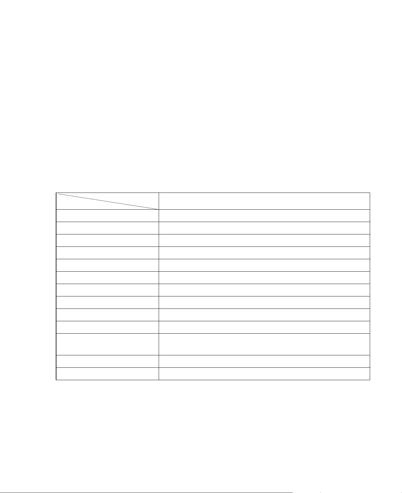
1.2 SPECIFICATIONS
MODELS
ITEMS
COOLING CAPACITY (BTU/h) 5,100
POWER SUPPLY (Phase, V, Hz)1ø, 115V, 60HZ
INPUT (W) 520
OPERATING CURRENT (AMP.) 4.4
REFRIGERANT CONTROL CAPILLARY TUBE
REFRIGERANT CHARGE (R-22) 330g (11.6 oz)
INSIDE FAN TURBO FAN
OUTSIDE FAN PROPELLER FAN WITH SLINGER RING
AIR DISCHARGE 2-WAY (RIGHT AND LEFT)
CHASSIS TOP-DOWN
PROTECTOR
TEMPERATURE CONTROL THERMISTOR
FAN MOTOR 6 POLES, 21W
• OVERLOAD PROTECTOR FOR COMPRESSOR
• INTERNAL PROTECTOR FOR FAN MOTOR
Page 4
—4—
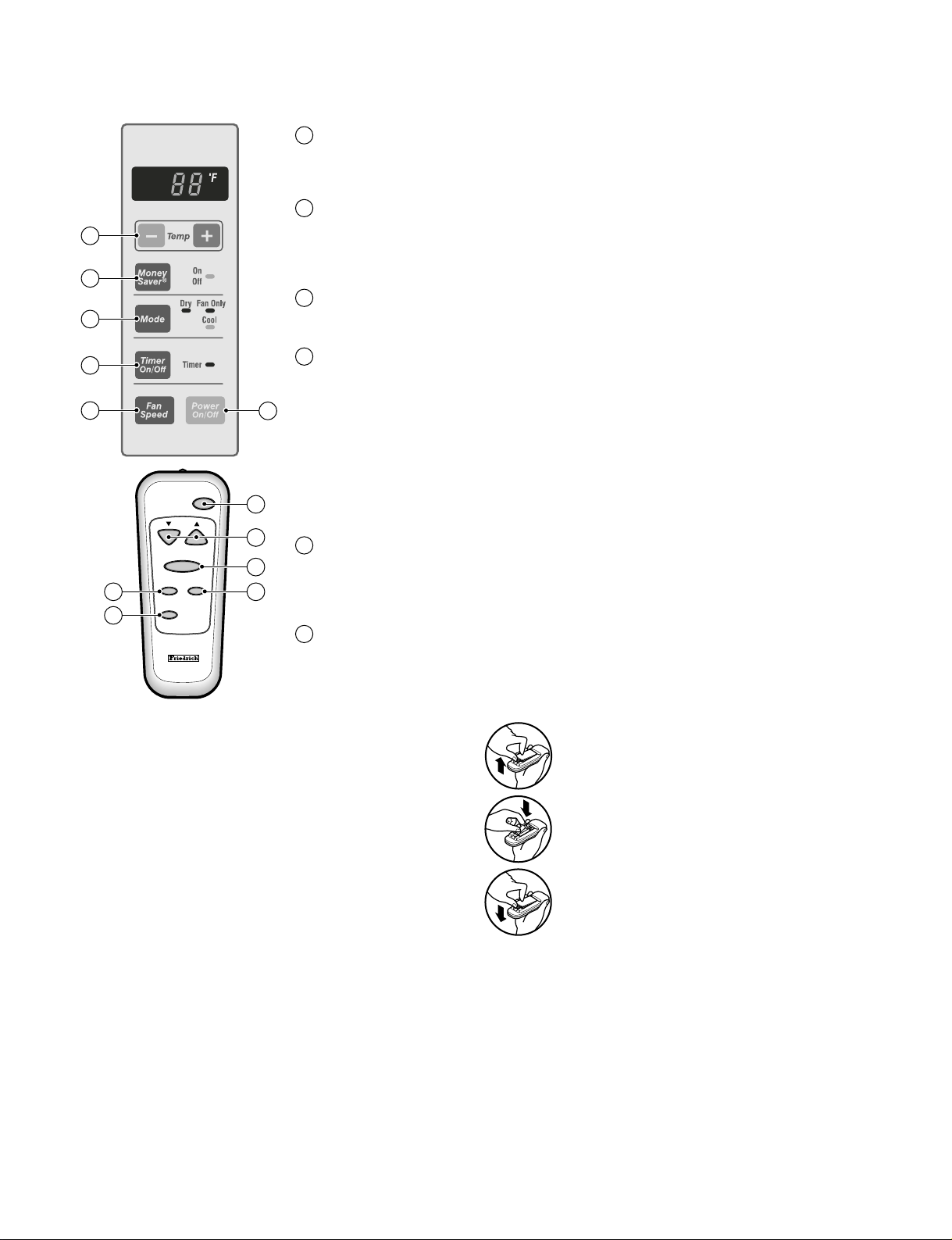
1.3 LOCATIONS OF CONTROLS
1
2
3
4
6
5
MONEY SAVER
2
The fan stops when the compressor stops cooling.
• Approximately every 3 minutes the fan will turn on and sample the room air to determine if
more cooling is needed.
TEMPERATURE SETTING
1
• These buttons control the temperature of the room.
The temperature can be set within a range of 60°F to 86°F, in increments of 1°F.
ON/OFF TIMER
4
ON–When the air conditioner is off, it can be set to automatically
come on in 1 to 12 hours from its previous setting. Each touch will increase the timer by 1
hour.
OFF–When the air conditioner is on, it can be set to automatically
turn off in 1 to 12 hours. Each touch will increase the timer by 1 hour. After the timer has been
on for 30 minutes, the temperature will automatically rise 2°F, and after another 30 minutes, it
will automatically rise 2°F again. The temperature will then stay the same until the timer goes
OFF.
To cancel the timer, press the TIMER pad until the display time disappears.
POWER
5
• To turn the unit ON, push the button. To turn the unit OFF, push the button again.
• This button takes priority over any other buttons.
• When you first turn it on, the unit is on the High cool mode and the temp. at 72°F
FAN SPEED
6
• Everytime you push this button it will rotate between the following fan speeds:
High (F3) → Low(F1) → Medium (F2) → High (F3)
Power
Temp
Fan Speed
Timer Mode
Money
Saver
5
1
6
34
2
OPERATION MODE SELECTOR
3
• Everytime you push this button, it will rotate between the COOL, FAN and DRY modes.
Page 5
—5—
2. DISASSEMBLY INSTRUCTIONS
2.1 MECHANICAL PARTS
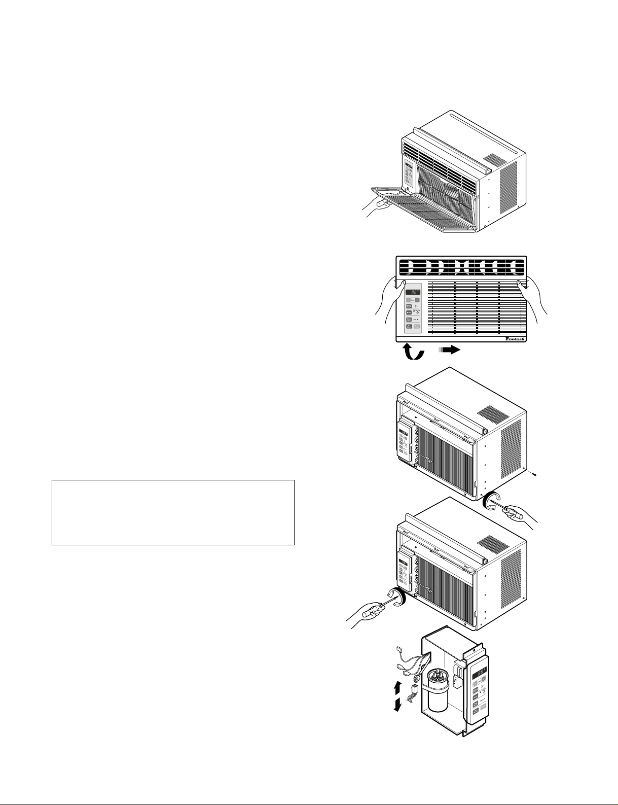
2.1.1 FRONT GRILLE
1. Pull the inlet grille forward.
2. Remove the screw securing the Front Grille. (Fig. 3)
3. Push the grille up from the bottom and pull the top of
the grille away from the case to lift the top tabs out of
their slots. (Fig. 4)
4. Carefully position the grille, bottom first, and snap back
into place.
5. Reposition the screw that secures the front grille
2.1.2 CABINET
1. Disconnect the unit from the power source.
2. Remove the front grille. (Refer to section 2.1.1)
3. Remove 9 screws that secure the cabinet to the
base pan and condenser. (See Figure 3)
4. Lift the cabinet from the unit.
5. Re-install by referring to the procedures above.
2.1.3 CONTROL 2.1.3 CONTROL PANEL
2. Remove the front grille. (Refer to Section 2.1.1)
3. Remove the cabinet. (Refer to Section 2.1.2)
4. Remove 1 screws that secure the control board to
base pan and air guide. (See Figure 4)
5. Pull the control 5. Pull the control panel toward yourself.
the fan motor and compressor. (See Figure 5)
7. Re-install components by referring to procedures
above. (Refer to wiring diagram on page 23 in this
manual or inside control board.)
Figure 1
Figure 2
Figure 3
Figure 4
Figure 5
NOTE : Controls, wires, and capacitor are now
accessible for servicing. Discharge the
capacitor before servicing. See step
2.3.3 on page 8 for procedures.
Page 6
—6—
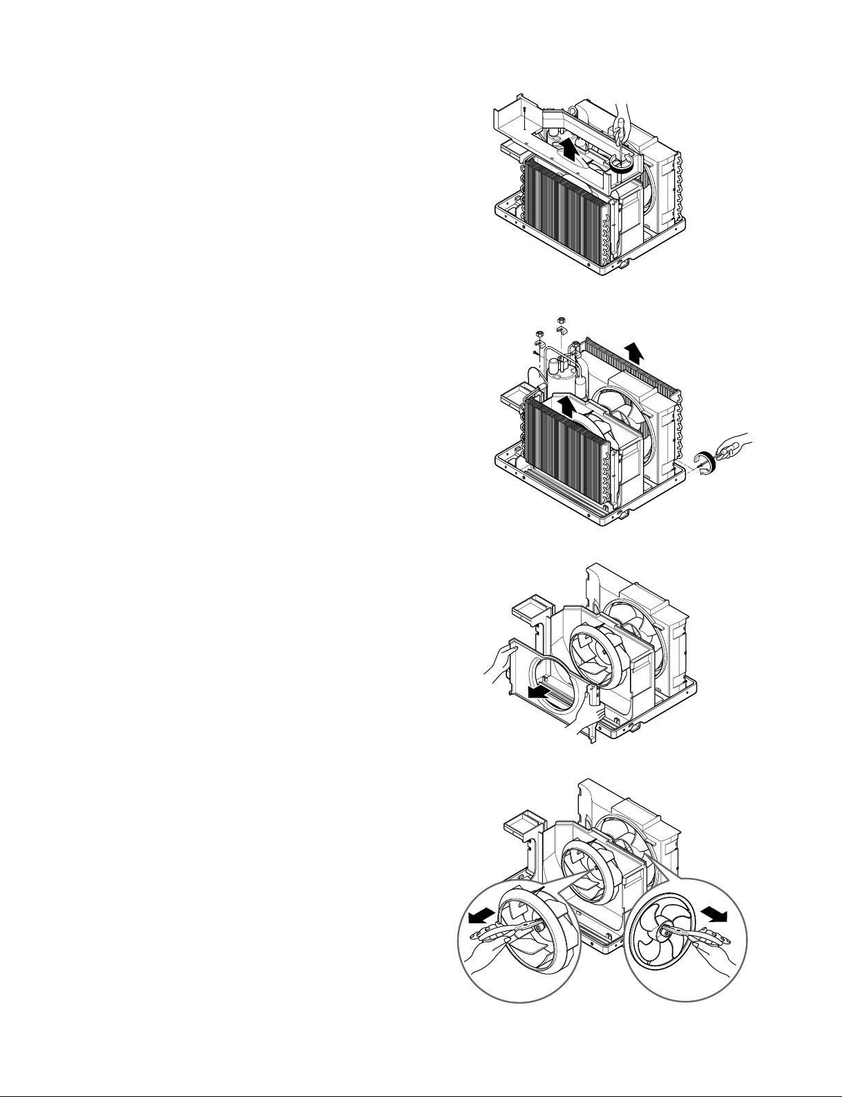
2.2 AIR HANDLING PARTS
2.2.1 AIR GUIDE UPPER
1. Disconnect the unit from the power source.
2. Remove the front grille. (Refer to Section 2.1.1)
3. Remove the cabinet. (Refer to Section 2.1.2)
4. Remove the control panel.
(Refer to Section 2.1.3)
5. Remove 2 screws that secure the upper air guide
to air guide lower. (See Figure 6)
6. Lift upper air guide upward.
7. Re-install by referring to the procedures above.
2.2.2 ORIFICE, TURBO FAN AND FAN
1. Disconnect the unit from the power source.
2. Remove the front grille. (Refer to Section 2.1.1)
3. Remove the cabinet. (Refer to Section 2.1.2)
4. Remove the control board.
(Refer to Section 2.1.3)
5. Remove the air guide upper.
(Refer to Section 2.2.1)
6. Remove 2 screws that secure the base pan to
condenser. (See Figure 7)
7. Remove screw that secures the shroud to
channel of condenser.
8. Press the snap area of shroud with your thumbs.
This allows you to remove it from the condenser.
9. Lift the compressor upward with the evaporator
and condenser. (See Figure 7)
10. Remove the orfice by pushing the snap area of
the air guide blower. (See Figure 8)
11. Remove the clamp springs which are clamped to
the shaft of fan and turbo fan by hand plier. (See
Figure 9)
12. Pull the fan and turbo fan outward.
13. Remove the shroud.
14. Re-install by referring to the procedures above.
Figure 6
Figure 7
Figure 8
Figure 9
Page 7
—7—
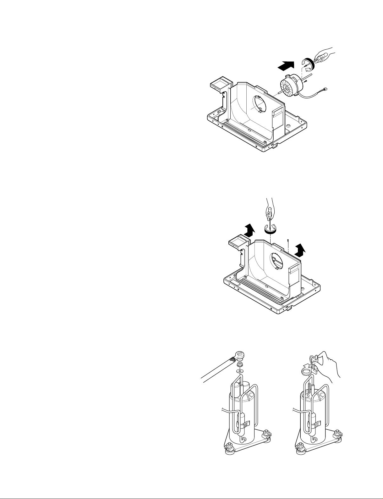
2.2.3 MOTOR
1. Disconnect the unit from the power source.
2. Remove the front grille. (Refer to Section 2.1.1)
3. Remove the cabinet. (Refer to Section 2.1.2)
4. Remove the control panel.
(Refer to Section 2.1.3)
5. Remove the upper air guide.
(Refer to Section 2.2.1)
6.
Remove the compressor, turbo fan, fan and
shroud. (Refer to
Section
2.2.2)
7.
Remove 2 screws that secure the motor to the
motor mount . (See Figure 10)
8. Remove the motor.
9.
Re-install by referring to the procedures above.
2.2.4 AIR GUIDE
1. Disconnect the unit from the power source.
2. Remove the front grille. (Refer to Section 2.1.1)
3. Remove the cabinet. (Refer to Section 2.1.2)
4. Remove the control panel.
(Refer to Section 2.1.3)
5. Remove the upper air guide .
(Refer to Section 2.2.1)
6.
Remove the compressor, turbo fan, fan and
shroud. (Refer to
Section
2.2.2)
7.
Remove the motor. (Refer to
Section
2.2.3)
8. Remove 2 screws that secure the air guide to the
base pan. (See Figure 11)
9. Push the air guide backward and lift it upward.
(See Figure 11)
10. Re-install by referring to the procedures above.
2.3 ELECTRICAL PARTS
2.3.1 OVERLOAD PROTECTOR
1. Remove the front grille and cabinet.
(Refer to Section 2.1)
2. Remove the nut which fastens the terminal cover.
3. Remove the terminal cover.
4. Remove all the leads from the overload protector.
5. Remove the overload protector.
6. Re-install the components by referring to the
removal procedure above.
(See Figure 12 and 13)
Figure 10
Figure 12
Figure 13
Figure 11
Page 8
—8—
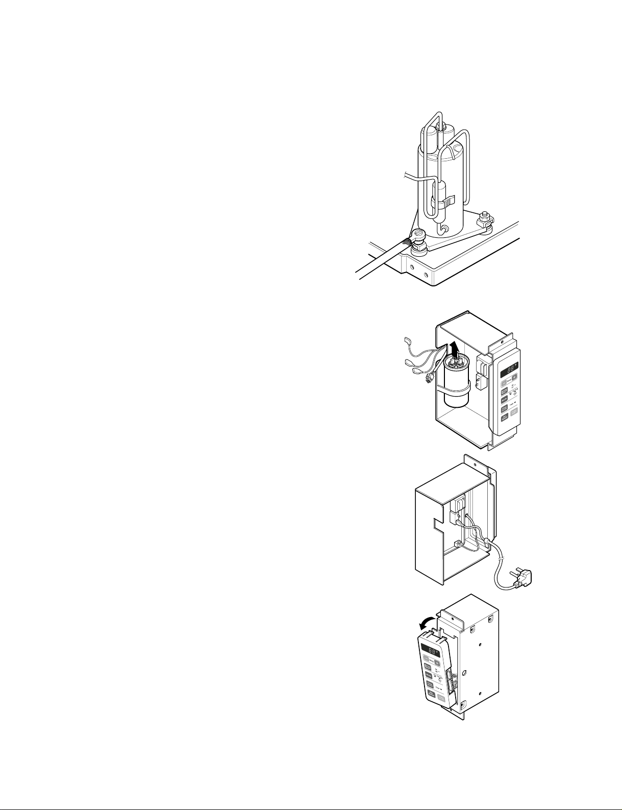
2.3.2 COMPRESSOR
1. Remove the front grille and cabinet.
(Refer to Section 2.1)
2. Discharge the refrigerant by using a refrigerant
recovery system.
3. Remove the overload protector.
(Refer to Section 2.3.1)
4. After discharging the unit completely, unbrace the
suction and discharge pipes at the compressor
connections.
5. Remove 3 nuts which fasten the compressor.
6. Remove the compressor.
7. Re-install by referring to the removal procedure
above. (See Figure 14)
2.3.3 CAPACITOR
1. Remove the cabinet. (Refer to Section 2.1.2)
2. Remove the control panel.
(Refer to Section 2.1.3)
3. Discharge the capacitor by placing a 20 KΩ
resistor across the capacitor terminals.
4. Remove the screw which fastens the capacitor
clamp.
5. Remove all the leads of capacitor terminals.
6. Re-install the components by referring to the
removal procedure above. (See Figure 15)
2.3.4 THERMISTOR
1. Remove the cabinet. (Refer to Section 2.1.2)
2. Remove the control panel.
(Refer to Section 2.1.3)
3. Disconnect the thermistor terminals from main
P.W.B assembly.
4. Remove the thermistor.
5. Re-install the components by referring to the
removal procedure above. (See Figure 16)
2.3.5 CONTROL BOARD
1. Remove the cabinet. (Refer to Section 2.1.2)
2. Remove the control panel.
(Refer to Section 2.1.3)
3. Pull the control board forward and pull out it.
4. Remove 2 lead wire terminals.
5. Re-install the components by referring to the
removal procedure above. (See Figure 17)
Figure 14
Figure 15
Figure 16
Figure 17
Page 9

—9—
2.3.6 POWER CORD
1. Disconnect the unit from source of power.
2. Remove the front grille. (Refer to Section 2.1.1)
3. Remove the cabinet. (Refer to Section 2.1.2)
4. Remove a screw that secures control panel to
base pan. (Refer to Section 2.1.3)
5. Pulls the control board toward you.
6. Disconnect the 2 receptacles and remove the
grounding screw.
7. Remove a screw securing the clip with cord to the
control panel.
8. Pull the power cord.
9. Re-install by referring to procedures above.
2.4 REFRIGERANT CYCLE
2.4.1 CONDENSER
1. Remove the cabinet. (Refer to Section 2.1.2)
2. Discharge the refrigerant by using a refrigerant
recovery system.
3. Remove the air guide. (Refer to Section 2.2.1)
4. Remove 2 screws which fasten the condenser.
5. After discharging the refrigerant completely,
unbraze the interconnecting tube at the
condenser connections.
6. Remove the condenser.
7. Re-install by referring to the procedures above.
Figure 18
Figure19
Page 10

2.4.2 EVAPORATOR
1. Remove the cabinet.
2. Discharge the refrigerant by using a refrigerant
recovery system.
3. Remove the upper air guide . (Refer to Section
2.2.1)
4. After discharging the refrigerant completely,
unbraze the interconnecting tube at the condenser
connections.
5. Remove the evaporator.
6. Re-install by referring to the procedures above.
2.4.3 CAPILLARY TUBE
1. Remove the cabinet.
2. Discharge the refrigerant by using a refrigerant
recovery system.
3. Remove the upper air guide. (Refer to Section
2.2.1)
4. After discharging the refrigerant completely,
unbraze the interconnecting tube of the capillary
tube.
5. Remove the capillary tube.
6. Re-install by referring to the procedures above.
NOTES
Replacement of the refrigeration cycle.
1. When replacing the refrigerating cycle, be sure to
discharge the refrigerant by using a refrigerant
recovery system.
2. After discharging the unit completely, remove the
desired components, and unbraze the pinch-off
tubes.
3. Solder service valves into the pinch-off tube ports,
leaving the valves open.
4. Solder the pinch-off tubes with service valves.
5. After completing the above procedures, the valve
must be removed .
6. Evacuate as follows:
6-1. Connect the vacuum pump, as illustrated in
figure 21A.
6-2. Start the vacuum pump. Slowly open manifold
valves A and B with two full turns counterclockwise and leave the valves closed.
The vacuum pump is now pulling through
valves A and B up to valve C by means of
manifold and the entire system.
CAUTION : If high vacuum equipment is used,
just crack valves A and B for a few minutes, then
open slowly with the two full turns counter-clock-
wise. This will keep oil from foaming and being
drawn into the vacuum pump.
6-3. Operate the vacuum pump for 20 to 30 min-
utes, until 600 micron vacuum is obtained.
Close valves A and B and observe vacuum
gauge for a few minutes.
A rise in pressure would indicate a possible
leak or moisture remaining in the system.
With valves A and B closed, stop the vacuum
pump.
6-4. Remove the hose from the vacuum pump and
place it on the charging cylinder. See figure
23B. Open valve C.
Discharge the line at the manifold connection.
6-5. The system is now ready for final charging.
7. Recharge as follows:
7-1. Rotary compressor systems are charged from
the high-side. If the total charge cannot be put
in the high-side, the balance will be put in the
suction line through the access valve which is
installed as the system is opened.
7-2. Connect the charging cylinder as shown in fig-
ure 21B. With valve C open, discharge the
hose at the manifold connection.
7-3. Open valve A and allow the proper charge to
enter the system. Valve B is still closed.
7-4. If more charge is required, the high-side will
not take it. Close valve A.
7-5. With the unit running, open valve B and add
the balance of the charge.
a. Do not add the liquid refrigerant to the low-
side.
b. Watch the low-side gauge, allow pressure to
rise to 30 lbs.
c. Turn off valve B and allow the pressure to
drop.
d. Repeat steps B and C until the balance of
the charge is in the system.
7-6. When the unit is operating correctly, use the
pinch-off tool with the unit still running and the
clamp on the pinch-off tube. Using a tube cutter, cut the pinch-off tube about 2 inches from
the pinch-off tool. Use sil-fos solder and solder
the pinch-off tube closed. Turn off the unit,
allow setting for a while and then test the leakage of the pinch-off connection.
—10—
Page 11

—11—
Equipment needed: Vacuum pump, charging cylinder, manifold gauge, brazing equipment, pinch-off tool capable
of making a vapor proof seal, leak detector, tubing cutter, hand tools to remove components and service valve.
B
A
B
A
B
A
COMPOUND GAUGE
SEE INSETS
BELOW
CAPILLARY TUBE
EVAPORATOR
(LOW PRESSURE SIDE)
COMPRESSOR
CONDENSER
(HIGH PRESSURE SIDE)
EXTERNAL VACUUM PUMP
LO HI
CHARGING CYLINDER
MANIFOLD
GAUGE
C
Figure 21A-Pulling Vacuum Figure 21B-Charging
Page 12

—12—
2.4.4 ELECTRICAL DATA
USE OF EXTENSION CORDS
Because of potential safety hazards, we strongly discourage the use of an extension cord. However, if you wish to use an extension
cord, use a CSA certified/UL-listed 3-wire (grounding) extension cord, rated 15A, 125V.
Do not under any
circumstances cut
or remove the
grounding prong
from the plug.
Line Cord Plug Use Wall Receptacle Power Supply
Power supply cord with
3-prong grounding plug
Standard 125V, 3-wire grounding
receptacle rated 15A, 125V AC
Use 15 AMP, time
delay fuse, or circuit
breaker.
3. TROUBLESHOOTING GUIDE
3.1 OUTSIDE DIMENSIONS (unit: mm [in])
370 (14 9/16")
312 (12 1/4")
370 (14 9/16")
312 (12 1/4")
29 (1
5
/32")
120 (4 3/4")
27.5 (1
3
/32")
346 (13
5
/8")
472 (18 9/16")
42 (1 21/32")
42 (1
21
/32")
155(6
3/32
")
12
(0.4
1/16
")
472 (18 9/16")
22.5(0.8
3/32
")
Page 13

—13—
3.2 PIPING SYSTEM
Following is a brief description of the important components and their function in what is called the refrigeration
system. Reference should be made to Figure 32 to follow the refrigerating cycle and the flow of the refrigerant in
the cooling cycle.
COOLED
AIR
HOT
DISCHARGED
AIR
MOTOR
COMPRESSOR
ROOM AIR HEAT LOAD
CAPILLARY TUBE
(LIQUID REFRIGERANT)
LIQUID OUTLET
VAPOR INLET
COMPLETE LIQUID
BOIL OFF POINT
SUCTION LINE
COOL LOW PRESSURE VAPOR
LIQUID
PRESSURE
DROP
DISCHARGE
LINE
NOT HIGH PRESSURE
VAPOR
OUTSIDE COOLING
AIR FOR REFRIGERANT
PASS THROUGH
EVAPORATOR COILS CONDENSER COILS
ROOM AIR CONDITIONER
CYCLE OF REFRIGERATION
HIGH PRESSURE VAPOR
LIQUID REFRIGERANT
LOW PRESSURE VAPOR
OIL
Figure 32
CONDENSER COILS
FAN
CAPILLARY
MOTOR
TUBE
TURBO FAN
EVAPORATOR
COILS
Page 14

—14—
3.3 TROUBLESHOOTING GUIDE
In general, possible trouble is classified in two kinds.
The one is called Starting Failure which is caused by an electrical defect. The other is Ineffective Air Con-
ditioning caused by a defect in the refrigeration circuit and improper application.
Unit is running but cooling is ineffective.
Ineffective Cooling
Satisfactory operation
with temperature
difference of inlet & outlet
air; 18~26°F.
Replacement of unit if
the unit is beyond repair.
Check outdoor coil
(heat exchanger) and
fan operation.
Check heat load
increase.
Check cold air
circulation for smooth
flow.
Check for gas leakage.
Clean condenser.
Not on dedicated circuit.
Check inside gas
pressure.
Adjust refrigerant
charge.
Malfunction of
compressor.
Replacement of
compressor.
Check for restriction in refri geration circuit.
Remove restriction in
refrigeration circuit.
Dirty indoor coil
(heat exchanger)
Repair gas leak.
Malfunction of fan.
Clogging air filter.
Obstruction at air outlet.
Remove obstruction.
Page 15

—15—
Fails to Start
Improper thermostat
setting
Loose terminal
connection
Improper wiring
Check voltage power source.
Drop of power voltage.
Capacitor check.
Replacement.
Check control switch
setting.
Compressor fails to
start.
Defect of compressor or
capacitor.
Replacement of compressor
(Motor damaged).
Irregular motor insulation (Ω)
Irregular motor resistance (Ω)
Check of circuit breaker
and fuse.
Gas leakage of feeler
bulb of thermostat.
Check control switch.
Fan fails to start.
Improper wiring.
Defect of fan motor or
capacitor.
Replacement of fan motor.
Regular but fails to start.
Replacement of compressor.
Irregular motor
resistance (Ω)
Irregular motor
insulation (Ω)
Page 16

COMPLAINT CAUSE REMEDY
Fan motor will not run. No power Check voltage at outlet. Correct if none.
Power supply cord Check voltage to electronic control board. If none,
check power supply cord. Replace cord if circuit is
open.
Wire disconnected or Connect wire. Refer to wiring diagram for
connection loose terminal identification. Repair or replace loose
terminal.
Capacitor (Discharge Test capacitor.
capacitor before testing.) Replace if not within ±10% of manufacturer's
rating. Replace if shorted, open, or damaged.
Will not rotate Fan blade hitting shroud or blower wheel hitting
scroll. Re-align assembly.
Units using slinger ring condenser fans must
have 1/4" inch clearance to the base.
If necessary, shim up the bottom of the fan motor
with mounting screw(s).
Check fan motor bearings; if motor shaft will not
rotate, replace the motor.
Fan motor runs. Revolves on overload Check voltage. See limits on this page.
If not within limits, call an electrician.
Test capacitor.
Check bearings. Does the fan blade rotate
freely?
If not, replace fan motor.
Pay attention to any change from high speed to
low speed. If the speed does not change,
replace the motor.
—16—
ROOM AIR CONDITIONER VOLTAGE LIMITS
NAME PLATE RATING MINIMUM MAXIMUM
115V ± 10% 103.5V 126.5V
Page 17

—17—
COMPLAINT CAUSE REMEDY
Fan motor noise. Fan blade If cracked, out of balance, or partially missing,
replace it.
Blower wheel If cracked, out of balance, or partially missing,
replace it.
Loose set screw Tighten it.
Worn bearings If knocking sounds continue when running
replace the motor. If the motor hums or
noise appears to be internal while running,
replace motor.
Compressor will not run, Voltage Check voltage. See the limits on the preceding
fan motor runs. page. If not within limits, call an electrician.
Wiring Check the wire connections; if loose, repair or
replace the terminal. If the wires are disconnected, refer to wiring diagram for identification,
and replace the wires. Check the wire connections;
If not according to the wiring diagram, correct
the connections.
Thermistor Check the TEMP control. If not at the lowest
number, set TEMP control to this setting.
Check the continuity of the thermistor. Replace
the control board if the circuit is open.
Capacitor (discharge Check the capacitor.
capacitor before Replace if not within ±10% of manufacturer’s
servicing.) rating, replace if shorted, open, or damaged.
Compressor Check the compressor for open circuit or
ground. If open or grounded, replace the
compressor.
Overload
Compressor cycles on Voltage Check the voltage. See the limits on the
overload. preceding page. If voltage is not within these limits,
Overload Check overload, if externally mounted.
Check the compressor overload if externally mounted.
Replace if open. (If the compressor temperature is
high, remove the overload, cool, and retest.)
call an electrician.
Replace if open. (If the compressor temperature
is high, remove the overload, cool, and retest.)
Page 18

—18—
COMPLAINT CAUSE REMEDY
Compressor cycles on Fan motor If not running, determine the cause. Replace if
overload. required.
Condenser air flow Remove the cabinet, inspect the interior surface
restriction of the condenser. If restricted, clean carefully
with a vacuum cleaner (do not damage fins) or
brush. Clean the interior base before
re-assembling.
Condenser fins If the condenser fins are closed over a large
(damaged) area on the coil surface, head pressures will
increase, causing the compressor to cycle.
Straighten the fins or replace the coil.
Capacitor Test the capacitor.
Wiring Check the terminals. If loose, repair or replace.
Refrigeration system Check the system for a restriction.
Insufficient cooling Air filter If restricted, clean or replace.
Unit undersized Determine if the unit is properly sized for the
area to be cooled.
Excessive noise Blower or fan Check the set screw, or clamp. If loose or miss-
ing, correct. If the blower or fan is hitting scroll
or barrier, rearrange the air handling parts.
Copper tubing Remove the cabinet and carefully rearrange the
tubing not to contact the cabinet,
compressor, shroud, and barrier.
Page 19

—19—
4. CIRCUIT DIAGRAM
WH(BL)
POWER INPUT
BK(BR)
(Ribbed) (Plain)
GN/YL
(GN)
GN/YL(GN)
THERMISTOR
BK BK
BLRDBL
RD
CN-TH1
YL YL
OR(BR) OR(BR)
OR
SYNC
MOTOR
RY-LO
RY-HI
CN-WORK
CN-SYNC CN-DISP
DISPLAY P.W.B ASM
RY-SYNC
250V/T2A
(115V/T2A)
TRANS
FORMER
ZNR
43
RY-COMP
MAIN P.W.B ASM
BK
BK
WH
BK
RD
BL BL
OLP
RD
MOTOR
CAPACITOR
F
R
S
COMP.
C
C
H
3854A20022K
WIRING DIAGRAM
RY-MID
FUSE
LOC
ATION
NO.
DESCRIPTION
1 POWER CORD ASSY
PART NO.
CP05C10
67300020
2 FAN MOTOR 67303026
3 COMPRESSOR 67301616
67300718
4 CAPACITOR
OVERLOAD PROTECTOR 67301405
5
Q'TY
PER SET
1
1
1
1
1
Page 20

—20—
5. EXPLODED VIEW
352390
130410
359012
W48602
354210
349480
352390-1
149980
559011
346811
554030
W48602
130910
550140
554160
567502
352115
552102
352111
352113
35211A
135313
135303
152302
135312
132111-2
132111-1
147582-1
147581
159900-1
269310
238310
W0CZZ
249950
268714
263230
137215
268712
267110
749740
Page 21

6. SERVICE PARTS LIST
• CP05C10
—21—
NOTE) *Please ensure GCSC since these parts may be changed depending upon the buyer's request.
(GCSC WEBSITE http://biz.LGservice.com)
R: Service Parts
N: Non Service Parts
LocNo FRIEDRICH DESCRIPTION
130410 67302921 Base Assy Single
130910 67303709 Cabinet Assy Single
135312 67306003 Grille Assy Front
135313 67304200 Grille Assy Inlet
14758
1 67304600 Link
147582-
149980 67303115 Shroud
152302 67304300 Filter (Mech)
238310 67500115 Escutcheon
269310 67300020 Power Cord Assy
349480 67307700 Remote Controller
352111 6730761
352115 67307612 PWB(PCB) Assy Main
35238
352390 67303026 Motor Assy Single
354210 67303410 Orifice
35211A 67302222 Tube Assy Suction
352113 67302306 Tube Assy Discharge
352115 6730202
352390-1 67302727 Air Guide Assy Upper
35239
550140 67301900 Isolator Comp
352111 67302120 Tube Assy Capillary
554160 67301616 Compressor
559011 67302613 Fan Assy Axial
359012 67302612 Fan Turbo
567502 67301405 O.L.P.
W0CZZ 67300718 Capacitor
1 67304501 Louver Vertical 2 ea.
0 67307806 Thermistor
0 67302734 Air Guide Assy Lower
CP05C10
1 PWB(PCB) Assy Display
1 Tube Assy Evaporator In
W48602 67302500 Clamp Spring
13211
1-1 67306310 Installation Kit w/Curtains L
13211
1-2 67306311 Installation Kit w/Curtains R
749740 67304005 Upper Guide Cabinet
Page 22

—22—
MEMO
Page 23

—23—
MEMO
Page 24

Post Office Box 1540 • 4200 N. Pan Am Expressway • San Antonio, Texas 78295-1540
• (210) 357-4400 • FAX (210) 357-4490
FRIEDRICH AIR CONDITIONING CO.
Visit our web site at www.friedrich.com
CP05.Svc (05/06)
Use Factory Certified Parts...
 Loading...