

Page 1
INSTALLATION &
OPERATION GUIDE
920-075-08 (10-06)
VERT-I-PAK® A-SERIES
SINGLE PACKAGE
VERTICAL AIR
CONDITIONING SYSTEM
9,000 - 18,000 BTU/h
Page 2

920-075-08
Table of Contents
I. General Specifi cations
Installation Recommendations .......................................................................................................................................... 3
Model Number Identifi cation Guide ................................................................................................................................... 4
VERT-I-PAK Chassis Specifi cations .................................................................................................................................... 4
II. Installation
1. Utility Closet Dimensions ................................................................................................................................................... 5
2. Wall Plenum & Architectural Louver Installation ................................................................................................................ 6
3. Electrical Information...................................................................................................................................................... 7-9
4. Indoor Re turn Air Grille Installation .................................................................................................................................. 10
5. Ductwork Preparation and CFM ....................................................................................................................................... 11
6. Chassis Installation .......................................................................................................................................................... 11
7. Chassis Final Connections (Electrical, Duct, Drain & Wall Thermostat) ............................................................................12
8. Final Installation Checklist ............................................................................................................................................... 12
III. Chassis Operation
9. Thermostat Control ..........................................................................................................................................................13
10. Low Ambient Protection for Compressor & Fan ................................................................................................................13
11. Heating Defrost (Heat Pump Models only) ........................................................................................................................ 13
12. Fresh Air Door ...................................................................................................................................................................13
13. Condensate Disposal System .......................................................................................................................................... 13
IV. Service & Warranty
14. Servicing / Chassis Quick Changeouts............................................................................................................................. 13
15. Warranty........................................................................................................................................................................... 14
V. Vert-I-Pak Accessories .................................................................................................................................................... 15
Please read this manual thoroughly prior to equipment installation or operati on. It is the installer’s
responsibility to properly apply and install the equipment. Installation must be in conformance
with the NFPA 70-2002 National Electric Code or current edition and Universal Mechanical Code
current edition and applicable local or national codes.
Proper installation is not diffi cult but it is essential.
2
Page 3
920-075-08
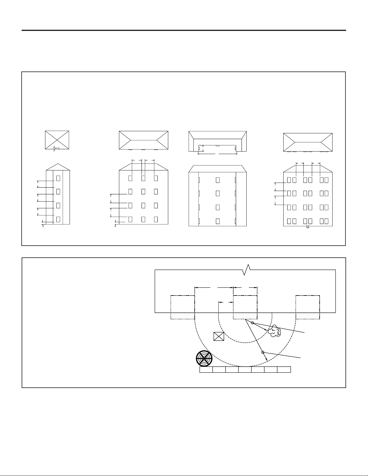
Vert-I-Pak Installation Recommendations
For proper unit performance and maximum operating life please refer to the minimum installation clearances
below.
Fig ure 1
VERT-I-PAK® units must be installed on an outside wall. Confi ned spaces and/or covered areas should be
avoided. Units should be installed no closer than 12" apart when two units are side by side. If three of more
units are to operate next to one another allo w a minimum of 60" between units or pairs of units. Also , a vertical
clearance of 60" should be maintained between units. Units installed on the bottom fl oor should be mounted
at least 6" off of the ground.
6"
SMALL RECESS OK
60"
60"
60"
6"
60" 60"
60"
60"
6"
B
A
LARGER RECESS OK. IF A> 5xB
60"
60"
60"60"
12"
Fig ure 2
Any time obstructions are present use
the following guidelines for proper
spacing from the VERT -I-PAK louver:
• For minor obstructions such as lamp
poles or small shrubbery a clearance
of 24" from the outdoor louver should
be maintained.
• For major obstructions such as a solid
fence, wall or other heat rejecting
device like a condensing unit, a minimum distance of 72" should be kept.
VPAK VPAK VPAK
POLE
OUTDOOR
CONDENSING
UNIT
BUILDING
24"60"
12"
24"
SHRUB
72"
FENCE
MAJOR OBSTRUCTION
The abov e suggestions are for ref erence only and do not repr esent all possible instal lations. Please contact the fa ctory
for information r egard ing a ffects of other i nstal latio n arrange ments .
By following th ese si mpl e recomme nda tion s yo u can be confi dent that your Friedrich Vert-I-Pak
®
will provide y ea rs
of worry-free operation.
3
Page 4
920-075-08
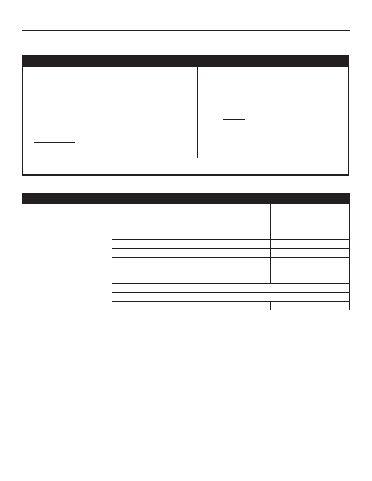
Section I. General Specifi cations
Vert-I-Pak® Model Identifi cation Guide
MODEL NUMBER V E A 09 K 34 RT H
SERIES
V=Verti cal Series
E =Cooling with elec t ric heat
H =Heat Pump
DESIGN SERIES
A = 32"/47" Cabinet
NOMINAL CAPACITY
A Series (Btu/ h)
09 = 9,00 0
12 = 12,000
VOLTAGE
K = 208/2 30V-1Ph-60Hz
18 = 18,00 0
24 = 24,000
ELECTRIC HEATER SIZE
A Series
25 = 2.5 KW
34 = 3.4 KW
50 = 5.0 KW*
75 = 7.5 KW**
Refer to electrical data chart for heater/unit compatibility.
* Not available on 9000 BTU models.
** 24000 BTU only.
OPTIONS
RT = Stan dard Re mote Op er a tion
Vert-I-Pak® Chassis Specifi cations
MODEL: V(E,H)A09 V(E,H)A12 V(E,H)A18
Voltage (V) 230 / 208 230 / 208 230 / 208
Refrigerant R-22 R-22 R-22
Chassis Width 23. 125" 23. 125" 23. 125"
Chassis Depth 23. 125" 23. 125" 23. 125"
Chassis Height ** 32.25" 32.25" 32.25"
Shipping W x D x H 26.00" x 28.50" x 35.00" 26.00" x 28.50" x 35.00" 26.00" x 28.50" x 35.00"
Supply Duct Collar *** 10" 10" 10"
Drain Connection 3/4" FPT 3/4" FPT 3/4" FPT
Min. Circuit Amps See Chassis Nameplate
CFM Indoor See Charts 2 & 3 (Page 10)
Max. Duct ESP .3 in. water .3 in. water .3 in. water
EN GI NEER ING CODE
NOTES:
** Height includes 2" duct collar & isolators under unit.
*** Factory collar accepts 10" fl ex duct.
4
Page 5
920-075-08
II. Installation
1) Utility Closet Dimensions
Recommended utility closet dimensions and a typical indoor installation are illustrated in Figure 3. Three inches minimum clearance on
three sides of the unit must be allowed for return air fl ow, installation access and servic e access. See Figures 3 and 4 for clear anc es
and ref er ence di men sions.
Fig ure 3
25" x 20" Filter
(Field Supplied)
VPRG4 Access Panel and
Return Air Filter Grille
See Figure 8, Page 10
for return air options
• Vert-I-Pak Chassis dimensions:
1
/8" wide x 23 1/8" deep x 32 1/4" high.
23
• VPAWP1-8/1-1 4 W all Plenum cut-out
dimensions 24
• VPRG4 Access Panel cutout dimensions:
27" wide by 55
• See Figure 9 (Pg 11 ) for proper chassis
installation.
5
/8" wide x 30 7/8" high.
3
/4" high.
Typical Utility Closet
Thermostat
Wiring
Power
Disconnect
Optional fi eld
installed dran pan
(refer to local codes)
Optional
Platform
Chassis Shown in Closet, on Optional Platform
Rigid Ductwork
Electrical
Connection
Exterior Wall
Flexible Ductwork
VPAWP1-8/1-14
Wall Plenum
Plenum Divider
3/4" FPT Drain
Connection
Chassis installs
3
2
/8" into Plenum
3" Clearance on all three sides
minimum for service and installation.
Fig ure 4
Top View
Outside Wall
5
Page 6

920-075-08
2) Wall Plenum and Architectural Louver Installation
A. Install the wall plenum (VPAWP1 -8/1- 14) components in accordance with the in stal la tion instructions provided with each accessory.
IMPORTANT REMINDER: FRIEDRICH WALL PLENUM IS NOT DESIGNED TO CARRY STRUCTURAL
LOADS. PROPER WALL HEADER CONSTRUCTION IS REQUIRED. THE PLENUM RE QUIRES
PROP ER FLASHING, SHIM AND CAULK FOR A WEATH ER RESISTANT INSTALLATION.
B. Ensure that the divider is adjusted properly for the depth of the wall in accordance with the accessory installation manual
Fig ure 5
Wall Ple num & Outdoor Louver In stal la tion
Proper Header
Proper Flashing
Proper Caulking
Inside Wall Plenum
(Part B)
Caulk all 8
fl ange cor ners
.
Outside Wa ll
Architectural louver VPAL2 mounted
on the outside wall plenum (Part A)
• Rough opening dimension 24 5/8" wide x 30 7/8" high.
• Ensure that the bottom of the plenum is
• For proper airfl ow, maintain a minimum distance of 12" between Vert-I-Pak units (see Figure 1, page 3).
Consult the factory for any installation or application questions.
6
3
/4" from the fl oor of the closet.
Proper Flashing
Proper Caulking
Page 7

3) Electrical Data
Electrical Data
Model
920-075-08
V(E,H)A09K25
Voltage ( V) 230/208 230/208 230/208 230/208 230/208 230/208 230/208 230/208 230/208
LRA - Comp. (A) 21 21 21 24.0 24.0 24.0 47 47 47
Cooling Current (A) 4.4/4. 9 4.4/4. 9 4.4/4.9 5.5/6.1 5.5/6.1 5.5/6.1 9.2/10.2 9.2/10.2 9.2/10.2
MIN. Ckt. Amps (A) 15 20 30 15 20 30 15 20 30
Power Connection HARD WIRED HARD WIRED HARD WIRED
V(E,H)A09K34
V(E,H)09K50
V(E,H)A12K25
V(E,H)A12K34
V(E,H,)A12K50
V(E,H)A18K25
V(E,H)A18K34
V(E,H)A18K50
Sample Name plate (see your chassis name plate)
MODEL NO 1
SERIAL NO *
FRIEDRICH AIR CONDITIONING CO.
SAN ANTONIO, TEXAS
VOLTS: 24,33,34
VOLTAGE RANGE: 255-197
REFRIG CHARGE: 7 OZS. R22
DESIGN PRESSURE: 575 PSIG HS / 150 PSIG LS
COOLING: BTU/HR 8
SEER: 10 COP: 16
HEAT PUMP BTU/HR: 14
TOTAL COOLING AMPS: 9
TOTAL ELEC. HEAT AMPS: 15
ELECTRIC HEAT WATTS: 18
FOR PERMANENTLY CONNECTED UNITS ONLY:
COMP'. PLA 11 LRA 12
MOTOR: FLA 13 HP 19
HEATER AMPS: 17
MIN. CKT AMP ~0 USE ~1 MAX. TIME DELAY FUSE
OR HACR TYPE CIRCUIT BREAKER.
GENERAL UNIT INFORMATION:
MAX OUTLET AIR TEMPERATURE: 2OO'F
MAX EXTERNAL STATIC PRESSURE ELECTRIC
HEAT'..5 IN. WATER
"O" CLEARANCE TO COMBUSTIBLE MATERIAL
USE ON SINGLE OUTLET CIRCUIT ONLY
SAMPLE
WARNING
ELECTRICAL SHOCK AND
MOVING PARTS HAZARD
CAN CAUSE INJURY OR
DEATH
PULL OUT DISCONNECT
HEAD LOCATED ON THE
FRONT OF THIS UNIT TO
DISABLE POWER BEFORE
SERVICING.
LISTED
120524
HEATING AND
COOLING EQUIPMENT
APPLICABL E PATEN TS :
US 6,065,296
NY MEA NO.: 295-00-E
USE ONE OF THE
FOLLOWING ITEMS
FROM EACH CATEGORY
TO COMPLETE THE
ASSEMBLY
WALL PLENUM:
VPA WP 1 -8
VPA WP 1 - 14
OUTDOOR GRILLE
VPAL2
INDOOR GRILLE
VPRG1
VPRG2
VPRG5
Import ant: all 20 8 /2 3 0v c has sis must be hard w ired w ith p rop er ly sized brea ker. See nameplate for specifi c chassis
electrical requirements. See page 8 - Figure 5 for unit wiring and wall thermostat wiring. See page 8 for wire size. Use
HACR type breakers to avoid nuisance trips. All fi eld wiring must be done in accordance with nec and local codes.
7
Page 8

3) Electrical Data (continued)
920-075-08
Figure 6
Electrical Requirements
Note: All fi eld wiring must comply with NEC and local codes. It
is the responsibility of the installer to insure that the electrical
codes are met.
Wire Siz e
Fuse/Circuit
Breaker
Grounding
Wire Sizi ng
Use ONLY wiring size recommended for single
out let bran ch ci rcuit.
Use ONLY type and size fuse or HACR circuit
breaker indicated on unit's rating plate (See sample
on page 6). Proper current prot ection to the u nit is
the responsibility of the own er.
Unit MUST be grounded from branch circuit to
unit, or through separate groun d w ir e pr ovi ded on
permanently connected units. Be sure that branch
circuit or general purpose outlet is ground ed.
Use recommended wir e size given in tables and
install a single branch circuit. All wiring must comply
with local and national codes. NOTE: Use copper
conduc t ors o n ly.
Electrical Rating Tables
NOTE: Use copper conductors ONLY. Wire sizes are per
NEC. Check local codes for over seas ap pli ca tions
Recommended branch circuit wire sizes*
Nameplate
maximum circuit
breaker size
15A 14
20A 12
30A 10
AWG — American Wire Gauge
* Single circuit from main box
** Based on copper wire, single in su lat ed conductor at 60°C
AWG Wire size**
CAUTION
Elec tric shock haz ard.
Tu rn O F F e l ec tric pow er be fore servic e
or in stal la tion.
All electrical connections and wir ing MUST
be in stalled by a qual i fi ed elec tri cian and
con form to the Na tion al Elec tri cal Cod e and
all local codes which have ju ris dic tion.
Failure to do so can result in prop er ty
damage, per son al injury and/or death.
8
Page 9

3) Electrical Data (continued)
Figure 7
Electrical & Thermostat Wiring Diagrams
920-075-08
208V 240V
RT4
THERMOSTAT
(FRONT)
Note: the diagram above illustrates the typical thermostat wiring and 208 volt transformer wiring.
See the unit control panel for the actual unit wiring diagram and schematic.
9
Page 10

920-075-08
4) Indoor Return Air Grille Installation
There are two Indoor Return Air Grille options as shown in Figure 8. Choose the option that best suits your needs. Use the installation
instructions provided with accessories for installation details.
Figure 8
Return Air Grille Op tions
Option 1
VPRG4
Return Air Grille with Access Panel
A fi eld-supplied (25" x 20") fi lter is
mounted inside the hinged access door.
Option 2
Field Supplied
All Vert-I -Pak chassis are shipp ed with a
14 x 20 fi lter installed. If an accessory fi lter
holder is to be used, you MUST remove the
factory shipped fi lter from the chassis. Do
NOT use two fi lters
Return Air Grille
Must have a minumum of
220 square inches of free
area.
Notes:
A. These are the Friedrich recommended return air grille / fi lter / access panel arrangements. Consult the factory on other
arrangements. Im prop er return air arrangements will cause per for mance problems.
B. Return air arrangements are shown from the front, but can also be installed from the right or left side of the unit.
10
Page 11

920-075-08
5) Ductwork Preparation
1) Duct ESP:
To determine your system's indoor external static pressure
(ESP, in inches of water) use a duct calculator (as provided
by your duct supplier). Include all fl ex duc t tran sition s and
discharge grille(s). If fl ex duct is used, be sure all the slack
is pulled out of the fl ex duct. Flex duct ESP can increase
considerably when not fully extended. DO NOT EXCEED a
total of .30 ESP, as this is the MAXIMUM design limit for the
VERT-I-PAK A-Series u n it .
2) Determining the Indoor CFM: Chart A – CFM
ESP ( ") Capacity
BTU/h 18000 12000 / 9000
.00 520 420
.10 510 410
.20 500 370
.30 490 330
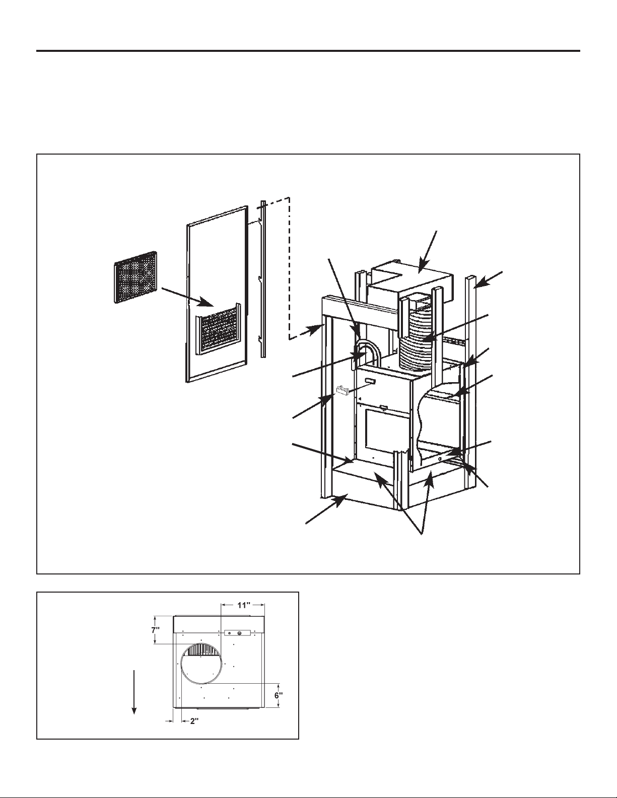
6) Chassis Installation
Install the following components as shown in Figure 5.
A. Ensure that the wall plenum is installed in accordance with
the VPAWP1 -8/1-14 Installation Manual.
B. Place the chassis into the closet with the outdoor side
facing the wall plenum opening.
C. Slide the c hassis into the wall plenum until the plenum
divider seal is established. (See Figure 9)
Figure 9
Slide-in View / Chassis Installation
3) Correct CFM (if needed):
Chart B – Correction Multipli
Correction Multipliers for:
230V 1.00
208V 0.97
Heating 1.00
Cooling 0.95
ers
The Vert-I-Pak chassis must be inserted into the wall plenum so that the
plenum divider gasket makes contact with the plastic condenser baffl e on
the unit. The chassis will fi t approximately 2
3
/8" into the wall plenum.
11
Page 12

920-075-08
7) Chassis Final Connections
With the chassis in place, you are now ready to begin chassis
connections:
A. Move the thermost at switches to "OFF" and "AUTO." This
will keep the ther mo stat from cy cling the chassis until fi nal
connections are com plete.
B. Connect the ductwork onto the 10" collar. Plas tic wireties (fi eld
sup plied) are suggested to se cure the ductwork in place. Use
2 wire ties, one for each inner and outer fl ex duct sleeve.
C. Using the t wo 3/4" plugs supplied with the unit, plug t wo of
the condensate drain holes. Connect a drain to the third
condensate exit location. Be sure to use tefl on tape or
approved pipe sealant on all drain connections and plugs.
(See Figure 10.)
D. For 208 Volt pow er only: you must move the trans form er wire
as shown in Fig ure 7, Page 9.
Electrical shock and moving parts hazard can cause injury
or death. If you have not done so, pull out the disconnect
head found on the front of chas sis before continuing installation! Disconnect external power at the breaker.
E. Review the Fi nal Inst allation Check list on Page 12 before
re plac ing the pow er quick dis con nect, reconnecting power
to the chassis, plug ging in the re mote ther mo stat har ness, or
op er at ing the chassis.
Figure 10
Drain Connection
and Location
1
8
/
7
87/8"
17 x 2
CAUTION
The unit basepan has three (3) provisions (left, right, and
rear) for connecting an external condensate drain.
A fi eld supplied condensate drain system must be
connected to one of the three (left, right, or rear) 3/4"
FPT connections on the unit basepan. Use of rear fi tting
may result in staining of the outside wall.
The remaining two connections must be plugged using
the two 3/4" pipe plugs (provided) and fi eld supplied
tefl on tape or pipe joint compound.
The addition of a secondary drain pan may be required.
Follow all applicable codes.
Failure to follow these procedures may result in serious
property damage.
A fi eld supplied secondary condensate pan may be
applied. Check with local codes.
3"
1
8
/
RT4 Digital Thermostat
8) Final Installation Checklist
Correct line voltage?
Chassis deck level?
Plenum divider baffl e installed?
Wall plenum caulked? Level? Flashing?
HACR type b re aker/fuse?
Single circuit only?
Ductwork connected?
Chassis weather seal in place?
Wall thermostat wired correctly?
Chassis inserted into plenum?
12
Page 13

920-075-08
III. Chassis Operation
9) Remote Thermostat Control
The chassis requires a simple single stage heat-cool wall thermostat.
Each chassis comes with a ter minal st rip loc ated in t he electr ic al
control box. All internal chassis wiring (low & high voltage ) is factory
ready for 230 Volt operation. For 208 Volt operation a single wire
MUST BE CHANGED ON THE TRANS FORM ER. Refer to Figure
7 on page 9.
10) Low Ambient Protection
Each chassis is equipped with Low Ambient Protection in the form of
a suction line thermostat. This thermostat will prevent compressor
operation at low suction line temperatures. Each chassis is also
equipped with a factory in stalled bellows that will drain water from
the base pan to prevent the fan slinger from freezing during winter
weather.
11) Heating Defrost (Heat Pump Models Only)
All Heat Pumps have a passive heating defrost system. Defrost
occurs as needed and automatically switches to electric heat during
defrost. When the outdoor ambient temperature drops below a 45°F
factory setting, the chassis au to mat i cal ly switch es to electric heat.
As outdoor ambient temperatures rise above 45°F, the chassis
returns to the heat pump mode. The changeover temperature is user
adjustable from approximately 32°F - 55°F. The de frost thermostat
may also be used to lock out the compressor in an emergency
heat situation.
Follow all codes when working with the condensate drain
system. A secondary drain pan may be placed beneath the
chassis to prevent condensated spillage due to improper
installation or unit malfunction.
IV. Service & Warranty
14) Servicing / Chassis Quick Changeouts
The chassis is designed for quick disconnect and change out. For
minor electrical service, the control box cover lifts straight up after
the screws & disconnect head are removed. For major electrical,
refrigeration and fan servic e the chas sis must be removed from
utility closet.
To Remove the Chassis from the Closet:
A Switch the wall ther mo stat off.
B Pull the power disconnect located in the front of the chassis.
C Turn off all power to the unit at the main breaker or
disconnect.
D Disconnect the thermostat wiring.
E Disconnect the electrical connection.
F Disconnect the ductwork.
G Dis con nect the drain connection.
H Slide the chassis out of the wall ple num.
I Lift the chassis out of the utility closet.
12) Fresh Air Door
The Fresh Air Door is an "intake" system. The fresh air door is
opened via a slide on the front of the chassis located just above
the indoor coil. Move the slide left to open and right to cl ose the
fresh air door. The system is capable of up to 60 CFM of fresh air
@ ~.3" H20 internal static pressure.
13) Condensate Disposal System
The internal drain connections are 3/4" FPT fi tting s on the r igh t, le ft
and outdoor side of the unit. See Figure 10 on page 12. The chassis
is designed with a condensate drain system that has 3 parts. The
three parts work as follows:
Part 1: The system’ s fi rst stage increases energy effi ciency
utilizing a factory installed fan that slings the cold
condensate onto the hot outdoor coil.
Part 2: When high outdoor humidity prevents the slinger from
disposing of all the condensate, the excess condensate
overfl ows into the internal drain connection.
Part 3: If Parts 1 & 2 fail for any reason, excess condensate
overfl ows from a spillway directly into the wall plenum
to the outside of the building. IF THIS OCCURS, THIS
IS YOUR WARNING THA T THE CHAS SIS OR DRAIN
NEEDS SER VICING.
15) Warranty
All service work must be done by a qualified servicer. See
Warranty on the next page, and consult your dealer or contractor
for details.
Electrical shock and moving parts hazard can cause injury
or death. Pull out the disconnect head found on the front
of the chassis before servicing.
13
Page 14

920-075-08
Friedrich Air Conditioning Company
P.O. Box 1540
San Antonio, TX 78295
210.357.4400
www.friedrich.com
VERT-I-PAK® A SERIES
SINGLE PACKAGE VERTICAL AIR CONDITIONERS
LIMITED WARRANTY
SAVE THIS CERTIFICATE.
province.
In the event that your unit needs servicing, contact your nearest authorized service center. If you do not know the nearest service center,
ask the company that installed your unit or contact us - see address and telephone number above.
replacement, you must notify an authorized FRIEDRICH Air Conditioning Co. service center, distributor, dealer, or contractor of any defect
within the applicable warranty period.
When requesting service:
Unless specified otherwise herein,
FRIEDRICH VERT-I-PAK A SERIES VERTICAL AIR CONDITIONERS AND HEAT PUMPS
LIMITED WARRANTY - FIRST YEAR (Twelve (12) months from the date of installation).
or workmanship will be repaired or replaced free of charge by our authorized service center during the normal working hours; and
LIMITED WARRANTY - SECOND THROUGH FIFTH YEAR (Sixty (60) months from the date of installation). ON THE SEALED
REFRIGERATION SYSTEM.
replaced free of charge (excluding freight charges) by our authorized service center during normal working hours. The sealed refrigeration
system consists of the compressor, metering device, evaporator, condenser, reversing valve, check valve, and the interconnecting tubing.
It gives you specific rights, you may also have other rights which may vary from state to state and province to
To obtain service and/or warranty parts
please have the model
the following applies:
Any part of the sealed refrigeration system that is defective in material or workmanship will be repaired or
and serial number from your unit readily available.
Any part found to be defective in the material
These warranties apply only while the unit remains at the original site and only to units installed inside the continental United
States, Alaska, Hawaii, Puerto Rico and Canada. The warranty applies only if the unit is installed and operated in accordance with
the printed instructions and in compliance with applicable local installation and building codes and good trade practices. For
international warranty information, contact the Friedrich Air Conditioning Company - International Division.
Any defective part to be replaced must be made available to
presented to establish the date of install, otherwise the beginning date of this certificate will be considered to be our shipment date plus sixty
days. Replacement parts can be new or remanufactured. Replacement parts and labor are only warranted for any unused portion of the
unit’s warranty.
We will not be responsible for and the user will pay for:
1. Service calls to:
A) Instruct on unit operation. B) Replace house fuses or correct house wiring. C) Clean or replace air filters. D) Remove the unit
from its installed location when not accessible for service required. E) Correct improper installations.
2. Parts or labor provided by anyone other than an authorized service center.
3. Damage caused by:
A) Accident, abuse, negligence, misuse, riot, fire, flood, or acts of God. B) Operating the unit where there is a corrosive atmosphere
containing chlorine, fluorine, or any damaging chemicals (other than in a normal residential environment). C) Unauthorized
alteration or repair of the unit, which in turn affects its stability or performance. D) Failing to provide proper maintenance and
service.
We shall not be liable for any incidental, consequential, or special damages or expenses in connection with any use or failure of
this unit. We have not made and do not make any representation or warranty of fitness for a particular use or purpose and there
is no implied condition of fitness for a particular use or purpose. We make no expressed warranties except as stated in this
certificate. No one is authorized to change this certificate or to create for us any other obligation or liability in connection with
this unit. Any implied warranties shall last for one year after the original purchase date.
limitations on how long an implied warranty or condition lasts, so the above limitations or exclusions may not apply to you. The provisions of
this warranty are in addition to and not a modification of or subtraction from the statutory warranties and other rights and remedies provided
by law.
In case of any questions regarding the provisions of this warranty, the English version will govern.
E) Using an incorrect power source. F) Faulty installation or application of the unit.
FRIEDRICH
in exchange for the replacement part. Reasonable proof must be
Some states and provinces do not allow
(10-06)
14
Page 15

920-075-08
V. Vert-I-Pak Accessories
MODEL DESCRIPTION PHOTO
WALL PLENUM Two-part sleeve that telescopes in and out
1
VPAWP1-8
from 5
exterior wall penetration.
DIMENSIONS: 30 3/8" high x 24 1/8" wide.
CUTOUT DIMENSIONS: 30 7/8" high x 24 5/8" wide.
/2" to 8" in depth. The wall plenum sits inside the
VPAWP1-14
VPAL2
VPSC2
RT4
VPRG4
Same as VPAWP1-8, but telescopes 8" to 14" as required.
ARCHITECTURAL LOUVER Extruded aluminum louver
that attaches to the outdoor section of the wall plenum.
DIMENSIONS: 31
Same as VPAL2 but can be ordered in a special color to
match the exterior wall.
DIGITAL THERMOSTAT
digital thermostat for control of Friedrich VERT-I-PAK.
ACCESS PANEL / RETURN AIR GRILLE – Serves as an
access panel to chassis and interior return air grille. A
fi eld-supplied (25" x 20") fi lter is mounted inside the hinged
access door.
DIMENSIONS: 58" high x 29" wide.
CUTOUT DIMENSIONS: 55 3/4" high x 27" wide.
1
/16" high x 25 9/16" wide.
Single stage, wall-mounted
15
Page 16

FRIEDRICH AIR CONDITIONING CO. INC.
Post Office Box 1540 · San Antonio, Texas 78295-1540
4200 N. Pan Am Expressway · San Antonio, Texas 78218-5212
(210) 357-4400 · FAX (210) 357-4480
www.friedrich.com
Printed in the U.S.A.
920-075-08 (10-06)
 Loading...