

Page 1
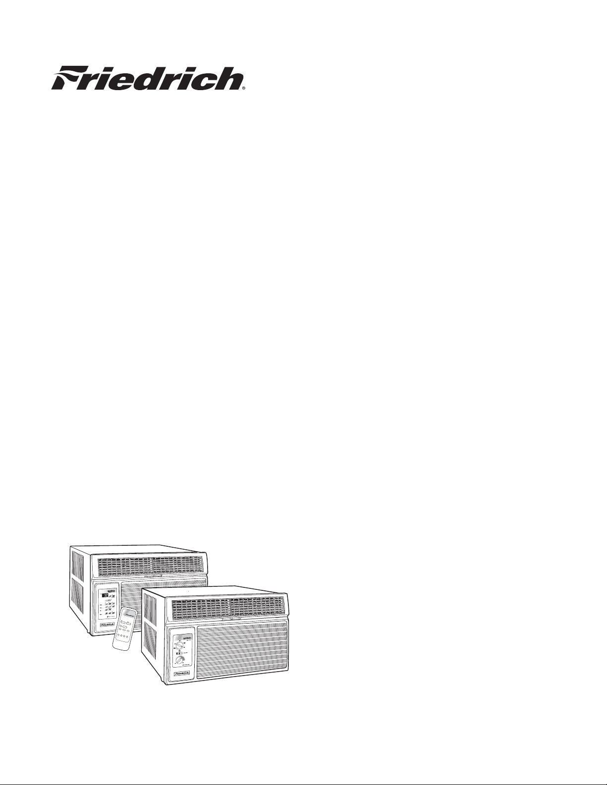
Service Manual
M
o
n
e
y
F
a
n
Timer Operation
S
e
t H
r
.
S
to
p
S
ta
r
t
Temperature
F
a
n
C
o
o
l
O
n
/O
ff
Power
C
o
o
le
r
O
n
ly
S
p
e
e
d
S
a
v
e
r
®
W
a
r
m
e
r
2007
Room Air Conditioners
RAC-Svc-07 (4-07)
Page 2
TABLE OF CONTENTS
Introduction / Typical Unit Components .......................................................................................................................................3
Warranty ....................................................................................................................................................................................... 4
Routine Maintenance ........................................................................................................... ........................................................5
Unit Identifi cation / Nomenclature ................................................................................................................................................ 6
Performance Data .........................................................................................................................................................................7
Electrical Data ..............................................................................................................................................................................8
Functional Component Defi nitions ..............................................................................................................................................9
Electronic Controls ..................................................................................................................................................................9-10
Refrigeration Sequence of Operation .........................................................................................................................................11
Sealed Refrigeration Repairs .................................................................................................................................................11 -12
Refrigerant Charging .............................................................................................................................................................13-1 5
T roubleshooting .....................................................................................................................................................................16-23
Wiring Diagrams ....................................................................................................................................................................24-35
The information contained in t his manual is intended for use by a qualifi ed ser vice technician who is familiar
with the safety procedures required i n in stal la tion a nd repair, and who is equipped with the proper tools and test
instruments.
Installation or repairs made by unqualifi ed persons can result in hazards subjecting the unqualifi ed person making
such repai rs to the risk of injury or electrical shock which can be serious or even fatal not only to them, but also
to persons being served by the equipment.
If you install or perform service on equipment, you must assume responsibilit y for any bodily injur y or property
damage which may result to you or others. Friedrich Air Conditioning Co mpany will not be responsible for any
injury or property damage arising from improper installation, service, and/or service procedures.
2
Page 3
INTRODUCTION
This service manual is designed to be used in conjunction with the installation manuals provided with each air conditioning
system component.
This servic e manual was writ ten to as sist the profes sional R AC ser v ice tec hnician to quick ly and ac curately diagnose and
repair malfunctions.
This manual will deal with subjects in a general nature. (i.e. all text will not pertain to all models).
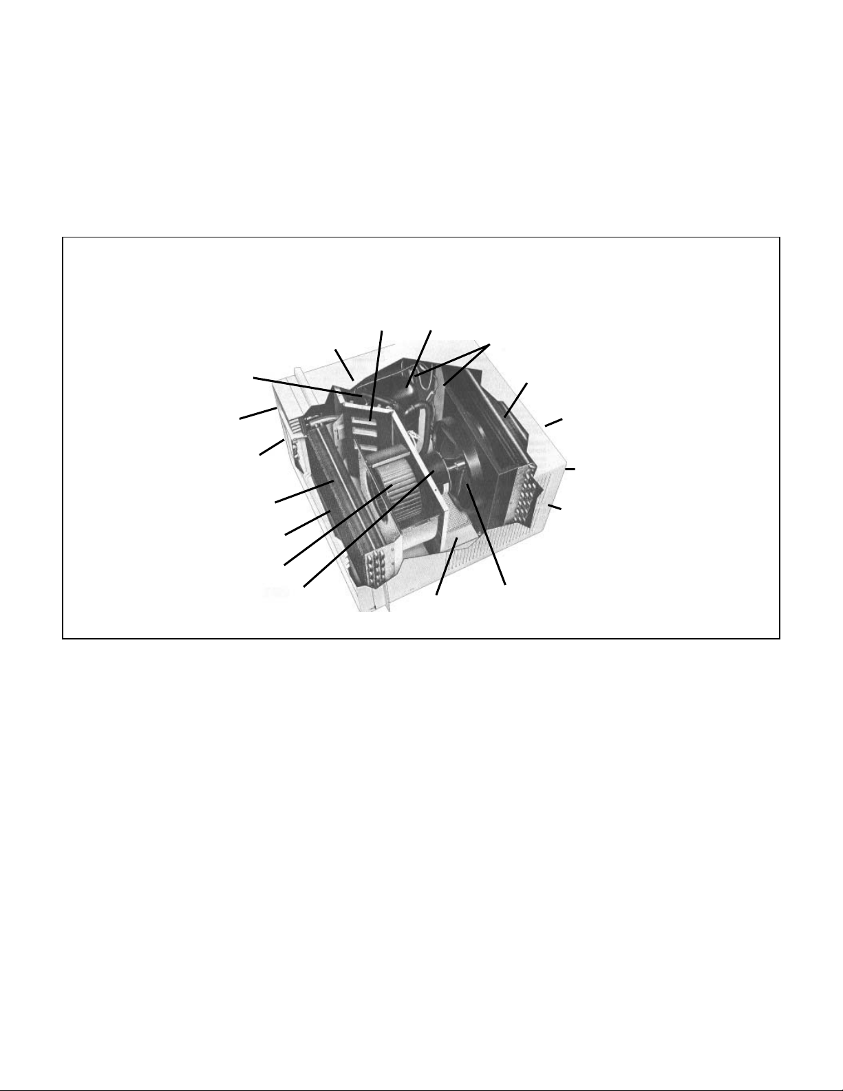
TYPICAL UNIT COMPONENTS
Capillary Tube
Reversing Valve
(some models)
Front Cover
System Switches
Evaporator Coil
Return Air Grille/Filter
Blower Wheel
Blower Motor
IMPORTANT:
diagnosis and repair (See Unit Identifi catio n).
It will be necessary for you to accurately identify the unit you are servicing, so you can be certain of a proper
Fresh Air
Compressor
Liquid Filter Driers
Condenser Coil
Discharge Air
Outdoor Grille
Sleeve
Condenser Fan Blade
Basepan
3
Page 4

Friedrich Air Conditioning Company
P.O. Box 1540
San Antonio, TX 78295
210.357.4400
www.friedrich.com
ROOM AIR CONDITIONERS
LIMITED WARRANTY
FIRST YEAR
ANY PART: If any part supplied by FRIEDRICH fails because of a defect in workmanship or material within twelve months from
date of original purchase, FRIEDRICH will repair the product at no charge, provided room air conditioner is reasonably accessible
for service. Any additional labor cost for removing inaccessible units and/or charges for mileage related to travel by a Service
Agency that exceeds 25 miles one way will be the responsibility of the owner. This remedy is expressly agreed to be the exclusive
remedy within twelve months from the date of the original purchase.
SECOND THROUGH FIFTH YEAR
SEALED REFRIGERANT SYSTEM: If the Sealed Refrigeration System (defined for this purpose as the compressor, condenser
coil, evaporator coil, reversing valve, check valve, capillary, filter drier, and all interconnecting tubing) supplied by FRIEDRICH in
your Room Air Conditioner fails because of a defect in workmanship or material within sixty months from date of purchase,
FRIEDRICH will pay a labor allowance and parts necessary to repair the Sealed Refrigeration System; PROVIDED FRIEDRICH will
not pay the cost of diagnosis of the problem, removal, freight charges, and transportation of the air conditioner to and from the
Service Agency, and the reinstallation charges associated with repair of the Sealed Refrigeration System. All such cost will be the
sole responsibility of the owner. This remedy is expressly agreed to be the exclusive remedy within sixty months from the date of the
original purchase.
APPLICABILITY AND LIMITATIONS: This warranty is applicable only to units retained within the Fifty States of the U.S.A., District
of Columbia, and Canada. This warranty is not applicable to:
1. Air filters or fuses.
2. Products on which the model and serial numbers have been removed.
3. Products which have defects or damage which results from improper installation, wiring, electrical current
OBTAINING WARRANTY PERFORMANCE: Service will be provided by the FRIEDRICH Authorized Dealer or Service
Organization in your area. They are listed in the Yellow Pages. If assistance is required in obtaining warranty performance, write
to: Room Air Conditioner Service Manager, Friedrich Air Conditioning Co., P.O. Box 1540, San Antonio, TX 78295-1540.
LIMITATIONS: THIS WARRANTY IS GIVEN IN LIEU OF ALL OTHER WARRANTIES. Anything in the warranty
notwithstanding, ANY IMPLIED WARRANTIES OF FITNESS FOR PARTICULAR PURPOSE AND/OR MERCHANTABILITY
SHALL BE LIMITED TO THE DURATION OF THIS EXPRESS WARRANTY. MANUFACTURER EXPRESSLY DISCLAIMS AND
EXCLUDES ANY LIABILITY FOR CONSEQUENTIAL OR INCIDENTAL DAMAGE FOR BREACH OF ANY EXPRESSED OR
IMPLIED WARRANTY.
NOTE: Some states do not allow limitations on how long an implied warranty lasts, or do not allow the limitation or exclusion of
consequential or incidental damages, so the foregoing exclusions and limitations may not apply to you.
OTHER: This warranty gives you specific legal rights, and you may also have other rights which vary from state to state.
PROOF OF PURCHASE: Owner must provide proof of purchase in order to receive any warranty related services.
All service calls for explaining the operation of this product will be the sole responsibility of the consumer.
All warranty service must be provided by an Authorized FRIEDRICH Service Agency, unless authorized by FRIEDRICH prior to
repairs being made.
characteristics, or maintenance; or caused by accident, misuse or abuse, fire, flood, alterations and/or misapplication
of the product and/or units installed in a corrosive atmosphere, default or delay in performance caused by war,
government restrictions or restraints, strikes, material shortages beyond the control of FRIEDRICH, or acts of God.
(10-04)
4
Page 5
ROUTINE MAINTENANCE
NOTE: Un its are to be inspected and serviced by qualifi ed service personnel only.
Routine maintenance is required annually or semi-annually, depending upon annual usage.
1. Clean the unit air intake fi lter at least every 250 to 300 fan hours of operation or when the unit’s indicator light is on if so
equipped. Clean the fi lters with a mild detergent in warm water and allow to dry thoroughly before reinstalling.
2. The indoor coil (evaporator coil), the outdoor coil ( condenser coil) and base pan should be inspected periodically (yearly
or bi-yearly) and cleaned of all debris (lint, dirt, leaves, paper , et c.). Clean the coils and base pan with a soft brush and
compressed air or vacuum. If using a pressure washer, be careful not to bend the aluminium fi n pack. Use a sweeping
up and down motion in the direction of the vertical aluminum fi n pack when pressure cleaning coils. Cover all electrical
components to protect them from water or spray. Allow the unit to dry thoroughly before reinstalling it in the sleeve.
NOTE: Do not use a caustic coil cleaning agent on coils or base pan. Use a biodegradable cleaning agent and degreaser.
Inspect the indoor blower housing, evaporator blade, condenser fan blade, and condenser shroud periodically (yearly or
bi-yearly) and clean of all debris (lint, dirt, mold, fungus, etc.) Clean the blower housing area and blower wheel with an
antibacterial / antifungal cleaner. Use a biodegradable cleaning agent and degreaser on condenser fan and condenser
shroud. Use warm or cold water when rinsing these items. Allow all items to dry thoroughly before reinstalling them.
3. Periodically (at least yearly or bi-yearly): inspect all control components, both electrical and mechanical, as well as the
power supply. Use proper testing instruments (voltmet er, ohmmeter , ammeter , wattmeter, etc. ) to perform electrical tests.
Use an air conditioning or refrigeration therm ometer to check room, outdoor and c oil operating temperatures. Use a
sling psychrometer to measure wet bulb temperatures indoors and outdoors.
4. Inspect the surrounding area (inside and outside) to ensure that the units’ clearances have not been compromised or
altered.
5. Inspect the sleeve and drain system periodically (at least yearly or bi-year ly) and clean of all obstructions and debr is.
Clean both areas with an antibacterial and antifungal cleaner. Rinse both items thoroughly with water and ensure that
the drain outlets are operating correctly. Check the sealant around the sleeve and reseal areas as needed.
6. Clean the front cover when needed. Use a mild detergent. Wash and rinse with warm water. Allow it to dry thoroughly
before reinstalling it in the chassis.
5
Page 6
UNIT IDENTIFICATION
Model Number Code
S S 08 L 1 0 A
1st Digit – Function
S = Straight Cool, Value Series
Y = Heat Pump
E = Electric Heat
K = Straight Cool
R = Straight Cool
X = Straight Cool
W = Thru-the Wall,
WallMaster Series
2nd Digit
C = Casement
Q = Q-Star
S = Small Chassis
M = Medium Chassis
L = Large Chassis
H = HazardGard
3rd and 4th Digit - Approximate
BTU/HR (Cooling)
Heating BTU/Hr capacity listed in the
Specifi cation/Performance Data Section
8th Digit – Engineering
Major change
7th Digit – Options
0 = Straight Cool &
Heat Pump Models
1 = 1 KW Heat Strip, Normal
3 = 3 KW Heat Strip, Normal
4 = 4 KW Heat Strip, Normal
5 = 5 KW Heat Strip, Normal
6th Digit – Voltage
1 = 115 Volts
3 = 230-208 Volts
5th Digit
Alphabetical Modifi er
RAC Serial Number Identifi cation Guide
Serial Number
Decade Manufactured
L=0 C=3 F=6 J=9
A=1 D=4 G=7
B=2 E=5 H=8
Year Manufactured
A=1 D=4 G=7 K=0
B=2 E=5 H=8
C=3 F=6 J=9
Month Manufactured
A=Jan D=Apr G=Jul K=Oct
B=Feb E=May H=Aug L=Nov
C=Mar F=Jun J=Sept M=Dec
6
L C G R 00001
Production Run Number
Product Line
R = RAC
P = PTAC
E = EAC
V = VPAK
H = Split
Page 7
PERFORMANCE DATA
FUSE
Amps
60 Hertz
BREAKER
Voltage
R-22
REF.
in OZ.
Charge
Locked
Rotor Amps
Heat
Amps
ELECTRICAL RATINGS
Cool
Amps
OPERATING
PRESSURES
Sub-
Cooling
Heat
Super
Temp
Suction
Temp
Discharge
DEG. F
CONDENSER
TEMPERATURE
Temp.
Discharge
EVAP. AIR TEMP. DEG. F
Suction Discharge
Drop F.
Air
DATA* Cooling
XQ05L10A-B 56 24 119 151 58 13 20 89 255 4.9 28.0 21.4 115 15
XQ06L10A-A 55 26 121 157 65 13 27 87 261 5.0 24.0 21.0 115 15
XQ08L10A-A 52 29 128 167 60 13 33 81 283 6.8 36.2 22.1 115 15
XQ10L10A-A 50 31 130 176 65 20 29 75 287 9.2 44.0 19.2 115 15
XQ12L10A-A 51 29 126 166 51 6 30 75 271 11.0 56.0 31.0 115 15
EQ08L11A-A 52 29 124 173 69 21 29 82 283 6.5 10.7 36.2 20.0 115 15
YQ07L10A-A 55 25 126 177 73 26 23 79 275 6.8 5.6 36.2 19.5 115 15
YQ07L10A-B 55 25 126 177 73 26 23 79 275 6.8 5.6 36.2 19.5 115 15
SS08L10-C 56 24 119 154 73 22 24 85 252 6.6 36.2 23.0 115 15
SS08L10-D 56 24 116 157 68 16 18 86 250-260 6.6 36.2 27.0 115 15
SS10L10-C 57 23 117 166 65 16 23 82 243 7.5 42.0 26.0 115 15
KS12L10-C 52 29 122 169 61 13 24 82 266 9.0 44.0 26.5 115 15
SS12L10-D 53 27 124 169 62 13 30 82 266 9.3 44.0 32.0 115 15
KS15L10-B 51 30 125 182 62 16 29 77 278 12.2 61.0 29.0 115 15
SS14L10-C 53 27 125 184 62 15 27 78 268 12.3 61.0 29.2 115 15
SS12L30-C 57 24 121 170 67 17 27 83 258 5.4 21.0 28.0 208 / 230 15
SS12L30-D 58 22 122 174 66 17 28 84 261 4.7 21.0 31.0 208 / 230 15
SH15L30-B 54 26 206 129 61 16 98 76 258 8.2 28.5 208 / 230 15
SS16L30-C 50 31 130 176 53 8 35 77 279 7.9 35.0 32.1 208 / 230 15
ES12L33-B 56 25 121 167 65 15 28 83 256 4.8 15.1 21.0 28.0 208 / 230 20
ES12L33-C 58 22 122 174 66 17 28 84 261 4.7 15.1 21.0 31.0 208 / 230 20
ES16L33-B 49 32 130 179 50 8 34 75 279 7.4 15.1 35.0 32.0 208 / 230 20
YS09L10-D 60 20 116 164 71 18 17 89 239 7.1 8.5 44.0 25.1 115 15
YS13L33-B 58 23 123 175 69 22 29 79 266 5.2 5.3 / 15.1 24.0 30.0 208 / 230 20
YS13L33-C 51 29 122 172 65 18 30 80 269 5.5/5.1 5.7/5.3 24.0 32.0 1 20
KM24L30-B 50 31 132 187 56 14 37 70 287 11.2 68.0 53.0 208 / 230 20
YM18L34-B 49 31 125 182 64 22 27 72 271 8.5 8.7 / 18.6 41.0 43.0 208 / 230 30
YM18L34-C 61 19 126 187 67 24 28 73 280 9.2/8.75 8.8/8.3 41.0 43.0 208/230 30
EM18L34-B 49 31 125 175 63 21 31 72 271 8.1 18.9 42.0 39.5 208 / 230 15
KM18L30-B 49 31 125 175 63 21 31 72 271 8.1 42.0 39.5 208 / 230 15
PERFORMANCE
*Rating Conditions: 80 degrees F, room air temp. & 50% relative humidity, with 95 degree F, outside air temp & 40% relative humidity.
Q-Chassis
S-Chassis
SM18L30A-B 53 28 122 175 66 13 25 82 255 7.3 37.0 44.0 208 / 230 15
SM18L30A-C 54 26 121 171 61 13 25 81 262 7.7/7.1 37.0 45.0 208/230 15
SM21L30-C 50 31 127 185 57 15 34 73 274 9.4 43.0 45.0 208 / 230 15
SM21L30-D 48 32 125 173 52 13 25 75 278 9.6/9.3 43.0 43.0 208/230 15
M-Chassis
EM24L35-B 50 31 132 187 56 14 37 70 287 11.2 25.0 68.0 53.0 208 / 230 30
SM24L30-B 50 31 132 187 56 14 37 70 287 11.2 68.0 53.0 208 / 230 20
SL28L30-C 53 28 128 172 56 13 29 73 259 13.0 68.0 50.1 208 / 230 20
SL36L30A-C 49 31 133 192 53 12 37 70 287 17.2 91.0 57.6 208 / 230 30
EL36L35A-C 49 32 133 194 53 13 38 70 302 18.0 25.0 91.0 60.0 208 / 230 30
YL24L35-C 52 29 122 175 65 23 29 72 262 10.9 11.2 / 24.6 68.0 74.0 208 / 230 30
YL24L35-D 52 28 124 175 65 22 29 74 268 11.9/11.1 11.7/11.0 68.0 73.0 208/230 30
SH15L30-B 54 26 206 129 61 16 98 76 258 8.2 28.5 208 / 230 15
SH20L30-B 46 34 125 196 52 8 28 75 271 10.1 39.0 208 / 230 20
L-Chassis
HazardGard
7
Page 8
ELECTRICAL DATA
Wire Size Use ONLY wiring size recommended for
single outlet branch circuit.
Fuse/Circuit Use ONLY type and size fuse or HACR
Breaker c ircuit breaker indicated on unit ’s rating
plate. Proper current protection to the unit
is the responsibility of the owner.
Grounding Unit MUST be grounded from branch
circuit through service cord to unit, or
through separate ground wire provided on
permanently connected units. Be sure that
branch circuit or general purpose outlet is
grounded.
Receptacle The fi eld supplied outlet must match plug on
service cord and be within reach of service
cord. Do NOT alter the service cord or plug.
Do NOT use an extension cord. Refer to
the table above for proper receptacle and
fuse type.
ELECTRIC SHOCK HAZARD.
T urn off electric power before service or installation.
All electrical connections and wiring MUST be
installed by a qualifi ed electrician and conform to the
National Electrical Co de and all local codes which
have jurisdiction.
Failure to do so can result in property damage,
personal injury and/or death.
The consumer - through the AHAM Room Air Conditioner Certifi cation Program - can be certain
that the AHAM Certifi cation Seal accurately states the unit’s cooling and heating capacity rating,
the amperes and the energy effi ciency ratio.
8
Page 9
FUNCTIONAL COMPONENT DEFINITIONS
MECHANICAL C OMPONEN TS
Bellows condensate valve Temperature-sensitive valve
that opens up to drain off condensate water when the outside
temperature falls below 40°F and closes when the outside
temperature reaches 58°F .
Ven t doo r Allows introduction of fresh air into the room
and/or exhausts stale room air outside (on select models.)
Plenum assembly Diffuser with directional louvers used
to direct the conditioned airfl ow.
Blower wheel Attaches to the indoor side of the fan motor
shaft and is used for distributing unc onditione d, room side
air though the heat exchanger and delivering conditioned
air into the room.
Slinger fan bla d e Attaches to the outdoor side of the fan
motor shaft and is used to move outside air through the
condenser coil, while slinging condens ate water out of the
base pan and onto the condenser coil, thus lowering the
temperature and pressures within the coil.
ELECTRICAL COMPONENTS
Thermostat Used to maint ain the specifi ed room side
comfo rt level
System switch Used to regulate the operation of the fan
motor, the compressor or to turn the unit off. For troubleshooting, refer to the wiring diagrams and schematics in the back
of this service manual.
Capacitor Reduc es line cur rent and steadies the voltage
supply, while greatly impro ving the torque characteristics of
the fan motor and compressor motor.
ELECTRICAL COMPONENTS cont’d
MoneySaver® switch When engaged, it sends the power
supply to the fan motor through the thermostat, which allows
for a cycle-fan operation.
Fan M otor Dual-shafted fan motor operates the indoor
blower wheel and the condenser fan blade simultaneously.
Solenoid Used to energize the reversing valve on all heat
pump units.
Heating element Electric resistance heater, available in 3.3,
4.0 or 5.2 kW on select TwinTemp
®
models.
Heat anticipator Used to provide better thermostat and
room air temperature control.
HERMETIC COMPONENTS
Compressor Motorized device used to compress refrigerant
through the sealed system.
Reversing valve A four-way switching device used on all
heat pump models to change the fl ow of refrigerant to permit
heating or cooling.
Check valve A pressure-operated device used to direct the
fl ow of refrigerant to the proper capillary tube, during either
the heating or cooling cycle.
Capillary tube A cylindrical meter device used to evenly distribute the fl ow of refrigerant to the heat exchangers (coils. )
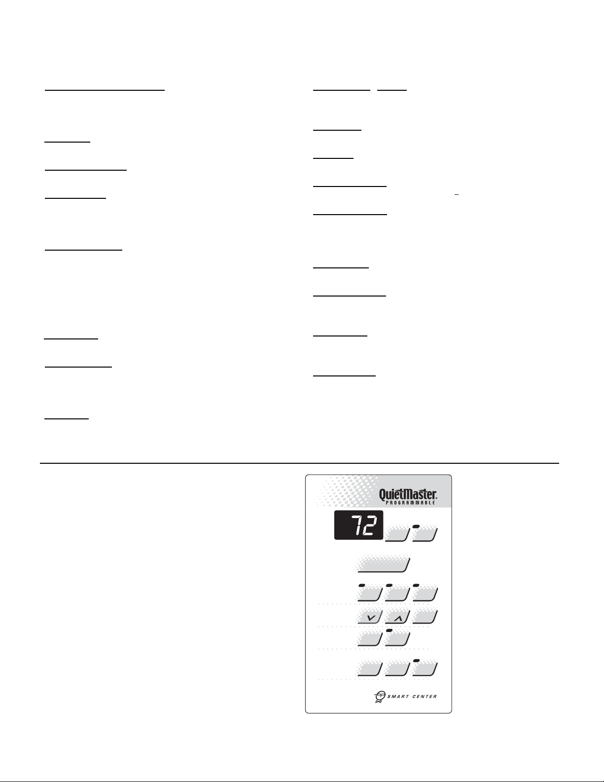
ELECTRONIC CON TROLS
TESTING THE ELECTRONIC CONTROLS
CHECK FILTER light will come on after 250 hours of use.
Touch CHECK FILTER to reset.
PM
Mode
Temp
Fan
Timer
Cool
Speed
Stop
Check
Set
Filter
Hour
Press to reset
Power
Money
Saver
1- 4
Smart
A/C
Start
Fan
®
Only
O
O
F
/
C
Fan
A/C
Timer
On/ Off
Electronic Control
9
Page 10

ELECTRONIC CONTROLS
TESTING THE ELECTRONIC CONTROL
XQ/WS BOARDS & QME BOARDS
Activating Test Mode: Activate test mode by pressing at
the same time the “MODE” button and the temperature
“DOWN” button on XQ & WS models. LEDs for Hour, Start,
and Stop will blink 1 bps while T est Mode is active.
Activate test mod e by pressing at the same time the “MONEY
SAVER” button and the “CHECK FILTER” button on QME
models. LED for the Filter Alert will blink 1 bps w hile Test
Mode is active.
Test Mode has duration of 90 minutes. Test Mode can be
activated under any conditions, including Off. Test Mode is
cancelled by pressing the On/Off button, unplugging the unit,
or when the 90 minutes is timed out. All settings revert to the
factory default settings of C ool, 75° F, Timer and Set Hour
features are nonfunctional.
T est Mode overrides the three-minute lockout, all delays for
compressor and fan motor star t / speed change, and no
delay when switching modes.
T est Mode default settings are ON, Money Saver , 60° F , and
High fan speed.
Activating Error Code Mode : (Submode of T est Mode) Unit
must be in T est Mode to enter Error Code Mode
Activate Error Code Mode by pressing the “TIMER ON/OFF”
button on XQ & WS models. LED for the “TIMER ON/OFF”
will fl ash 1 bps while Error Code Mode is active. Pressing the
“TEMP/HR + “ button will display 00. Consecutive presses
will scroll through all error codes logged. Press the “TEMP/
HR - “ button to see the reverse order of all error code s
logged. When the end of logged error codes is reached the
temperature set point will appear .
Activate Error Code Mode by pressing at the same time the
“A/C START” button and the “ON/OFF” button on QME models.
LED for the “TIMER ON/OFF” will fl ash 1 bps while Error Code
Mode is active. Pressing the “WARMER” button will display 00.
Consecutive presses will scroll through all error codes logged.
Press the “COOLER” button to see the reverse order of all error
codes logged. When the end of logged error codes is reached
the temperature set point will appear.
TESTING THE ELECTRONIC CONTROL
ERROR CODE LISTINGS
IMPORTANT: Error C odes are cleared from the
log by exiting from Error Code Mode. To e xit on XQ
models, press Timer On/O ff button. To exit QME
models, press A /C Start and On/Off buttons. Or
unplug unit to exit Error Code Mode. Plug unit in after
5 seconds to resume normal operation of unit.
TESTING THE ELECTRONIC CONTROL
ERROR CODE LISTINGS
E1 SHORT CYCLE SITUATION: Keyboard is fine.
Investigate and defi ne short cycling problem.
E2 KEYBOARD STUCK ERROR: If key button(s) are
pressed continuously for twenty seconds or more. If MODE
key is stuck, unit will default to cool. Exit Error Code Mode to
see if error “E2” is no longer displayed and unit is functioning.
Replace board if “E2 ” still displays af ter exiting Error Code
Mode.
E3 FROST PROBE OPEN: If ohm value is present, replace
board.
E4 FROST PROBE SHORT: Replace board.
E5 INDOOR PR OBE OP EN : R eplace board.
E6 INDOOR PR OB E SH ORT: Replace board.
NOTE: All Error Code displays for Frost & Indoor Probe will allow
unit to operate. Unit may or will ice up if faulty components not
replaced.
FROST PROBE SENSOR: disables compressor at 35° F.
INDOOR PROBE SENSOR: Control range is 60° F to 90°
F +/- 2° F.
Indoor temperature will be displayed by pressing:
(QME units) The Fan Speed button and the Warmer button.
(XQ u ni ts ) The Fan Speed button and the Temp Up button.
The indoor temperature will be displayed for 10 seconds.
The display will change back to the Set Point temperature
by pressing any key button ex cept for the On/Off button. The
indoor temperature can be viewed in all mo des, including
test mode.
Check Filter: The Check Filter indicator turns on after the
fan motor has been operating for 250 hours. The Check
Filter indicator is reset by pressing the Check Filter button
one time only, . Power failures will not reset the 250 hour timer.
All time elapsed is stored in memory and resumes counting
after power is restored.
Keep Alive: The electronic control has a memory to retain
all functions and status as set up by the user in the event of
a power failure. Once power is restored to the unit there is a
two second delay before the fan comes on and approximately
three minutes delay before the compressor is activated,
providing that the mode was set for cooling and the set point
temperature has not been met in the room.
10
Page 11
REFRIGERATION SYSTEM SEQUENCE OF OPERATION
A good understanding of the basic operation of the refrigeration system is essential for the servic e technician. W ithout
this understanding, accurate troubleshooting of refrigeration
system proble ms wi l l be mor e d iffi cult and time consuming,
if not (in some cases) entirely impossible. The refrigeration
system uses four basic principles (laws) in its operation they
are as follows:
1. “Heat always fl ows from a warmer body to a cooler body.”
2. “Heat must be added to or removed from a substance
before a change in state can occur”
3. “Flow is always from a higher pr essure area to a lower
pressure area.”
4. “The temperature at which a liquid or gas changes state
is dependent upon the pressure.”
The refrigeration cycle begins at the compressor. Starting
the compressor creates a low pres sure in the suction line
which draws refrigerant gas (vapor) into the compressor.
The compressor then “compresses” this refrigerant, rais i ng
its pressure and its (heat intensity) T emperature .
The refrigerant leaves the compressor through the discharge
line as a hot high pressure gas (vapor). The refrigerant enters
the condenser coil where it gives up some of its heat. The
condenser fan moving air across the coil’s fi nned surface
facilitates the transfer of heat from the refr igerant to the
relatively cooler outdoor air.
When a suffi cient quantity of heat has been removed from
the refrigerant gas (vapor), the refrigerant will “condense” (i.e .
change to a liquid). Once the refrigerant has been condensed
(changed) to a liquid it is cooled even further by the air that
conti n u e s t o fl ow across the condenser coil.
The RAC design determines at exactly what point (in the
condenser) the change of state (i.e. gas to a liquid) takes
place. In all cases, however, the refrigerant must be totally
condensed (changed) to a liquid before leaving the condenser
coil.
The refrigerant leaves the condenser coil through the liquid
line as a warm high pressure liquid. It next will pass through
the refrigerant drier (if so equipped). It is the function
of the drier to trap any moisture present in the system,
contaminants, and large particulate matter.
The liquid refrigerant next enters the metering device. The
metering device is a capillary tube. The pur pose of the
metering device is to “meter” (i.e. control or measure) the
quantity of refrigerant entering the evaporator coil.
In the case of the capillary tube this is accomplished (by
design) through size ( and length) of de vice, and the pressure
difference present across the device.
Since the evaporator coil is under a lower pressure (due to
the suction created by the compressor) than the liquid line,
the liquid refrigerant leaves the metering device entering
the evaporator coil. As it enters the evaporator coil, the
larger area and lower pressure allows the refrigerant to
expand and lower its temperature (heat intensity). This
expansion is often referred to as “boiling”. Since the unit’s
blower is moving Indoor air across the fi nned surface of
the evaporator coil, the expanding refrigerant absorbs
some of that heat. This results in a lowering of the indoor
air temperature, hence the “cooling” effect.
The expansion and absorbing of heat cause the liquid
refrigerant to evaporate (i.e. change to a gas). Once the
refrigerant has been evaporated (changed to a gas), it is
heated even further by the air that continues to fl ow across
the evaporator coil .
The particular system design determines at exactly what
point (in the evaporator) the change of state (i.e. liquid to a
gas) takes place. In all cases, howev er, the refrigerant must
be totally evaporated (changed ) to a gas before leaving the
evaporator coil.
The low pressure (suction) created by the compressor
causes the refrigerant to leave the evaporator through the
suction line as a cool low pressure vapor. The refrigerant
then returns to the compressor, where the cycle is
repeated.
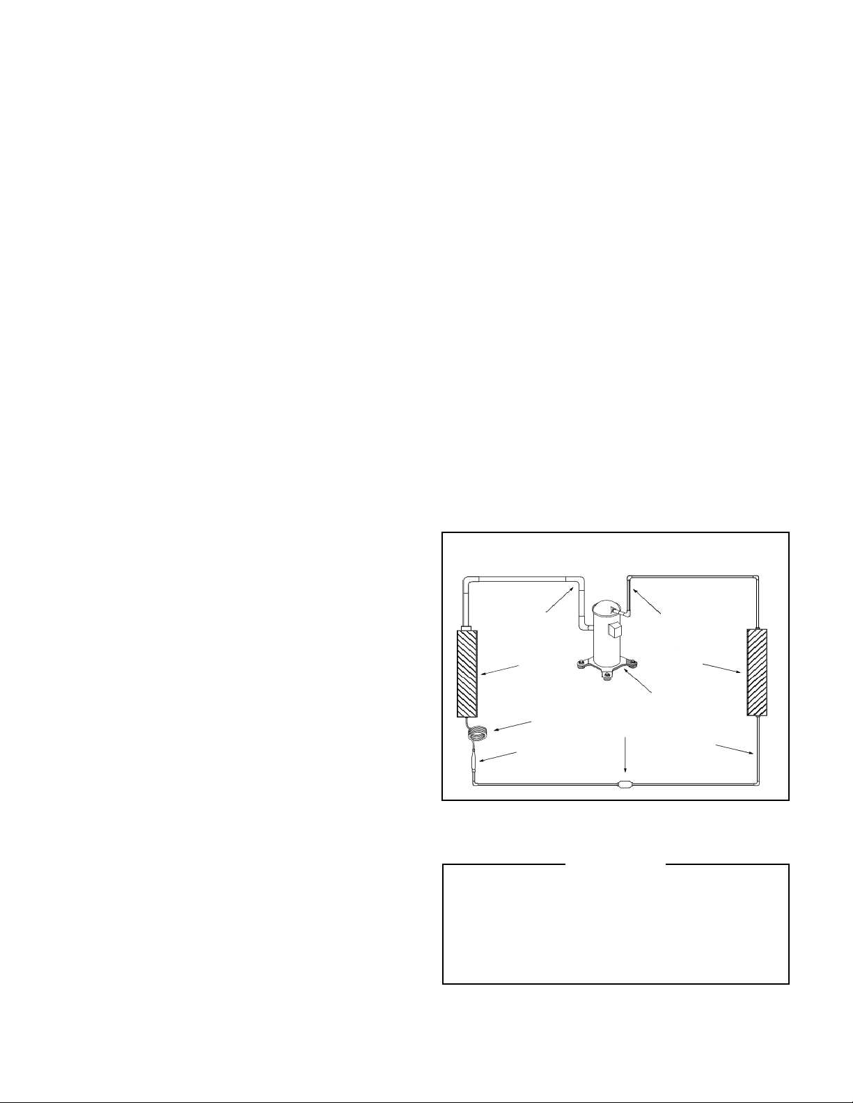
Refrigerant System Components
Suction
Line
Evaporator
Coil
Metering
Device
Refrigerant
Dryer
Refrigerant Drier
SEALED REFRIGERATION SYSTEM REPAIRS
Discharge
Line
Condenser
Coil
Compressor
Liquid
Line
IMPORTANT
ANY SEALED SYSTEM REPAIRS TO COOL-ONLY
MODELS REQUIRE THE INSTALLATION OF A
LIQUID LINE DRIER. ALSO, ANY SEALED SYSTEM
REPAIRS TO HEAT PUMP MODELS REQUIRE THE
INSTALLA TION OF A SUCTION LINE DRIER.
11
Page 12

EQUIPMENT REQUIRED
HERMETIC COMPONENT REPLACEMENT cont’d
1. Voltmeter
2. Ammeter
3. Ohmmeter
4. E.P .A. Approved Refrigerant Recovery System.
5. Vacuum Pump (capable of 200 microns or less vacuum.)
6. Acetylene Welder
7. Electronic Halogen Leak Detector (G.E. Type H-6 or
equivalent.)
8. Accurate refrigerant charge measuring device such as:
a. Balance Scales - 1/2 oz. accuracy
b. Charging Board - 1/2 oz. accuracy
9. High Pressure Gauge - (0 - 400 lbs.)
10. Low Pressure Gauge - (30 - 150 lbs.)
11. V acuum Gauge - ( 0 - 1 000 microns)
EQUIPMENT MUST BE CAPABLE OF:
1. Recovery CFC’s as low as 5%.
2. Evacuation from both the high side and low side of the
system simultaneously.
3. Introducing refrigerant charge into high side of the
system.
4. Accurately weighing the refrigerant charge actually
introduced into the system.
5. Facilities for fl owing nitr ogen through refrigeration
tubing during all brazing processes.
HERMETIC COMPONENT REP LAC EMEN T
The following procedure applies when replacing components
in the sealed refrigeration circuit or repairing refr igerant
leaks. (Compressor, condenser, evaporator, c apillary tube,
refrigerant leaks, etc.)
1. Recover the refrigerant from the system at the process
tube located on the high side of the system by installing
a line tap on the process tube. Apply gauge from
process tube to EPA approved gauges from process
tube to EPA approved recovery system. Recover
CFC’s in system to at least 5 %.
2. Cut the process tube below pinch off on the suction
side of the compressor.
3. Connect the line from the nitrogen tank to the suction
process tube.
4. Drift dry nitr ogen through the system and un-solder
the more distant connection fi rst. (Filter drier, high side
process tube, etc. )
5. Replace inoperative component, and always install a
new fi lter drier. Drift dry nitrogen through the system
when making these connections.
12
6. Pressurize system to 30 PSIG with proper refrigerant and
boost refrigerant pressure to 150 PSIG with dry nitrogen.
7. Leak test complete system with electric halogen leak
detector, correcting any leaks found.
8. Reduce the system to zero gauge pressure.
9. Connect vacuum pump to high side and low side of
system with deep vacuum hoses, or copper tubing.
(Do not use regular hoses.)
10. Evacuate system to maximum absolute holding
pressure of 200 microns or less. NOTE: This
process can be acc elerated by use of heat lamps,
or by breaking the vacuum with refrigerant or dry
nitrogen at 5,000 microns. Pressure system to 5
PSIG and leave in system a minimum of 10 minutes.
Release refrigerant, and proceed with evacuation of
a pressure of 200 microns or less.
1 1 . Break vacuum by charging system from the high side
with the correct amount of liquid refrigeran t specifi ed.
This will prevent boiling the oil out of the crankcase,
and damage to the compressor due to over heating.
NOTE: If the entire charge will not enter the high side, allow
the remainder to enter the low side in small increments while
operating the unit.
12. Restart unit several times af ter allowing pressures
to stabilize. Pinch off process tubes, c ut and solder
the ends. Remove pinch off tool, and leak check the
process tube ends.
SPECIAL PROCEDURE IN THE CASE OF COMPRESSOR
MOTOR BURNOUT
1. Recover all refrigerant and oil from the system.
2. Remove compressor, capillary tube and fi lter drier from
the system .
3. Flush evaporator condenser and all connecting
tubing with dry nitrogen or equivalent, to remove
all contamination from system. Inspect suction and
discharge line for carbon deposits. Remove and clean
if necessary.
4. Reassemble the system, including new drier strainer
and capillary tube.
5. Proceed with processing as outlined under hermetic
component replacement.
ROTARY COMPRESSOR SPECIAL TROUBLESHOOTING
AND SERVICE
Basically, troubleshooting and servicing rotary compressors
is the same as on the reciprocating compressor with only
one main exception:
NEVER , under any circumstanc es, c harge a rotary
compressor through the LOW side. Doing so would
cause permanent damage to the new compressor.
Page 13

REFRIGERANT CHARGING
NOTE: BECAUSE THE RAC SYSTEM IS A SEALED
SYSTEM, SERVICE PROCESS TUBES WILL HAVE TO BE
INSTALLED. FIRST INSTALL A LINE TAP AND REMOVE
REFRIGER ANT FROM SYSTEM. MA KE NECESSARY
SEALED SYSTEM REPAIRS AND VACUUM SYSTEM.
CRIMP PROCESS TUBE LINE AND SOLDER END SHUT.
DO NOT LEAVE A SERVICE VALVE IN THE SE ALED
SYSTEM.
Proper refrigerant charge is essential to proper unit operation.
Operating a unit with an improper refrigerant charge will
result in reduced perfor mance (capacity) and/or effi ciency.
Accordingly, the use of proper charging methods during
servicing will insure that the un it is fu nctioni ng as des ign ed
and that its compressor will not be damaged.
Too much refrigerant (overcharge) in the system is just as
bad (if not worse) than not enough refrigerant ( undercharge) .
They both can be the source of certain compressor failures if
they remain uncorrected for any period of time. Quite often,
other problems (such as low air fl ow across evaporator,
etc. ) are misdiagnosed as refrigerant charge problems. The
refrigerant circuit diagnosis chart will assist you in properly
diagnosing these systems.
An overcharged unit will at times return liquid refrigerant
(slugging) back to the suction side of the compressor
eventually causing a mechanical failure within the compressor.
This mechanical failure can manifest itself as valve failure,
bearing failure, and/or other mechanical failure. The specifi c
type of failure will be infl uenced by the amount of liquid being
returned, and the length of time the slugging continues.
Not enough refrigerant (Undercharge) on the other hand,
will cause the temperature of the suction gas to increase to
the point where it does not provide suffi cient cooling for the
compressor motor. When this occurs, the motor winding
temperature will increase causing the motor to overheat
and possibly cycle open the compressor overload protector.
Continued overheating of the motor windings and/or cycling
of the overload will eventually lead to compressor motor or
overload failure.
METHOD OF CHAR GIN G
The acceptable method for chargi ng the RAC syste m is the
Weighed in Charge Method. The weighed in charge method
is applicable to all units. It is the preferred method to use, as
it is the most accurate.
The weighed in method should always be used whenever
a charge is removed from a unit such as for a leak repair,
compressor replacement, or when there is no refrigerant
charge left in the unit. To charge by this method, requires
the following steps:
1. Install a piercing valve to remove refrigerant from the
sealed system. (Piercing valve must be removed
from the system before recharging. )
2. Recover Refrigerant in accordance with EPA
regulations.
3. Install a process tube to sealed system.
4. Make necessary repairs to system.
5. Evacuate system to 250 - 300 microns or less.
6. Weigh in refrigerant with the propert y quantity of
R-22 refrigerant.
7. Start unit, and verify performance.
8. Crimp the process tube and solder the end shut.
NOTE: In order to access the sealed system it will be necessary to install Schrader type fi ttings to the process tubes
on the discharge and suction of the compress or. Proper refrigerant recovery proce dures need to be adhere d to as
outlined in EPA Regulations. THIS SHOULD ONL Y BE ATTEMPTED BY QUALIFIED SERVICE PERSONNEL.
13
Page 14

REFRIGERANT CHARGING cont’ d
UNDERCHARGED REFRIGERANT SYSTEMS
An undercharged system will result in poor performance (low
pressures, etc.) in both the heating and cooling cycle.
Whenever you service a unit with an under charge of
refrigerant, always suspect a leak. The leak must be repaired
before charging the unit.
T o check for an undercharged system, turn the unit on, allow
the compressor to run long enough to est ablish working
pressures in the system (1 5 to 20 minutes).
During the cooling cycle you can listen c arefully at the exit
of the metering device into the evaporator; an intermittent
hissing and gurgling sound indicates a low refrigerant charge.
NOTE: Heat pump
refrigeration
drawing
Intermittent frosting and thawing of the evaporator is another
indication of a low charge, however , frosting and thawing can
also be caused by insuffi cient air over the evaporator .
Checks for an undercharged system can be made at the
compressor . If the compressor seems quieter than normal,
it is an indication of a low refrigerant charge. A check of the
amper age drawn by the compressor motor should show a
lower reading. (Check the Unit Specifi cation.) After the unit
has run 10 to 15 minutes, check the gauge pressures.
Gauges connected to system with an under charge will have
low head pressures and substantially low suction pressures.
OVERCHARGED REFRIGERANT SYSTEMS
Compressor amps will be near normal or higher. Noncondensables can also cause these symptoms. To confi rm,
remove some of the charge, if conditions improve, system
may be overcharged. If conditions don’t improve, Noncon-
densables are indicated.
Whenever an overcharged system is indi cated, alwa ys mak e
sure that the problem is not caused by air fl ow problems.
Improper air fl ow over the evapora tor coil may indicate some
of the same symptoms as an overcharged system.
An over charge can cause the compres sor to fail, since it
would be “slugged” with liquid refrigerant.
The charge for any system is critical. When the compressor
is noisy , suspect an overcharge, when you are sure that the
air quantity over the evaporator coil is correct. Icing of the
evapora tor will not be encountered because the refriger ant
will boil later if at all. Gauges connected to system will usually
have higher head pressure (depending upon amount of
overcharge ) . Suction pressure should be slightly higher .
14
Page 15

REFRIGERANT CHARGING cont’ d
RESTRICTED REFRIGERANT SYSTEM
A quick check for either condition begins at the evaporator.
With a partial restriction, there may be gurgling sounds at the
metering device entrance to the evaporator . The e vaporator
in a partial restriction could be partially frosted or have an ice
ball close to the entrance of the metering device. Frost may
continue on the suction line back to the compressor.
Often a partial restric tion of any t ype c an be found by feel,
as there is a temperature difference fr om one side of the
restriction to the other.
With a complete restriction, there will be no sound at the meterin g devi ce entr ance. An amper age che ck of th e compre ssor with a partial restriction may show normal current when
compared to the unit specifi cation. With a complete restriction
the current drawn may be considerably less than normal, as
the compressor is running in a deep vacuum (no load). Much
of the area of the condenser will be relatively cool since most
or all of the liquid refrigerant will be stored there.
The following conditions are based primar ily on a system in
the cooling mode.
Troubl eshooting a restric ted refrigeran t system c an
be diffi cult . The following proce d ures are the more
common prob lems and solution s to these proble ms.
There are t wo ty pes of re frig era nt rest ric tio ns: Par tial
restrictions and complete restrictions.
• A par tial restriction allows some of the refrigerant to
circulate through the system.
• With a c omplete restriction there is no circulation of
refrigerant in the system.
• Restricted refrigerant systems display the same
symptoms as a “low-charge condition.”
• When the unit is shut off, the gauges may equal ize very
slowly.
• Gauges c onnected to a completely re stric ted system
will run in a deep vacuum. When the unit is shut off, the
gauges will not equalize at all.
15
Page 16

TROUBLESHOOTING TOU C H T EST CHART: TO SERVIC E REVER SIN G VAL VE S
NORMAL FUNCTION OF VAL VE
VALVE
OPERATING
CONDITION
Normal Cooling
Normal Heating
Valve will not
shift from cool
to heat.
Valve will not
shift from cool
to heat.
Starts to shift
but does not
complete
reversal.
Apparent
leap in heating.
Will not shift
from heat to
cool.
NOTES :
COIL
Compressor
from Compressor
SUCTION TUBE to
DISCHARGE TUBE
Tube to INSIDE
COIL
LEFT Pilot
RIGHT Pilot
Capillary Tu be
Tube to OUTSIDE
Capillary Tu be
* TEMPERATURE OF VALVE BODY
** WARMER THAN VALVE BODY
1 2 3 4 5 6 POSSIBLE C A US ES CORRECTIONS
Hot Cool
Hot Cool
Check Electrical circuit and coil
Check refrigeration charge
Hot Cool Cool,
Hot Cool
Hot Cool
Warm Cool
Hot Warm Warm Hot *TVB Hot
Hot Warm Warm Hot Hot Hot Both ports of pilot open.
Hot Hot Hot Hot *TVB Hot Body da mag e . Replace v a lv e
Hot Hot Hot Hot Hot Hot Both ports of pilot open.
Hot Cool
Hot Cool
Hot Cool
Hot Cool
Hot Cool
Hot Cool
Warm Cool
Cool
as (2)
Hot
as (1)
as (2)
Cool,
as (2)
Cool,
as (2)
Cool,
as (2)
Hot,
as (1)
Hot,
as (1)
Hot,
as (1)
Hot,
as (1)
Hot,
as (1)
Hot,
as (1)
Warm,
as (1)
Hot
*TVB TVB
as (1)
Cool
*TVB TVB
as (2)
MALFUNCTION OF VALVE
No voltage to coil. Repair electrical circuit.
Defective coil. Replace co i l .
Low charge. Repair leak, recharge system.
Pressure differential too high. Recheck system.
Hot,
*TVB Hot
as (1)
Hot,
*TVB *TVB Clogge d p i l o t t u b es .
as (1)
Hot,
as (1)
as (1)
Cool,
as (2)
Cool,
as (2)
Cool,
as (2)
Cool,
as (2)
Cool,
as (2)
Cool,
as (2)
Cool,
as (2)
Hot Hot
Hot,
*TVB Warm Defective Co mp r ess or. Replace co mp re ss or
*TVB *TVB Piston needle on end of slide leaking.
** WVB ** WVB Pilot needle and piston needle leaking.
*TVB *TVB Press u r e d i ffe r ential to o h i gh.
Hot *TVB Dirt in bleeder hole.
Hot *TVB Piston cup leak.
Hot Hot Defectiv e pilo t. Replace valv e .
Warm *TVB Defective compresso r. Replace co mp r ess or
Pilot valve okay. Dirt in one bleeder hole.
Piston cup leak
Both ports of pilot open. (Back seat port did
not close).
Not enough pressure differential at start of
stroke or not enough fl ow to maintain pres-
sure differential.
Body damage. Replace valve
Valve hung up at mid-stroke. Pumping volume of compressor not suffi cient to maintain
reversal.
Clogged pilot tube.
De-energize solenoid, raise head pressure, reenergize solenoid to break dirt
loose. If unsuccessful, remove valve, wash
out. Check on air before installing. If no
movement, replace valve, add strainer to
discharge tube, mount valve horizontally.
Stop unit. After pressures equalize, restart
with solenoid energized. If valve shifts,
reattempt with compressor running. If still
no shift, replace valve.
Raise head pressure, operate solenoid to
free. If still no shift, replace valve.
Raise head pressure, operate solenoid to
free partially clogged port. If still no shift,
replace valve.
Check unit for correct operating pressures
and charge. Raise head pressure. If no
shift, use valve with smaller port.
Raise head pressure, operate solenoid.
If no shift, use valve with smaller ports.
Raise head pressure, operate solenoid.
If no shift, use valve with smaller ports.
Raise head pressure, operate solenoid.
If no shift, replace valve.
Operate valve several times, then recheck.
If excessive leak, replace valve.
Operate valve several times, then recheck.
If excessive leak, replace valve.
Stop unit. Will reverse during equalization
period. Recheck system
Raise head pressure, operate solenoid to
free dirt. If still no shift, replace valve.
Raise head pressure, operate solenoid.
Remove valve and wash out. Check on
air before reinstalling, if no movement,
replace valve. Add strainer to discharge
tube. Mount valve horizontally.
Stop unit. After pressures equalize, restart
with solenoid de-energized. If valve shifts,
reattempt with compressor running. If it
still will not reverse while running, replace
the valve.
16
Page 17

COOLING ONLY ROOM AIR CONDITIONERS: TROUB L E S HOOTING TIPS
Problem Possible Cause Action
Low voltage
T-stat not set cold enough or inoperative
Compressor hums but cuts off on B10 overload
Compressor
does not run
Problem Possible Cause Action
Fan motor
does not run
Open or shorted compressor windings Check for continuity & resistance
Open overload Test overload protector & replace if inoperative
Open capacitor Test capacitor & replace if inoperative
Inoperative system switch
Broken, loose or incorrect wiring
Inoperative system switch Test switch & replace if inoperative
Broken, loose or incorrect wiring Refer to applicable wiring diagram
Open capacitor Test capacitor & replace if inoperative
Fan speed switch open Test switch & replace if inoperative
Inoperative fan motor
Check voltage at compressor. 115V & 230V units
will operate at 10% voltage variance
Set t-stat to coldest position. Test t-stat & replace
if inoperative
Hard start compressor. Direct test compressor. If
compressor starts, add starting components
Test for continuity in all positions. Replace if
inoperative
Refer to appropriate wiring diagrams to check
wiring
Test fan motor & replace if inoperative (be sure
internal overload has had time to reset)
Problem Possible Cause Action
Undersized unit Refer to industry standard sizing chart
Set to coldest position. Test t-stat & replace if
necessary
Use pressure wash or biodegradable cleaning
agent to clean
Close doors. Instruct customer on use of this
feature
Check amperage draw against nameplate. If not
conclusive, make pressure test
Does not cool or
only cools slightly
T-stat open or inoperative
Dirty fi lter Clean as recommended in Owner's Manual
Dirty or restricted condenser or evaporator coil
Poor air circulation Adjust discharge louvers. Use high fan speed
Fresh air or exhaust air door open on applicable
models
Low capacity - undercharge Check for leak & make repair
Compressor not pumping properly
17
Page 18

COOLING ONLY ROOM AIR CONDITIONERS: TROUB L E S HOOTING TIPS
Problem Possible Cause Action
Replace fuse, reset breaker. If repeats, check
Fuse blown or circuit tripped
Unit does not run
Problem Possible Cause Action
Evaporator coil
freezes up
Power cord not plugged in Plug it in
System switch in "OFF" position Set switch correctly
Inoperative system switch Test for continuity in each switch position
Loose or disconnected wiring at switch or other
components
Dirty fi lter Clean as recommended in Owner's Manual
Restricted airfl ow
Inoperative t-stat Test for shorted t-stat or stuck contacts
Short of refrigerant De-ice coil & check for leak
Inoperative fan motor Test fan motor & replace if inoperative
Partially restricted capillary tube
fuse or breaker size. Check for shorts in unit
wiring & components
Check wiring & connections. Reconnect per
wiring diagram
Check for dirty or obstructed coil. Use pressure
wash or biodegradable cleaning agent to clean
De-ice coil. Check temp. differential (delta T)
across coil. Touch test coil return bends for same
temp. Test for low running current
Problem Possible Cause Action
Excessive heat load
Restriction in line
Compressor runs
continually & does
not cycle off
Problem Possible Cause Action
T-stat does not turn
unit off
Refrigerant leak
T-stat contacts stuck
T-stat incorrectly wired Refer to appropriate wiring diagram
T-stat contacts stuck
T-stat set at coldest point
Incorrect wiring Refer to appropriate wiring diagrams
Unit undersized for area to be cooled Refer to industry standard sizing chart
Unit undersized. Test cooling performance &
replace with larger unit if needed
Check for partially iced coil & check temperature
split across coil
Check for oil at silver soldered connections.
Check for partially iced coil. Check split across
coil. Check for low running amperage
Check operation of t-stat. Replace if contacts
remain closed.
Disconnect power to unit. Remove cover of t-stat
& check if contacts are stuck. If so, replace t-stat
Turn to higher temp. setting to see if unit cycles
off
18
Page 19

COOLING ONLY ROOM AIR CONDITIONERS: TROUB L E S HOOTING TIPS
Problem Possible Cause Action
Overload inoperative. Opens too soon
Compressor restarted before system pressures
equalized
Compressor runs for
short periods only .
Cycles on overload
Problem Possible Cause Action
T-stat does not
turn unit on
Low or fl uctuating voltage
Incorrect wiring Refer to appropriate wiring diagram
Shorted or incorrect capacitor
Restricted or low air fl ow through condenser coil
Compressor running abnormally hot
Loss of charge in t-stat bulb
Loose or broken parts in t-stat Check as above
Incorrect wiring Refer to appropriate wiring diagram
Check operation of unit. Replace overload if
system operation is satisfactory
Allow a minimum of 2 minutes to allow pressures
to equalize before attempting to restart. Instruct
customer of waiting period
Check voltage with unit operating. Check for
other appliances on circuit. Air conditioner should
be in separate circuit for proper voltage & fused
separately
Check by substituting a known good capacitor of
correct rating
Check for proper fan speed or blocked
condenser
Check for kinked discharge line or restricted
condenser. Check amperage
Place jumper across t-stat terminals to check if
unit operates. If unit operates, replace t-stat.
Problem Possible Cause Action
Poorly installed Refer to Installation Manual for proper installation
Fan blade striking chassis Reposition - adjust motor mount
Noisy operation
Problem Possible Cause Action
Water leaks into the
room
Compressor vibrating
Improperly mounted or loose cabinet parts
Evaporator drain pan overfl owing Clean obstructed drain trough
Condensation forming on base pan
Poor installation resulting in rain entering the
room
Condensation on discharge grille louvers
Chassis gasket not installed Install gasket, per Installation manual
Downward slope of unit is too steep Refer to installation manual for proper installation
Check that compressor grommets have not
deteriorated. Check that compressor mounting
parts are not missing
Check assembly & parts for looseness, rubbing
& rattling
Evaporator drain pan broken or cracked. Reseal
or replace
Check installation instructions. Reseal as
required
Clean the dirty evaporator coil. Use pressure
wash or biodegradable cleaning agent to clean
19
Page 20

COOLING ONLY ROOM AIR CONDITIONERS: TROUB L E S HOOTING TIPS
Problem Possible Cause Action
Sublimation: When
unconditioned saturated, outside air mixes with
conditioned air, condensation forms on the cooler
Water "spitting"
into room
Problem Possible Cause Action
Excessive moisture
Problem Possible Cause Action
T-stat short cycles
surfaces
Downward pitch of installation is too steep
Restricted coil or dirty fi lter
Insuffi cient air circulation thru area to be air
conditioned
Oversized unit Operate in "MoneySaver" position
Inadequate vapor barrier in building structure,
particularly fl oors
T-stat dif ferential too narrow Replace t-stat
Plenum gasket not sealing, allowing discharge air
to short cycle t-stat
Restricted coil or dirty fi lter
Ensure that foam gaskets are installed in
between window panes & in between the unit &
the sleeve. Also, ensure that fresh air/exhaust
vents (on applicable models) are in the closed
position & are in tact
Follow installation instructions to ensure that
downward pitch of installed unit is no less than
1/4" & no more than 3/8"
Clean & advise customer of periodic cleaning &
maintenance needs of entire unit
Adjust louvers for best possible air circulation
Advise customer
Check gasket. Reposition or replace as needed
Clean & advise customer of periodic cleaning &
maintenance needs of entire unit
Problem Possible Cause Action
Anticipator (resistor) wire disconnected at t-stat
or system switch
Prolonged off
cycles (automatic
operation)
Problem Possible Cause Action
Outside water leaks
Anticipator (resistor) shorted or open
Partial loss of charge in t-stat bulb causing a wide
differential
Evaporator drain pan cracked or obstructed Repair, clean or replace as required
Water in compressor area
Obstructed condenser coil
Fan blade/slinger ring improperly positioned Adjust fan blade to 1/2" of condenser coil
Refer to appropriate wiring diagram
Disconnect plus from outlet. Remove resistor
from bracket. Insert plug & depress "COOL"
& "FAN AUTOMATIC" buttons. Place t-stat to
warmest setting. Feel resistor for temperature. If
no heat, replace resistor
Replace t-stat
Detach shroud from pan & coil. Clean & remove
old sealer. Reseal, reinstall & check
Use pressure wash or biodegradable cleaning
agent to clean
20
Page 21

HEAT / COOL ROOM AIR CONDITIONERS: TROUBLESHOOTING TIPS
Problem Possible Cause Action
Heat anticipator (resistor) shorted (on applicable
models)
Room temperature
uneven
(Heating cycle)
Problem Possible Cause Action
Unit will not defrost
Wide differential - partial loss of t-stat bulb charge Replace t-stat & check
Incorrect wiring
Incorrect wiring Refer to appropriate wiring diagram
Defrost control timer motor not advancing
(applicable models)
Defrost control out of calibration (applicable
models)
Defrost control contacts stuck
Defrost control bulb removed from or not making
good coil contact
Disconnect power to unit. Remove resistor from
t-stat bulb block. Plus in unit & allow to operate.
Feel resistor for heat. If not heat, replace resistor
Refer to appropriate wiring diagram. Resistor is
energized during "ON" cycle of compressor or
fan.
Check for voltage at "TM" & "TM1" on timer. If no
voltage, replace control
If outside coil temperature is 25F or below, &
preselected time limit has elapsed, replace
defrost control
If contacts remain closed between terminals "2"
& "3" of the defrost control after preselected time
interval has passed, replace control
Reinstall & be assured that good bulb to coil
contact is made
Problem Possible Cause Action
Exhaust or fresh air door open
Dirty fi lter Clean as recommended in Owner's Manual
Unit undersized
Does not heat
adequately
Outdoor t-stat open (applicable models)
Heater hi-limit control cycling on & off
Shorted supplementary heater Ohmmeter check, approx. 32-35 ohms
Incorrect wiring Check applicable wiring diagram
Check if operating properly . Instruct customer on
proper use of control
Check heat rise across coil. If unit operates
effi ciently , check if insulation can be added
to attic or walls. If insulation is adequate,
recommend additional unit or larger one
T-stat should close at 38°F. Check continuity of
control. If temperature is below 38°F, replace
control
Check for adequate fan air across heater. Check
control for open at 160°F & close at 150°F
21
Page 22

HEAT / COOL ROOM AIR CONDITIONERS: TROUBLESHOOTING TIPS
Problem Possible Cause Action
Incorrect wiring Refer to applicable wiring diagram
Defective solenoid coil Check for continuity of coil
Unit cools when
heat is called for
Reversing valve fails to shift
Inoperative system switch Check for continuity of system switch
Problem Possible Cause Action
Heating capillary tube partially restricted
Cooling adequate,
Check valve leaking internally
but heating
insuffi cient
Reversing valve failing to shift completely;
bypassing hot gas
Block condenser coil & switch unit to cooling.
Allow pressure to build up in system, then
switch to heating. If valve fails to shift, replace
valve.
Check for partially starved outer coil. Replace
heating capillary tube
Switch unit several times from heating to
cooling. Check temperature rise across
coil. Refer to specifi cation sheet for correct
temperature rise
De-energize solenoid coil, raise head
pressure, energize solenoid to break loose.
If valve fails to make complete shift, replace
valve.
TROUBLESHOOTING CHART — COOLING
REFRIGERANT SYSTEM DIAGNOSIS – HEATING
Low Suction Pressure High Suction Pressure Low Head Pressure High Head Pressure
Low Load Conditions High Load Conditions Low Load Conditions High Load Conditions
Low Air Flow Across High Air Flow Across Refrigerant System Low Air Flow Across
Indoor Coil Indoor Coil Restriction Outdoor Coil
Refrigerant System Reversing Valve not Reversing Valve not
Restriction Fully Seated Fully Seated
Undercharged Overcharged
Moisture in System Defective Compressor Defective Compressor
Undercharged
in System
Overcharged
Noncondensables (air)
22
Page 23

TROUBLESHOOTING CHART — HEATING
REFRIGERANT SYSTEM DIAGNOSIS – HEATING
Low Suction Pressure
Low Airfl ow
Across Outdoor Coil
Refrigerant System
Restriction
Undercharged Overcharged
Moisture in System Defective Compressor
High Suction Pressure
Outdoor Ambient Too High
for Operation in Heating
Reversing Valve not
Fully Seated
ELECTRICAL TROUBLESHOOTING CHART — HEAT PUMP
Low Head Pressure
Refrigerant System
Reversing Valve not
Defective Compressor
HEAT PUMP
Restriction
Fully Seated
Undercharged
High Head Pressure
Outdoor Ambient Too High
For Operation In Heating
Low Airfl ow Across
Indoor Coil
Overcharge d
Noncondensab les (air)
Is Line Voltage
Present at the Solenoid
YES
Is the Solenoid Coil Good?
YES
Reversing Valve Stuck
Replace the Reversing Valve
SYSTEM COOLS WHEN
HEATING IS DESIRED.
NO
NO
Is the Selector Switch
Set for Heat?
Replace the Solenoid Coil
23
Page 24

MODELS
XQ05L10-A,B; XQ06L10-A,B,C,D; XQ08L10-A,B; XQ10L10-A,B; XQ12L10-A,B
24
Page 25

MODELS
KS10L10-A, RS10L10-A, KS12L10-A, KS12L30-A, KS15L10-A, RS15L10-A, RS16L30-A,
RM18L30-A, KM18L30-A, KM21L30-A, RM24L30-A, KM24L30-A
25
Page 26

MODELS
SS08L10-A/B, SS10L10-A/B, SS12L10-A/B; SS12L30-A/B, SS14L10-A/B,
SS16L30-A/B, SM18L30-A/B, SM21L30-A/B, SM24L30-A/B
26
Page 27

MODEL
SL36L30-A
27
Page 28

MODEL
SL28L30-A
28
Page 29

MODELS
SL36L30-B
29
Page 30

MODEL
EQ08L1 1 -A
30
Page 31

MODELS
ES12L33-A, ES16L33-A, EM18L34-A, EM24L35-A
31
Page 32

MODEL
EL36L35-A
32
Page 33

MODEL
YS09L10-A, YS09L10-B
33
Page 34

MODELS
YS13L33-A, YM18L34-A
34
Page 35

MODELS
YL24L35-A
35
Page 36

Friedrich Air Conditioning Co.
Post Office Box 1540 • San Antonio, Texas 78295-1540
4200 N. Pan Am Expressway • San Antonio, Texas 78218-5212
(210) 357-4400 • FAX (210) 357-4480
www.friedrich.com
Printed in the U.S.A.
RAC-Svc-07 (4-07)
 Loading...