

Page 1
V
)
m
A
V
®
arts
M
l
anua
ert-I-Pak
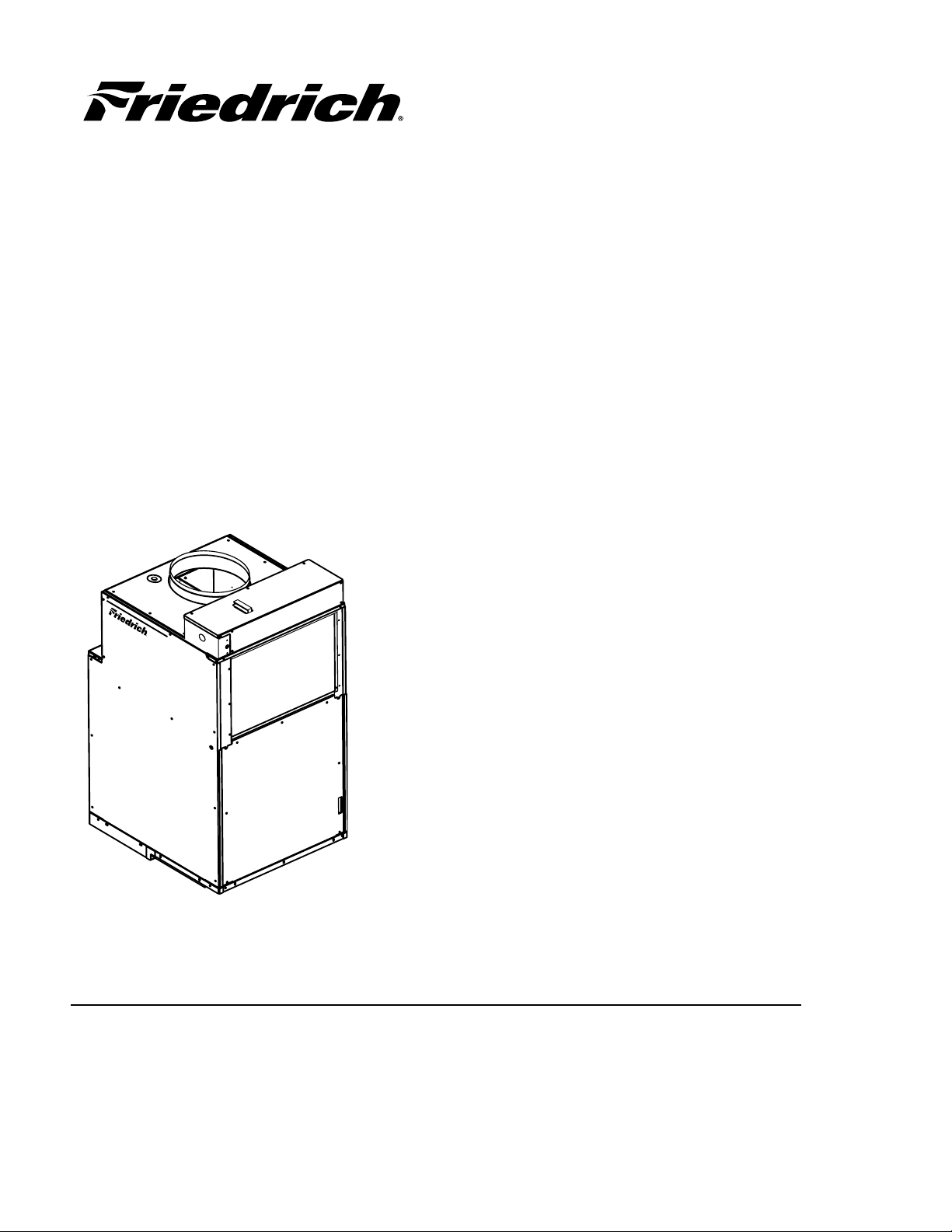
Single Package V ertical Air Conditioning Syste
Series / 24,000 BTU/h
PAK2T-07 (12-07
Page 2
T
able of Contents
de
................................................................................................................
2
t
3
....................................................................................................................................
4
t
5
6
E
A S
5
3
5
*
**
K 50 RT H-A
E
S
n
9000
.
V
08/230
A Series (Btu/h)
()
0
S
A
Cabinet
S
S
V
t
p
y.
E
l Number Identifi cation Gui
ontrol Box Diagram and Parts Lis
efrigeration Diagram
efrigeration Parts Lis
Blower Assembly Diagram
Blower Assembly Parts List ............................................................................................................................
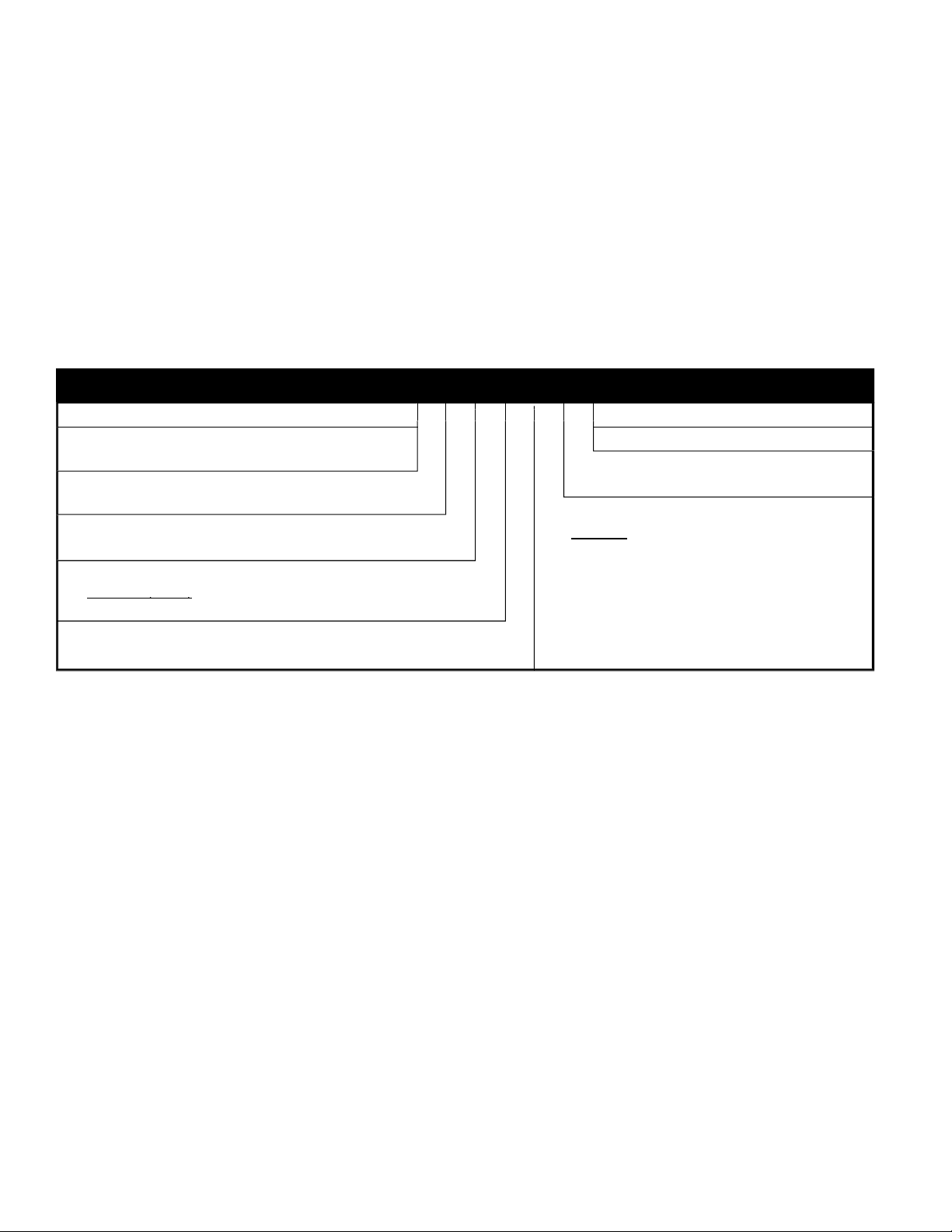
Vert-I-Pak® Model Identifi cation Guide
ERIE
=Vertical Series
E =Cooling with elect ric hea
H =Heat Pum
ESIGN SERIE
= 32"/47"
NOMINAL CAPACITY
24 = 24,00
OLTAGE
K = 2
V-1Ph-60Hz
OPTION
T = Stan dard Re mote Op er a tio
ELECTRIC HEATER SIZ
eries
= 2.5 KW
2
4 = 3.4 KW
0 = 5.0 KW
75 = 7.5 KW
efer to electrical data chart for heater/unit compatibilit
* Not available on
** 24000 BTU only.
BTU models
COMPR. COD
N GI NEER ING COD
Page 3
3
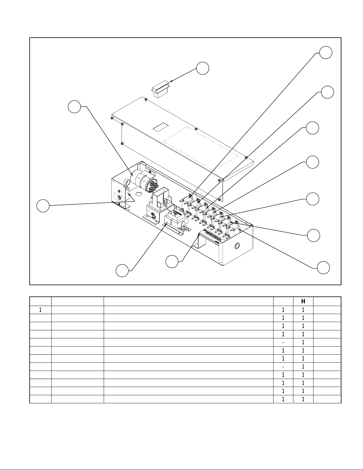
Control Box Assembl
y
.
S
8
0
Fused Disconnect
2
.
3
2
1
Terminal Board
C
5
8
1
y)
6
3
C
y
3
y
8
3
y
9
3
3
3
3
6
1
7
4
8
9
10
5
ART NO
000760
1056899 Transformer 208/230V Prim. 24V Sec
504320
61080529
011060
6008403
6008403
6008403
6008403
10 6008403
6008403
6008403
3
2
ESCRIPTION
n
apacitor 40/7.5 MFD @ 400 V
efrost Thermostat (Heat Pump Onl
ompressor Rela
an Rela
eversing Valve Rela
eat Relay 2.5/3.4/5.0 KW
eat Relay 2.5/3.4/5.0 KW
eat Relay 7.5/10 KW
eat Relay 7.5/10 KW
11
12
NOTE
Page 4

Refrigeration
14
25
27
26
19
23
24
21
13
15
16
31
32
20
17
18
Page 5
5
.
N
S
1
3
2
C
8
l
5
8
O
5
8
1
O
t
6
2
2
V
7
2
C
e
8
1
C
e
2
8
0
3
C
e
8
0
7
C
e
9
8
an
20
8
ase Pan
21
2
3
)
22
3
C
e
23
8
0
2
8
r
25
8
26
8
1
l
27
8
ost
8
t
29
1
S
8
ube
31
8
0
g
32
8
1
ase Med
8
0
t
14
1
1
1
1
1
1
1
1
ART NO
5024925
ompressor
ESCRIPTIO
NOTE
0103400 Indoor Coi
0101200
010120
5022032
5022080
5076000
0376051
376047
376050
0100300
utdoor Coil
utdoor Coil Sea Coas
eversing Valve Kit w/ Solenoid Coil
eversing Valve Solenoid Coil 230
heck Valv
ap tub
ap tub
ap tub
rain P
0115222 B
105902
6017990
011270
4
0101600
Low Ambient Control (Suction Line Thermostat
ondensate Valv
igh Pressure Switch
ight Post Uppe
0101500 Left Post Upper
010620
Inner Wal
0101300 Lower Left P
0101400 Lower Right Pos
6183480
0108500
011350
011350
011360
trainer
rain Pan T
Bracket Base Lon
Bracket B
Bracket Base Shor
N/S=Not Shown
Page 6

6
Blower Assembl
y
43
42
57
44
45
54
40
51
47
46
41
50
49
48
52
53
Page 7
PART NO
.
N
S
0
8
C
1
8
C
x
2
8
3
8
)
4
8
5
8
et
2
2
6
8
1
y
7
8
7
8
1
7
8
2
7
8
3
7
8
4
/S
8
1
/S
8
/S
8
8
8
C
9
t
50
8
d
51
e
52
8
ed
53
8
l
54
8
/S
8
et
/S
8
t
57
8
C
/S
C
t
/S
r
4
/S
3
V
4
4
4
4
4
4
4
4
4
4
4
4
N
N
N
4
4
N
N
N
N
N
0103300
0102000
0113200 Top Cover
0103200
0106900
0103600
010670
0102290
010229
010229
010229
010229
011460
0114600
0114602
0102170
25014400
0101000
60542007 16” Plastic Fan Blad
0106600
0106400
0106500
0102600
0113300
0001800
20709185
01336910
6108054
ontrol Box Cover
ontrol Bo
lower wheel and housing (Not Separate
lower Motor
lower Brack
Insulated Top Assembl
eater Assembly 2.5 KW
eater Assembly 3.4 KW
eater Assembly 5.0 KW
eater Assembly 7.5 KW
eater Assembly 10.0 KW
imit (Seconday) 2.5 / 3.4 / 5.0 / 7.5 / 10.0 KW
imit (Primary) 2.5 / 3.4 / 5.0 KW
imit (Primary) 7.5 / 10.0 KW
ondenser Fan Motor
tor Moun
an Shrou
k Panel Insulat
ight Side Pane
eft Side Panel
ter Brack
eater Suppor
ollar
apacitor Bracke
lower Space
lower Capacitor 15/5/ MFD @ 370
ESCRIPTIO
NOTE
2.5 KW Models
3.4 KW Models
5.0 KW Models
7.5 KW Models
10.0 KW Models
4
N/S=Not Shown
Page 8

V
)
se Factory Certifi ed Parts
.
CO.
0
w
FRIEDRICH AIR CONDITIONING
ost Office Box 1540 · San Antonio, Texas 78295-1540
4200 N. Pan Am Expressway · San Antonio, Texas 78218-5212
210) 357-4400 · Fax (210) 357-448
ww.friedrich.com
rinted in the U.S.A.
PAK2T-07 (12-07
 Loading...