

Page 1
Quick Guide
Control system FC
FCDA - FC Direct, FCSA - FC Smart
FCPA - FC Pro, FCBA - FC Building
EN
Page 2
EN
FC Frico Control - Quick guide
FC Control system
The air curtain must be supplemented with a control system.
FC Control system helps to create many smart and energy saving features. In addition to our
four packages, components can be added to expand and customize the system.
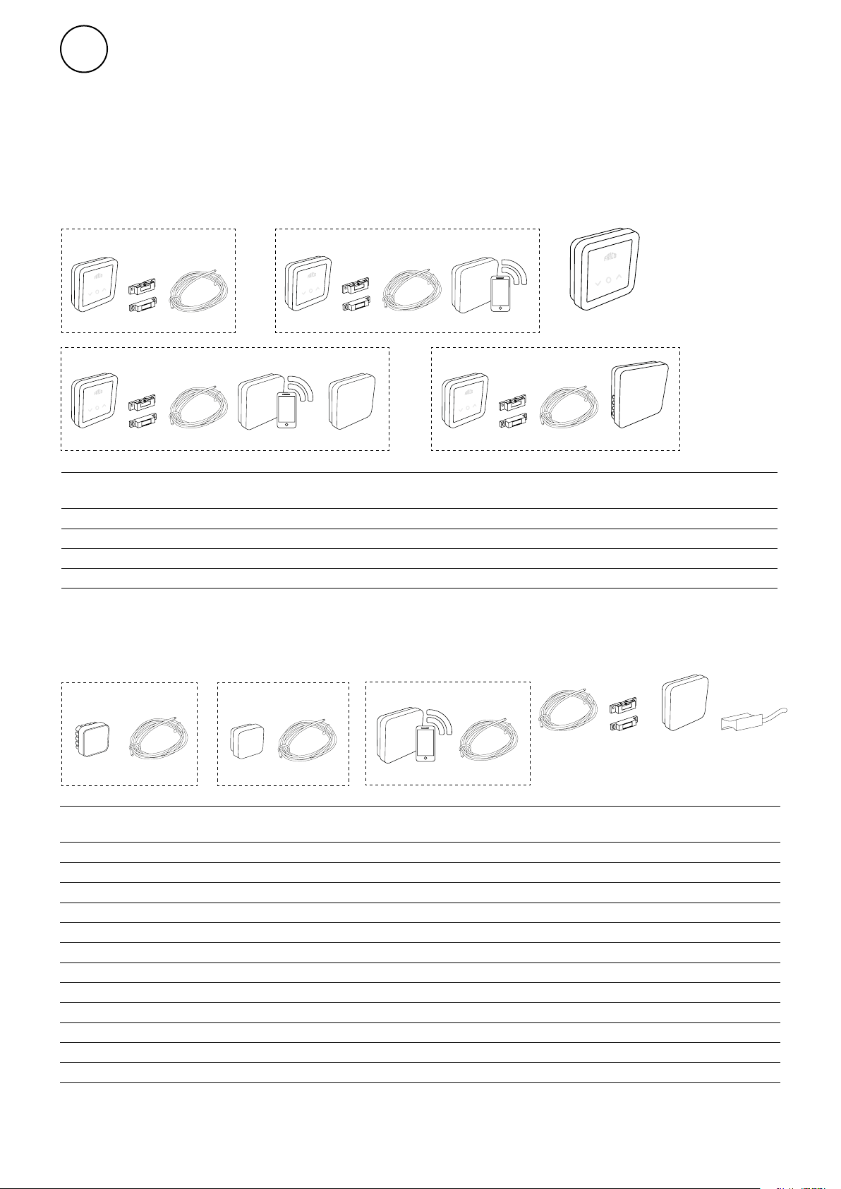
FCDA - FC Direct FCSA - FC Smart
FCBC05FCDCFCCF
FCBC10FCDCFCCF
FCLAP
FCPA - FC Pro FCBA - FC Building
Item
number
74684
74685
74686
74687
FCBC10FCDCFCCF
Type Description Dimensions
FCDA
FCSA
FCPA
FCBA
FCLAP
FC Direct, rst level control system
FC Smart, second level control system
FC Pro, third level control system
FC Building, BMS system
FCTXRF
Control system content and accessories
FCRTX
FCOTX
FCLAP
FCCF control panel
FCBC10FCDCFCCF
FCBAP
89x89x26 mm (FCCF)
89x89x26 mm (FCCF)
89x89x26 mm (FCCF)
89x89x26 mm (FCCF)
FCSC10
Item
number
74694
74695
74699
74718
74719
74720
74721
74722
17495
74703
74702 FCWTA
Type Description Dimensions
FCRTX
FCOTX
FCLAP
FCBC05 5 m
FCBC10 10 m
FCBC25 25 m
FCSC10 10 m
FCSC25 25 m
FCDC
FCTXRF*
FCBAP 149x149x43 mm
FCSC10
External room temperature sensor
Outdoor temperature sensor
Local access point for extra sensors and extended range
Extra communication cable, 5 m
Extra communication cable, 10 m
Extra communication cable, 25 m
Extra sensor cable, 10 m
Extra sensor cable, 25 m
Door contact
Indoor/outdoor wireless sensor (for FC Smart, FC Pro)
Return water temperature sensor
Building access point
FCBC10
FCBC
FCSC
FCDC FCWTAFCTXRF
39x39x23 mm
39x39x23 mm
89x89x26 mm
89x89x26 mm
*The wireless sensor can be set up as outdoor or indoor sensor by a switch inside the sensor.
2
Page 3
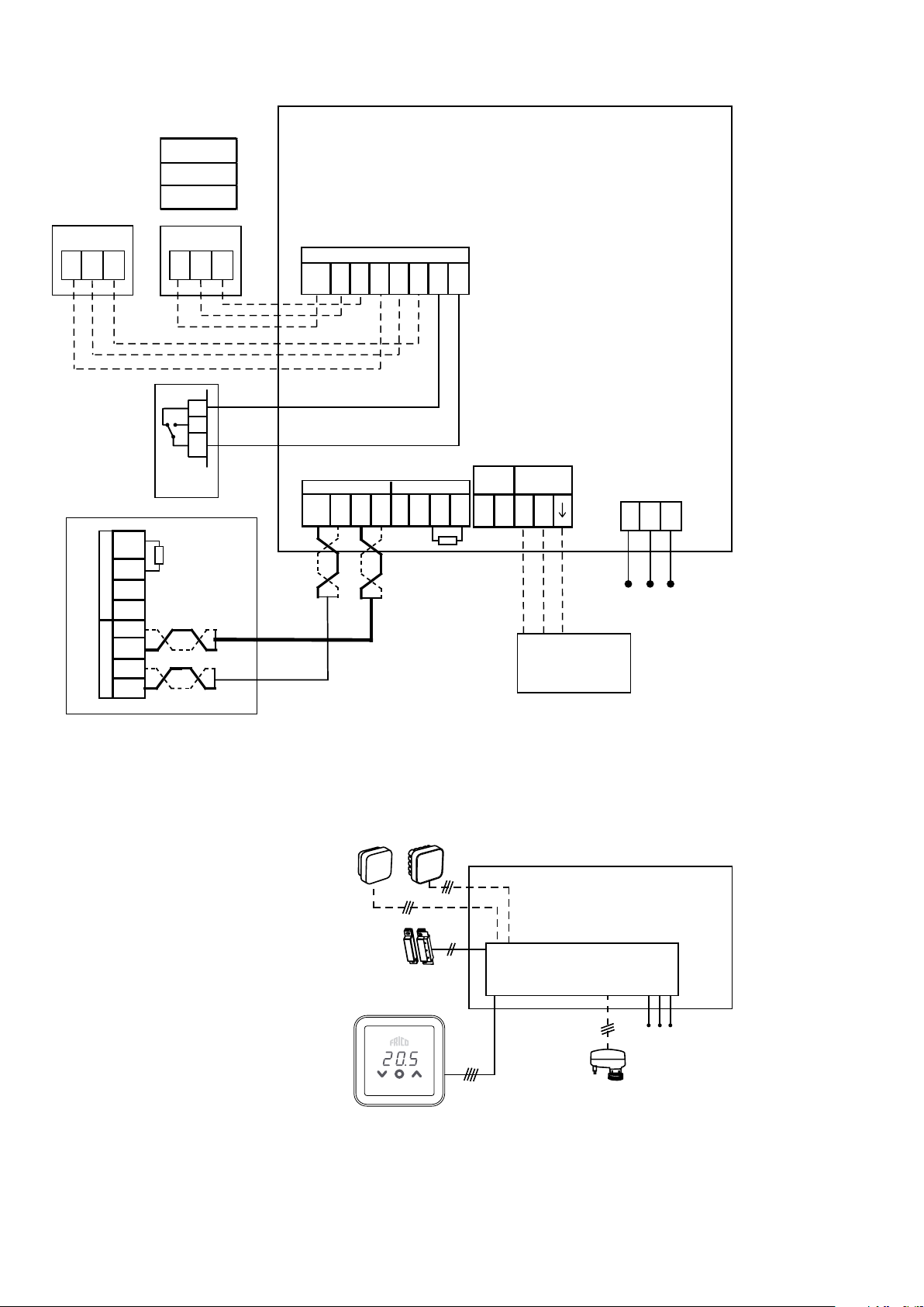
FC Direct - FCDA
FCRTX
FCOTX
Sensor
FCRTX
FCOTX
FC Frico Control - Quick guide
Sensor
G12
+12V
BUS 2
GND
+12V
BUS 1
GND
LO
LO
Sensor
G12
FCDC
NONC
Com
A1 A2 B1 B2
GND
BUS 1 BUS 2
GND
+12V
GND
HI
LO
D1 D2
Actuator
WTA
E1 E2-+
HI
+12V
LO
GND
24V
PC Board
inside air
curtain
PELN
Control
Panel
HI
BLK
GRY
RED
230V~
HI
SDM
(VPFC/VMFC)
FCDC
Control Panel
PC Board inside
air curtain
230V~
SDM
(VPFC/VMFC)
3
Page 4
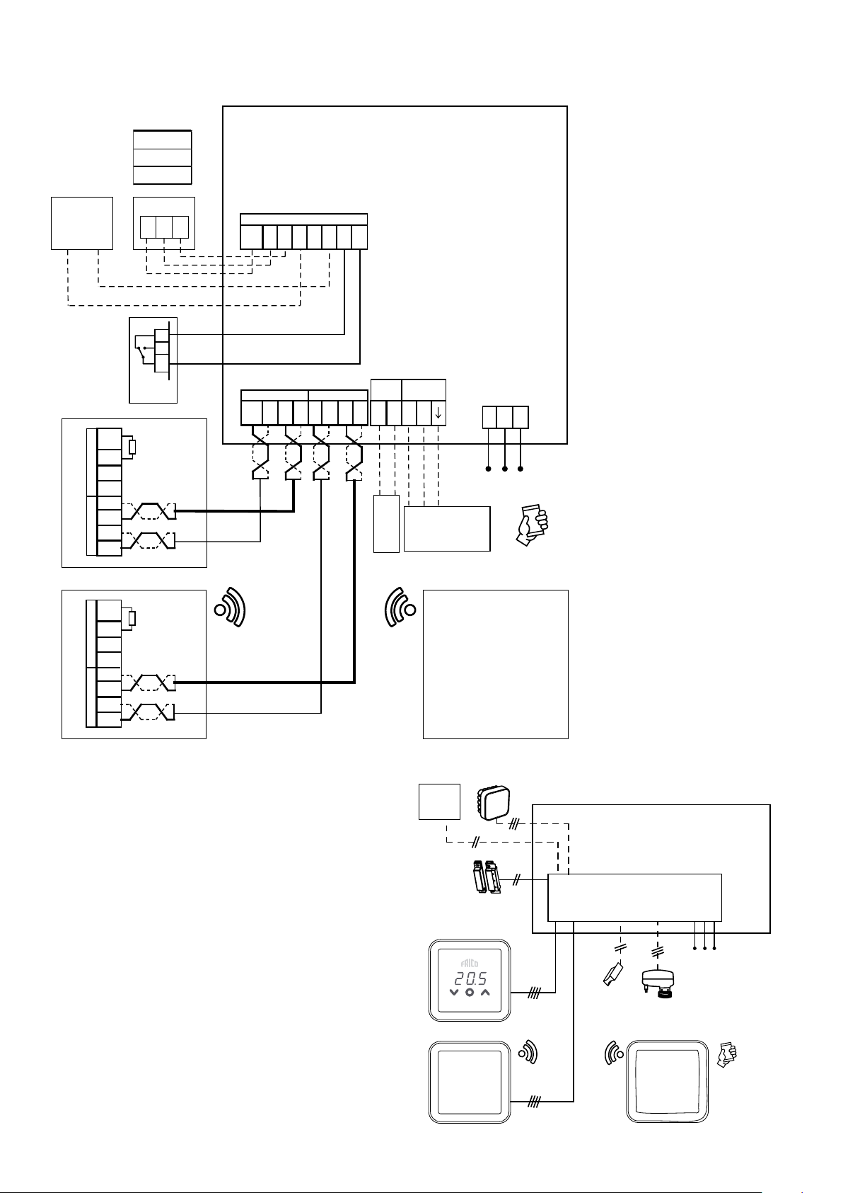
FC Smart - FCSA
FCOTX
PC Board
inside air
curtain
PELN
230V~
Sensor
FCRTX
FC Frico Control - Quick guide
Config
input*
+12V
BUS 2
GND
+12V
BUS 1
GND
+12V
BUS 2
GND
+12V
BUS 1
GND
Sensor
G12
NONC
Com
FCDC
LO
HI
Control
Panel
A1 A2 B1 B2
GND
GND
GND
BUS 1 BUS 2
HI
LO
+12V
D1 D2
Actuator
WTA
E1 E2-+
HI
+12V
LO
GND
24V
BLK
RED
PC Board
inside air
curtain
PELN
GRY
230V~
LO
HI
FCWTA
LO
HI
FCLAP
SDM
(VPFC/VMFC)
*
Set up in
Setup Guide
*
LO
HI
Sensor
Config
input*
Set up in
Setup Guide
PC Board inside
FCDC
air curtain
230V~
FCWTA
SDM
Control Panel
(VPFC/VMFC)
*
Set up in
Setup Guide
FCLAP
4
Page 5
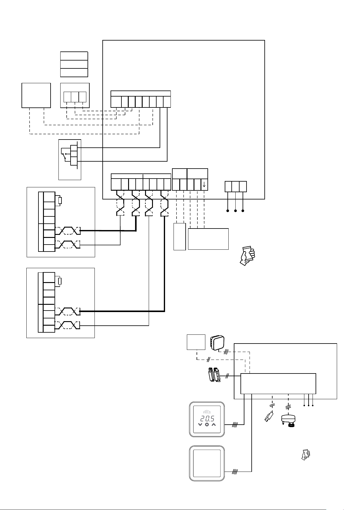
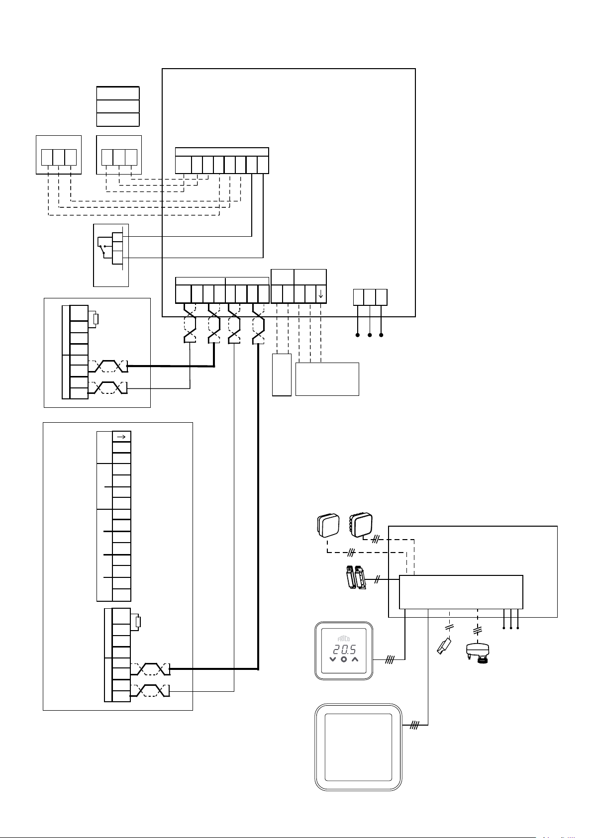
FC Pro - FCPA
FCOTX
Sensor
FCRTX
FC Frico Control - Quick guide
Config
input*
+12V
BUS 2
GND
+12V
BUS 1
GND
+12V
BUS 2
GND
+12V
BUS 1
GND
Sensor
G12
NONC
Com
FCDC
LO
HI
LO
HI
Control
Panel
A1 A2 B1 B2
GND
GND
GND
BUS 1 BUS 2
HI
LO
+12V
D1 D2
Actuator
WTA
24V
E1 E2-+
HI
+12V
LO
BLK
RED
GND
SDM
(VPFC/VMFC)
FCWTA
GRY
PC Board
inside air
curtain
PELN
230V~
*
Set up in
Setup Guide
LO
HI
LO
HI
FCLAP
FCTXRF*
Sensor
Config
input*
FCDC
Control Panel
FCLAP
PC Board inside
air curtain
230V~
FCWTA
SDM
(VPFC/VMFC)
*
Set up in
Setup Guide
FCTXRF*
5
Page 6
FC Building - FCBA
FCRTX
FCOTX
Sensor
FCRTX
FCOTX
FC Frico Control - Quick guide
Sensor
G12
BUS 2
BUS 1
LO
HI
+12V
GND
LO
HI
+12V
GND
Sensor
G12
Control
Panel
PC Board
A1 A2 B1 B2
GND
NONC
Com
BUS 1 BUS 2
HI
GND
+12V
GND
LO
D1 D2
Actuator
WTA
24V
E1 E2-+
HI
+12V
LO
BLK
RED
SDM
S
(VPFC/VMFC)
FCWTA
GND
inside air
curtain
PELN
GRY
230V~
Modbus
Alarm RS485
OUTPUT
RunInd
OFF
R.Temp
INPUT
S.Temp
FanSpd
LO
HI
+12V
BUS 2
GND
LO
HI
+12V
BUS 1
GND
+
-
E1 E2
E1 E2
E1 E2
E1 E2
E1 E2
E1 E2
FCBAP
FCDC
Control Panel
PC Board inside
air curtain
230V~
FCWTA
SDM
(VPFC/VMFC)
FCBAP
6
Page 7

FC Frico Control - Quick guide
Termination at PC Board
BUS 1 BUS 2
HI
LO
GND
+12V
BUS 1 BUS 2
HI
LO
GND
+12V
HI
GND
+12V
HI
LO
LO
GND
+12V
BUS 1BUS 2
HI
LO
GND
+12V
HI
LO
GND
+12V
To reduce the risk of interference, the communication BUS should be terminated at each end, i.e. in the units
that are located at the start and at the end of the BUS respectively. On delivery, all buses are pre-connected
with a 120 Ohm resistor between terminals HI and LO on BUS2. When making further connections, remove the
resistor. As an alternative to resistance, the termination switch on the board can be set to the "ON" position.
7
Page 8

EN
FC Frico Control - Quick guide
Start up
1. Check that all components and accessories are
enclosed.
2. Assemble and connect system, consult wiring
diagrams.
3. Power-up the system.
4. The system automatically identifies all components,
even when they are added at a later stage.
5. Connecting a new product must always be made
with the power off.
System solution
A system consists of a control panel, FCCF, as well as an
optional number (1-63) of units (air curtains, access points
or control panels) and sensors. The set-point temperature
and the fan settings for the system are selected on the
control panel.
The control panel houses a built-in temperature sensor
which can be used, alternatively the products or zones are
fitted with external room temperature sensors that have
better sensor positioning for local temperature control.
A. System without external room sensors
The control panel's temperature sensor is
controlling together with the inlet sensor in
each product.
B. System with one external room sensor
One external room temperature sensor in
the system controls all products, together
with the inlet sensor in each product.
C. System with several products with
external room sensors connected to each
product
External room temperature sensors
control each product, together with the
inlet sensor in each product.
D. System with several products, of which,
at least two products have external room
sensors and at least one product does not
have an external room sensor
External room temperature sensors control
each product it is connected to together with
the inlet sensor in each product. Products
without sensors are controlled by the control
panel's temperature sensor together with the
inlet sensor in each product.
Heating blocked dependent on outdoor temperature
With outdoor temperature information (FCOTX / FCTXRF
/ outdoor temperature signal in FCBAP), heating is
automatically blocked when the outdoor temperature
exceeds 15 °C. The set point can be changed and this
function can be deactivated, see Settings.
8
Page 9

Control panel
Overview
FC Frico Control - Quick guide
EN
7
2
4
3
5
8
Keypad
1 Increase
2 Decrease
3 Menu / OK / Confirm
4 Fan
6
1
5 Cancel / Back
4 and 5 appear after pressing twice on menu
button.
Screen
6 Current room temperature (standby mode) /
Set point temperature (active mode)
Ambient air curtain: Fan setting
Indicators
7 Operating mode
8 Status
Indicator Operating Mode (left-hand LED)
Colour (LED)
OFF
White
White flashing
Green
Green flashing
Orange
Purple
Cyan
Operating mode
Normal mode
Comfort mode
Comfort mode - temporary
Reduced (night mode)
Reduced (night mode) - temporary
Timer (activated in app)
Saving mode (activated in app)
Presence mode (activated in app)
During start-up, the text Inlt appears on
screen, then the current room temperature is
displayed.
When the screen is in standby mode, the light
intensity is reduced. Pressing any button will
simply display the set point temperature.
The FC control is delivered with preset values.
The preset set point temperature is 21 °C
and can be easily adjusted using the up/down
arrows.
Indicator Status (right-hand LED)
Colour (LED)
White
OFF
Red flashing
Purple
Display lock
Press and hold (2 sec) Quick command
+
Status
Heat on
Heat off
Alarm
Heating blocking
Display lock on/off
9
Page 10

EN
FC Frico Control - Quick guide
Fan speed when door is open
Press twice to activate keypad and hidden
buttons.
Press to set fan speed
Set the fan speed: 0-100-Auto / 0-3-Auto.
Auto requires outdoor temperature
information (FCOTX / FCTXRF / outdoor
temperature signal in FCBAP).
Fan menu
Press twice to activate keypad and hidden
buttons.
Press and hold for 2 seconds.
Home screen
Browse between the menu options.
Confirm
or
Exit without saving
See the table on the following page for the possible
choices.
10
Page 11

Fan menu
FC Frico Control - Quick guide
EN
Functions Menu
options
FAnH
FAnL 0
FAnC
Arun
Maximum fan speed in Auto mode.
Minimum fan speed in Auto mode.
Fan speed closed door.
After run when door closes.
settings
100 or 3
(100% or
step 3)
25 or 1
(25% or
step 1)
Auto
Description Default
Increase/decrease with up/down
arrow. Confirm with OK.
Increase/decrease with up/down
arrow. Confirm with OK.
Increase/decrease with up/down
arrow. Confirm with OK. Fan
speed if there is a need for heat
when door is closed. Set to 0 if
the air curtain should be off at
closed door.
Increase/decrease with up/down
arrow. Confirm with OK. Auto OFF - 10 - 20 ... - 500s
11
Page 12

EN
User menu
Press to activate keypad.
Press and hold for 2 seconds.
Home screen
Browse between the menu options.
FC Frico Control - Quick guide
Confirm
or
Exit without saving
See the table on the following page for the possible
choices.
12
Page 13

User menu
FC Frico Control - Quick guide
EN
Functions Menu
options
dAtE -
tHi 21 °C
tLo 18 °C
Prog
HEAt
For week program.
Set the following:
- year
- month
- day
- time (00:00)
For week program. Set the desired room
temperature (set point temperature) for
comfort mode.
For week program. Set the desired room
temperature (set point temperature) for
reduced mode.
Weekly program, see separate section.
Switch heating on/off.
settings
(off)
(function
not
activated)
On (on)
Description Default
Increase/decrease with up/down
arrow. Confirm each step with OK.
Increase/decrease with up/down
arrow. Confirm with OK.
Increase/decrease with up/down
arrow. Confirm with OK.
Switch between (OFF) and P1-P9
with up/down arrow. Confirm
with OK.
Switch between (On) and (OFF)
with up/down arrow. Confirm
with OK.
AL A -
AL H -
OFF -
SEt -
CLr -
Display active alarm.
Display alarm history.
Switch off the system. To switch off the system, select
Change settings, see separate section
Settings.
Factory reset. Resets values to factory
settings.
Switch between alarms with up/
down arrow. To see the serial
number for an alarm, press OK.
If no alarm: no A.
Switch between alarms with up/
down arrow. To see the serial
number for an alarm, press OK.
If no alarm: no A.
(OFF) using OK. Wait 10 sec.
The system is then switched on
by pressing OK and selecting
(On) with up/down arrow and
confirming with OK.
Press OK. Select (YES), by
keeping OK depressed for 2
seconds (countdown).
LAP -
Pairing with local access point. Follow set
up guide in mobile app to pair it with the
FC system.
Press OK. A pairing period of
120 s starts.
13
Page 14

EN
FC Frico Control - Quick guide
Week program
The FC has nine preset weekly programs (P1P9) and one customized (P0). Customized
program is possible via FC Smart and FC Pro
through the mobile app.
To activate weekly program, the following must be
set in the user menu:
- Date (dAtE)
- Temperature, comfort mode (tHi)
- Temperature, reduced mode (tLo)
The adaptive start function allows the control
to learn when it needs to start in order to
attain a given set point temperature at a given
time of the day in the environment in which
it is used. This function can be deactivated
(see Settings menu).
Preset programs
Setting week programs
Weekly program is selected and activated in User
Menu:
Press to activate keypad.
Press and hold for 2 seconds.
Browse to Prog.
Confirm
Selection of preset program P0/P1 - P9
Select P0/P1-P9.
Description
P1 05:30 - 08
P2 06:30 - 10
P3 06 - 09
P4 06 - 22
P5 17 - 23
P6 06 - 18
P7 09 - 21
P8 09 - 22
P9 09 - 18
*) Other times: Reduced (night mode)
Residence
Residence,
late
Residence,
short
Residence,
day only
Weekend
Office
Office, late
Shop, late
Shop
Comfort mode
*
Mon-Fri:
Sat-Sun:
Mon-Fri:
Sat-Sun:
Mon-Fri:
Sat-Sun:
Mon-Sun:
Fri:
Sat-Sun:
Mon-Fri:
Mon-Fri:
Mon-Fri:
Sat-Sun:
Mon-Fri:
Sat-Sun:
17 - 22
07 - 23
19 - 23:30
07:30 - 23:30
16 - 23
07 - 23
07 - 23
09 - 20
09 - 14
Confirm to start the program.
Temporarily override the weekly program
It is easy to temporarily disregard the set point
temperature which is preset in the weekly program.
Set the desired temporary set point
temperature.
Confirm
The temporary set point temperature will apply until
the next program step.
Power failure
Note! A power loss longer than 7 days may
require an adjustment of time and date.
The week program is affected if the clock is
not correctly set.
14
Page 15

Settings
Settings are changed in User Menu:
Press to activate keypad.
FC Frico Control - Quick guide
EN
Press and hold for 2 seconds.
Browse to SEt.
Confirm
Enter password using up/down arrows, confirm
each digit with OK. Password: 1932.
Settings - General
#
602 15 (%) 0-100
Functions Default settings
After run speed - fixed
Enter the number for the setting that will be
changed using up/down arrows, confirm each digit
with OK. See table.
Description
Select desired value according to table.
Confirm
Fan speed in fixed after run mode.
592 15 (%) 0-50
690 1
691 0
687
438
After run speed - Auto
low
Door contact polarity
Door contact reset
Door contact Common control
Daylight saving/
summer time and
winter time.
Low fan speed in automatic after run mode.
0 (normally open) / 1 (normally closed)
If other type of signal is used.
normally closed = short circuit - fan stops
normally open = short circuit - fan runs
0 (no door contact has been detected) / 1 (door
contact has been detected)
Set this parameter to 0 to reset the memory
1 (enabled)
1 (function activated) 0 (function not activated) / 1 (function activated)
0 (disabled) / 1 (enabled)
Set to 0 if the product only shall react to it’s
own door contact. Set to 1 if the product shall
react to all door contacts in the same zone.
Automatic time change-over.
15
Page 16

Fan speed
(%)
Outdoor
temperature
(°C)
a - #580
b - #581
c - #582
d - #583
High - #579
Low - #578
a
b
c
d
EN
Settings - Outdoor temperature sensor, requires FCOTX / FCTXRF / outdoor signal from FCBAP
FC Frico Control - Quick guide
#
374
376 150 (15.0 °C)
663
664 20 (2.0 °C)
578* 0 (%) 0-100 %
579* 75 (%) 0-100 %
Functions Default settings Description
Outdoor temperature
heat blocking
Outdoor temperature
heat blocking - set
point
Block water bypass
due to outdoor
temperature.
Block water bypass
due to outdoor
temperature - set
point.
Auto fan low
Auto fan high
1 (enabled)
1 (enabled)
0 (disabled) / 1 (enabled)
If enabled, the heat is blocked when
temperature exceeds the set point #376.
Set point for Outdoor temperature heat
blocking in 0.1 °C.
0 (disabled) / 1 (enabled)
If enabled, the water bypass is blocked when
temperature is above the set point #664.
Set point for Block water bypass due to
outdoor temperature.
Low fan speed in auto fan mode.
High fan speed in auto fan mode.
580* -50 (-5.0 °C)
581* 320 (32.0 °C)
582* 180 (18.0 °C)
583* 230 (23.0 °C)
*See figure below.
Auto fan set point Cold high
Auto fan set point Warm high
Auto fan set point Cold low
Auto fan set point Warm low
Fan speed [%]
Set point for high fan speed in cold conditions.
Set point for high fan speed in warm
conditions.
Set point for low fan speed in cold conditions.
Set point for low fan speed in warm conditions.
EC fans admit stepless control.
AC fan speed will automatically be converted to steps.
16
Outdoor temperature [°C]
Page 17

Settings - Water heated air curtain
FC Frico Control - Quick guide
EN
#
662
666 300 (30.0 °C) 0-50 °C
657
658 370 (37.0 °C) 15-90 °C
545
Functions Default settings Description
Bypass 0 (disabled) / 1 (enabled)
Bypass temperature
set point - WTA
Return water
temperature control
Return water
temperature set point
Actuator exercise 0 (disabled) / 1 (enabled)
1 (enabled)
0 (disabled)
1 (enabled)
Allows time controlled or temperature*
controlled bleeding. *Requires return water
temperature sensor and mobile app.
0 (disabled) / 1 (enabled)
Controls the return water temperature.
Requires return water temperature sensor and
mobile app.
Requires return water temperature sensor and
mobile app.
The actuator is fully opened and closed for a
set time (#546) every Monday morning at 2AM.
546 180 (s) 0-1800 s
Settings - Vestibule, requires FC Smart or FC Pro and is set in mobile app
#
681
682 20 (%) -100 - 100
686 0
Actuator exercise time
Time that the actuator first is open and then is
closed.
Functions Default settings Description
Vestibule function
Vestibule function
- fan adjustment in
outer door
Vestibule set up
0 (disabled)
0 (disabled) / 1 (enabled)
Activates a higher fan speed and a lower
temperature at the outer door and a lower
fan speed and higher temperature at the inner
door.
Difference from the inner door.
0 (disabled)
1 (inner air curtain)
2 (outer air curtain)
Identifying the placement of each air curtain.
Must be set up in mobile app.
17
Page 18

EN
FC Frico Control - Quick guide
Reset alarm
To reset manually, press X for 2 seconds where the serial number for
an alarm is displayed (see User Menu). The majority of the alarms
reset automatically, once the problem is corrected.
The last four digits of the serial number for the faulty product, can be
found on the data label on the outside of each product.
Troubleshooting
Error code ActionCause
A 5
A 8
A 12
A 16
Contact lost with control panel or
control unit
Contact lost with external room temperature
sensor FCRTX
Contact lost with outdoor temperature sensor
FCOTX
Contact lost with return water
temperature sensor, FCWTA
• If the component is removed
intentionally, the alarm must be reset
manually. See below.
• Check the connections.
• The alarm resets automatically, if the
component is detected again.
• If the alarm persists after resetting,
contact Frico.
A 29
A 30
A 1
A 7
A 9
A 10
A 11
A 15
A 17
Contact lost with building access point, FCBA
Contact lost with local access point,
FCLAP
Control panel communication error
External room temperature sensor fault
Fault on the control panel's temperature
sensor
Incorrect sensor connection
Outdoor temperature sensor fault
Return water temperature sensor fault
No room temperature sensor in
the system
• Check the connections.
• If the alarm persists after resetting,
contact Frico.
Connect a room temperature sensor or a
control panel to the system.
18
A 18
Overheat alarm electrical
Check the reason for overheating. Make sure
that the air inlet is not blocked.
Page 19

Troubleshooting
Error code ActionCause
FC Frico Control - Quick guide
EN
A 19
A 20
A 21 Contact lost with RF sensor, FCTXRF
A 23
A 25
A 26
A 27
A 28
A 33
Frost protection alarm
Frost protection alarm from return water
temperature sensor.
RF sensor out of batteries.
No water heat
No electrical heat
Filter alarm - timer
Filter alarm - pressure guard
Motor alarm
Ensure that the heating is on and working.
Check the batteries. If low, replace them. If the
batteries are ok, check the local access point.
Replace the batteries.
Check the water supply temperature and
flow.
Check the electrical supply. Check the overheat
protection, see manual for the air curtain.
Clean the filter.
Reset the alarm manually.
Determine which fan is not functioning
and replace it.
A 35
A 36
A 37
A 38
A 39
BMS communication error
BMS invalid data
Parameter error
Outlet sensor missing
Inlet sensor missing
Check the BMS connection.
Contact Frico.
Check the sensor connections.
When error codes are displayed, the system continues to operate
with the components that are functioning. If all room temperature
sensors, including the temperature sensor in the control panel, have
lost contact, the system will run at 25% heat output.
If the problems continue, please contact Frico for support.
19
Page 20

Main offi ce
Frico AB Tel: +46 31 336 86 00
Industrivägen 41
SE-433 61 Sävedalen mailbox@frico.se
Sweden www.frico.net
For latest updated information and information
about your local contact: www.frico.net.
2020-02-08, EV/CH
 Loading...