

Page 1

S70-101 IOM/JAN 2000
File: SERVICE MANUAL - Section 70
Replaces: S70-101 IOM/APR 96
Dist: 3, 3a, 3b, 3c
Installation - Operation - Maintenance
ROTARY SCREW COMPRESSOR UNITS
WITH
MICROPROCESSOR CONTROL
ALL REFRIGERANTS
THIS MANUAL CONTAINS RIGGING, ASSEMBLY, START-UP, AND
MAINTENANCE INSTRUCTIONS. READ THOROUGHLY BEFORE
BEGINNING INSTALLATION. FAILURE TO FOLLOW THESE INSTRUCTIONS COULD RESUL T IN D AMAGE OR IMPR OPER OPERATION OF THE UNIT.
Page 2

RXB PLUS ROTARY SCREW COMPRESSOR UNITSS70-101 IOM
Page 2
INSTALLATION - OPERATION - MAINTENANCE
TABLE OF CONTENTS
GENERAL INFORMA TION
Preface..............................................................................3
Design Limitations ............................................................3
Job Inspection...................................................................3
Transit Damage Claims.....................................................3
Compressor/Unit Identification ..........................................3
INSTALLATION
Foundation ........................................................................4
Handling and Moving ........................................................4
Skid Removal....................................................................5
Motor Mounting .................................................................5
Compressor/Motor Coupling Installation ..........................5
Coupling Alignment Procedure .........................................6
Hot Alignment of Compressor/Motor ................................8
Checking Motor/Compressor Rotation .............................. 8
Holding Charge and Storage ............................................ 8
Compressor Oil .................................................................8
Oil Charge.........................................................................8
Oil Heater..........................................................................8
Liquid Injection Oil Cooling ...............................................9
Dual Dip Tube Method.......................................................9
Level Control Method........................................................9
Water-Cooled Oil Cooling ...............................................10
Thermosyphon Oil Cooling ............................................. 1 0
Economizer - High Stage ................................................ 12
Electrical .........................................................................13
Motor Starter Package ....................................................13
Current Transformers (CT) Ratios...................................14
Minimum Burden Ratings................................................14
Battery Backup ...............................................................14
OPERA TION
General Information ........................................................15
Microprocessor Control Panel .........................................15
Keys and Key Functions .................................................16
To Change The Adjustable Setpoints.............................. 1 8
How To Determine Adjustable Setpoints......................... 18
Temperature-Pressure Control Program.........................22
Lead-Lag (Option)...........................................................24
Communications Troubleshooting ...................................24
How The Microprocessor Works - Summary ..................25
Multiple Compressor Sequencing...................................26
Microprocessor Telecommunications ..............................27
Communications Protocol Specifications ....................... 2 7
RXB Compressor ............................................................30
Compressor Lubrication System..................................... 30
Full-Lube Oil System ......................................................30
Compressor Oil Separation System ...............................30
Compressor Hydraulic System ....................................... 31
Compressor Oil Cooling Systems...................................32
Single-Port Liquid Injection ............................................. 3 2
Dual-Port Liquid Injection ................................................ 3 3
Liquid Injection Adjustment Procedure ...........................33
Prestart Checklist............................................................34
Initial Start-up Procedure ................................................35
Normal Start-up Procedure ............................................. 35
Restarting Unit After Power Failure.................................35
MAINTENANCE
Normal Maintenance Operations ....................................36
Compressor Shutdown and Start-up ..............................36
General Instructions For Replacing
Compressor Unit Components....................................36
Suction Check Valv e Bypass Valve ................................. 36
Oil Filter, Single...............................................................36
Oil Filter, Dual ................................................................. 3 7
Strainer, Oil Return ......................................................... 37
Strainer, Oil Pump (Optional)..........................................37
Strainer, Liquid Injection ................................................. 37
Coalescer Filter Element ................................................3 8
Changing Oil ...................................................................38
Recommended Maintenance Program ...........................38
Vibration Analysis ........................................................... 39
Oil Quality and Analysis..................................................39
Motor Bearings ...............................................................39
Operating Log .................................................................39
Maintenance Schedule ................................................... 40
Troubleshooting Guide .................................................... 4 1
Abnormal Operation Analysis and Correction ................41
Troubleshooting The Microprocessor..............................42
EPROM Memory I/C Chip Replacement ........................45
SBC Board Replacement................................................45
Microprocessor Display Replacement ............................45
Output Fuse Replacement .............................................. 45
Pressure Transducers - Testing....................................... 45
Pressure Transducer Conversion Data ...........................45
Pressure Transducers - Replacement.............................46
Volumizer Potentiometer - Replace/Adjust .....................47
Temperature/Pressure Adjustment ................................. 47
Bare Compressor Mounting ............................................47
Troubleshooting The RXB PLUS:
Compressor.................................................................48
Oil Separator System ..................................................48
Hydraulic System ........................................................ 48
Full-Time Pump Systems ............................................49
Liquid Injection Oil Cooling .........................................49
Thermal Expansion Valves .............................................50
Temperature Control Valve..............................................51
Wiring Diagrams .............................................................52
P and I Diagrams ............................................................ 58
PROPER INSTALLA TION OF ELECTRONIC
EQUIPMENT ............................................................... 61
SPARE P AR TS LIST....................................................... 64
OPERA TING LOG .......................................................... 65
Page 3
RXB PLUS ROTARY SCREW COMPRESSOR UNITS S70-101 IOM
GENERAL INFORMATION
Page 3
PREFACE
This manual has been prepared to acquaint the owner and
serviceman with the INSTALLATION, OPERATION, and
MAINTENANCE procedures as recommended by Frick for
RXB PLUS Rotary Screw Compressor Units.
It is most important that these units be properly applied to
an adequately controlled refrigeration system. Your authorized Frick representative should be consulted for his expert guidance in this determination.
Proper performance and continued satisfaction with these
units is dependent upon:
CORRECT INSTALLATION
PROPER OPERATION
REGULAR, SYSTEMATIC MAINTENANCE
T o ensure correct installation and application, the equipment
must be properly selected and connected to a properly designed and installed system. The Engineering plans, piping
layouts, etc. must be detailed in accordance with the best
practices and local codes, such as those outlined in ASHRAE
literature.
A refrigeration compressor is a V APOR PUMP. To be certain
that it is not being subjected to liquid refrigerant carryover , it
is necessary that refrigerant controls are carefully selected
and in good operating condition; the piping is properly sized
and traps, if necessary, are correctly arranged; the suction
line has an accumulator or slugging protection; that load
surges are known and provisions made for control; operating cycles and defrosting periods are reasonable; and that
high side condensers are sized within system and compressor design limits.
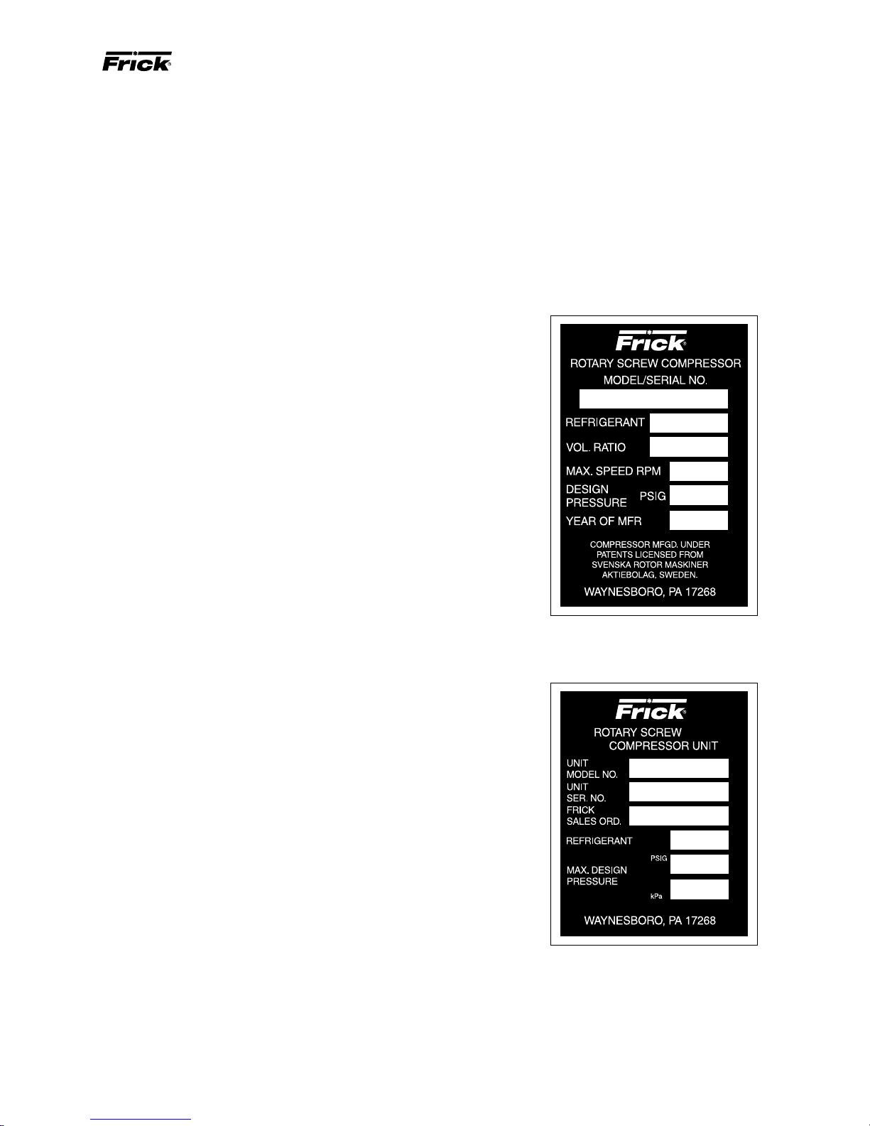
COMPRESSOR and UNIT IDENTIFICATION
Each compressor unit has 2 identification data plates. The
compressor data plate, containing compressor model and
serial number, is mounted on the compressor body . The unit
data plate, containing unit model, serial number, and Frick
sales order number, is mounted on the side of the motor
base.
NOTE: When inquiring about the compressor or unit, or
ordering repair parts, pro vide the MODEL, SERIAL, and
FRICK SALES ORDER NUMBERS from these data plates.
It is recommended that the entering vapor temperature to
the compressor be superheated to 10
ant saturation temperature. This ensures that all refrigerant
at the compressor suction is in the vapor state.
O
F above the refriger-
DESIGN LIMITATIONS
The compressor units are designed for operation within the
pressure and temperature limits as shown in Frick Pub.
E70-100 SED.
JOB INSPECTION
Immediately upon arrival examine all crates, boxes and exposed compressor and component surfaces for damage.
Unpack all items and check against shipping lists for any
possible shortage. Examine all items for damage in transit.
TRANSIT DAMAGE CLAIMS
All claims must be made by consignee. This is an ICC requirement. Request immediate inspection by the agent of
the carrier and be sure the proper claim forms are executed.
Report damage or shor tage claims immediately to Frick ,
Sales Administration Department, in Waynesboro, PA.
COMPRESSOR DATA PLATE
UNIT DATA PLATE
Page 4
Page 4
RXB PLUS ROTARY SCREW COMPRESSOR UNITSS70-101 IOM
INSTALLATION
FOUNDATION
Each RXB PLUS Rotary Screw Compressor Unit is shipped
mounted on a wood skid which must be removed prior to unit
installation. CA UTION: Allow space f or servicing both ends
of the unit. A minimum of 24 inches is recommended.
The first requirement of the compressor foundation is that it
must be able to support the weight of the compressor package including coolers, oil, and refrigerant charge. Screw
compressors are capable of converting large quantities of
shaft power into gas compression in a relatively small space
and a mass is required to effectively dampen these relatively high frequency vibrations.
Firmly anchoring the compressor package to a suitable foundation by proper application of grout and elimination of piping stress imposed on the compressor is the best insurance
for a trouble free installation. Use only the certified general
arrangement drawings from Frick to determine the mounting foot locations and to allow for recommended clearances
around the unit for ease of operation and servicing. Foundations must be in compliance with local building codes and
materials should be of industrial quality.
The floor should be a minimum of 6 inches of reinforced concrete and housekeeping pads are recommended. Anchor bolts
are required to firmly tie the unit to the floor. Once the unit is
rigged into place (See HANDLING and MOVING), the feet m ust
then be shimmed in order to level the unit. The shims should
be placed to position the feet roughly one inch above the housekeeping pad to allow room for grouting. An expansion-type
epoxy grout must be worked under all areas of the base with
no voids and be allowed to settle with a slight outw ard slope so
oil and water can run off of the base.
When installing on a steel base, the following guidelines should
be implemented to properly design the system base:
1. Use I-beams in the skid where the screw compressor will be
attached to the system base. They should run parallel to the
package feet and support the feet f or their full length.
2. The compressor unit f eet should be continuously welded to
the system base at all points of contact, or bolted.
3. The compressor unit should not be mounted on vibration
isolators in order to hold down package vibration le vels.
4. The customer’ s foundation f or the system base should fully
support the system base under all areas, but most certainly
under the I-beams that support the compressor package.
When installing on the upper floors of buildings, extra precautions should be taken to prevent normal package vibration from being transferred to the building structure. It may
be necessary to use rubber or spring isolators, or a combination of both, to prevent the transmission of compressor
vibration directly to the structure. Howe ver , this may increase
package vibration levels because the compressor is not in
contact with any damping mass. The mounting and support
of suction and discharge lines is also very important. Rubber or spring pipe supports may be required to avoid exciting the building structure at any pipe supports close to the
compressor package. It is best to emplo y a vibration expert
in the design of a proper mounting arrangement.
In any screw compressor installation, suction and discharge lines
should be supported in pipe hangers (preferably within 2 ft. of
vertical pipe run) so that the lines won’t move if disconnected
from the compressor. See table for Allowab le Flange Loads .
A licensed architect should be consulted to determine the
proper foundation requirements for any large engine or turbine drive.
ALLOWABLE FLANGE LOADS
NOZ.
SIZE
NPS
(in.)
1
1.25
1.5
2
3
4
5
6
8
10
12
14
MOMENTS (ft-lbf) LOAD (lbf)
AXIAL VERT. AXIAL VERT. LAT.LA T.
M
R
25
25
50
100
250
400
425
1000
1500
1500
1500
2000
M
175
200
400
750
1000
1200
1500
1800
25
25
40
70
M
C
25
25
40
70
175
200
400
750
1000
1200
1500
1800
PVCV
L
50
50
100
150
225
300
400
650
1500
1500
1500
1700
50
50
75
125
250
400
450
650
900
1200
1500
2000
L
50
50
75
125
250
400
450
650
900
1200
1500
2000
When applying screw compressors at high pressures, the
customer must be prepared for package vibration and noise
higher than the values predicted for normal refrigeration duty .
Proper foundations and proper installation methods are vital; and ev en then, sound attenuation or noise curtains may
be required to reduce noise to desired levels.
For more detailed information on Screw Compressor F oundations, please request Frick publication S70-210 IB.
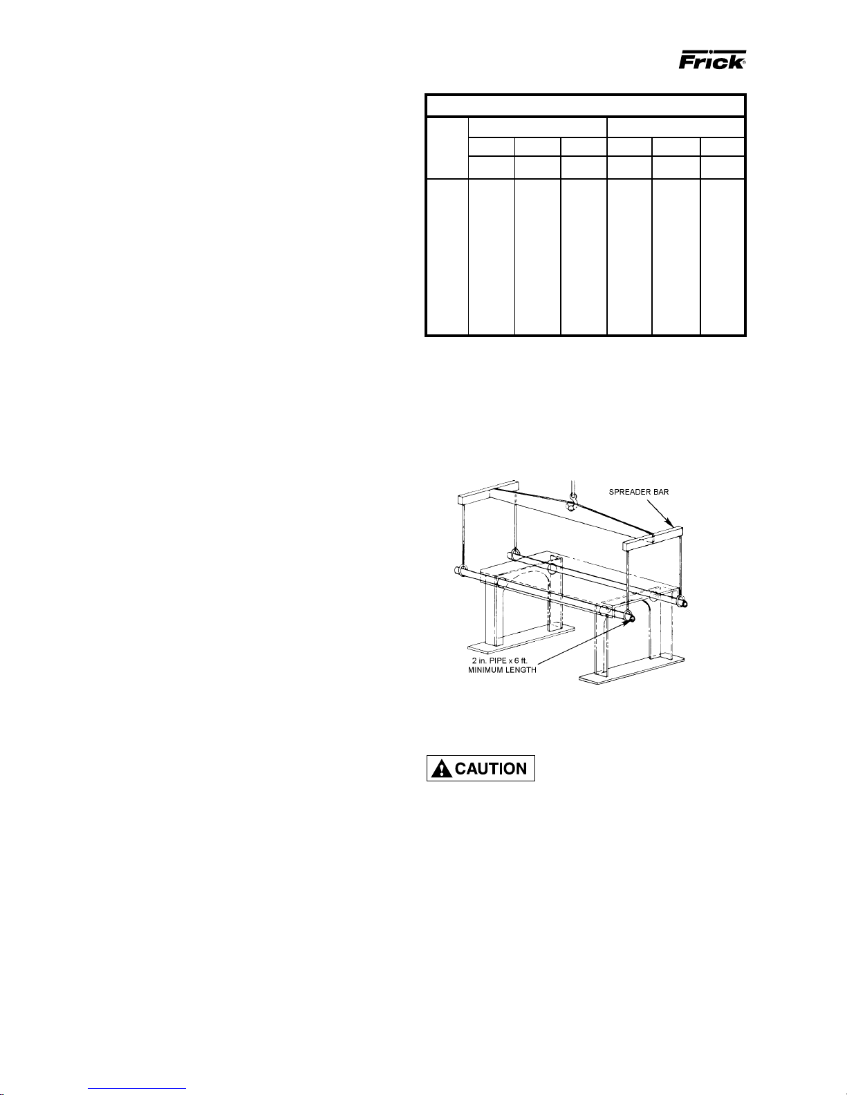
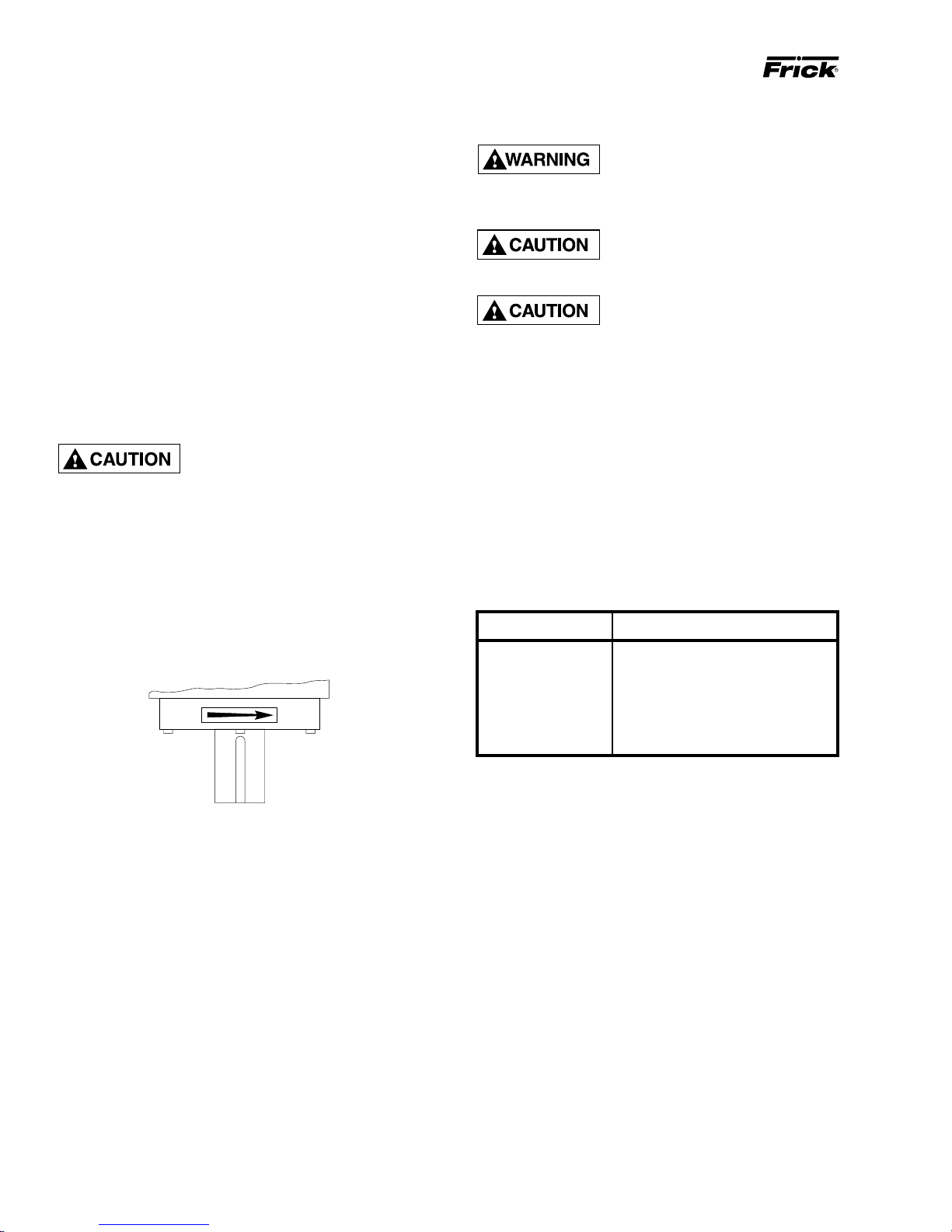
FIG. 1 - RECOMMENDED LIFTING METHOD
HANDLING AND MOVING
THIS UNIT MAY BE TOP HEAVY.
USE CARE WHILE HANDLING.
both the length and width of the package to prevent
bending of oil lines and damage to the package.
The unit can be moved with rigging, using a crane or forklift.
The recommended method is to insert lengths of 2" pipe
through the lifting holes in the vertical supports (see FIG. 1).
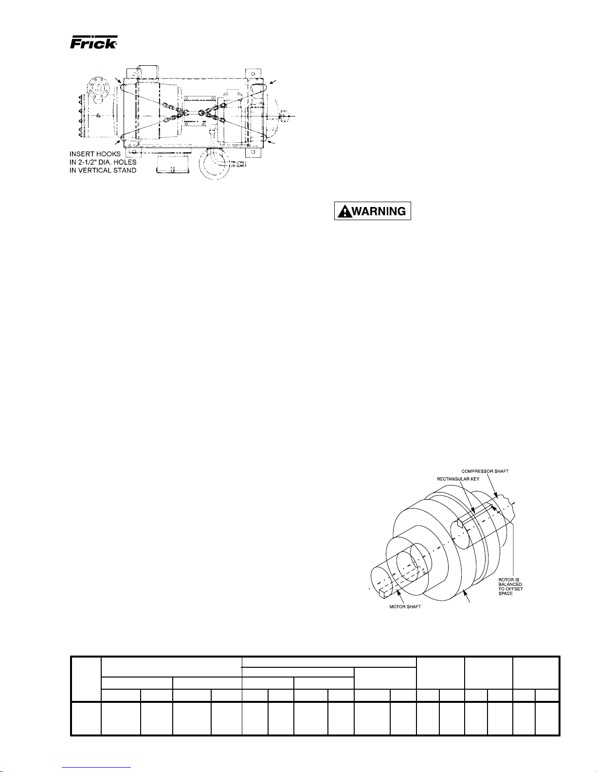
Alternatively, hooks may be used in rigging, inserting them
in the lifting holes (see FIG. 2).
Use CAUTION in locating the lifting ring. If no motor is
mounted, the lifting ring should be moved off center to the
compressor side of the unit because 60 percent of the weight
is toward the compressor end. If a motor is mounted, appropriate adjustment in the lifting point should be made to
compensate for motor weight. Adjustment of the lifting point
must also be made for any additions to the standard package, such as an external oil cooler, etc., as the center of
balance will be affected.
Spreader bars should be used on
Page 5
RXB PLUS ROTARY SCREW COMPRESSOR UNITS S70-101 IOM
INSTALLATION
FIG. 2 - ALTERNATIVE LIFTING METHOD
The unit can be moved with a forklift by forking under the
skid, or it can be skidded into place with pinch bars by pushing against the skid. NEVER MOVE THE UNIT BY PUSH-
ING OR FORKING AGAINST THE SEPARATOR SHELL
OR ITS MOUNTING SUPPORTS.
SKID REMOVAL
If the unit is rigged into place the skid can be removed by
taking off the nuts and bolts that are fastening the unit mounting supports to the skid before lowering the unit onto the
mounting surface.
If the unit is skidded into place, remove the cross members
from the skid and remove the nuts anchoring the unit to the
skid. Using a 5-ton jack under the separator, raise the unit at
the compressor end until it clears the two mounting bolts.
Spread the skid to clear the unit mounting support, then lower
the unit to the surface. Repeat procedure on opposite end.
MOTOR MOUNTING
The following procedure is required only when the motor is
mounted at the job site.
1. Thoroughly clean the motor feet and mounting pads of
grease, burrs, and other foreign matter to ensure firm seating of the motor.
Page 5
1. Inspect the shaft of the motor and compressor to ensure
that no nicks, grease, or foreign matter is present.
2. Inspect the bores in the coupling hubs to make sure that
they are free of burrs, dirt, and grit.
3. Check that the keys fit the hubs and shafts properly.
CH COUPLING – The T.B. Woods Elastomeric CH Coupling
is used in most applications. It consists of two drive hubs
and a loose, gear-type Hytrel Drive Spacer. The split hub is
clamped to the shaft by tightening the clamp screws. T orque
is transmitted from the motor through the elastomeric gear
which floats freely between the hubs. Install as follows:
IT IS MANDA T OR Y THA T THE COUPLING CENTER BE REMOVED
AND THE DIRECTION OF MOTOR
ROTATION BE CONFIRMED
BEFORE
RUNNING THE
COMPRESSOR. Proper rotation of the compressor shaft
is clockwise looking at the end of the compressor shaft.
FAILURE TO FOLLOW THIS STEP COULD RESULT IN
BACKWARD COMPRESSOR ROTATION WHICH CAN
CAUSE COMPRESSOR FAILURE OR EXPLOSION OF
THE SUCTION HOUSING.
1. Slide one hub onto each shaft as far as possible. It may
be necessary to use a screwdriver as a wedge in the slot to
open the bore before the hubs will slide onto the shafts.
2. Hold the elastomeric gear between the hubs and slide
both hubs onto the gear to fully engage the mating teeth.
Make sure that the keys on the compressor and motor halves
of the coupling are offset 180
O
(see FIG. 3). Center the gear
and hub assembly so there is equal engagement on both
shafts. Adjust the space between hubs as specified in the
CH Coupling Data Table below.
3. Torque the clamping bolts in both hubs to the torque value
given in the CH Data Table. DO NOT USE ANY LUBRI-
CANT ON THESE BOLTS.
4. Proceed to Coupling Alignment.
2. Attach the motor to the base using the bolts and motorraising blocks, if required. Bolt snugly through the base.
3. Weld the four kick bolts into place so that they are positioned to allow movement of the motor feet.
4. Now that the motor has been set, check that the shafts
are properly spaced for the coupling being used. Refer to
the coupling data table for the applicable dimension.
COMPRESSOR/MOTOR COUPLING
INSTALLATION
RXB PLUS units are arranged for direct motor drive and
require a flexible drive coupling to connect the compressor
to the motor. Before installing, perform the following:
FIG. 3 - COUPLING/SHAFT KEYS INSTALLATION
CH COUPLING DATA TABLE
19.0
25.4
25.4
31.8
COUPLING HUB
15/16
1-3/8
1-13/16
2-3/8
23.8
34.9
46.0
60.3
FACE SPACING
7/8
1-1/16
1-1/8
1-7/16
CH
COUP-
LING
SIZE in. mm mm mmin. in. mm in. in. mm in. mm ft-lb Nm ft-lb Nm
6
7
8
9C
BETWEEN SHAFT SPACING
MIN *
3
3
3-13/16
3-9/16
76.2
76.2
96.8
90.5
3-1/4
3-7/16
4
5-7/16
MAX
101.6
138.1
161.9
149.2
SHAFT ENGAGEMENT
MIN MAX
3/4
1
1
1-1/4
22.2
27.0
28.6
36.5
MAXIMUM
INDICATOR
.004
.004
.004
.004
TOTAL
READING
.104
.104
.104
.104
DRIVE COUPLING
CLAMP
BOLT
TORQUE
10
20
35
35
13.6
27.1
47.5
47.5
KEYWAY
SETSCREW
TORQUE
13
13
13
13
17.6
17.6
17.6
17.6
Page 6
RXB PLUS ROTARY SCREW COMPRESSOR UNITSS70-101 IOM
Page 6
INSTALLATION
COUPLING ALIGNMENT PROCEDURE
The life of the compressor shaft seal and bearings, as well
as the life of the motor bearings, is dependent upon proper
coupling alignment. Couplings may be aligned at the factory but realignment MUST ALWAYS be done on the job
site after the unit is securely mounted on its foundation. Initial alignment must be made prior to start-up and rechecked
after a few hours of operation. Final (HOT) field alignment
can only be made when the unit is at operating temperature. After final (HOT) alignment has been made and found
to be satisfactory for approximately one week, the motor
may be dowelled to maintain alignment.
NOTE: Frick recommends cold aligning the motor .005"
high. This cold misalignment compensates for thermal
growth when the unit is at operating temperature.
Use dial indicators to measure the angular and parallel shaft
misalignment. Coupling alignment is attained by alternately
measuring angular and parallel misalignment and repositioning the motor until the misalignment is within specified
tolerances. The following procedure is recommended.
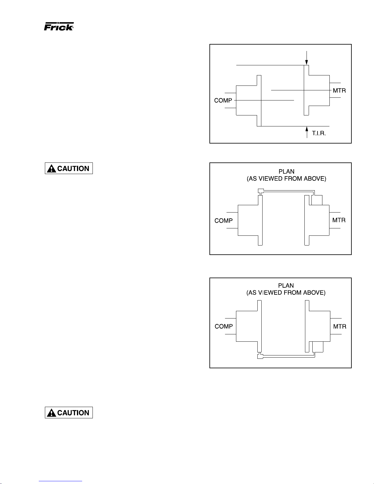
MISALIGNMENT MUST NOT EXCEED .004" FOR ALL CH COUPLINGS.
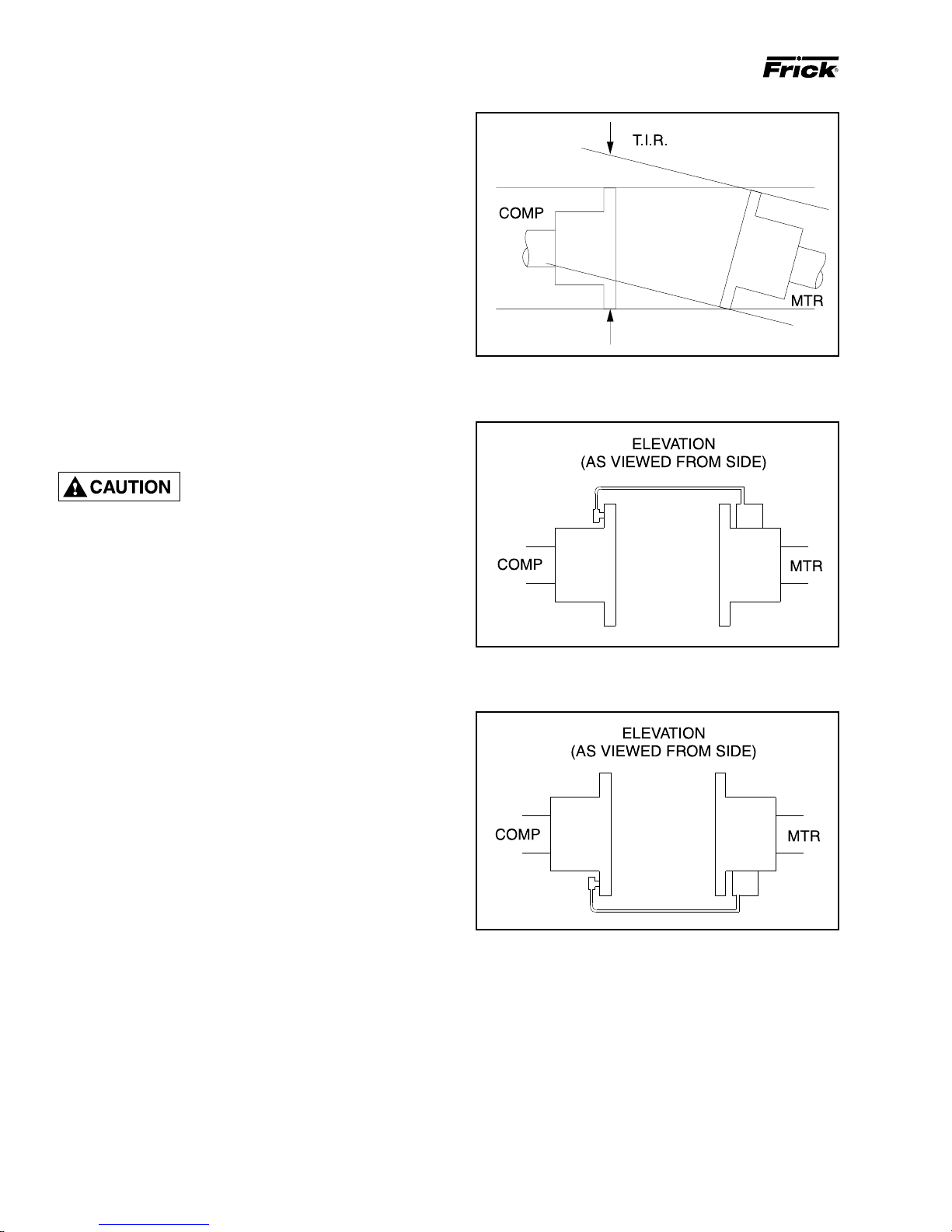
FIG. 1 - ANGULAR MISALIGNMENT
ANGULAR ALIGNMENT
1. To check angular alignment, as shown in Fig. 1., attach
dial indicator rigidly to the motor hub. Move indicator stem
so it is in contact with the outside face of compressor hub,
as shown in Fig. 2.
2. Rotate both coupling hubs several revolutions until they
seek their normal axial positions.
Check the dial indicator to be sure that the indicator stem is
slightly loaded so as to allow movement in both directions.
3. Set the dial indicator at zero when viewed at the 12 o’clock
position, as shown in Fig. 2.
O
4. Rotate both coupling hubs together 180
tion), as shown in Fig. 3. At this position the dial indicator
will show TOTAL angular misalignment.
NOTE: The use of a mirror is helpful in reading the indicator dial as coupling hubs are rotated.
5. Loosen motor anchor bolts and move or shim motor to
correct the angular misalignment.
After adjustments have been made for angular misalignment
retighten anchor bolts to prevent inaccurate readings. Repeat Steps 3 through 5 to check corrections. Further adjustments and checks shall be made for angular misalignment
until the total indicator reading is within the specified tolerance.
(6 o’clock posi-
FIG. 2 - DIAL INDICATOR ATTACHED (AT 12 O'CLOCK)
FIG. 3 - DIAL INDICATOR AT 6 O'CLOCK
Page 7
RXB PLUS ROTARY SCREW COMPRESSOR UNITS S70-101 IOM
INSTALLATION
P ARALLEL ALIGNMENT
6. To check parallel alignment, as shown in Fig. 4, reposi-
tion dial indicator so the stem is in contact with the rim of the
compressor hub, as shown in Fig. 5.
Check the dial indicator to be sure that the indicator stem is
slightly loaded so as to allow movement in both directions.
7. Check parallel height misalignment by setting dial indicator at zero when viewed at the 12 o'clock position. Rotate
both coupling hubs together 180
position the dial indicator will show TWICE the amount of
parallel height misalignment.
8. Loosen motor anchor bolts and add or remove shims under
the four motor feet until parallel height misalignment is within
specified tolerance when anchor bolts are retightened.
CARE MUST BE USED WHEN
CORRECTING FOR PARALLEL
MISALIGNMENT TO ENSURE
THAT THE AXIAL SPACING AND ANGULAR MISALIGNMENT IS NOT SIGNIFICANTLY DISTURBED.
9. After the parallel height misalignment is within tolerance,
repeat Steps 1 through 5 until angular misalignment is within
specified tolerance.
O
(6 o'clock position). At this
Page 7
FIG. 4 - PARALLEL MISALIGNMENT
10. Check parallel lateral misalignment by positioning dial
indicator so the stem is in contact with the rim of the compressor hub at 3 o'clock, as shown in Fig. 6.
Set indicator at zero and rotate both coupling hubs together
O
(9 o'clock position), as shown in Fig. 5.
180
Adjust parallel lateral misalignment using the motor adjust-
ing screws until reading is within specified tolerance.
11. Recheck angular misalignment and realign if necessary .
12. Tighten motor anchor bolts and rotate both coupling hubs
together, checking the angular and parallel misalignment
through the full 360
O
travel at 90O increments. If dial read-
ings are in excess of specified tolerance, realign as required.
13. When the coupling hubs have been aligned to within
specified tolerance, a recording of the cold alignment must
be made for unit records and usage during hot alignment.
14. Bump the motor to check for correct compressor rotation. COMPRESSOR ROTATION IS CLOCKWISE WHEN
FACING COMPRESSOR SHAFT (see "CHECKING MOTOR/COMPRESSOR ROTATION", page 8). After verifica-
tion, install gear or disk drive spacer, as applicable.
15. Install the coupling guard before operating the compressor.
FIG. 5 - DIAL INDICATOR ATTACHED (AT 9 O'CLOCK)
FIG. 6 - DIAL INDICATOR AT 3 O'CLOCK
When installing drive spacer, make
sure that hub spacing is within lim-
its shown on the Coupling Data
T able applicable to the coupling being installed and that
the clamping bolt(s) are properly torqued.
Page 8
Page 8
RXB PLUS ROTARY SCREW COMPRESSOR UNITSS70-101 IOM
INSTALLATION
HOT ALIGNMENT OF COMPRESSOR/MOTOR
Hot alignments can only be made after the unit has operated for several hours and all components are at operating
temperatures.
Shut down the unit and quickly affix dial indicator to coupling motor hub, then take readings of both the face and rim
of the compressor hub. If these readings are within tolerance, record reading, attach coupling guard, and restart unit.
However, if the reading is not within limits, compare the hot
reading with the cold alignment and adjust for this difference; i.e. if the rim at 0
the motor rises .005" between its hot and cold state, .005"
of shims should be removed from under the motor.
After the initial hot alignment adjustment is made, restart
unit and bring to operating temperature. Shut down and recheck hot alignment. Repeat procedure unit hot alignment
is within specified tolerance.
O
and 180O readings indicates that
INSTALL COUPLING GUARD BEFORE OPERATING COMPRESSOR.
CHECKING MOTOR/COMPRESSOR
ROTATION
COMPRESSOR ROTATION IS CLOCKWISE WHEN FACING THE END OF THE COMPRESSOR SHAFT. Under NO
conditions should the motor rotation be checked with the
coupling center installed as damage to the compressor may
result.
COMPRESSOR
COMPRESSOR UNIT OIL
DO NOT MIX OILS of different
brands, manufacturers, or types.
Mixing of oils may cause excessive
oil foaming, nuisance oil le vel cutouts, oil pressure loss,
gas or oil leakage and catastrophic compressor failure.
Use of oils other than Frick Oil must
be approved in writing by Fric k engineering or warranty claim may be
denied.
Use of filter elements other than
Frick must be approved in writing
by Frick engineering or warranty
claim may be denied.
The oil charge shipped with the unit is the best suited lubricant for the conditions specified at the time of purchase. If
there is any doubt due to the refrigerant, operating pressures, or temperatures; refer to Frick Pub. E160-802 SPC
for guidance.
OIL CHARGE
The normal charging level is midway in the top sight glass
located midway along the oil separator shell. Normal operating level is between the top sight glass and bottom sight
glass. The following table gives the approximate oil charge
quantity.
TABLE - BASIC OIL CHARGE (Gal)
MODEL BASIC CHARGE* (GAL.)
12 10
15 10
19 14
24 14
30 17
39 17
50 21
HOLDING CHARGE AND STORAGE
Each compressor unit is pressure and leak tested at the
Frick factory and then thoroughly evacuated and charged
with dry nitrogen to ensure the integrity of the unit during
shipping and short term storage prior to installation.
NOTE: Care must be taken when entering the unit to
ensure that the nitrogen charge is safely released.
All units must be kept in a clean, dry location to prevent
corrosion damage. Reasonable consideration must be given
to proper care for the solid state components of the microprocessor. Unit which will be stored for more than two
months must have the nitrogen charge checked periodically.
* Add oil volume for external oil cooler, according to cooler
size selected: 6 x 5 TSOC - 4 gal.; 6 x 5 WCOC - 5 gal.; 8 x
5 TSOC - 6-1/2 gal.; and 8 x 5 WCOC - 8 gal.
Add oil by attaching the end of a suitable pressure type
hose to the oil charging valve, located on the top of the oil
separator on the compressor end of the separator. Using a
pressure-type pump and the recommended Frick oil, open
the charging valve and pump oil into the separator.
Oil distillers and similar equipment which act to trap oil must
be filled prior to unit operation to normal design outlet levels. The same pump used to charge the unit may be used
for filling these auxiliary oil reservoirs.
NOTE: The sight glass, located near the bottom of the
separator shell at the discharge end, should remain
empty when the unit is in operation. The presence of oil
in this end of the vessel during operation indicates liquid carryover or malfunction of the oil return.
OIL HEATER
Standard units are equipped with a 500 watt oil heater, providing sufficient heat to maintain the oil temperature for most
indoor applications during shutdown cycles to permit safe
Page 9
RXB PLUS ROTARY SCREW COMPRESSOR UNITS S70-101 IOM
INSTALLATION
Page 9
start-up. Should additional heating capacity be required
because of unusual environmental condition, contact Frick
Company. The heater is energized only when the unit is not
in operation.
DO NOT ENERGIZE THE HEATER
WHEN THERE IS NO OIL IN THE
UNIT, OTHERWISE THE HEATER
WILL BURN OUT. THE OIL HEA TER WILL BE ENERGIZED
WHENEVER 120 VOLT CONTROL POWER IS APPLIED
TO THE UNIT AND THE COMPRESSOR IS NOT RUNNING
UNLESS THE 10 AMP FUSE (1FU) IN THE CONTROL
PANEL IS REMOVED.
LIQUID INJECTION OIL COOLING
The liquid injection system provided on the unit is self-contained but requires the connection of the liquid line sized as
shown in the table and careful insertion of the expansion
valve bulb into the thermowell provided in the separ ator. High
pressure gas is connected through the regulator to the external por t on the liquid injection valve to control oil temperature. Refer to the liquid injection piping diagram.
NOTE: For booster applications, the high pressure gas
connection must be taken from a high side sour ce (highstage compressor discharge). This should be a minim um
3/8" line connected into the solenoid valve provided. This
gas is required by the expansion valve external port to
control oil temperature.
Where low compression ratios (low condensing pressures)
are anticipated, thermosyphon or water-cooled oil cooling
should be used. It is IMPERATIVE that an uninterrupted
supply of high pressure liquid refrigerant be provided to the
injection system at all times. Two items of EXTREME IM-
PORTANCE are the design of the receiver/liquid injection
supply and the size of the liquid line. It is recommended that
the receiver be oversized sufficiently to retain a 5 minute
supply of refrigerant for oil cooling. The evaporator supply
must be secondary to this consideration. Two methods of
accomplishing this are shown.
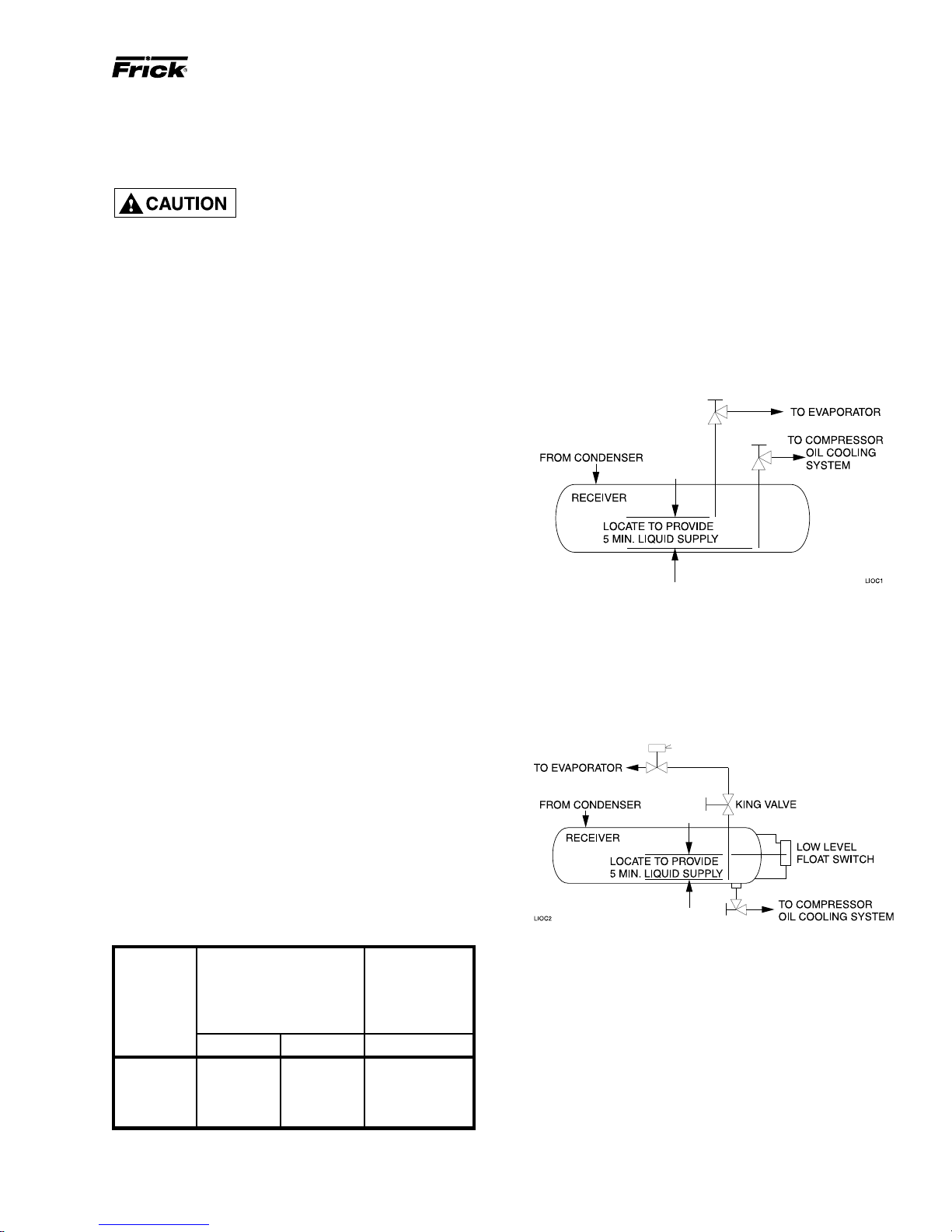
DUAL DIP TUBE METHOD
The dual dip tube method uses two dip tubes in the receiver. The liquid injection tube is below the evaporator tube to
ensure continued oil cooling when the receiver level is low.
High-stage compressor units may be supplied with singleport (low Vi) or dual-port (low Vi and high Vi), liquid injection
oil cooling. Single port will be furnished for low compression
ratio operation and dual port for high compression ratio operation. Booster compressor units use single-port, liquid injection oil cooling due to the typically lower compression
ratios.
The control system on high-stage units with dual-port, liquid
injection oil cooling switches the liquid refrigerant supply to
the high port when the compressor is operating at higher
compression ratios (3.5 Vi and above) for best efficiency.
The following table giv es the condensing temperature(s) with
the corresponding maximum evaporator temperature limit
for liquid injection usage and the minimum evaporator temperature for a single-port application.
TABLE - EVAPORATOR TEMPERATURE with
SINGLE-PORT LIQUID INJECTION
MAXIMUM MINIMUM *
EVAPORATOR EV AP TEMP
CONDENS- TEMPERATURE FOR FOR
ING LIQUID INJECTION SINGLE PORT
TEMP USAGE (LOW V i)
R-717 R-22 R-717 & R-22
75OF +10OF+5
85OF +25OF +15OF -17OF
95OF +35OF +25OF -11OF
105OF +40OF +35OF- 4
O
F -23OF
O
F
LEVEL CONTROL METHOD
The level control method utilizes a float level control on the
receiver to close a solenoid valve feeding the evaporator
when the liquid falls below that amount necessary for 5 minutes of liquid injection oil cooling.
* Dual Injection Kit will be shipped by Frick
below these temperatures.
Page 10
Page 10
RXB PLUS ROTARY SCREW COMPRESSOR UNITSS70-101 IOM
INSTALLATION
Liquid line sizes and the additional receiver volume (quantity of refrigerant required for 5 minutes of liquid injection oil
cooling) are given in the following table:
REF RXB RATE VOLUME
HIGH 19 1/2 – 15 .4
STAGE 24 1/2 – 20 .6
R-717 30 1/2 – 25 .7
HIGH 19 3/4 5/8 45 .6
STAGE 24 3/4 7/8 60 .8
R-22 30 3/4 7/8 75 1.0
BOOST- 19 1/2 – 3.5 .1
R-717 30 1/2 – 5.5 .2
BOOST- 19 3/4 1/2 9 .1
R-22 30 3/4 1/2 14.5 .2
MODEL PIPE TUBING (lb.) CU.FT.
12 1/2 – 10 .3
15 1/2 – 12.5 .4
39 1/2 – 30 8
50 3/4 – 40 1.1
12 3/4 5/8 30 .4
15 3/4 5/8 37.5 .5
39 3/4 7/8 95 1.3
50 1 1 125 1.7
12 1/2 – 2.1
15 1/2 – 2.5 .1
ER 24 1/2 – 4.5 .1
39 1/2 – 6.5 .2
50 1/2 –- 8.5 .3
12 3/4 1/2 6 .1
15 3/4 1/2 7 .1
ER 24 3/4 1/2 12 .2
39 3/4 1/2 18 .3
50 3/4 5/8 24 .3
LIQ. LINE SIZE* FLOW LIQUID
SCH 80 OD 5 MIN
* 100 ft. liquid line. For longer runs, increase line size ac-
cordingly.
NOTE: The water regulating valve shipped with the unit
will be sized to the specific flow for the unit.
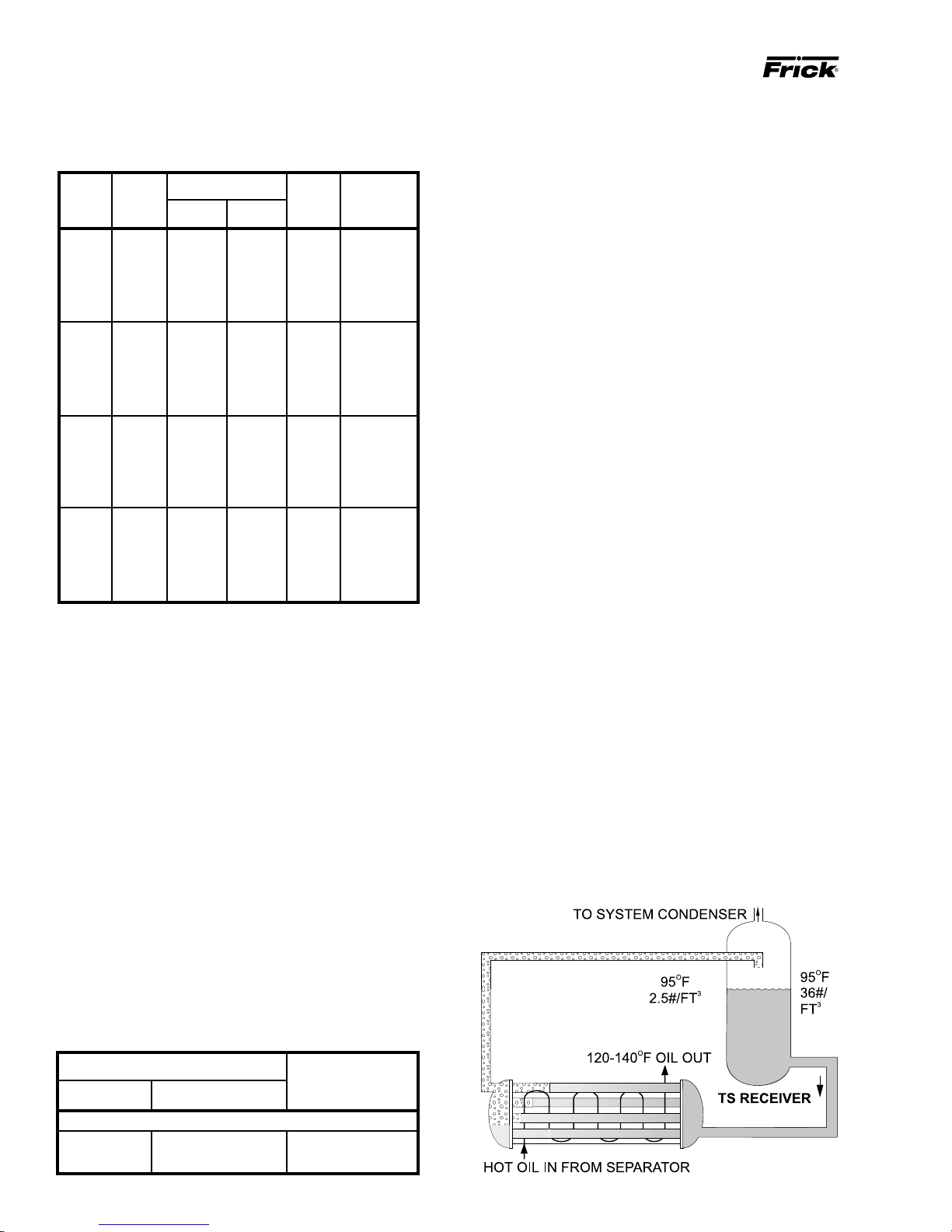
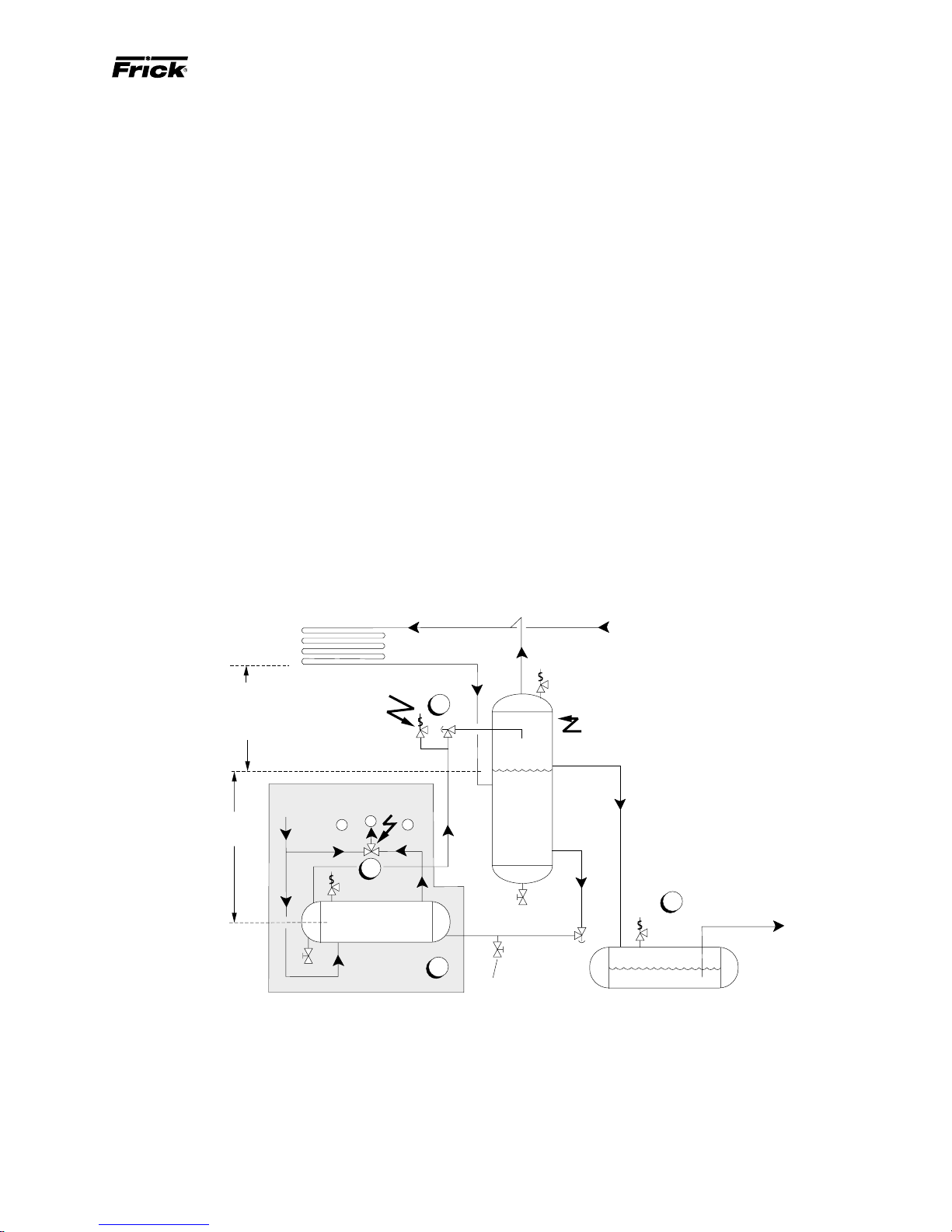
THERMOSYPHON OIL COOLING (OPTIONAL)
Thermosyphon oil cooling is an economical, effective method
for cooling oil on screw compressor units. Thermosyphon
cooling utilizes liquid refrigerant at condenser pressure and
temperature which is partially vaporized at the condenser
temperature in a shell and tube- or plate-type vessel cooling the oil to within 15
condensing pressure, is vented to the condenser inlet and
reliquified. This method is the most cost effective of all currently applied cooling systems since no compressor capacity is lost or compressor power penalties incurred. The vapor from the cooler need only be condensed, not compressed. Refrigerant flow to the cooler is automatic, driven
by the thermosyphon principle, and cooling flow increases
as the oil inlet temperature rises.
EQUIPMENT - The basic equipment required for a thermosyphon system consists of:
1. A source of liquid refrigerant at condensing pressure and
temperature located in close proximity to the unit to minimize piping pressure drop. The liquid le vel in the refrigerant
source must be 6 to 8 feet above the center of the oil cooler .
2. A shell and tube- or plate-type oil cooler with a 300 psi
minimum design working pressure on both the oil and refrigerant sides.
Due to the many variations in refrigeration system design
and physical layout, several systems for ensuring the above
criteria are possible.
O
F of that temperature. The vapor, at
WATER-COOLED OIL COOLING (OPTIONAL)
The shell and tube-type, water-cooled oil cooler is mounted
on the unit complete with all oil piping. The customer must
supply adequate water connections and install the two-way
water regulating valve. It is recommended that (local codes
permitting) the water regulator be installed on the water outlet
connection. Insert the water regulator valve bulb and well in
the chamber provided on the oil outlet connection. Determine the size of the water-cooled oil cooler supplied with
the unit, then refer to table for the water connection size
and water flow range (GPM). The water supply must be
sufficient to meet the required flow.
It is imperative that the condition of cooling water and closed
loop fluids be analyzed and maintained regularly and as
necessary to prevent corrosion of heat exchanger surfaces.
The oxygen content of river water and some other cooling
water sources will oxidize steel tubes and cause premature
failure. Careful attention to water treatment is essential to
ensure adequate life of steel cooler tubes if cooling tower
water is used. The condition of heat e xchanger tubes should
be checked semiannually to prevent hazard.
OIL COOLER DATA TABLE
SIZE - Inches APPROX
WATER FLOW
COOLER WATER CONN RANGE (GPM)
5 Foot Lengths
6" DIA. 1 NPT 10 – 23
8" DIA. 1-1/4 NPT 35 – 60
SYSTEM OPERATION - Liquid refrigerant fills the cooler
tube side up to the Thermosyphon receiver liquid level.
Water or hot oil (above the liquid temperature) flowing
through the cooler will cause some of the refrigerant to boil
and vaporize in the tubes. The vapor rises in the return line.
The density of the refrigerant liquid/vapor mixture in the return line is considerably less than the density of the liquid in
the supply line. This imbalance provides a differential pressure that sustains a flow condition to the oil cooler. This relationship involves:
1. Liquid height above the cooler.
2. Oil heat of rejection.
3. Cooler size and piping pressure drops.
Page 11
RXB PLUS ROTARY SCREW COMPRESSOR UNITS S70-101 IOM
INSTALLATION
Page 11
Current thermosyphon systems are using two-pass oil coolers and flow rates based on 4:1 overfeed.
The liquid/vapor returned from the cooler is separated in the
receiver. The vapor is vented to the condenser inlet and need
only be reliquified since it is still at condenser pressure.
INSTALLATION - The shell and tube-type thermosyphon oil
cooler with oil-side piping and a thermostatically controlled
mixing valve (if ordered) are factory mounted and piped. The
customer must supply and install all piping and equipment
located outside of the shaded area on the piping diagram
with consideration given to the following:
1. The refrigerant source, thermosyphon or system receiver, should be in close pro ximity to the unit to minimize piping
pressure drop.
2. The liquid level in the refrigerant source must be 6 to 8
feet above the center of the oil cooler.
3. A safety valve should be installed if refrigerant isolation
valves are used for the oil cooler.
4. F rick recommends the installation of an angle v alve in the
piping before the thermosyphon oil cooler to balance the
thermosyphon system. Frick also recommends the installation of sight glasses at the TSOC inlet and outlet to aid in
troubleshooting. The factory-mounted, plate-type thermosyphon oil cooler requires a refrigerant-side drain valve
to be provided and installed by the customer.
TSOC AND WCOC OPTIONAL OIL SIDE SAFETY RELIEF
- Compressor units, which have valves in the oil piping to
isolate the oil cooler from the oil separator for servicing,
may have factory installed piping to relieve the shell side
(oil side) safety valve directly into the oil separ ator, as sho wn
in the P & I diagrams on pages 58 through 60.
This arrangement uses a special UV stamped safety valve
rated for liquid and vapor relief . The safety v alve is designed
for 500 psi DWP and is set to relieve at 75 psi delta P. The
safety valve piping contains flanged connections should the
valve require maintenance or replacement.
Extra caution should be used when servicing an oil separator with this arrangement. If the oil cooler is valved off
from an oil separator which has been evacuated for servicing, then the oil cooler could relieve into the separator vessel if the 75 psi delta p setpoint is exceeded.
Other units, which do not use this special safety valve arrangement, will have factory mounted safety valves on the
shell side of the oil cooler which the installing contractor
should pipe into house safety systems designated suitable
for oil relief.
The component and piping arrangement shown below is intended only to illustrate the operating principles of thermosyphon oil cooling. Other component la youts ma y be better suited
to a specific installation. Ref er to publication E70-900E for additional information on Thermosyphon Oil Cooling.
CONDENSER
STATIC HEAD
TO O VERCOME
CONDENSER
PRESSURE DROP
8 Ft.
Min.
TSOCA
SYSTEM
SAFETY
VALVE
OIL TEMP
CONTROLVALVE
A
B
HOT
COOL
2
OIL OUT
THERMOSYPHON
OIL COOLER
HOT OIL IN
VAPOR
3
THERMOSYPHON
RECEIVER
LIQUID
LEVEL
C
1
Refrigerant-side drain valve
required for plate-type
thermosyphon oil coolers.
LIQUID OVERFLOW
DRAIN TO RECEIVER
TO SYSTEM
4
EVAPORATOR
SYSTEM
RECEIVER
(Mounted below Thermosyphon
receiver le vel)
1. The thermosyphon oil cooler is supplied with the oil side piped to the compressor unit and stub ends supplied on the refrigerant side.
2. A three-way oil temperature control valve is required where condensing temperature is expected to go below 65
3. A refrigerant-side saf ety valv e is required in this location only when refrigerant isolation valv es are installed between the cooler
and thermosyphon receiver. If no valves are used between the cooler and TSOC receiver, the safety v alv e on the TSOC receiver
must be sized to handle the volume of both vessels. Then, the safety valve on the cooler vent (liquid refrigerant side) can be
eliminated.
4. The system receiver must be below the thermosyphon receiver in this arrangement.
O
F.
Page 12
Page 12
RXB PLUS ROTARY SCREW COMPRESSOR UNITSS70-101 IOM
INSTALLATION
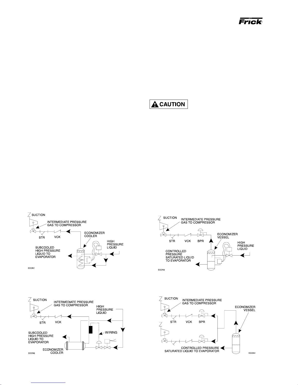
ECONOMIZER - HIGH STAGE (OPTIONAL)
The economizer option provides an increase in system capacity and efficiency by subcooling liquid from the condenser
through a heat exchanger or flash tank before it goes to the
evaporator. The subcooling is provided by flashing liquid in
the economizer cooler to an intermediate pressure level.The
intermediate pressure is provided by a port located part way
down the compression process on the screw compressor.
As the screw compressor unloads, the economizer port will
drop in pressure level, eventually being fully open to suction. Because of this, an output from the microprocessor is
generally used to turn off the supply of flashing liquid on a
shell and coil or DX economizer when the capacity falls below approximately 45%-60% capacity (85%-90% slide valve
position). This is done because the compressor will be more
efficient operating at a higher slide valve position with the
economizer turned off, than it will at a low slide valve position with the economizer turned on. Please note however
that shell and coil and DX economizers can be used at low
compressor capacities in cases where efficiency is not as
important as ensuring that the liquid supply is subcooled. In
such cases, the economizer liquid solenoid can be programmed to be left open whenever the compressor is running.
Due to the tendency of the port pressure to fall with decreasing compressor capacity, a back-pressure regulator
valve (BPR) is generally required on a flash economizer
system (FIG. 3) in order to maintain some preset pressure
difference between the subcooled liquid in the flash vessel
and the evaporators. If the back-pressure regulator valve is
not used on a flash economizer, it is possible that no pressure difference will exist to drive liquid from the flash v essel
to the evaporators, since the flash vessel will be at suction
pressure. In cases where wide swings in pressure are an-
ticipated in the flash economizer vessel, it may be necessary to add an outlet pressure regulator to the flash vessel
outlet to avoid overpressurizing the economizer port, which
could result in motor overload. Example: A system feeding
liquid to the flash vessel in batches.
The recommended economizer systems are shown below.
Notice that in all systems there should be a strainer (STR)
and a check valve (VCK) between the economizer vessel
and the economizer port on the compressor. The strainer
prevents dirt from passing into the compressor and the check
valve prevents oil from flowing from the compressor unit to
the economizer vessel during shutdown.
Other than the isolation valve
needed for strainer cleaning, it is
essential that the strainer be the
last device in the economizer line before the compressor. Also, piston-type check valves are recommended
for installation in the economizer line, as opposed to
disc-type check valves. The latter are more prone to gaspulsation-induced failure. The isolation and check valves and strainer should be located as closely as possible to the compressor, preferably within a few feet.
For refrigeration plants employing multiple compressors on
a common economizing vessel, regardless of economizer
type, each compressor must have a back-pressure regulating valve in order to balance the economizer load, or gas
flow, between compressors. The problem of balancing load
becomes most important when one or more compressors
run at partial load, exposing the economizer port to suction
pressure. In the case of a flash vessel, there is no need for
the redundancy of a back-pressure regulating valve on the
vessel and each of the multiple compressors. Omit the BPR
valve on the flash economizer vessel and use one on each
compressor, as shown in FIG. 4.
FIG. 1 - SHELL and COIL ECONOMIZER SYSTEM
FIG. 2 - DIRECT EXPANSION ECONOMIZER SYSTEM
FIG. 3- FLASH ECONOMIZER SYSTEM
FIG. 4 -MUL TIPLE COMPRESSOR ECONOMIZER SYSTEM
Page 13

RXB PLUS ROTARY SCREW COMPRESSOR UNITS S70-101 IOM
INSTALLATION
Page 13
ELECTRICAL
NOTE: Before proceeding with electrical installation, read
the instructions in the section “Proper Installation of
Electronic Equipment in an Industrial Environment”.
RXB PLUS units are supplied with a SBC (single-board computer) microprocessor control system. Care must be taken
that the controls are not exposed to physical damage during handling, storage, and installation. The microprocessor
enclosure cover must be kept tightly closed to prevent entry
of moisture and foreign matter.
Customer-control power connections are made at the BOTTOM of
the microprocessor enclosure.
Consult local ordinances before installation. Current
transformer wiring should be kept separate. Extreme
care should be taken that metal filings or other foreign
material is not left in the microprocessor enc losure. Use
seal-tight conduit fittings to prevent moisture entry into
the microprocessor enclosure. This is the ONL Y electrical enclosure that should be opened during installation
and it should be kept tightly closed whenever work is
not being performed in it.
1. The compressor motor starter of the specified HP and
voltage for the starting method specified (across-the-line,
autotransformer, wye-delta, or solid state).
NOTE: If starting methods other than across-the-line are
desired, a motor/compressor torque analysis must be
done to ensure that sufficient starting torque is available, particularly in booster applications. Contact FRICK
Company if assistance is required.
2. If specified, the starter package can be supplied as a
combination starter with circuit breaker disconnect. However, the motor overcurrent protection/disconnection device
can be supplied by others, usually as a part of an electrical
power distribution board.
3. A 2.0 KVA control power transformer (CPT), to supply
120 volt control power to the control system and separator
oil heaters, is included. If environmental conditions require
more than a 500 watt oil heater, an appropriately oversized
control transformer will be required.
4. One (1) normally open, compressor-motor-starter auxiliary contact and 1 normally open, oil-pump-motor-star ter
auxiliary contact (opt.) should be supplied and wired as
shown on the starter package wiring diagram. In addition,
the compressor and oil pump motor starter (opt.) coils and
the CPT secondaries should be wired as shown on starter
package wiring diagram.
NOTE: Customer ground required, see Micro Panel Assembly Wiring Diagram.
MOTOR STARTER PACKAGE
5. The compressor motor Current Transformer (CT) can be
installed on any one phase of the compressor leads. NOTE:
The CT must see all the current on any one phase; therefore in wye-delta applications, BOTH leads of any one
phase must pass through the CT.
6. Oil Pump Option: If the optional oil pump is specified, an
oil pump starter must be a component of the unit starter
package. The pump starter should be equipped with fuses
or, in the case where the compressor motor is a different
voltage from the oil pump motor, a circuit breaker disconnect suitable for separate power feed.
NOTE: Do not install a compressor HAND/OFF/AUTO
switch in the starter package as this would bypass the
compressor safety devices.
Motor starter and interlock wiring requirements are shown
in the wiring diagram, above. All the equipment shown is
supplied by the installer unless a starter package is purchased from Frick . Starter packages should consist of:
NOTE: When compressor motor voltage is different from
oil pump motor voltage, supply a cir cuit breaker disconnect for separate feed in lieu of fuses.
Page 14
Page 14
RXB PLUS ROTARY SCREW COMPRESSOR UNITSS70-101 IOM
INSTALLATION
CURRENT TRANSFORMER (CT) RATIOS
The CT ratio for various motor sizes (with a 5 amp secondary) is given in the following table:
VOLTAGE
HP 200 230 380 460 575 2300 4160
20 100:5 100:5 100:5 100:5 100:5 - 25 100:5 100:5 100:5 100:5 100:5 - 30 200:5 100:5 100:5 100:5 100:5 - 40 200:5 200:5 100:5 100:5 100:5 - 50 200:5 200:5 100:5 100:5 100:5 - 60 300:5 200:5 200:5 100:5 100:5 - -
75 300:5 300:5 200:5 200:5 100:5 - 100 400:5 300:5 200:5 200:5 200:5 - 125 500:5 400:5 300:5 200:5 200:5 - 150 500:5 500:5 300:5 300:5 200:5 - 200 800:5 600:5 400:5 300:5 300:5 100:5 50:5
250 800:5 800:5 500:5 400:5 300:5 100:5 50:5
MINIMUM BURDEN RATINGS
The following table gives the minimum CT burden ratings.
This is a function of the distance between the motor starting
package and the compressor unit.
BA TTER Y B A CKUP
The battery backup prevents data loss during power interruption. It will maintain the adjustable setpoints stored in
RAM (Random Access Memory) for up to 1 year after power
loss. Expected battery life is 10 years. A trickle charge maintains the battery backup at peak charge when control voltage is present.
To prevent power loss, the battery backup is shipped disabled. To enable the batter y backup, a jumper pin located
near the top of the microprocessor circuit board (see illustration page 52) must be moved from OFF (pins 1-2) to ON
(pins 2-3).
NOTE: It is not necessary to disconnect the battery
backup during extended downtime.
BURDEN MAXIMUM DISTANCE FROM
RA TING FRICK P ANEL
USING # USING # USING #
ANSI VA 14 AWG 12 AWG 10 AWG
B-0.1 2.5 15 ft 25 ft 40 ft
B-0.2 5 35 ft 55 ft 88 ft
B-0.5 12.5 93 ft 148 ft 236 ft
In addition to the starter package interlocks shown on the
starter package diagram, the following optional interlocks
are on the typical RXB PLUS Screw Compressor unit with
the SBC Microprocessor Control System wiring diagram:
1. Remote LOAD, UNLO AD, and RUN interlocks in case the
customer desires to operate the unit from a remote control
device.
2. Alarm Horn output.
3. Control solenoid valve for the economizer option.
For customer control options, consult FRICK Company.
NOTE: The microprocessor will not operate without
EPROM chips installed. When EPROM chips are not installed, the microprocessor display will typically indicate two dark lines across both the upper and lower display screens.
Page 15
RXB PLUS ROTARY SCREW COMPRESSOR UNITS S70-101 IOM
OPERATION and START-UP INSTRUCTIONS
GENERAL INFORMATION
OPERATION
Page 15
The Frick RXB PLUS Rotary Screw Compressor Unit is an
integrated system consisting of six major subsystems:
1. Microprocessor Control Panel
2. Compressor
3. Compressor Lubrication System
4. Compressor Oil Separation System
5. Compressor Hydraulic System
6. Compressor Oil Cooling System
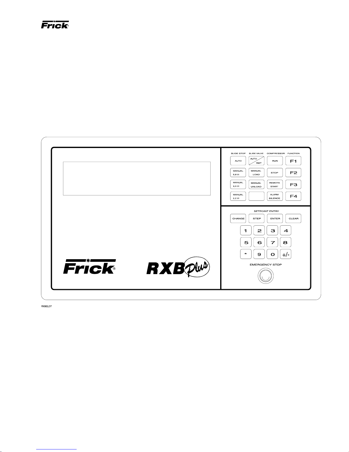
MICROPROCESSOR CONTROL PANEL
The information in this section of the manual provides the
logical step-by-step instructions to properly start up and operate the RXB PLUS Rotary Screw Compressor Unit.
THE FOLLOWING SUBSECTIONS MUST BE READ AND
UNDERSTOOD BEFORE ATTEMPTING TO START OR
OPERA TE THE UNIT.
The RXB PLUS compressor is controlled by a state-ofthe-art microprocessor control system. The microprocessor
continuously monitors the compressor unit’s condition and
operation. The microprocessor also directs instructions to
the various compressor unit subsystems.
The microprocessor has a membrane switch keyboard.
Pressing the keyboard in the area outlined as a key will cause
that function to be recognized by the microprocessor. The
keyboard has 32 membrane-type keys.
In addition to the keyboard, there is an emergency stop button. Pushing the emergency stop will bypass the computer
and remove all power from the outputs. This will shut down
the compressor motor and all high voltage to the compres-
sor auxiliary systems such as the oil pump and liquid injection solenoid. THE EMERGENCY STOP BUTTON IS FOR
EMERGENCY SHUTDOWN SITUATIONS ONLY and
MUST NOT BE USED TO ROUTINELY SHUT OFF THE
COMPRESSOR.
The microprocessor continuously monitors the state of the
battery which maintains setpoints and various other data. If
the battery voltage is low, the message “LOW BATT” will
flash in the lower right hand corner of the bottom display
(see page 14 for description of battery backup).
The microprocessor hardware contains an output watchdog circuit. If the microprocessor should fail, this circuit will
disable (turn off) all outputs.
Page 16

Page 16
RXB PLUS ROTARY SCREW COMPRESSOR UNITSS70-101 IOM
OPERATION
Revised 2/95
KEYS AND KEY FUNCTIONS
NOTE: The microprocessor will automatically return to
the main operating display after 60 seconds of keyboard nonactivity.
The [CHANGE] ke y rotates the dual display screen through
six display modes. The [CHANGE] key is also used to change
the status of various setpoints.
The [STEP] key steps or moves a set of flashing brackets
through the variable setpoints on the Adjustable setpoints
display, the Auto-cycle display, the Security display and the
Setback display. The setpoint enclosed within the flashing
brackets may be changed or updated. The [STEP] key is
also used when the Annunciator display is selected to step
through the annunciator’s four information displays.
NOTE: The [ * ] key is used to step or move the flashing
brackets, described above, backwards.
The [ENTER] key is used to enter new setpoint limits.
The [CLEAR] key will reset an alarm or cutout indication on
the annunciator screen and will clear the microprocessor to
allow continued operation or restarting if all conditions have
returned to normal and no other control lockouts are in force.
The [NUMERIC KEYPAD] is used to introduce new setpoint
limits.
The [+/-] key is used to toggle between pounds per square
inch gauge (g) and inches of mercury (hg).
1. Operating displays
2. Setpoints displays
3. Annunciator displays
4. Shutdown Record displays
5. Freeze displays
[F1] Operating display
[F2] Security display
[F3] Setback display
[F4] Auto Cycle display
NOTE: On initial powering of the microprocessor, and
any time power has been removed from the microprocessor, onl y the Operating, Setpoints, Ann unciator, and
Shutdown displays will display inf ormation. The Freeze
display will appear as a dark screen. The Freeze display
will only be present after a compressor unit cutout.
OPERATING DISPLAY *, Pages 1 and 2
OP.DISPLAY PAGE 1 Thu 03-01-89 15:33:36
Suction Disch Oil Compressor
14.3 hg 024 g 060 g Man Mode
O
F 135OF 135OF Running
-040
OP.DISPLAY PAGE 2 Thu 03-01-89 15:33:36
V Ratio S V Pos Pump %FLA Sep 132OF
2.2 070% on 096% HTR off
Auto Auto U
The [RUN], [STOP], and [REMOTE START] keys control
the starting and stopping of the compressor unit.
The [ALARM SILENCE] k ey will de-energize the alarm horn
output.
The [AUTO], [REMOTE], and [MANUAL] keys control the
operation of the compressor slide valve.
The [AUTO], [MANUAL 2.2], [MANUAL 3.5], and [MANUAL
5.0] keys control the operation of the compressor slide stop .
The [F1] function key will return the operator to the main
operating display. This function may be inv ok ed at any time,
even during setpoint entry.
The [F2] function ke y will call up the Security display. NOTE:
Press the [F2] key , as pr ompted b y the display, to return
to the previously selected display.
The [F3] function ke y will call up the Setback displa y . NOTE:
To exit the Setback display, press the [F1] key as
prompted by the display.
The [F4] function key will call up the Auto Cycle display.
NOTE: T o exit the A uto Cyc le display, press the [F1] key
as prompted by the display.
The microprocessor has two liquid crystal displays in an 8
line by 40 character format, for a total of 320 characters.
When power is first applied to the control panel, the unit will
be in the Operating display mode. To change to a different
display mode, press the [CHANGE] key. The display modes
in their order of rotation are:
OPERATING DISPLAY, P age 1
The Operating display is continuously updated and pro vides
a variety of information in regard to the current status of the
compressor’s condition and performance.
The information furnished by the Operating display is as follows:
The DAY, DATE, and TIME are displayed at the top right of
the display.
NOTE: To set day, date, and time, see TO CHANGE THE
ADJUSTABLE SETPOINTS.
SUCTION - Suction Pressure and Temperature are mea-
sured at the compressor inlet and are, respectively, displayed
in pounds per square inch gauge (g) or inches of mercury
(hg) and degrees Fahrenheit.
DISCH - Discharge Pressure and Temperature are measured at the compressor outlet and are, respectively, displayed
in pounds per square inch gauge (g) and degrees Fahrenheit.
OIL - Oil Pressure and Temperature are measured prior to
entering the compressor and are, respectively, displayed in
pounds per square inch gauge (g) and degrees Fahrenheit.
ALARM/CUTOUT - An Alarm or Cutout message indicates
an Alarm or Cutout setpoint has been reached, or exceeded.
Rotate the display mode to the Annunciator display for details. In the ev ent of a cutout, rotate to the F reez e displa y f or
further details.
*Display for illustrative purposes only.
COMPRESSOR - The compressor displa ys the status of the
compressor unit. The mode of operation will be indicated as
either manual (Man Mode) when the [RUN] key has been
Page 17
RXB PLUS ROTARY SCREW COMPRESSOR UNITS S70-101 IOM
OPERATION
pressed, automatic (AUTO MODE) when Auto Cycle has
been activated, remote (RMT MODE) when the [REMOTE]
key has been pressed, or off (OFF MODE).
RECYCLE DELAY - A Recycle Delay message indicates
that the compressor has started and has shut down within
the time delay setpoint period. The Recycle Delay will prevent the compressor from starting until the delay time expires and is intended to prevent damage to the compressor
motor from successive restarts. During Recycle Delay, the
microprocessor will alternatively flash “RECYCLE DELAY”
and the remaining delay time in minutes.
NOTE: Consult Motor Manufacturer for the recommended duration of the Recycle Delay.
Page 17
SETPOINTS PAGE 1B
Dead Band--[/./#]
Prop. Band--[/ / %]
Cycle Time--[/ / sec]
LOW % FLA---[/ / / %]
SETPOINTS PAGE 2 MLC Stop LD-[095%]
CT Factor-[078] MLC Force ULD[100%]
Aux1[Alarm] [NO] Hi Disch Cutout-[050 g ]
Aux2[Shutd] [NO] Hi Disch Alarm—[045 g ]
If the [RUN] key is pushed while
the unit is in Recycle Delay, the
compressor will start at the end of
the delay period.
OPERATING DISPLAY, P age 2
V RATIO - Volume Ratio is the ratio selected by the micro-
processor to provide the highest efficiency at any given suction and discharge pressure condition. Immediately below
this, an information space has been provided to indicate
whether V ratio is in the automatic (AUTO) or the manual
(MAN) mode.
SV POS - Slide valve position is display ed as a percentage.
This percentage reflects the mechanical position of the slide
valve and does not reflect the percentage of full load operation. Immediately below this information, space has been
provided to indicate whether SV Pos is in the automatic
(AUT O), manual (MAN), or remote (RMT) mode . The microprocessor will control this function in the automatic mode.
To the right of the mode indicator, two other messages may
appear:
L - Indicates Slide Valve loading.
U - Indicates Slide Valve unloading.
PUMP (Optional) - Pump displays the current status of the
oil pump. The display will read ON or OFF whenever the
HAND-OFF-AUT O switch is selected to A UT O and the compressor is running.
% FLA - Percent Full-Load Amps displays the percentage
of the drive motor, full-load amperage rating that the motor
is currently using.
SETPOINTS PAGE 3 HIGH STAGE RXB NP-22
Oil Heater----- [113F] Liq Inj Con-------[122F]
Hi Disch Cut -[212F] Hi Disch Alarm -[194F]
SETPOINTS PAGE 4
Hi Oil Temp Cutout --[167F] Alarm -- [158F]
Lo Oil Temp Cutout -- [49F] Alarm -- [58F]
Lo Oil Press. Cutout -- [005] Alarm -- [010]
The information furnished by these displays is as follows:
PB-[10% DB-[1.0 #]
SETPOINTS DISPLAY, Page 1A:
CAP CONTROL - The Capacity Control setpoint, reported
in pounds per square inch gauge (g) or inches of mercury
(hg), controls the loading and unloading of the compressor
when Capacity is in the automatic (AUTO) mode.
LO SUCT CUTOUT - The Low Suction Pressure Cutout,
reported in pounds per square inch gauge (g) or inches of
mercury (hg), will shut down the compressor if the suction
pressure drops to this limit or lower, f or 90 seconds or longer .
LO SUCT ALARM - The Low Suction Pressure Alarm, reported in pounds per square inch gauge (g) or inches of
mercury (hg), will trigger a prealarm if the suction pressure
drops to this limit or lower.
ID - The ID number is a prog rammable identification code
in telecommunications to access a specific compressor.
used
SEP - Separator displays the oil separator temperature in
degrees Fahrenheit.
HTR - Heater displays the condition of the oil separator
heater(s), indicating ON or OFF.
FORCED UNLD - A Forced Unload message indicates that
the percentage of motor, full-load amps has exceeded the
maximum limit and the microprocessor is unloading the compressor until the percentage FLA falls back to normal limits.
SETPOINTS DISPLAY *
SETPOINTS PAGE 1A ID=[33] [03-01-89]
Cap. Control-----[14.3 hg] Thu [15:33:36]
Lo Suct Cutout -[20.0 hg] Baud----[ 2400]
Lo Suct Alarm --[18.0 hg] Recy.Delay-[30]
*Display for illustrative purposes only.
DATE - The Date displays the current date in the following
format: Month - Day - Year.
DAY - Day will display the current day of the week.
TIME - The Time displays the current time in the following
format: Hours - Minutes - Seconds. The time is in 24:00:00
hour clock format.
BAUD - Shows the baud rate of the RS422 communication
port. Both ports are configured as follows: w ord = 8 bit, parity = none or even, stop = 1 bit. The communications port is
programmable from 300 to 19200 baud.
RECY. DELAY - The Recycle Delay displays the current
recycle delay setpoint in minutes. NOTE: Consult the mo-
tor manufacturer for recommended setpoint.
Page 18

Page 18
RXB PLUS ROTARY SCREW COMPRESSOR UNITSS70-101 IOM
OPERATION
SETPOINTS DISPLAY, P a ge 1B:
Dead Band - This is a + (plus) or - (minus) value above or
below the setpoint at which the compressor will neither load
nor unload. A dead band of 1 is the default value. It is adjustable between .5 lb to 5 lb in increments of .5. The [Step]
key is used to select this setpoint; then press the [Change]
key to toggle through the selections.
Proportional Band - This setpoint is used to determine the
amount of time the load/unload solenoid is energized, according to how far from the setpoint the actual control pressure is. The smaller the number, the longer a load/unload
signal will be sent; 10% is the default value. Selections are
2, 5, 10, 15, 20, or 25%. The [Step] k ey is used to select this
setpoint; then press the [Change] ke y to toggle through the
selections.
Cycle Time - Cycle time is the amount of time between the
beginning of each load/unload response. Ten seconds is
the default value. “Cycle Time” is adjustable between 5 and
30 seconds in 5 second intervals. The [Step] key is used to
select a setpoint; then press the [Change] key to toggle
through the selections.
Low % FLA - This setpoint is used to determine if the coupling has broken; 20% is the default value. It is adjustable
from 0 to 100% FLA. Use the [Step] ke y to select a setpoint;
then enter the desired setpoint and press the [Enter] key.
AUX 1 and A UX 2 - May be configured f or either an alarm or
shutdown and with either a normally closed (NC) or normally open (NO) contact.
TO CHANGE THE ADJUSTABLE SETPOINTS:
Adjustable Setpoints are stored in RAM (random access
memory) and are easily changed in the field.
Adjustable Setpoints are lost if
power is interrupted and the bat-
tery is not fully charged. To facilitate reentry, we suggest that a list of Adjustable
Setpoints be affixed to one end of the microprocessor
cabinet for reference.
NOTE: The following procedure also applies to the changing of the Security, Setback, and Auto Cycle display
setpoints.
1. Press the [CHANGE] key to rotate the display to the Ad-
justable Setpoints display.
2. Press the [STEP] key to move or step a set of flashing
brackets through the v arious setpoints. A setpoint is selected
for change or update when it is enclosed by the flashing
brackets.
NOTE: The DAY indicator, itself, will flash when selected
for change or update.
SETPOINTS DISPLAY, Page 2:
MLC STOP LD - The Motor Load Control Stop Load, re-
ported as a percentage of the motor, full-load amps (FLA),
will prevent the compressor capacity control pistons from
loading when the setpoint is equaled or exceeded. NOTE:
Consult motor manufacturer for recommended setpoint.
MLC FORCE ULD - The motor Load Control Force Unload,
reported as a percentage of the motor, full-load amps (FLA),
will force the compressor to unload until the motor, full-load
amps (FLA) fall within 1% of the setpoint or lower. NOTE:
Consult motor manufacturer for recommended setpoint.
HI DISCH CUTOUT - The High Discharge Pressure Cutout,
reported in pounds per square inch gauge (g), will shut down
the compressor if the discharge pressure equals or exceeds
this setpoint.
HI DISCH ALARM - The High Discharge Pressure Alarm,
reported in pounds per square inch gauge (g) will trigger a
prealarm if the discharge pressure equals or exceeds this
setpoint.
CT FACTOR - The Current Transformer Factor records the
proper current transformer factor to match the compressor
motor FLA rating to the current transformer primary rating.
The CTF factor is programmable and its correct value is
determined by the following formula:
CTF =
* See motor nameplate.
** See CT located in starter panel.
EXAMPLE: FLA = 230 Amps
CT = 300 (300:5)
CTF = = 78 (Round to whole number)
10x CT (Current Transformer Primary Amps **)
1024 x 230
10 x 300
1024 x FLA (Full Load Amps *)
3. Having selected the setpoint to be changed, the [NUMERIC KEYPAD] may be used to enter the new setpoint.
NOTE: All digits must be entered, including zeros. For
example, (01.0).
NOTE: The D A Y, AUX 1, and AUX 2 setpoints, once selected,
are changed or updated by pressing the [CHANGE] key.
NOTE: Certain setpoints may be reported in either pounds
per square inch gauge (g) or inches of mercury (hg). To
toggle between (g) and (hg), ha ving selected the setpoint,
press the [+/-] key to toggle between (g) and (hg).
4. In the event that an incorrect setpoint is keyed in com-
pletely or partially, press the [CLEAR] key to restore the
original setpoint. Pressing the [CLEAR] key a second time
will eliminate the flashing brackets.
5. Having keyed the desired setpoint, press the [ENTER]
key. The new setpoint will be entered and the flashing br ackets will move or step to the next setpoint.
NOTE: A setpoint entry outside the parameters of the
Adjustable Setpoint display will be refused and the original Adjustable setpoint will be restored.
NOTE: To clear any time values [STEP] to the desired
setpoint, press [CHANGE] and then press [CLEAR].
HOW T O DETERMINE
ADJUST ABLE SETPOINTS:
Adjustable Setpoints should reflect values compatible with
normal system operation. Too high a Low Suction Pressure
Alarm setpoint may cause nuisance prealarms. Similarly,
cutout setpoints should not fall within what are considered
normal plant operation. As a rule of thumb, set the Low Suction Pressure Alarm 5 PSIG lower than the lowest normal
suction pressure. The Low Suction Pressure Cutout should
be 5 to 10 PSIG lower than the Low Suction Pressure Alarm
setpoint.
Page 19

RXB PLUS ROTARY SCREW COMPRESSOR UNITS S70-101 IOM
The High Discharge Pressure Cutout should be set at 90%
of the setting of the lowest high side relief valve. The High
Discharge
the Cutout.
The Capacity Control setpoint should be the equivalent of
the normal suction condition.
Pressure Alarm should be set 10 PSIG lower than
OPERATION
FIXED SETPOINTS:
Fixed setpoints define the limits of acceptable compressor
operation. Fix ed Setpoints are factory determined, stored in
programmed memory (PROM), and will remain in memory if
power to the microprocessor is interrupted.
SETPOINTS DISPLAY, Page 3:
OIL HEA TER - The Oil Heater setpoint, reported in degrees
Fahrenheit, turns on the oil separator heater(s) when the oil
temperature equals or falls below this setpoint whenev er the
compressor is NOT running.
LIQ INJ CON - The Liquid Injection Control, reported in degrees Fahrenheit, will shut off the liquid refrigerant supply to
the compressor if the oil temperature equals or falls below
this setpoint.
HI DISCH CUT ported in degrees Fahrenheit, will shut down the compressor if
the discharge temperature equals or exceeds this setpoint.
HI DISCH ALARM - The High Discharge T emperature Alarm,
reported in degrees Fahrenheit, will trigger a prealarm if the
discharge temperature equals or exceeds this setpoint.
The High Discharge Temperature Cutout, re-
SETPOINTS DISPLAY, Fixed, Pa ge 4:
HI OIL TEMP CUTOUT - The High Oil Temperature Cutout,
reported in degrees Fahrenheit, will shut down the compressor if the oil temperature equals or exceeds this setpoint.
HI OIL TEMP ALARM - The High Oil Temperature Alarm,
reported in degrees Fahrenheit, will trigger a prealarm if the
oil temperature equals or exceeds this setpoint.
LOW OIL TEMP CUTOUT - The Low Oil T emperature Cutout,
reported in degrees Fahrenheit, will shut down the compressor if the oil temperature equals or falls below this setpoint.
LOW OIL TEMP ALARM - The Low Oil Temperature Alarm,
reported in degrees Fahrenheit, will trigger a prealarm if the
oil temperature equals or falls below this setpoint.
LO OIL PRESS CUTOUT - The Low Oil Cutout will shut
down the compressor when the oil pressure equals or falls
below this setpoint.
LO OIL PRESS ALARM - The Low Oil Alarm will trigger a
prealarm when the oil pressure equals or falls below this
setpoint.
When a prealarm or cutout occurs, a flashing ALARM or
CUTOUT indicator will appear in the lower right hand corner
of the Operating display. To determine the fault, rotate to the
Annunciator display by pressing the [CHANGE] key.
Page 19
Revised 8/97
ANNUNCIA T OR DISPLAY *
ANNUNCIATOR: PG-01 Thu 03-01-89 15:33:36
(Use STEP key to advance PAGE)
High Press. Cutout *********************
High Press. Alarm *********************
ANNUNCIATOR: PG-02 Thu 03-01-89 15:33:36
(Use STEP key to advance PAGE)
Low Press. Cutout *********************
Low Press. Alar m *********************
ANNUNCIATOR: PG-03 Thu 03-01-89 15:33:36
(Use STEP key to advance PAGE)
Oil Press. Cutout *********************
Oil Press. Alarm *********************
ANNUNCIATOR: PG-04 Thu 03-01-89 15:33:36
(Use STEP key to advance PAGE)
Hi Oil Temp Cutout *********************
Hi Oil Temp Alarm *********************
ANNUNCIATOR: PG-05 Thu 03-01-89 15:33:36
(Use STEP key to advance PAGE)
Low Oil Temp Cutout *********************
Low Oil Temp Alarm *********************
ANNUNCIATOR: PG-06 Thu 03-01-89 15:33:36
(Use STEP key to advance PAGE)
Disch. Temp Cutout *********************
Disch. Temp Alarm *********************
ANNUNCIATOR: PG-07 Thu 03-01-89 15:33:36
(Use STEP key to advance PAGE)
Comp. Auxiliary *********************
Pump Aux. Not Used *********************
ANNUNCIATOR: PG-08 Thu 03-01-89 15:33:36
(Use STEP key to advance PAGE)
Oil Level *********************
Comp. Differential *********************
ANNUNCIATOR: PG-09 Thu 03-01-89 15:33:36
(Use STEP key to advance PAGE)
Superheat Cutout *********************
Superheat Alarm *********************
ANNUNCIATOR: PG-10Thu 03-01-89 15:33:36
(Use STEP key to advance PAGE)
Aux. 1 (Alarm) *********************
Aux. 2 (Shutdown) *********************
The Annunciator display lists all ke y operative points on nine
sequential displays. These displa ys can be rotated from page
#1 thru page #9 by pressing the [STEP] key . When a prealarm
or cutout is triggered, the pertinent point will flash and the
time of the occurrence will be recorded to the right of the
alarm.
ANNUNCIATOR: PG-11 Thu 03-01-89 15:33:36
(Use STEP key to advance PAGE)
Low Motor Amps *********************
Sensor Fault *********************
*Displays for illustrative purposes only.
Page 20
Page 20
RXB PLUS ROTARY SCREW COMPRESSOR UNITSS70-101 IOM
OPERATION
Compressor Differential Cutout - The differential cutout
has been lowered from 55 lb to 25 lb. Cutout will occur after
five minutes. T o allow oper ation at low differential pressures ,
the micro will take the following steps:
A. Force unload the compressor to 50% and display an "F
Unload" when the oil pressure is within 10 lb of the main oil
injection port pressure and the slide valve position is greater
than 50%.
B. Prohibit the compressor from loading and display a "Ld
Inhib" message when the differential is within 15 lb of the
main oil injection port pressure.
Oil Pressure Alarm and cutout - Prelube and Cycling Oil
Pump version when pump is not running. Alarm will occur if
oil pressure is 25 lb below discharge pressure or within 10
lb of suction pressure for 30 seconds. Cutout occurs if oil
pressure is 30 lb below discharge pressure or if oil pressure
is within 7 lb of suction pressure for 10 seconds and alarm
has already been set.
Full Lube and Cycling Oil Pump version when oil pump is
running. Alarm occurs if oil pressure is within 10 lb of discharge pressure for 30 seconds. Cutout occurs when oil
pressure is within 5 lb of discharge pressure for 10 seconds
and oil pressure alarm has been set.
Cycling Oil Pump Control - The oil pump will cut off when
differential pressure between suction and discharge pressure is 55 lb or greater. Upon pump termination the above
cutout logic (pump not running) is utilized. Pump cut-in occurs when the differential pressure between suction and discharge is 45 lb or less. Oil pressure alarm and cutout logic
(pump running) begins after a 30 second delay which allows the oil pump to build pressure.
Prealarms are self-clearing. At this time the alarm will stop
flashing, but the time of the first occurrence will still be recorded to the right of the alarm. Pressing the [CLEAR] key
while at the Annunciator display will clear all alarms and/or
cutouts.
In order to restore the Annunciator display and resume normal operation it will be necessary to go through the following steps:
1. Correct the conditions causing the alarm.
2. Press the [ALARM SILENCE] key. (This action ma y pre-
cede correcting the conditions causing the alarm).
3. To clear or reset the Annunciator pages, press the
[CLEAR] key. This will also clear the ALARM or CUTOUT
indicator from the Operating display.
4. Press [F1] to call up the Operating display. If the conditions causing the alarm have not been corrected or a new
fault has occurred, a new ALARM or CUTOUT message
will appear.
NOTE: Use of the Emergency Stop Button may trip one
or more alarm setpoints.
SHUTDOWN RECORD DISPLAY *
SHUTDOWN RECORD P1 Thu 03-01-89 15:33:36
Hi Oil Temp Cutout *********************
Hi Oil Temp Cutout *********************
Low Temp Cutout *********************
SHUTDOWN RECORD P2 Thu 03-01-89 15:33:36
Low Temp Cutout *********************
Disch. Temp Cutout *********************
Disch. Temp Cutout *********************
The Shutdown Record display keeps a record of the last six
shutdowns (cutouts). This information will help troubleshoot
persistent operational problems. The most recent cutout will
appear on the top line of page 1 of the display with the oldest appearing on the last or bottom line of page 2. When a
cutout occurs, all information is moved down one line and
the new cutout appears at the top of page 1. When the display is full, the oldest record is dropped off the display and
is not retained in memory. The information presented is echoed from the Annunciator display, providing the type of cutout, the day, the date, and the time. NOTE: This informa-
tion will not be lost due to power failure.
FREEZE DISPLAY *
FREEZE DISPLAY P1 Thu 03-01-89 15:33:36
Suction Disch Oil CUTOUT Compressor
14.3 hg 120 g 060 g OFF Mode
-040 F 135 F 135 F
FREEZE DISPLAY P2 Thu 03-01-89 15:33:36
V Ratio SV Pos Pump %FLA Sep 132
2.2 000% off 000% HTR off
Auto Auto L
The Freeze displa y has the same appear ance and contains
the same information as the Operating display. (For a description of the information presented by the Freeze displa y,
refer to the Operating display.) The Freeze display freezes
the information of the Operating display A T THE MOMENT
OF A COMPRESSOR CUTOUT. The information on the
Freeze displa y can help the operator to identify the cause of
a fault which occurred when no one was present. The F reeze
display will retain the information generated by a cutout until
a new cutout occurs or power is removed from the microprocessor.
Do not confuse the Freeze display
with the Operating display. In or-
der to avoid confusion remember
that the displayed information on the Operating displa y
is constantly being updated and changed. The Freeze
display is fixed and FREEZE DISPLAY appears in the
upper left hand corner of the display.
NOTE: The Freeze display will appear as a blank screen
when power is initially furnished to the unit, and it will
return to a blank screen anytime power is removed fr om
the microprocessor.
O
F
SECURITY DISPLAY *
SECURITY DISPLAY Press F2 To Exit
Setpoints Access ---- [Enabled ] Keyboard
Enter Access Code -[*****]
*Display for illustrative purposes only.
Page 21

RXB PLUS ROTARY SCREW COMPRESSOR UNITS S70-101 IOM
OPERATION
Page 21
The [F2] function key will call up the Security display. The
Security display allows the operator to either enable or disable the microprocessor’s keyboard and, thereby, prevent
unauthorized tampering with the various adjustable setpoints.
When enabled, the microprocessor ke yboard is fully operative and the security lockout is not in effect. When disabled,
the keyboard is rendered partially nonfunctional. All displa ys
will still be accessible through the keyboard. If any attempt
is made to enter new adjustable setpoints, ho w e v er, the microprocessor will default to the Security display.
TO ENABLE THE KEYBOARD, press the [STEP] key so
that the brackets beside Enter Access Code flash; key the
proper five digit access code and press [ENTER]. The
Setpoints Access will toggle from disabled to enabled and
adjustable setpoint entry is now possible.
TO DISABLE THE KEYBO ARD , press the [F2] function key
to call up the Security display; press the [STEP] key until
the brackets beside Enter Access Code flash; key the proper
five digit access code and press [ENTER]. Now press the
[STEP] key until the brac kets beside Setpoints Access flash;
and press the [CHANGE] key to toggle from enab led to disabled.
TO CHANGE THE ACCESS CODE, press the [F2] function
key to call up the Security display; press the [STEP] k e y until
the brackets beside Enter Access Code flash; k e y the proper
five digit access code and press [ENTER]. Now, select the
Enter Access Code a second time by pressing the [STEP]
key until the brackets beside Setpoints Access flash; key in
the new five digit access code and press [ENTER].
NOTE: Power loss will not effect the Security display.
NOTE: IF NO ACCESS CODE WAS ENTERED AND THE
DISABLED COMMAND WAS SELECTED, THE ACCESS
CODE IS [00000].
LOST OR FORGOTTEN ACCESS CODE: Consult Frick
Company for assistance.
SETBA CK DISPLAY *
SETBACK DISPLAY Thu 03-01-89 15:33:36
Setback Setpoint-[05.0 g ] Active-[No ]
Mon Start Time-[- -:- -]
F1 To Exit Stop Time-[- -:- -]
AUTO CYCLE DISPLAY *
AUTO CYCLE Compressor Start - [20.0 g ]
F1 To Exit Compressor Stop -- [18.0 hg]
Suct.Press. Min. Cap. Control -- [050%]
=[03.5 g ] Auto Cycle Active-- [No ]
The Auto Cycle display is accessed by pressing [F4]. The
Auto Cycle display provides for independently adjustable
setpoints to turn the compressor on and off in response to
the suction pressure or as an adjustable setpoint to limit the
minimum slide valve position.
NOTE: To change the A uto Cyc le setpoints, refer to “TO
CHANGE THE ADJUST ABLE SETPOINTS”
SUCT.PRESS. - Constantly monitors and displays the suc-
tion pressure in pounds per square inch gauge (g) or inches
of mercury (hg).
COMPRESSOR START - Compressor Star t-up will bring
the compressor back on line when the suction pressure rises
to the displayed setpoint.
COMPRESSOR STOP - Compressor Stop will shut down
the unit if the suction pressure drops to or below the displayed setpoint limit. NOTE: This limit must be set higher
than Low Suction Pressure Cutout and the Low Suction
Pressure Alarm setpoints.
MIN. CAP. CONTROL - Minimum Capacity Control, shown
as a percentage, will limit the slide valve position to the displayed setpoint.
AUTO CYCLE ACTIVE - Indicates whether Auto Cycle is
active (YES) or not active (NO). Press the [CHANGE] key
while at this setpoint to change the status. Upon deactivation, the compressor will return to the previous mode of
operation.
ANALOG OFFSET DISPLAY*
ANALOG OFFSET:
Suc Disch Oil Sep Filt Spare Econ
Temp +0 +0 +0 +0 +0.0
Pres +0.0 +0 +0 +0 +0
The [F3] function key will call up the Setback display. The
Setback feature enables automatic operation at two separate suction conditions on a preset time schedule. Having
entered the desired Setback setpoint, enter the start and
stop time or times and select Active: (Yes) or (No).
NOTE: To change the Setback setpoints, refer to “TO
CHANGE THE ADJUSTABLE SETPOINTS”
The Analog Offset Display is accessed by pressing [+/-]
key. All analog values can be offset + or - 3 to 9 units depending on which value is being adjusted. Use the [STEP]
key to step through the desired setpoint. Press the
[CHANGE] key to change the value of the offset by 1. The
actual analog value will be displayed on the top line of the
display. The “Econ” and channels 10, 12, and 13 are dis-
played but do not pertain to the program.
*Display for illustrative purposes only.
Page 22

Page 22
RXB PLUS ROTARY SCREW COMPRESSOR UNITSS70-101 IOM
OPERATION
TEMPERA TURE-PRESSURE CONTROL
PROGRAM (OPTION)
NOTE: The following displays are provided only when
the Temperature-Pressure Control Program option has
been ordered with the RXB Plus Rotary Screw Compressor Unit.
SETPOINTS DISPLAY, Page 1 *
SETPOINTS PAGE 1 Capacity Control=Press
C.C. CUTOUT ALARM PB DB CT
Press 25.3g 01.3g 05.3g 10 1.0 10
Temp +40.0F +32.0F +33.0F 10 0.5 10
The Setpoints Display is accessed by pressing the
[CHANGE] key.
CONTROL - This setpoint is used to select either Pressure
Capacity Control or Temperature Capacity Control. NOTE:
There are only two setpoints, press for pressure capacity control and temp for temperature capacity control.
CC - The capacity control setpoint is for normal operation,
not setback.
CUTOUT -This setpoint will stop the compressor if the suc-
tion pressure drops below the pressure setpoint for 90 seconds or if the CC Temperature drops below the temperature
setpoint. There is no time delay on the temperature cutout.
SETPOINTS DISPLAY, Page 3*
SETPOINTS PAGE 3 ID=[02] [04-09-90]
offset-act Mon [01:00:18]
Sup Heat-Alarm-10F-no Baud-[19200]
Sep Cond-Alarm-10F-no Recycle--[30]
The new setpoints provided on this display allow monitoring
of compressor superheat and condensing in the separator.
The following setpoints apply to the monitoring of the superheat and condensing in the separator.
ALARM/(SHUTDOWN) - The Alarm/(shutdown) setpoints
select the conditions for an alarm or shutdown. If alarm is
selected, the alarm will occur after a 30 second delay. If
shutdown is selected, the shutdown will occur 60 seconds
after the alarm. NOTE: The Superheat Cutout and Alarm
follow the auxiliary failures on the annunciator display
of the TEMPERATURE-PRESSURE CONTROL PROGRAM option. The Sep Cond Alarm and Cutout are new
failure features and are currently the last two listed in
the Annunciator Display for the TEMPERATURE-PRESSURE CONTROL program option.
OFFSET - This setpoint is the degrees F above the satura-
tion-point temperature where the alarm or shutdown will occur.
ACT - The function selects whether the alarm/shutdown is
activated or not.
ALARM - An alarm will be activated if the suction pressure
drops below the pressure setpoint or if the CC Temperature
drops below the temperature setpoint. There is no time delay for either.
NOTE: Lo Temp Cutout and Alarm are active when operating in temperature capacity control mode only.
These are failures based on the controlling temperature
input. They precede the auxiliary failures on the annunciator display.
PB - The Proportional Band (PB) is used to determine the
amount of time the load/unload solenoid is energized, according to how far away from the setpoint the actual control
pressure or temperature is. The smaller the number , the more
load/unload will be sent. A PB of 10% is def ault. It is adjustable to 2, 5, 10, 15, 20, or 25 percent.
DB - The Dead Band (DB) is a + (plus) or - (minus) value
above or below the setpoint which the compressor will neither load nor unload. It is adjustable between .5 and 5.0
psig or degrees, in increments of .5 units.
CT - The Cycle Time (CT) setpoint is the amount of time
between the beginning of each load/unload response. It is
adjustable to 5, 10, 15, 20, 25, or 30 seconds.
Use the [STEP] key to step to the desired setpoint, then
press the [CHANGE] key to change the CC, PB, DB, and
CT values. Enter the desired value for the remaining
setpoints and press [ENTER] when complete.
SETPOINTS DISPLAY, Page 2
Refer to “SETPOINTS DISPLAY” (SETPOINTS P A GE 2) on
page 17 and “SETPOINTS DISPLAY, Page 2:” on page 18.
SETPOINTS DISPLAY, Page 4*
SETPOINTS PAGE 4 Active When Running in
Temperature Cap. Cont.
Low Suction Press Stop Load------------- [05.0g]
Low Suction Press Force Unload -------- [00.0g]
Low-suction-pressure and motor-load-control features were
added to the TEMPERATURE-PRESSURE CONTROL program and placed on this display. They are active only while
the compressor is operating in T emper ature Capacity Control
Mode. The two new setpoints are Low Suction Press Stop
Load and Low Suction Press Force Unload. Both are entered
as a pressure in gauge or inches of mercury (HG). When suction pressure reaches the stop-load setpoint, loading of the
compressor is inhibited. When the suction reaches the forceunload setpoint, the compressor will unload until the suction
pressure is greater than the force-unload setpoint. Control
will then be released to allow normal operation.
SETPOINTS DISPLAY, Pages 5 and 6
Refer to “SETPOINTS DISPLAY” (FIXED PAGES 1 & 2) on
page 17 and “SETPOINTS DISPLAY, Fixed, Pages 1 and
2:” on page 19.
Use the [STEP] key to step to the desired setpoint, then
press the [CHANGE] key to change it. Press [ENTER] when
all desired setpoint changes have been made.
SETBACK DISPLAY *
SETBACK DISPLAY: Mon 04-09-90 01:00:51
Press Setpt-[25.3g] Temp Setpt[+50.0F]
Active-[No ] Mon Start Time-[- -:- -]
F1 to Exit Stop Time-[- -:- -]
* Display for illustrative purposes only.
The Setback Display is accessed by pressing the [F3] key.
Page 23

RXB PLUS ROTARY SCREW COMPRESSOR UNITS S70-101 IOM
OPERATION
Page 23
TEMPERA TURE-PRESSURE CONTROL
PROGRAM (OPTION) (continued)
PRESS SETPOINT - The capacity-control setpoint is used
when in the Setback mode and Pressure is selected as the
capacity control desired.
TEMP SETPOINT - The capacity-control setpoint is used
when in the Setback mode and Temperature is selected as
the capacity control desired.
NOTE: To change the Setback setpoints, refer to “TO
CHANGE THE ADJUST ABLE SETPOINTS”.
ANALOG OFFSET DISPLAY*
ANALOG OFFSET:
Suc Disch Oil Sep Filt Spare Econ
Temp +0 +0 0 +0 +0.0
Pres -1.0 +0 +0 +0 -3
The Analog Offset Display is accessed by pressing [+/-] key .
All analog values can be offset + or - 3 to 10 units depending on which value is being adjusted. Use the [STEP] key to
step to the desired setpoint. Press the [CHANGE] key to
change the value of the offset by 1. The actual analog value
will be displayed on the top line of the display. The “Filt” and
“Econ” and channels are displayed but do not pertain to the
standard program.
AUTO CYCLE PRESS CONTROL DISPLAY *
AUTO CYCLE Start[40.0 g ] Timer[01 min]
C.C.Press Stop [25.0 g ] Timer[01 min]
=[35.5 g ] Min SV-[50%] Active-[No ]
* for Temp Menu, F1 to Exit
The Auto Cycle Pressure Control Display is accessed by
pressing the [F4] key.
The Auto Cycle display provides for independently adjustable setpoints to turn the compressor on and off in response
to the suction pressure or as an adjustable setpoint to limit
the minimum slide valve position. The compressor can be
started and stopped by the following pressure setpoints even
if the capacity control is selected to temperature.
ST ART - The suction pressure must be greater than or equal
to the “START” setpoint in order to start the compressor.
This setpoint works in conjunction with the “TIMER” setpoint
located to the right of it on the display.
(Start) TIMER - This is a time delay used to start the compressor. The timer only accumulates time whenever the pressure rises to or above the “START” setpoint and will reset if
the pressure drops below the “START” setpoint.
STOP - The suction pressure must be less than or equal to
the displayed “STOP” setpoint limit in order to stop the com-
pressor. This setpoint works in conjunction with the “TIMER”
setpoint located to the right of it on the display. NO TE: This
limit must be set higher than Low Suction Pressure Cutout and the Low Suction Pressure Alarm setpoints.
(Stop) TIMER - The (stop) TIMER is a time delay used to
stop the compressor. The timer only accumulates time whenever the pressure drops to or below the “STOP”setpoint and
will reset if the pressure rises above the “STOP” setpoint.
MIN SV - Minimum Slide Valve Position, shown as a percentage, will limit the slide valve position to the displayed
setpoint.
ACTIVE - Indicates whether Auto Cycle is activ e or not. Press
the [CHANGE] key while at this setpoint to change the status. Upon deactivation, the compressor will return to the
previous mode of operation.
AUTO CYCLE TEMP CONTROL DISPLAY *
AUTO CYCLE Start[+50.0 F] Timer[01 min]
C.C. Temp Stop [=20.0 F] Timer[01 min]
=[+44.3 F] Min SV-[50%] Active-[Yes]
* for Press Menu, F1 to Exit
The Auto Cycle Temperature Control Display is accessed
by pressing [F4] and then the [ * ] keys.
The Auto Cycle display provides for independently adjustable setpoints to turn the compressor on and off in response
to the suction temperature or as an adjustable setpoint to
limit the minimum slide valve position. The compressor can
be started and stopped by the following temperature setpoints,
even if the capacity control is selected to pressure.
START - The CC (capacity control) Temperature must be
greater than or equal to the “START” setpoint in order to
start the compressor. This setpoint works in conjunction with
the “TIMER” setpoint located to the right of it on the display .
(Start) TIMER - This is a time delay used to start the compressor. The timer only accumulates time whene v er the CC
Temperature rises to or above the “START” setpoint and
will reset if the CC Temperature drops below the “START”
setpoint.
STOP - The CC Temperature must be less than or equal to
the “STOP” setpoint in order to stop the compressor. This
setpoint works in conjunction with the “TIMER” setpoint located to the right of it on the display.
(Stop) TIMER - The (stop) TIMER is a time delay used to
stop the compressor. The timer only accumulates time whenever the CC Temperature drops to or below the “STOP”
setpoint and will reset if the CC Temperature rises above
the “STOP” setpoint.
MIN SV - Minimum Slide Valve Position, shown as a percentage, will limit the slide valve position to the displayed
setpoint.
ACTIVE - It indicates whether Auto Cycle is active or not.
Press the [CHANGE] key while at this setpoint to change
the status. Upon deactivation, the compressor will return to
the previous mode of operation.
TELECOMMUNICATIONS COMMANDS
ADDED OR CHANGED:
Command:
#01DS will send the Adjustable Setpoints pages 1 and 2.
#01D3 will send the Adjustable Setpoint page 3.
#01DC will send both Auto Cycle Displays.
#01D+ will send the Analog Offset Display.
*Display for illustrative purposes only.
Page 24

Page 24
RXB PLUS ROTARY SCREW COMPRESSOR UNITSS70-101 IOM
OPERATION
LEAD-LAG OPTION
The lead-lag compressor sequencing option provides the
controls for operating two RXB compressors in one system.
AUTO CYCLE DISPLAY *
AUTO CYCLE Start[40.0 g ] Timer[01 min]
F1 To Exit Stop [25.0 g ] Timer[01 min]
Suct Press Min SV-[50%] Lead [Yes]
=[35.5 g ] Active-[No ]
The software includes user adjustable setpoints on the Auto
Cycle setpoints screen (F4 on Main Menu) for the following:
ST ART - The suction pressure must be greater than or equal
to the “START” setpoint in order to start the compressor.
This setpoint works in conjunction with the “Timer” setpoint
located to the right of it on the Auto Cycle setpoints screen.
(Start) TIMER - This is a time delay used to start the compressor. The timer only accum ulates time whenever the pressure rises to or above the “START” setpoint and will reset if
the pressure drops below the “START” setpoint.
STOP - The suction pressure must be less than or equal to
the “STOP” setpoint in order to stop the compressor. This
setpoint works in conjunction with the “Timer” setpoint located to the right of it on the Auto Cycle setpoints screen.
(Stop) TIMER - This is a time delay used to stop the compressor. The timer only accum ulates time whenever the pressure drops to or below the “STOP” setpoint and will reset if
the pressure rises above the “STOP” setpoint.
MIN SV -This setpoint is the minimum slide valve position
and is shown as a percentage. It will limit the slide valve
position to the displayed setpoint.
LEAD - This setpoint assigns the compressor as the lead or
the lag unit. Press the [CHANGE] key while at this setpoint
to change the status.
ACTIVE - This setpoint indicates whether the Auto Cycle
Mode is active or not. Press the [CHANGE] key while at this
setpoint to change the status.
OPERATION
If the load falls:
The lead compressor will stop when its “STOP” setpoint is
reached for the amount of time selected for the “TIME” setpoint.
With TWO Compressors Running
If the load rises:
The lead and lag compressor will load independently.
If the load falls:
The lag compressor will unload to its “MIN SV” setpoint.
Then the lead compressor will unload to its “MIN SV” setpoint. The lag compressor will stop when the suction pressure drops below the “STOP” setpoint for the amount of time
selected for the “TIME” setpoint.
NOTE: Be careful not to select both compressors as lead
compressors or as lag compressors as improper operation will result.
NOTE: One compressor will operate as a normal auto
cycle compressor when any one of the following occurs:
a. Power is removed from one of the two compressors,
b. Either of the compressors is NOT selected to “AUTO”, or
c. If communication is lost between the compressors for any
reason.
COMMUNICATIONS TROUBLESHOOTING
Troubleshooting the communications:
Go to the SETPOINTS DISPLAY FIXED Page 2 by using
the [CHANGE] ke y and the [ * ] k e y. The display will appear
as:
SETPOINTS DISPLAY *
FIXED PAGE 2 Comm. Activity-[ ]
Hi Oil Temp Cutout --[167F] Alarm--[158F]
Lo Oil Temp Cutout --- [49F] Alarm--- [58F]
Lo Oil Press. Cutout --- [005] Alarm --- [010]
If the microprocessor is receiving information in the communications port from the other compressor, a “1” will flash
between the brackets. During normal operation a “1” will
flash every 5 seconds.
For operation of the LEAD-LAG sequence, both units must
be in Auto Cycle compressor mode - one compressor micro
selected as the LEAD compressor, the other compressor
selected as the LAG compressor - and the slide valves must
be in Auto mode.
With NO Compressor Running
The lead will start when its “START” setpoint is reached for
the amount of time selected for the “TIME” setpoint.
With ONE Compressor Running
If the load rises:
The lag compressor will start when its “START” setpoint is
reached for the amount of time selected for the “TIME” setpoint and the lead compressor is running at 100% slide valve
or running with the motor load inhibit.
At the same time information is displayed on the lower right
hand corner of the Auto Cycle display concerning the leadlag information:
AUTO CYCLE DISPLAY *
AUTO CYCLE Start[20.0 g] Timer[01 min]
F1 to Exit Stop-[25.0 g] Timer[01 min]
Suct Press Min SV-[50%] Lead-[Yes]
=[35.5 g ] Active-[Yes] 0101
This information is either “0” or “1” and represents what is
being sent from the other compressor. Consult Frick Company if additional information is required.
*Display for illustrative purposes only.
Page 25

RXB PLUS ROTARY SCREW COMPRESSOR UNITS S70-101 IOM
OPERATION
Page 25
LEAD-LAG OPTION (continued)
TYPICAL LEAD-LAG WIRING
WIRING FOR LEAD-LAG SEQUENCING
DE-9P DE-9P
4
+RX +RX
5
-RX -RX
RS422
PORT 1
UNIT "A"
8
+TX +TX
9
-TX -TX
COM COM
USE BELDEN #8777 OR EQUAL (3 TWISTED PAIRS)
COLOR CODING SHOWN IS BELDEN #8777
RS 422 WIRING SHALL BE SEPARATE
NOTE: WHEN USING THE RS422 PORTS FOR
LEAD-LAG, THEY CANNOT BE USED FOR
ANY OTHER COMMUNICATIONS
OPTIONAL
GRN
BLK
RED
BLK
WHT
(NOT USED)
FROM ALL OTHER WIRING
CONNECTORS-#DE-9P MALE
WITH DBCH-9 HOOD (2 THUS)
JUMPER PIN 1 TO 6 AND 2 TO 7
ON BOTH CONNECTORS
WIRED AT FRICK IF BOTH UNITS
ARE ON THE SAME SKID
BLK
4
5
8
9
33
SBCSBC
RS422
PORT 1
UNIT "B"
HOW THE MICROPROCESSOR WORKS
- SUMMARY -
The Frick microprocessor has 4 major components and a
variety of sensors. The major components are the SBC
(single board computer), two display screens, and the keyboard.
The SBC can be considered the brain of the microprocessor control console. The SBC contains the logic center which
provides the rules by which the microprocessor will operate, the integrated circuit chips which store the burned-in
memory of how the compressor unit is to behave, an analog
input to convert VDC from the various sensors into computer binary language, and RAM (random access memory)
integrated circuit chips to store information which can be
readily changed by the microprocessor or, as in the case of
adjustable setpoints, by the operator. The SBC collects information, processes the information, and delivers instructions to the displays and to the output modules.
The SBC gathers information from several sources on the
compressor unit. Pressure transducers sense changes in
pressure and return a variable DC voltage of 1 to 5 VDC to
the SBC. The signals are converted into binary code which
the microprocessor understands. The microprocessor scans
the incoming data many times per second and compares
the information it receives with the instructions programmed
in the PROM chips, information stored in the RAM chips,
and instructions it has received from the console keyboard.
As operating conditions change, the microprocessor also
forwards the information it is receiving to the display screen.
When an operating condition or conditions develop which
the microprocessor program identifies as requiring a specific action, the microprocessor generates an instruction
which is forwarded to the output modules. The instruction
triggers a solid state output device capable of handling control voltage and the instruction is executed. In some cases,
such as load and unload instructions, the computer displays
the instruction on the Operating display with an L (load) or
U (unload) symbol at the same time as the appropriate output is energized.
If the microprocessor receives information that indicates an
abnormal operating condition has been reached or is
present, it will generate one or more of the following instructions:
1. If a subsystem on the compressor unit, such as the oil
heater(s) or liquid injection, can correct the problem, the
microprocessor will energize or de-energize this system.
2. If a prealarm setpoint has been reached the microprocessor will trigger the prealarm and display this information on the Operating display and the Annunciator display.
3. If a cutout setpoint has been reached, the microprocessor will shut down the compressor. The microprocessor will
indicate CUTOUT on the Operating display and the information present on the Operating display at the moment of
cutout will be stored and can be retrieved by rotating displays to the Freeze display. Additional information will be
available through the Annunciator and Shutdown Record
displays.
A typical example of how the microprocessor responds can
be illustrated by the responses generated by the microprocessor as oil temperature increases. Assume that the ambient temperature and compressor unit temperature are 45
O
and you have just pressed the [RUN] key to start the compressor unit:
O
F.
AT 45
The microprocessor receives information that the oil
temperature is below 49
O
F, the Low Oil Temperature Cutout
setpoint, and and shuts down the unit. The microprocessor
will prevent the compressor package from running. The
microprocessor also instructs the oil heater(s) output to energize the oil heater(s).
O
F.
AT 50
When the oil temperature reached 50OF the microprocessor
would allow the Low Oil Temperature Cutout to be cleared
and the compressor unit could now be started. (Assume
that the [RUN] key has been pressed and that the compressor has now started.) The Low Oil Temperature Alarm
would still be engaged and cannot be cleared until oil temperature exceeds 58
O
F. The oil heater(s) shut off on com-
pressor start.
O
A T 113
F
The microprocessor instructs the liquid injection solenoid
output to deenergize the liquid-injection solenoid.
O
AT 122
F
The microprocessor instructs the liquid injection solenoid
output to energize.
AT 110OF TO 150OF.
Normal operating range. The microprocessor continues
monitoring oil temperature and reporting this information on
the Operating display.
F
Page 26

RXB PLUS ROTARY SCREW COMPRESSOR UNITSS70-101 IOM
Page 26
AT 158
O
F.
OPERATION
The microprocessor triggers the High Oil Temperature Alarm
and displays the alarm on the Operating display and the
Annunciator display.
O
AT 167
F.
The microprocessor instructs the compressor motor to shut
down and displays a CUTOUT indication on the Operating
display. It stores the operating conditions at the moment of
cutout in the Freeze display. Information regarding the cutout will also be retained by the Annunciator and the Shutdown Record displays.
NOTE: If the operator makes an error by attempting to
start the compressor under conditions outside safe
normal operating conditions, the microprocessor will
prevent start-up and advise the operator of the fault.
MULTIPLE COMPRESSOR SEQUENCING
FOR RXB COMPRESSOR UNITS WITH
MICROPROCESSOR CONTROLS
A - The standard microprocessor panel includes:
1. Remote Run Input
2. Remote Load Input
3. Remote Unload Input
The remote run input is only recognized when the remote
run mode has been selected by pressing the [REMOTE
START] key on the front panel of the microprocessor.
The remote load and unload inputs can only be recognized
when the [REMOTE] key in the slide valve column on the
front panel of the microprocessor has been pressed.
B - If master sequencing between multiple compressors in
parallel on a common suction is desired. This output data
will permit the compressor microprocessor to be interfaced
with a master sequence controller. See electrical diagram
for details.
C - A master sequence controller must be installed to provide the signals to remote start and stop the compressors
and remote load and unload the compressors based on the
common suction pressure or other parameter and the compressor status based on the optional microprocessor output data feedback. The customer may supply his o wn master sequencer panel (usually a programmable controller) or
Frick, can supply this sequencer if desired (contact Frick
Company for pricing).
SUGGESTED PROGRAMMABLE
CONTROLLER PROGRAM TO DECODE
MICROPROCESSOR OUTPUT DATA CODES
OUTPUT NO.
TERMINAL NO.
MNEMONIC
MEANING OUTPUT DATA CODE
Compressor Off
10%
20%
Running
Slide
Valve
Position
Running with MLC Inhibit
Lockout on Recycle Delay
Cutout
Undefined
Undefined
30%
40%
50%
60%
70%
80%
90%
100%
16
31
BIT
3
15
32
BIT
2
0
0
0
0
0
0
0
0
1
0
1
0
1
0
1
0
0
1
0
1
0
1
14
33
BIT
1
0
0
1
1
0
0
1
1
0
0
1
13
34
BIT
0
0
1
0
1
0
1
0
1
0
1
0
1101
0011
1011
0111
1111
HEX
CODES
0
1
2
3
4
5
6
7
8
9
A
B
C
D
E
F
Page 27

RXB PLUS ROTARY SCREW COMPRESSOR UNITS S70-101 IOM
PROGRAMMABLE CONTROL
DATA CODE BIT 3
DATA CODE BIT 2
DATA CODE BIT 1
DATA CODE BIT 0
RES
NEUTRAL
OUTPUT
HOT
5
16
15
14
13
31
32
33
34
47
45
46
44
42
43
41
48
RES
RES
RES
PROGRAMMABLE CONTROL
PROGRAMMABLE CONTROL
PROGRAMMABLE CONTROL
OUTPUT
OUTPUT
OUTPUT
MICROPROCESSOR OUTPUT DATA CODE
A 3.5 KOHM, 10 watt resistor (RES) must
be field installed, as shown below, when
the 120 V A C outputs of the RXB PLUS are
driving 120 VAC solid state input devices
such as programmable controllers.
OPERATION
Page 27
MICROPROCESSOR TELECOMMUNICATION
The Frick RXB PLUS Microprocessor comes with an onboard telecommunication interface. The telecommunication
feature permits interfacing the microprocessor with a modem, remote data communications terminal, or master computer via RS-422 protocol. In the case of a modem, telephone lines are used for the actual transmission of data,
permitting communication from a remote location.
The components necessary to utilize the telecommunication feature will vary with the application. Information
concerning these items may be obtained from Frick Company, Waynesboro, Pa.
COMMUNICATIONS PROTOCOL
SPECIFICATIONS:
All commands must be in ASCII (CAPS) to be recognized.
A compressor with an ID code of [00] is considered disabled. ID Codes from [01] thru [99] are valid and are recognized by the microprocessor.
The following is a complete list of available command types:
COMMAND CODE and DESCRIPTION
I = Returns compressor status information.
R = Compressor start command.
S = Compressor stop command.
V = Compressor capacity control command.
D = Compressor display screens command.
P = Return Pressures information.
T = Return Temperatures information.
A = Return full-load amps information.
C = Enter change setpoints mode.
The following is a detailed description of each command:
RETURN COMPRESSOR STATUS INFORMATION: #01I
# Start of command sequence.
01 Compressor ID code.
I Return Status information command.
RETURNED ANSWER, ie: 090RRRN340
Character Description
Positionof returned data
1,2,3 Capacity control position.
4 Remote, Auto, Manual (Cap control)
5 Delay-recycle, Running, Off.
6 Rem, Man, Off, Auto (Compressor mode)
7 Cutout, Alarm, Normal.
8,9,10 Suction in PSIA.
(Carriage return, line feed.)
COMPRESSOR START COMMAND: #01R01
# Start command sequence.
01 Compressor ID code.
R Start compressor command.
01 ID code repeated for verification
NOTE: The compressor must be in the remote
start mode for this command to be executed.
Returned answer: A01
Character Description
Position of returned data
1 Acknowledgement of command sent.
2,3 ID code of compressor.
(Carriage return, line feed.)
COMPRESSOR STOP COMMAND: #01S01
# Start command sequence.
01 Compressor ID code.
S Stop compressor command.
01 ID code repeated for verification
NOTE: The compressor must be in the remote
start mode for this command to be executed.
RETURNED ANSWER: A01
Character Description
Position of returned data
1 Acknowledgement of command sent.
2,3 ID code of compressor.
(Carriage return, line feed.)
COMPRESSOR SLIDE VALVE #01VLXX
CONTROL COMMANDS: #01VUXX
#01VS
# Start command sequence.
01 Compressor ID code.
V Compressor control command.
L Load slide valve command.
U Unload slide valve command.
XX = 00 Turns selected output off.
XX = 01 to 15 Turns selected output on for XX seconds.
XX = 99 Turns selected output on.
S Return slide valve position value.
If the command was #01VL00, then the load slide valve
output on compressor #1 would be turned off. If the command
was #01VL05, then the load slide valve output on compressor #1 would be turned on for 5 seconds, and would then
automatically turn off. NOTE: the slide valve must be in the
remote mode for this command to be executed.
RETURNED ANSWER (for L or U commands): A01
Character Description
Position of returned data
1 Acknowledgement of command sent.
2,3 ID code of compressor.
(Carriage return, line feed.)
RETURNED ANSWER (for S command), ie: 090
1,2,3 Slide valve position.
Page 28

Page 28
RXB PLUS ROTARY SCREW COMPRESSOR UNITSS70-101 IOM
OPERATION
COMPRESSOR DISPLAY SCREENS COMMAND: #01DXNN
# Start command sequence.
01 Compressor ID code.
D Compressor control command.
X = O Operating display (Page 1 & 2).
X = S Setpoints display (Page 1 & 2).
X = X Setpoints display (Page 3 & 4).
X = R Shutdown record display (Page 1 & 2).
X = F Freeze display (Page 1 & 2).
X = C Autocycle display.
X = P Security display.
X = B Setback display.
X = + Analog offset display.
X = ANN Annunciator display page “NN”.
NOTE: “NN” parameter is used to access the
annunciator display pages.
If the command was #01DA10, then the microprocessor
would dump the annunciator display page number ten.
RETURN FULL LOAD AMPS COMMAND: #01A
# Start command sequence.
01 Compressor ID code.
A Return full load amps command.
If the command was #01A, then the microprocessor
would dump the full-load amps value.
RETURNED ANSWER:
XXX = 3 characters followed by a carriage return, line feed.
RETURN TEMPERATURES COMMAND: #01TX
# Start command sequence.
01 Compressor ID code.
T Return temperature command.
X = S Return suction temperature.
X = D Return discharge temperature.
X = O Return oil temperature.
X = P Return separator temperature.
X = A Return all temperatures as a string of data.
If the command was #01TS, then the microprocessor
would dump the suction temperature.
RETURNED ANSWER:
XXXX = 4 characters followed by a carriage
return, line feed if suction temperature is
requested. The first character is “+” or “-”
followed by 3 digits.
XXX = 3 characters followed by a carriage
return, line feed for all other temperatures.
If using the “A” command, then the returned
data would be:
XXXXXXXXXXXXX = 13 characters followed by a
carriage return, line feed.
The first 4 characters are
Suction Temp, the next 3 are
Discharge Temp, the next 3 are
Oil, and the last 3 are Separator.
CHANGE SETPOINTS COMMAND: #01C
# Start command sequence.
01 Compressor ID code.
C Change setpoint command.
xxx New setpoint.
xx New setpoint.
y g or h for gauge or inches.
The following is the complete list of the
setpoints that may be changed while in the
change setpoints command:
01xxxy Capacity Control Setpoint.
02xxxy Change Low Pressure Cutout Setpoint.
03xxxy Change Low Pressure Alarm Setpoint.
04xxx Change High Pressure Cutout Setpoint.
05xxx Change High Pressure Alarm Setpoint.
06xxx Change MLC Stop Load Setpoint.
07xxx Change MLC Force Unload Setpoint.
08xx Change Recycle Delay Setpoint.
09xxx Change CTF Setpoint.
01 Compressor ID code.
RETURNED ANSWER:
Axxxx The new setpoint which was sent,
followed by a carriage return, line feed.
If the command was sent #01C01300g01, the
capacity control setpoint would be changed to
30.0g and the returned answer is A300g
followed by a carriage return, line feed.
If the command sent was #01C0711001, the MLC
force unload setpoint would be changed to 110%
and the returned answer is A110 followed by
a carriage return, line feed.
If the command sent was #01C0520002, the
returned answer is “BAD” followed by the ID
number and a carriage return, line feed.
RETURN PRESSURES COMMAND: #01PX
# Start command sequence.
01 Compressor ID code.
P Return pressures command.
X = S Return suction pressure (PSIA).
X = D Return discharge pressure (g/hg).
X = O Return oil pressure (g).
X = F Return filter differential pressure.
X = A Return all pressures.
If the command was #01PS, then the microprocessor
would dump the suction pressure.
RETURNED ANSWER:
XXX = 3 characters followed by a carriage
return, line feed.
If using the “A” command, then the returned
data would be:
XXXXXXXXXXXX = 12 characters followed by a
carriage return, line feed.
g or h : must be lower case - exception to “All commands
must be caps” statement at beginning of section.
Page 29

RXB PLUS ROTARY SCREW COMPRESSOR UNITS S70-101 IOM
OPERATION
Page 29
READ INPUT/OUTPUT COMMAND
#01X
# Start command sequence.
01 Compressor ID Code.
X Read Input/Output(s) command.
Returned Answer:
A10000011000000000100000001
Character Description
Position
1 Acknowledge of command sent.
2 Oil Level Input 1
3 Remote Run Input 2
4 Remote Load Input 3
5 Remote Unload Input 4
6 Compressor Aux Input 5
7 Oil Pump Aux 6
8 Aux 1 Input 7
9 Aux 2 Input 8
10 Compressor Run Output 1
11 Slide Valve Load Output 2
12 Slide Valve Unload Output 3
13 Slide Stop Increase Output 4
14 Slide Stop Decrease Output 5
15 Liquid Injection Output 6
16 High Vi Liquid Injection
Output 7
17 Economizer Output 8
18 Alarm Output 9
19 Oil Heater Output 10
20 Oil Pump Start Output 11
21 Spare Output 12
22 Programmable Control Data
Bit 0 Output 13
23 Programmable Control Data
Bit 1 Output 14
24 Programmable Control Data
Bit 2 Output 15
25 Programmable Control Data
Bit 3 Output 16
26,27 Compressor ID Code
READ FAILURES COMMAND: #01F
# Start command sequence.
01 Compressor ID Code.
F Read Failures command.
Returned Answer:
A00000000000000000000000002
Character Description
Position
1 Acknowledge of command sent.
2 High Press Cutout
3 High Press Alarm
4 Low Press Cutout
5 Low Press Alarm
6 Oil Press Cutout
7 Oil Press Alarm
8 Hi Oil Temp Cutout
9 Hi Oil Temp Alarm
10 Lo Oil Temp Cutout
11 Lo Oil Temp Alarm
12 Disch Temp Cutout
13 Disch Temp Alarm
14 Comp Auxiliary
15 Pump Auxiliary
16 Oil Level
17 Comp Differential
18 Dirty Filter
19 Spare
20 Aux 1 Alarm or Cutout
21 Aux 2 Alarm or Cutout
22 Spare
23 Spare
24 Spare
25,26 Compressor ID Code
Example:
If the answer returned was
A00000100000000000000000002,
compressor #2 has an Oil Press Alarm.
Example:
If the answer returned was
A10000011000000000100000001,
the inputs/outputs on compressor #1
which are energized are:
Oil level input 1
Aux 1 Input 7
Aux 2 Input 8
Oil Heater Output 10
Page 30

Page 30
RXB PLUS ROTARY SCREW COMPRESSOR UNITSS70-101 IOM
OPERATION
RXB COMPRESSOR
The Frick RXB rotary screw compressor utilizes mating,
asymmetrical-profile helical rotors to provide a continuous
pulse-free flow of refrigerant vapor and is designed for both
high pressure and low pressure applications. The compressor incorporates the following features:
1. High-capacity roller bearings to carry radial loads at both
the inlet and outlet ends of the compressor.
2. Heavy-duty, four-point, angular-contact ball bearings to
carry axial loads are mounted at the discharge end of compressor.
3. Moveable slide valve to provide infinite step capacity control from 100 to 25% of full load.
®
4. VOLUMIZER
ume ratios (2.2, 3.5 or 5.0) depending upon system requirements.
5. A hydraulic unloader cylinder to operate the slide stop
and slide valve.
6. Compressor housing suitable for 350 PSI pressure. Dualcompressor casing design for very low airborne noise transmission.
7. Most bearing and control oil vented to closed thread in
the compressor instead of suction port to avoid performance
penalties from superheating suction gas.
8. Shaft seal design to maintain operating pressure on seal
well below discharge pressure for increased seal life.
9. Oil injected into the rotors to maintain good volumetric
and adiabatic efficiency even at very high compression ratios.
ROTATION BE CONFIRMED
COMPRESSOR. Proper rotation of the compressor shaft
is clockwise looking at the end of the compressor shaft.
FAILURE TO FOLLOW THIS STEP COULD RESULT IN
BACKWARD COMPRESSOR ROTATION WHICH CAN
CAUSE COMPRESSOR FAILURE OR EXPLOSION OF
THE SUCTION HOUSING.
adjusts to the most efficient of three vol-
IT IS MANDA T OR Y THA T THE COU-
PLING CENTER BE REMOVED
AND THE DIRECTION OF MOTOR
BEFORE
RUNNING THE
COMPRESSOR LUBRICATION SYSTEM
The RXB compressor is designed specifically for operation
without an oil pump for high stage service. Boosters and
some low-differential-pressure applications will require the
full-lube pump option.
3. Serves to remove the heat of compression from the gas,
keeping discharge temperatures low and minimizing refrigerant or oil breakdown.
4. Fills gas leakage paths between or around the rotors with
oil, thus greatly reducing gas leakage and maintaining good
compressor performance even at high compression ratios.
5. Provides oil pressure for development of balance load on
the balance pistons to reduce bearing loading and increase
bearing life.
FULL-LUBE OIL SYSTEM
RXB PLUS booster compressors and high-stage compres-
sors, that operate with very low differential pressures across
the compressor suction and compressor discharge, require
a full-time oil pump to produce the oil flow and pressures
required. Oil is pumped from the oil separator through the
oil filter to the main oil injection feed and the compressor.
An oil pressure regulating valve downstream of the pump is
used to regulate oil pressure at the compressor by returning
excess oil to the separator.
Oil pressure on RXB PLUS compressors with full-time oil
pumps should be adjusted to provide 20 – 25 PSI (high stage)
or 30 – 35 PSI (booster) pounds of oil pressure at the highest normal head pressure or intermediate pressure expected
with the compressor fully loaded. The compressor will require maximum oil flow under these conditions.
COMPRESSOR OIL SEPARATION SYSTEM
The RXB PLUS is an oil flooded screw compressor. Most
of the oil discharged by the compressor separates from the
gas flow in the oil charge reservoir. Some oil, however, is
discharged as a mist, which does not separate readily from
the gas flow and is carried past the oil-charge reservoir. One
or more coalescer filter elements then coalesce the oil mist
into droplets; the droplets of oil fall to the bottom of the
coalescer section of the oil separator. The return of this oil
to the compressor is controlled by a needle valve on both
high-stage and booster applications.
NOTE: Open needle the valve only enough to keep the
coalescer end of the separator free of oil.
The sight glass located near the bottom of the coalescer
section of the oil separator should remain empty during normal operation. If an oil level develops and remains in the
sight glass, a problem in the oil return separation system or
compressor operation has developed. Refer to Maintenance
for information on how to correct the problem.
The lubrication system on an RXB screw compressor unit
performs several functions:
1. Lubricates the rotor contact area, allowing the male rotor
to drive the female rotor on a cushioning film of oil.
2. Provides lubrication of the bearings and shaft seal.
Page 31

RXB PLUS ROTARY SCREW COMPRESSOR UNITS S70-101 IOM
OPERATION
Page 31
COMPRESSOR HYDRAULIC SYSTEM
The compressor hydraulic system moves the movable slide
valve (MSV) to load and unload the compressor. It also
moves the movable slide stop (MSS) to increase or decrease
the compressor’s volume ratio (Vi).
CAPACITY CONTROL
COMPRESSOR LOADING: If the capacity control valve is
mounted on the base, the compressor loads when MSV solenoid coil SV1 is energized. If the capacity control valve is
mounted on the compressor, the compressor loads when
MSV solenoid coil SV2 is energized. Oil flows from the solenoid valve through the needle valve (NV2) to compressor
port 2, where it enters the load side of the slide valve piston.
This equalizes the force on the slide valve piston and discharge pressure on the slide valve area loads the compressor .
COMPRESSOR UNLOADING: If the capacity control valve
is mounted on the base, the compressor unloads when MSV
solenoid SV2 is energized. If the capacity control valve is
mounted on the compressor, the compressor unloads when
MSV solenoid coil SV2 is energized. Oil is allowed to flow
from compressor port 2 through the needle valve to the MSV
solenoid. This allows discharge pressure on the slide valve
piston to unload the slide valve as the piston moves outward.
ADJUSTMENT (Capacity Control): A needle valve (NV2)
is provided to adjust slide valve travel time, preventing excessive slide valve “hunting”. NV2 should be adjusted to
restrict oil flow to compressor port so that slide valve travel
time from full load to full unload, or vice versa is a minimum
of 30 seconds.
NOTE: A change in operating conditions may require
readjustment of Slide Valve travel time (NV).
VOLUMIZER®II Vi CONTROL
Solenoid valves 3 and 4 control the Vi Ratio. Oil is internally
ported to move the Movable Slide Stop.
FUNCTIONAL CHECK OF THE COMPRESSOR
VOLUME RATIO CONTROL (Vi) OPERATION
1. Remove the slide valve potentiometer cover located on
the outlet end of the compressor and secured by 4 cap
screws.
2. Push the Slide Stop Manual 2.2 Vi k ey on the micro k eypad.
3. Push Manual Load on the Slide Valve Control and hold in
the depressed position until the compressor is fully loaded.
4. Remove the Capacity Position Potentiometer which is
secured by 2 bolts. This will expose the indicator rod which
protrudes from the indicator rod guide.
5. In the 2.2 Vi position, the rod should extend from the
guide the amount shown in the Indicator Rod Extension
table.
6. With the slide valve fully loaded, depress the manual 3.5
Vi key. Movement of the indicator rod should occur as the
Vi is changed so that the rod extension corresponds to the
table.
7. Reassemble the parts if the functional check is satisfactory.
If the indicator rod does not move to the proper position as
the table indicates, then the compressor is not changing Vi
in either manual or optional automatic operation. This would
result in higher compressor motor horsepower consumption and possibly high oil temperature. The problem would
be caused by a malfunction of either solenoid valve 3SOL
or 4SOL, or the solenoid coil. Replace as required.
INDICATOR ROD EXTENSION (in.)
Vi RXB RXB
POSITION 12, 15, & 19 24, 30, 39, & 50
2.2 .412 / .454 .434 / .474
3.5 .297 / .339 .319 / .359
5.0 .235 / .277 .258 / .298
Vi SOL-3 (TOP) SOL-4 (BOTTOM)
2.2 Energized Energized
3.5 De-energized Energized
5.0 De-energized De-energized
CAPACITY CONTROL VALVE MOUNTED ON BASE
CAPACITY CONTROL VALVE ON COMPRESSOR
Page 32

Page 32
RXB PLUS ROTARY SCREW COMPRESSOR UNITSS70-101 IOM
OPERATION
COMPRESSOR OIL COOLING SYSTEMS
The RXB PLUS unit can be equipped with one of several
systems for controlling the compressor oil temperature. They
are single or dual-port liquid injection, thermosyphon or
water-cooled oil coolers. Each system is automatically controlled, independent of compressor loading or unloading. Oil
cooling systems maintain oil temperature within the following ranges:
LIQUID INJECTION EXTERNAL*
OIL COOLING OIL COOLING
O
R-717 110 - 130
R-22 130 - 150
* Thermosyphon oil cooling (TSOC) or W ater-cooled oil cooling (WCOC).
F. 110 - 130OF
O
F. 110 - 130OF
SINGLE-PORT LIQUID INJECTION
The single-port liquid injection system is designed to permit
liquid refrigerant injection into one port on the compressor
at any given moment and operate as outlined.
Solenoid valve SV7 is energized by the microprocessor when
the temperature element (TE3), installed in the piping after
the oil filter, exceeds the LICO setpoint. High pressure liquid refrigerant is then supplied to the temperature control
valve TCV1. The temperature control valve is equalized to
a constant back pressure by the differential pressure control valve PDCV (see LIQUID INJECTION ADJUSTMENT
PROCEDURE). The diff erential pressure control valv e uses
discharge gas to maintain downstream pressure. The gas
downstream of the differential pressure control valv e is b led
off to the compressor suction to ensure steady and constant operation of the valve.
BOOSTER APPLICATION - Discharge gas from the highstage compressor is required to assist the differential pressure control valve (PDCV) in providing the temperature control valve (TCV) with a constant back pressure.
A solenoid valve SV6 is installed bef ore the differential pressure control valve (PDCV) to prevent migration of high pressure gas during shut down.
Page 33

RXB PLUS ROTARY SCREW COMPRESSOR UNITS S70-101 IOM
OPERATION
Page 33
DUAL-PORT LIQUID INJECTION
The dual-port liquid injection system is designed to obtain
the most efficient compressor performance at high and low
compression ratios by permitting injection of liquid refrigerant into one of two ports on the compressor.
The dual-port system contains all the components of the
single-port system with the addition of a double-acting solenoid valve SV9 and operates as outlined.
Solenoid valve SV7 is energized by the microprocessor when
the temperature element (TE3), installed in the oil piping
after the oil filter, exceeds the LICO setpoint. Liquid refrigerant is then passed through the temperature control valve
TCV1 to the double-acting solenoid valve SV9. Depending
on the compressor’s operating volume r atio Vi, the microprocessor will select the flow of the liquid refrigerant to either
compressor port 3 or port 4.
When the compressor operates at 3.5 or 2.2, Vi compressor
port 3 (low Vi) supplies the liquid cooling. At 5.0 Vi, port 4
(high Vi) supplies the liquid cooling.
The temperature control valve TCV1 is equalized to a constant back pressure by the differential pressure control v alve
PDCV.
Both the differential pressure control valve PDCV and the
double-acting solenoid valve SV9 use discharge gas to
maintain downstream pressure. The gas downstream of both
valves is bled off to the compressor suction to ensure steady
and constant operation of the valves.
LIQUID INJECTION
ADJUSTMENT PROCEDURE
1. Close vent valve (V4).
2. Open service valve (V5) until approximately 80 PSIG is
registered at the Pressure Indicator (PI).
3. Open vent valve (V4) until 75 PSIG is registered at the
Pressure Indicator (PI).
4. Monitor the oil temperature of the compressor. If the oil
temperature rises above 130
open vent valve (V4) a very small amount. This will reduce
pressure on the equalizer and allow more refrigerant to flow
to the compressor. If the oil temperature drops belo w 110
(R-717) or 130
O
F (R-22), close vent valve (V4) a very small
amount. This will increase pressure on the equalizer. The
ideal condition is to maintain an oil temperature as stable
as possible. An incorrectly tuned liquid injection system will
cause extreme swings in the discharge temperature and
the oil temperature.
O
F (R-717) or 150OF (R-22),
O
The vent valve (V4) MUST be open
at least 1/4 turn during normal operation. A higher initial pressure
(step 2) may be required.
F
Page 34

RXB PLUS ROTARY SCREW COMPRESSOR UNITSS70-101 IOM
Page 34
OPERATION
PREST ART CHECKLIST
All check points in the following list must be completed before placing the compressor unit in operation. Only when the checklist
is completed will the unit be ready for initial start-up.
CHECKPOINT
Ammonia Units: Only refrigerant grade Ammonia as specified by International Institute of Ammonia Refrigeration
Unit pressure test. Close suction and discharge service valves, and isolation valve to low pressure transducer.
Introduce pressure to unit and check for leaks. CAUTION: Do NOT exceed 80% of relief valve and/or 100% of
the vessel’s design working pressure.
Charge unit with proper amount and grade of oil. Oil level should be between the two
sight glasses on the oil separator.
Evacuate unit and system to 29.88" Hg. vacuum (1000 microns) to ensure that the system
is free of moisture and noncondensable gases. Additional information regarding
evacuation is detailed in the following publications:
AMMONIA - International Institute Of Ammonia Refrigeration (IIAR) Bulletin # 110, Section 5.4.
HALOCARBONS - Refrigeration Service Engineering Society (RSES) Service Application Manual,
Confirm that all field wiring is complete.
With coupling center removed, check for proper compressor motor rotation. COMPRESSOR
ROTATION IS CLOCKWISE WHEN FACING COMPRESSOR SHAFT. Check for proper alignment. OPEN
compressor motor disconnect. Replace coupling center.
If applicable, check Full-Time Oil Pump for correct rotation. OPEN oil pump motor disconnect.
Confirm that motor overload and CT is properly sized.
With ALL motor disconnects OPEN, turn control power ON and check ALL voltages.
Check that oil heater circuit is on. CAUTION: The oil heater should be on 24 hours
before initial start-up is attempted.
Confirm that the Emergency Stop Button is not depressed. Disengage by gently twisting to the left.
Confirm Microprocessor function. Rotate through displays.
Rotate to the ADJUSTABLE setpoints display (2 pages) and enter setpoints including DAY, DATE, and TIME.
Return to the Operating display, then rotate back to the ADJUSTABLE setpoints display to confirm that the
proper setpoints have registered. Press [F1] to return to the Operating display.
Rotate to the ANNUNCIATOR display. Confirm that all setpoints are normal and that no
alarm or cutout indications are present. Press [F1] to return to the Operating display.
Open all oil circuit service valves to allow normal oil flow.
If applicable, start the oil pump by turning the oil pump switch to HAND. Confirm oil
pressure buildup pump rotation. Separator oil level may drop as oil filter(s) and oil
cooler fills up. Add oil as required. Allow oil pump to operate 10 minutes to flush the
lubricating circuit. Shut down oil pump. Place the oil pump switch in the AUTO mode.
Open discharge and suction service valves.
Open the oil return needle valve located at the bottom of the coalescer section of the oil separator.
Open all hydraulic control valves for the slide valve (compressor loading and unloading)
and the slide stop (volumizer).
Open all required oil cooling valves. LIQUID INJECTION: service valves should be fully
open with the exception of the bleed valve which should be opened 1/4 turn. WATER-COOLED
OIL COOLER: confirm adequate water supply is present and adjust water-regulating valve to midrange.
Close economizer service valves, if applicable. The economizer can be put into service
once normal operation is established.
Confirm that the entire refrigeration system is ready for compressor operation and that
sufficient load is available for compressor start-up.
Close compressor motor main disconnect.
(IIAR) Bulletin # 110, Section 3.3 should be used with FRICK equipment.
Section 83, Forms 610-57 and 630-46.
Page 35

RXB PLUS ROTARY SCREW COMPRESSOR UNITS S70-101 IOM
OPERATION
INITIAL START-UP PROCEDURE
Having performed the checkpoints on the prestart check list,
the compressor unit is ready for start-up. It is important that
an adequate refrigerant load be available to load test the
unit at normal operating conditions. The following points
should be kept in mind during initial start-up.
1. On start-up, the unit should be operated at as high a load
as possible for 3 hours. During this period, adjust liquid injection oil cooling if applicable. If the unit has water- cooled oil
cooling, adjust the water control valve to the cooler. No adjustment is required for thermosyphon oil cooling.
2. The compressor slide valv e potentiometer should be calibrated.
3. After three hours, stop the unit and open the motor’s main
disconnect. Check hot alignment and adjust as necessary.
4. Pull and clean the suction strainer after 24 hours of operation. Repeat every 24 hours until the system is clean.
NORMAL START-UP PROCEDURE
Page 35
1. Confirm that system conditions permit starting the com-
pressor.
2. Press the [RUN] key.
3. Allow the compressor to start up and stabilize. At start-up
the slide stop (volumizer) and the slide valve (capacity control) are in the AUTO mode.
RESTARTING COMPRESSOR UNIT AFTER
CONTROL POWER INTERRUPTION
(PLANT POWER FAILURE)
1. Check ADJUSTABLE setpoints.
2. Follow normal start-up procedure.
Page 36

Page 36
RXB PLUS ROTARY SCREW COMPRESSOR UNITSS70-101 IOM
MAINTENANCE
MAINTENANCE
This section provides instructions for normal maintenance,
a recommended maintenance program, troubleshooting and
correction guides, typical wiring diagrams, and typical P and I
diagrams.
THIS SECTION MUST BE READ
AND UNDERSTOOD BEFORE ATTEMPTING TO PERFORM ANY
MAINTENANCE OR SERVICE TO THE UNIT.
CLOSE ALL COMPRESSOR P ACKAGE ISOLATION VALVES PRIOR
TO SER VICING THE UNIT . F AILURE
TO DO SO MAY RESULT IN SERIOUS INJURY.
NORMAL MAINTENANCE OPERATIONS
When performing maintenance
you must take several precautions
to ensure your safety:
1. If the unit is running, push [STOP] key to shut down the
unit.
2. Disconnect power from unit before performing any maintenance.
3. Wear proper safety equipment when the compressor unit
is opened to the atmosphere.
4. Ensure adequate ventilation.
5. Take necessary safety precautions required for the re-
frigerant being used.
COMPRESSOR SHUTDOWN and START-UP
For seasonal or prolonged shutdown, the f ollowing procedure should be used:
1. Push [STOP] key to shutdown the unit.
2. Open the disconnect switch for the compressor motor
starter and oil pump motor star ter (if applicable).
3. Turn off power.
4. Close suction, discharge, suction check valve bypass , and
liquid injection service valves. Attach CLOSED TAGS.
5. Shut off cooling water supply valve to the oil cooler, if
applicable. Attach CLOSED TAG.
6. Protect the oil cooler from ambient temperatures below
freezing or remove the water heads.
NOTE: The unit should be inspected weekly during shutdown. Check for leaks or abnormal pressure. Manually
rotate the compressor . Consult motor man ufacturer for
recommendations.
T o start up after a seasonal or prolonged shutdown, the
following procedure should be used:
1. Perform routine maintenance. Change oil and replace fil-
ters. Check strainers.
2. Any water necessary for the operation of the system that
may have been drained or shut off should be restored or
turned on. If the oil cooler heads were removed, reinstall
and remove tags.
3. Open suction, discharge, and liquid injection service valves
and remove tags.
4. Compressor unit is ready for prestar t checks. Refer to
PRESTART CHECKLIST.
GENERAL INSTRUCTIONS FOR REPLACING
COMPRESSOR UNIT COMPONENTS
When replacing or repairing components which are exposed
to refrigerant, proceed as follows:
1. Push [STOP] key to shutdown the unit.
2. Open disconnect switches for the compressor motor starter
and the oil pump motor starter (if applicable).
3. Close discharge service valve.
4. SLOWLY vent the component to low-side system pres-
sure using suction check valve bypass. Then close suction
service valve and suction bypass valv e. NO TE: Recover or
transfer all refrigerant vapor, in accordance with local
ordinances, bef ore opening to atmosphere. The component MUST be equalized to atmospheric pressure before opening.
Oil-entrained refrigerant may vaporize, causing a pressure increase. Repeat venting and recovery procedure, if necessary.
5. Make replacement or repair.
6. Isolate the low pressure transducer, PE-4, to pre vent dam-
age during pressurization and leak test.
7. Pressurize the unit and leak test.
8. Evacuate the unit to 29.88" Hg (1000 microns).
9. Open suction and discharge service valves, and the low
pressure transducer. Readjust suction bypass valve.
10. Close disconnect switches for the compressor motor
starter and the oil pump motor starter, if applicable.
11. The unit is ready to put into operation.
SUCTION CHECK V ALVE BYPASS
A 1/4" angle valve (HV-1 on P & I diagram) is installed between the compressor and suction flange that can be used
as a suction valve bypass. This feature has several uses
including reducing starting torque, improving oil quality , and
relieving the refrigerant to low side for servicing.
In most cases, the valve should be left open appro ximately 1/4
to 1/2 turn at all times. If the compressor back-spins or too
much oil foaming is experienced while v enting, partially close
valve to slow speed of equalization. If system is on AUTO
CYCLE and short cycling occurs, the valve m ust be closed.
To relieve refrigerant to low side, close separator discharge
service valve. Slowly open bypass valve (if closed) and wait
for pressure to equalize. Close bypass and suction service
valves before evacuating the unit.
OIL FILTER - SINGLE
To change the filter cartridge proceed as follows:
Page 37

RXB PLUS ROTARY SCREW COMPRESSOR UNITS S70-101 IOM
MAINTENANCE
Page 37
1. If a single oil filter is installed, push [STOP] key to shut-
down the unit. Open disconnect switches for the compressor and (if applicable) oil pump motor starters.
2. Close discharge service valve. SLO WLY vent the separator to low-side system pressure using the suction check valv e
bypass. Close suction valve and suction check valve bypass. NOTE: Recover or transfer all refrigerant v apor, in
accordance with local ordinances, before opening to atmosphere. The oil filter cartridge MUST be equalized to
atmospheric pressure before opening.
Oil-entrained refrigerant may vaporize, causing a pressure increase. Repeat venting and recovery procedure, if necessary.
3. Remo ve the plug from the bottom of the filter canister and
drain the oil. Remove the canister cover and discard the
gasket. Remove the screws securing the filter assemb ly . Pull
the filter assembly from the canister and discard the gasket
and the element.
4. Flush the canister with clean Frick refrigeration oil; wipe
dry with a clean, lint-free cloth; and replace the plug.
5. Install a new element and tighten the nut on the end plate
to 10 ft-lb torque. Then, while holding the n ut with a wrench,
apply a second nut to act as a lock nut. Replace the gasket
and reinstall the filter assembly into canister, securing with
screws tightened to 7 ft-lb torque. Fill the canister with new
Frick refrigeration oil. Replace the gasket and reinstall the
canister cover. Torque cover bolts first to finger tight, then
65 ft-lb, then 130 ft-lb.
6. Isolate the low pressure transducer, PE-4, to pre vent damage during pressurization and leak test.
7. Pressurize and leak test. Evacuate the unit to 29.88" hg
(1000 microns).
8. Open suction and discharge the service valves, and the
low pressure transducer. Readjust suction check valve bypass. Close disconnect switches for the compressor and (if
applicable) the oil pump motor starters. Start the unit.
OIL FILTER(s) - DUAL
RXB compressor units are furnished with one main oil filter.
A second filter is installed as optional
equipment to minimize down time and
reduce refrigerant loss.
1. If dual oil filters are furnished, open the inlet and then the
outlet service valves of the standby filter.
Open outlet and inlet service valves SLOWLY to prevent
a sudden pressure drop which could cause an oil filter
differential cutout.
2. Close the outlet and then the inlet service valves of the
filter being serviced. Open the bleed valve on the filter canister and SLOWLY purge to atmospheric pressure.
3. Follow instructions 3, 4, and 5 under “OIL FILTER -
SINGLE”
4. Place the unit back into service.
OIL RETURN STRAINER
The unit must be shut down and equalized to atmospheric
pressure. NOTE: Recover or transfer all refrigerant va-
por in accordance with local ordinances before opening to atmosphere.
1. Remove the large plug from the bottom of the strainer,
remove the element from the strainer.
2. Wash the element in solvent and blow it clean with air.
3. Replace the element and the large plug.
4. Open the valves closed in Step 1 and check for leakage.
OIL PUMP STRAINER (Optional)
To clean the full-lube oil pump strainer, the unit must be
shut down. The procedure is as follows:
1. Shut down the unit and open the disconnect switches for
the compressor and (if applicable) the oil pump motor starters. Isolate and equalize unit to atmospheric pressure (See
General Instructions for Replacing Compressor Unit Components).
2. Close the inlet service valve.
3. Open the drain valve located in the strainer cover and
drain the oil into a container.
4. Remove the capscrews securing the strainer cover,
strainer cover gasket, and element. Retain the gasket.
5. Wash the element in solvent and blow it clean with air.
6. Wipe the strainer body cavity clean with a lint-free clean
cloth.
7. Replace the cleaned element and gasket, then reattach
the cover using the retained capscrews.
8. Close the drain valve and open the strainer inlet service
valve.
9. Check for leakage.
10. Open suction and discharge valves and readjust suc-
tion check valve bypass (if required). Close the disconnect
switches for the compressor and (if applicable) the oil pump
motor starters.
11. Start the unit.
LIQUID INJECTION STRAINER
To clean the liquid injection strainer, the unit must be shut
down. The procedure is as follows:
1. Shut down unit and open the disconnect switches for the
compressor and (if applicable) oil pump motor starters. Isolate and equalize unit to atmospheric pressure (See General Instructions for Replacing Compressor Unit Components).
2. Close the liquid supply service valve located before the
liquid solenoid.
3. Immediately screw in the man ual solenoid valve stem
to relieve liquid refrigerant pressure trapped between
the solenoid and the service valve.
Page 38

Page 38
RXB PLUS ROTARY SCREW COMPRESSOR UNITSS70-101 IOM
MAINTENANCE
4. Close the service valve located between the compressor
and the liquid injection, thermal expansion valve.
5. Carefully loosen the capscrews securing the strainer cover
to the strainer. Allow pressure to relieve slowly.
6. When all entrapped refrigerant has been relieved, care-
fully remove the loosened capscrews (as liquid refrigerant
is sometimes caught in the strainer), strainer cover, and
strainer basket.
7. Wash the strainer basket and cover in solvent and blow
them clean with air.
8. Reassemble the strainer.
9. Open the service valve between the compressor and the
liquid injection thermal expansion valve and check f or leakage.
10. Screw out the manual solenoid valve stem.
11. Carefully open the liquid supply service valve.
12. Leak test.
13. Open suction and discharge valves and readjust suction
check valve bypass (if required). Close the disconnect
switches for the compressor and (if applicable) oil pump
motor starters.
14. Start the unit.
COALESCER FILTER ELEMENT
When changing the coalescer filter element, it is recommended that the oil and oil filter(s) be changed. Applicable
strainer elements should be removed and cleaned.
1. Refer to CHANGING OIL, Steps 1 thru 8.
2. Remove the coalescer head and gask et. Discard the gask et.
3. Remove and retain the nut securing the coalescer filter
retainer.
4. Remove the retainer, coalescer filter element, and 2
O-rings. Discard the filter element.
5. Install the new coalescer filter element.
Seat the element in center of locating tabs on separator bulkhead.
6. Replace the coalescer filter retainer and nut. DO NOT
OVERTIGHTEN THE NUT . Torque values for nut are: 15 ft-
lb for models 12 and 15; 17 ft-lb for 19 and 24; and 21 ft-lb
for 30–50. Install jam nut.
7. Install a new head gasket and replace the coalescer head.
8. Tighten the head bolts. NOTE: WHEN THE COMPRES-
SOR UNIT IS REPRESSURIZED, RETIGHTEN THE HEAD
BOL TS TO PREVENT THEM FROM LOOSENING.
9. Refer to CHANGING OIL, Steps 9 thru 14.
CHANGING OIL
DO NOT MIX OILS of different
brands, manufacturers, or types.
Mixing of oils may cause excessive
oil foaming, nuisance oil level cutouts, oil pressure loss,
gas or oil leakage and catastrophic compressor failure.
Use of oils other than Frick Oil in
Frick compressors must be ap-
proved in writing by Fric k engineering or warranty claim
may be denied.
Shut down the unit when changing oil. At the same time, all
oil filter cartridges must be changed and all oil strainer elements removed and cleaned. The procedure is as follows:
1. Push [STOP] key to shut down the unit.
2. Open the disconnect switch for the compressor motor
starter and (if applicable) oil pump motor starter.
3. Close the discharge, and liquid injection (if applicable)
service valves.
4. SLOWLY vent the separator to low-side system pressure
using the suction check valve bypass. Close suction valve
and suction check valve b ypass . NOTE: Reco ver or trans-
fer all refrigerant vapor in accordance with local ordinances before opening to atmosphere. The separator
MUST be equalized to atmospheric pressure.
Oil-entrained refrigerant may vaporize, causing a separator pressure increase. Repeat venting and
recovery procedure if necessary.
5. Open the drain valve(s) located on the underside of the
separator and drain the oil.
6. Drain the oil filter, strainers, and oil cooler, if applicable.
7. Remove and install new oil filter cartridge(s). Inspect chec k
valve in the bottom of the filter housing to ensure that the
parts are in good condition.
8. Remove, clean, and reinstall strainer elements in strainers.
9. Evacuate the unit to 29.88" Hg (1000 microns).
10. Open the suction service valve and pressurize the unit
to system suction pressure. Close the suction valve and leak
test.
11. Add oil by attaching suitable pressure-type hose to the
oil-charging valve located on top of the separator. Using a
pressure-type oil pump and recommended Frick oil, open
the charging valve and fill separator until oil level is midway
in the top sight glass. The following table giv es appro ximate
oil charge quantities.
TABLE BASIC OIL CHARGE
RXB MODEL BASIC CHARGE*(Gal.)
12 & 15 10
19 & 24 14
30 & 39 17
50 21
* Add oil volume for external oil cooler, according to cooler
size selected: 6 x 5 TSOC - 4 gal.; 6 x 5 WCOC - 5 gal.; 8 x
5 TSOC - 6-1/2 gal.; and 8 x 5 WCOC - 8 gal.
12. Open the suction, discharge, and liquid injection service
valves. Readjust suction check valve bypass.
13. Close the disconnect switch for the compressor motor
starter and (if applicable) oil pump motor starter.
14. Start the unit.
Page 39

RXB PLUS ROTARY SCREW COMPRESSOR UNITS S70-101 IOM
MAINTENANCE
Page 39
RECOMMENDED MAINTENANCE PROGRAM
In order to obtain maximum compressor unit performance
and ensure reliable operation, a regular maintenance program should be followed.
The compressor unit should be checked daily for leaks, abnormal vibration, noise, and proper operation. A daily log
should also be maintained. There should be a continued
monitoring of oil quality and oil analysis testing. In addition,
an analysis of the unit’s vibration should be made periodically.
VIBRATION ANALYSIS
Periodic vibration analysis can be useful in detecting bearing wear and other mechanical failures. If vibration analysis
is used as a part of your preventive maintenance program,
take the following guidelines into consideration:
1. Always take the vibration reading from exactly the same
places and at exactly the same percentage of load.
2. Use vibration readings taken from the new unit at start-up
as the base line reference.
3. Evaluate vibration readings carefully as the instrument
range and function used can vary. Findings can be easily
misinterpreted.
4. Vibration readings can be influenced by other equipment
operating in the vicinity or connected to the same piping as
the unit.
OIL QUALITY and ANALYSIS
High quality refrigeration oil is necessary to ensure compressor longevity and reliability. Oil quality will rapidly deteriorate in refrigeration systems containing moisture and air or
other contaminants. In order to ensure the quality of the
refrigeration oil in the compressor unit, follow these
recommendations:
1. Only use Frick refrigeration oil as recommended by F rick
Company for your application.
2. Participate in a regular, periodic, oil analysis program to
help maintain oil and system integrity.
MOTOR BEARINGS
Follow the motor manufacturer’s maintenance recommendations.
Lubricate the motor bearings properly before start-up. Maintain subsequent lubrication as recom-
mended by the motor manufacturer.
LUBRICATION SCHEDULE / INSTRUCTIONS
• LUBRICATE BEARINGS WITH POWER IN
SYNC.
RPM
3600
1800
FRAME
SERIES
360-5800
360
400-440
5000-5800
360-440
SERVICE CYCLE* - BALL BEARING**
8 HR/DAY OPERATION 24 HR/DA Y OPERATION
150 DAYS (1200 HRS) 50 DAYS (1200 HRS)
390 DAYS (3120 HRS)
270 DAYS (2160 HRS)
210 DAYS (1680 HRS)
390 DAYS (3120 HRS)
130 DAYS (3120 HRS)
90 DAYS (2160 HRS)
70 DAYS (1680 HRS)
130 DAYS (3120 HRS)
1200
5000-5800
* LUBRICATION SCHEDULE FOR SEVERE SERVICE (VIBRATION, SHOCK AND/OR
ENVIRONMENTAL EXTREME) = 1/3 OF THE ABOVE INTERVALS.
** LUBRICA TION SCHEDULE FOR ROLLER BEARINGS = 1/3 OF THE ABOVE INTERVALS.
THE FACTORY INSTALLED, RECOMMENDED LUBRICANT IS LISTED ONTHE MOTOR DATA PLATE. THE FOLLOWING PRODUCTS ARE DEEMED
SUITABLE LUBRICANTS UNDER NORMAL SERVICE CONDITIONS BUT MAY NOT BE CHEMICALL Y COMPATIBLE OR INTERCHANGEABLE ONE
TOTHE OTHER OR CORRECT FOR ALL AMBIENT OR SERVICE CONDITIONS. FOLLOW ALL MANUFACTURER'S GUIDELINES WHEN
INTRODUCING ALTERNATES -WHEN DOUBT EXISTS, PURGE THE BEARINGS AS DESCRIBED IN THE INSTRUCTION MANUAL.
270 DAYS (2160 HRS)
CHEVRON OIL CO.- SRI#2
EXXON CORP. - POLYREX
SHELL OIL CO. - DOLIUM R
90 DAYS (2160 HRS)
EXXON CORP. - UNIREX#2
MOBIL OIL CO.- MOBILUX#2
THE OFF CONDITION.
• CLEAR AND CLEANTHE GREASE FITTINGS
AND SURROUNDING AREA.
• REMOVETHE PIPE PLUG FROMTHE
VENTING PORT OPPOSITE THE GREASE
FITTING.
• USING A LOW PRESSURE GREASE GUN
APPLY 2 OZS. (60 GRAMS) OF GREASE
AT EACH FITTING. DO NOT OVER GREASE.
• WITH THE VENT PORTS OPEN, OPERATE
THE MOTOR FOR A MINIMUM OF
15 MINUTES AND UNTIL ANY GREASE FLOW
HAS CEASED AT THE VENTING PORTS.
• REMOVE POWER.
• REPLACETHE VENT PIPE PLUGS.
• REPLACE ANY AND ALL GU ARDS AND
COVERSTHAT MA Y HAVE BEEN REMOVED
TO ACCESSTHE MOTOR.
OPERATING LOG: The use of an operating log, as shown on the inside back cover, permits thorough analysis of the operation
of a refrigeration system by those responsible for its maintenance and servicing. Continual recording of gauge pressures, temperatures, and other pertinent information enables the observer and serviceman to be constantly familiar with the operation of
the system and to recognize immediately any deviations from normal operating conditions. It is recommended that readings be
taken at least every four hours.
Page 40

RXB PLUS ROTARY SCREW COMPRESSOR UNITSS70-101 IOM
Page 40
MAINTENANCE
MAINTENANCE SCHEDULE
This schedule should be followed to ensure trouble-free operation of the compressor unit.
HOURS OPERA TION (MAXIMUM)
MAINTENANCE
60000
55000
50000
45000
40000
35000
30000
25000
20000
15000
10000
8000
5000
1000
200
CHANGE OIL As directed by oil analysis
OIL ANALYSIS Then every 6 months
CHANGE FILTERS
CLEAN OIL
STRAINERS
CLEAN LIQUID
STRAINERS
CHANGE COALESCERS
CHECK AND CLEAN
SUCTION SCREEN
CHECK ALIGNMENT
CHECK COUPLING
VIBRATION ANALYSIS Every 6 months, more frequently if levels increase
REPLACE SEAL When leak rate exceeds 7 - 8 drops per minute
65000
70000
75000
80000
85000
90000
95000
Page 41

RXB PLUS ROTARY SCREW COMPRESSOR UNITS S70-101 IOM
MAINTENANCE
Page 41
TROUBLESHOOTING GUIDE
Successful problem solving requires an organized approach
to define the problem, identify the cause, and make the
proper correction.
ABNORMAL OPERATION
ANALYSIS and CORRECTION
Four logical steps are required to analyze an operational
problem effectively and make the necessary corrections:
1. Define the problem and its limits.
2. Identify all possible causes.
3. Test each cause until the source of the problem is found.
4. Make the necessary corrections.
The first step in effective problem solving is to define the
limits of the problem. If, for example, the compressor periodically experiences high oil temperatures, do not rely on
this observation alone to help identify the problem. On the
basis of this information, the apparent corrective measure
would appear to be a readjustment of the liquid injection
system. Lowering the equalizing pressure on the thermal
expansion valve would increase the refrigerant feed and the
oil temperature should drop.
If the high oil temperature was the result of high suction
superheat, however, and not just a matter of improper liquid
injection adjustment, increasing the liquid feed could lead
to other problems. Under low load conditions the liquid injection system may have a tendency to overfeed. The high
suction superheat condition, moreover , may only be temporary. When system conditions return to normal, the unit’s liquid injection will overfeed and oil temperature will drop. In
solving the wrong problem, a new problem was created.
The following list of abnormal system conditions can cause
abnormal operation of the RXB compressor unit:
1. Insufficient or excessive refrigeration load.
3. Excessively high suction superheat.
4. Excessively high discharge pressure.
5. Inadequate refrigerant charge or low receiver level.
6. Excessively high or low-temperature coolant to the oil
cooler.
7. Liquid return from the system (carryover).
8. Refrigerant underfeed or overfeed to the evaporators.
9. Blocked tubes in the water-cooled oil cooler from high
mineral content of the water.
10. Insufficient evaporator or condenser sizing.
11. Incorrect refrigerant line sizing.
12. Improper system piping.
13. Problems in electrical service to the compressor unit.
14. Air and moisture present in the system.
Make a list of all deviations from normal plant operation and
normal compressor unit operation. Delete any items which
do not relate to the symptom and separately list those items
that might relate to the symptom. Use the list as a guide to
further investigate the problem.
The second step in problem solving is to decide which items
on the list are possible causes and which items are additional symptoms. High discharge temperature and high oil
temperature readings may both be symptoms of a problem
and not casually related. High suction superheat or a low
receiver level, however, could cause both symptoms.
The third step is to identify the most likely cause and take
action to correct the problem. If the symptoms are not relieved, move to the next item on the list and repeat the procedure until you have identified the cause of the problem.
Once the cause has been identified and confirmed, make
the necessary corrections.
2. Excessively high suction pressure.
Page 42

Page 42
RXB PLUS ROTARY SCREW COMPRESSOR UNITSS70-101 IOM
MAINTENANCE
TROUBLESHOOTING
THE RXB PLUS MICROPROCESSOR
This section contains information on troubleshooting and
making corrections to the microprocessor and control circuits of the RXB PLUS unit. The section is composed of
four parts: a general information section, a troubleshooting
guide, a repair procedure guide, and a section with illustrative schematics and data.
GENERAL INFORMATION
THE COMPONENTS WITHIN THE
MICROPROCESSOR CONSOLE
CAN BE INADVERTENTLY DAMAGED BY STATIC ELECTRICITY OR MISHANDLING.
ONLY QUALIFIED TECHNICIANS SHOULD DIRECTLY
HANDLE THESE COMPONENTS.
1. DO NOT REMOVE the microprocessor console cover or
attempt to make corrections to the microprocessor power
supply without shutting off the control power. Accidental
shorts can irreparably damage the SBC (single board computer) or the display screen.
2. DO NOT HANDLE the SBC or the display screen board
when their cables are disconnected without first attaching a
ground strap to prevent static electrcial discharge from your
body.
The control system of the RXB PLUS compressor consists
of a 120 volt AC (high voltage) side and a DC (low voltage)
side. The 120 volt side actuates solenoids, relays, alarms,
and other electromechanical functions. The DC side operates the computer and its various sensors. The microprocessor console contains the SBC (single board computer) and
one display screen.
When working within the microprocessor console, 120 VOLTS CAN
CAUSE INJURY OR DEATH.
To troubleshoot the low-voltage side of the RXB PLUS control circuits, it is necessary to have the following tools:
1. Accurate digital multimeter.*
2. Small wire stripper.
3. Small screwdriver.
4. Small snip nose pliers.
5. 15 watt soldering iron (no larger).
6. .032,60/40 rosin core solder.
7. IC chip extraction and insertion tools.*
8. Grounding strap.*
9. Static free grounded work surface.
* Available from Frick. Order kit no. 111Q0451862
Most problems encountered with the microprocessor and
control circuits will be the result of a wiring fault, blown fuse,
or failure of a peripheral control such as a solenoid coil or a
pressure transducer. F aults in the computer , while possib le,
are unlikely. If a fault develops in the computer, the probability is that all functions will cease and the display screen
will go blank.
TROUBLESHOOTING FRICK SBC MICROPROCESSOR SYSTEM
(REFER TO WIRING DIAGRAMS)
SYMPTOM PROBABLE CAUSES and CORRECTIONS
DISPLAY IS INOPERATIVE Check the 10 amp fuse (2FU) which controls all voltage going to the microprocessor.
Shut off power to the microprocessor and confirm that all cable and wire connections
are made.
COMPRESSOR AUXILIARY Output 1 controls the Compressor Start Relay (2CR). If the compressor does not start
SHUTDOWN and the LED for Output 1 is on, check the fuse FU1 (1.5 amp). If the problem persists,
OIL HEATERS DO NOT The oil heaters should operate only when the compressor is NOT running and the oil in the
OPERATE separator sump is cold.
check the interposing relay (2CR).
The Compressor Starter Auxiliary Contacts turn on Input 5 when they are closed.
These contacts are located on the Compressor Starter.
If the oil heaters do not work, check fuse 1FU (10 amp). If the fuse is not blown, check between
Wires 25 and 2. If 120VAC is not found, check between wires 26 and 2. If 120VAC is found
between wires 26 and 2, the Oil Heater Relay is defective. Next, check the voltage between
Wires 11 and 2. If 120 VAC is present, the Oil Heater Relay is defective.
If you do not read 120VAC between Wires 9 and 2 when the LED for output 10 is on, check the
fuse (FU10).
Page 43

RXB PLUS ROTARY SCREW COMPRESSOR UNITS S70-101 IOM
MAINTENANCE
Page 43
TROUBLESHOOTING FRICK SBC MICROPROCESSOR SYSTEM (Continued)
SYMPTOM PROBABLE CAUSES and CORRECTIONS
SLIDE VALVE DOES NOT LOAD Verify that the Slide Valve is in the AUTO mode and that capacity control is calling for loading
and/or UNLOAD or unloading (AUTO L or AUTO U will appear on the Operating display).
Output 2 controls the Slide Valve Load Solenoid. If 120VAC is found across Wires 17 and 2, the
Slide Valve Load Solenoid should be energized. If not, the solenoid is defective. If 120VAC is not
found when the LED for Output 2 is on, check the fuse (FU2).
Output 3 controls the Slide Valve Unload Solenoid. If 120VAC is found across Wires 16 and 2, the
Slide Valve Unload Solenoid should be energized. If not, the solenoid is defective. If 120VAC is
not found across Wires 16 and 2 when the LED for Output 3 is on, check the fuse (FU3).
NOTE: Verify that the proper setpoint has been programmed into C.C. (Capacity Control) on
the Adjustable Setpoints display.
SLIDE STOP DOES NOT Output 4 controls the Slide Stop 3.5 Vi Solenoid. If 120VAC is found across Wires 15 and 2, the
INCREASE and/or DECREASE Slide Stop 3.5 Vi Solenoid should be energized. If not, the solenoid is defective. If 120VAC is not
LIQUID INJECTION SOLENOID Verify that the Liquid Injection TXV is modulating properly and not feeding excessive liquid to
DOES NOT ENERGIZE (LICO the compressor. When oil temperature drops too low, the microprocessor SHOULD de-energize
ONLY) this solenoid.
found across Wires 15 and 2 when the LED for Output 4 is on, check the fuse (FU4).
Outputs 4 and 5 control the Slide Stop 2.2 Vi Solenoid. If 120VAC is found across Wires 14 and 2,
the Slide Stop 2.2 Vi Solenoid should be energized. If not, the solenoid is defective. If 120VAC is
not found across Wires 14 and 2 when the LED for Output 5 is on, check the fuse (FU5).
Output 6 controls the Liquid Injection Solenoid. If 120VAC is found across Wires 13 and 2, the
Liquid Injection Solenoid should be energized. If not, the solenoid is defective. If 120VAC is not
found when the LED for Output 6 is on, check the fuse (FU6).
HI Vi LIQUID INJECTION PORT Output 7 controls the Hi Vi Liquid Injection Port solenoid. If 120VAC is found across Wires 12 and
ECONOMIZER (OPTIONAL) Output 8 controls the Economizer Solenoid Valve. If 120VAC is found across Wires 11 and 2,
SOLENOID DOES NOT the Economizer Solenoid should be energized. If not, the solenoid is defective. If 120VAC is not
ENERGIZE found when the LED for Output 8 is on, check the fuse (FU8).
ALARM CIRCUIT DOES NOT Output 9 controls the Alarm Circuit. The Alarm should turn on only when there is a prealarm or
ENERGIZE shutdown. If the Alarm does not sound when these conditions are found, check for 120VAC
CONTROL PANEL DOES NOT Inputs 2 through 4 can be used to operate the compressor from a remote location.
RESPOND TO REMOTE
CONTROL SIGNALS NOTE: Check the Operating display to verify that the compressor and the Slide Valve
MOTOR LOAD CONTROL The current transducer is used to convert the AC motor amps to a DC voltage signal for the
(FORCED UNLOAD) OCCURS microprocessor. If the %FLA reading from the Operating display is incorrect, consult Frick Co.
AT HIGH MOTOR AMPS
PRESSURES ON THE TEST 1 - Shut down the compressor and allow pressures to equalize. Discharge pressure
OPERATING DISPLAY and oil pressure should have the same reading.
DO NOT APPEAR CORRECT
2, the Hi Vi Liquid Injection Port Solenoid should be energized. If not, the solenoid is defective.
If 120VAC is not found when the LED for output 7 is on, check the fuse (FU7).
NOTE: This output should only be on when the Vi is at 5.0.
NOTE: The economizer output should only lbe on when the slide valve is at or above the
90% position.
across Wires 10 and 2. If 120VAC is not found, check the fuse (FU9).
are in the REMOTE MODE.
If 120VAC is found (across Wires 21 and 2, 22 and 2, and 23 and 2) and the input does not turn
on, consult Frick Company.
TEST 2 - If either oil pressure or discharge pressure read different pressures, one or both
transducers are at fault. Valve off the suction transducer from the unit and open the vent
valve on transducer manifold to atmosphere. If the suction transducer reads atmospheric
pressure, then the suction transducer is correct.
COMPRESSOR DOES NOT Ver ify that the [AUTO] key has been pressed and AUTO appears under SV Pos on the
AUTOMATICALLY Operating display #4.
LOAD OR UNLOAD
NOTE: A 1% tolerance is allowed for all transducers.
If the problem persists, see the Troubleshooting section SLIDE VALVE DOES NOT LOAD
and/or UNLOAD.
Page 44

RXB PLUS ROTARY SCREW COMPRESSOR UNITSS70-101 IOM
Page 44
MAINTENANCE
TROUBLESHOOTING FRICK SBC MICROPROCESSOR SYSTEM (Continued)
SYMPTOM PROBABLE CAUSES and CORRECTIONS
DISPLAY SCREENS DISPLAY A loose or improper connection between the displays and the SBC is indicated. Remove fuse
SCRAMBLED PATTERN OR (2FU, 10 amp) for 15 seconds, then restore to reset the displays.
LIST ALPHABET
OIL PUMP DOES NOT START Verify that the Oil Pump HAND-OFF-AUTO switch (1SS) is in the AUTO position and
(Optional) that the Emergency Stop Button is not depressed.
Output 11 controls the Oil Pump Starter Relay (3CR) when in the AUTO mode. If HAND is
selected on 1SS, Output 11 will not have any effect on the operation of the oil pump star ter.
If AUTO has been selected and the oil pump does not star t, check for 120VAC
between Wires 39 and 2. If 120VAC is not found when the LED for Output 11 is on,
check the fuse (FU11). If the problem persists, check the control relay (3CR).
The Oil Pump Starter Auxiliary Contact switches voltage to Input 6 (Wires 28
and 2) when the auxiliary contacts are closed and the AUTO mode is selected on
1SS. If the Input does not turn on and voltage is present at Input 6, consult
OIL PUMP IS RUNNING BUT The (HAND-OFF-AUTO) Oil Pump Selector Switch (1SS) controls oil pump operation
COMPRESSOR DOES and must be in the AUTO position before the compressor can be started.
NOT START (Optional)
Frick Company.
Verify that the Slide Valve has unloaded to 5% or less. If the Slide Valve has
not unloaded, troubleshoot the hydraulic system. The compressor will not start
until the Slide Valve is unloaded.
Output 1 controls the motor starter. Check between terminals 38 and 2 for 120VAC.
If 120VAC is not found when the LED for Output 1 is on, check the fuse (FU1).
Page 45

RXB PLUS ROTARY SCREW COMPRESSOR UNITS S70-101 IOM
MAINTENANCE
Page 45
EPROM MEMORY I/C CHIP REPLACEMENT
Microprocessor EPROM memory I/C chips are located inside the microprocessor console on the SBC board. A special tool is required to remove these chips to lessen the
chance of damaging them (See Troubleshooting The
Microprocessor). The procedure to replace EPROM memory
chips is outlined below:
1. Shut off control power.
2. Remove the microprocessor console cover.
3. Using a chip extraction tool, remove the old EPR OM chips
from the SBC board. P a y particular attention to the orientation of the notch on the end of the chip; then install ne w chip
with the notch in the same position. NOTE: The chip la-
beled 4 must be inserted into socket U4 and the chip
labeled 5 must be inserted into socket U5.
SBC BOARD REPLA CEMENT
The procedure to replace SBC boards is outlined below:
1. Shut off control power.
2. Remove the old board from the machine and the new
board from its packing and place both on an antistatic surface.
3. Remove the program chip(s) from the defectiv e board and
install them in the replacement board.
Pay particular attention to the orientation of the notch(es) on the
end of the chip(s). Install the
chip(s) on the replacement board in exactly the same
position as they were on the defective board.
4. IMPORTANT: Before installing the new board, determine
if there are gray/yellow wires from P15 (see page 14 for location) on the old board. If they are present, the display is
the old style and the new board can be installed without
modification.
5. If the gray/yellow wires are not present on the old SBC,
the machine is equipped with a new style display. Resistor
R6 must be removed from the new board b y cutting the wire
leads on either side of the resistor.
6. Then install the modified replacement board in the panel.
MICROPROCESSOR DISPLAY
REPLACEMENT
The procedure to replace the microprocessor display is outlined below:
1. Shut off control power.
2. Remove the defective display(s).
3. Install the new display(s).
4. If present, remove the grey/y ellow wires from P15 (on the
SBC, see page 14 for location) to the displa y(s) as they are
no longer needed.
5. If resistor R6 is present on the SBC, cut off the wire leads
on both sides (see page 14 for location) and remove it. This
resistor is no longer needed.
OUTPUT FUSE REPLACEMENT
1. Shut off control power.
2. Remove the microprocessor console cover.
3. Identify the faulty fuse.
4. Use a voltmeter to verify that no voltage is present on
either side of the fuse.
5. Remov e the faulty fuse using a fuse puller or scre wdriver .
6. Install a new plug-type fuse.
PRESSURE TRANSDUCERS - TESTING
Pressure transducers are located below the microprocessor console.
Test Procedure
1. Shut down the compressor and allow pressures to equal-
ize.
PRESSURE TRANSDUCER CONVERSION DATA
0-100 Transducer 0-300 Transducer
1.388V** 1.788V** 1.046V** 1.346V**
PROBE Range - PSIG* Range - PSIG*
VOLT. Low High Low High
1.0 29.92" 19.74" 29.92" 7.00"
1.1 29.92" 14.65" 29.92" 4.10
1.2 29.92" 9.57" 22.30" 11.60
1.3 24.83" 4.48" 7.00" 19.10
1.4 19.74" 0.30 4.10 26.60
1.5 14.65" 2.80 11.60 34.10
1.6 9.57" 5.30 19.10 41.60
1.7 4.48" 7.80 26.60 49.10
1.8 0.30 10.30 34.10 56.60
1.9 2.80 12.80 41.60 64.10
2.0 5.30 15.30 49.10 71.60
2.1 7.80 17.80 56.60 79.10
2.2 10.30 20.30 64.10 86.60
2.3 12.80 22.80 71.60 94.10
2.4 15.30 25.30 79.10 101.60
2.5 17.80 27.80 86.60 109.10
2.6 20.30 30.30 94.10 116.60
2.7 22.80 32.80 101.60 124.10
2.8 25.30 35.30 109.10 131.60
2.9 27.80 37.80 116.60 139.10
3.0 30.30 40.30 124.10 146.60
3.1 32.80 42.80 131.60 154.10
3.2 35.30 45.30 139.10 161.60
3.3 37.80 47.80 146.60 169.10
3.4 40.30 50.30 154.10 176.60
3.5 42.80 52.80 161.60 184.10
3.6 45.30 55.30 169.10 191.60
3.7 47.80 57.80 176.60 199.10
3.8 50.30 60.30 184.10 206.60
3.9 52.80 62.80 191.60 214.10
4.0 55.30 65.30 199.10 221.60
4.1 57.80 67.80 206.60 229.10
4.2 60.30 70.30 214.10 236.60
4.3 62.80 72.80 221.60 244.10
4.4 65.30 75.30 229.10 251.60
4.5 67.80 77.80 236.60 259.10
4.6 70.30 80.30 244.10 266.60
4.7 72.80 82.80 251.60 274.10
4.8 75.30 85.30 259.10 281.60
4.9 77.80 87.80 266.60 289.10
5.0 80.30 90.30 274.10 296.60
* Below 0 PSIG measured in inches of mercury.
** At zero psig.
Page 46

Page 46
RXB PLUS ROTARY SCREW COMPRESSOR UNITSS70-101 IOM
MAINTENANCE
2. Isolate suction transducer PE-4 from the unit and open it
to atmosphere using valves provided at the transducer
manifold.Close the applicable transducer isolation valve.
NOTE: To change the discharge pressure transducer
(PE-3), it will be necessary to depressurize the entire
compressor package. Follow "General Instructions For
Replacing Compressor Unit Components" (p. 36) before
going to step 3.
3. Measure the voltage of PE-4 on connector P4 (terminals
WHT and BLK) on the SBC with a digital voltmeter.
4. The voltage reading should be 1.48 VDC to 1.72 VDC at
standard atmospheric pressure (14.7 PSIA or 0 PSIG). When
checking transducers at higher elevations, an allowance in
the readings must be made by subtracting approximately
0.02 VDC per 1000 f eet of elev ation above sea le v el. Therefore, if PE-4 is measured at 5000 feet elevation under relatively normal weather conditions, the output voltage should
differ by 0.10 VDC to read between 1.38 VDC and 1.62 VDC.
5. Subtract 1 from the voltage.
6. Multiply by 25.
7. This result is the absolute suction pressure (PSIA). The
Operating display will indicate PSIG (14.7 PSIA = 0.0 PSIG).
8. Measure the voltage of PE-1 on connector P4 (terminals
WHT and BLK) on the SBC.
9. The voltage reading should be between 1.1 VDC and 1.29
VDC at standard atmospheric pressure. PE-1 and PE-3 ha ve
a span of 300 PSI as compared to PE-4 with a span of 100
PSI. Therefore , atmospheric pressure changes have a lesser
effect which is 0.0067 VDC per 1000 feet of elevation and
0.00067 VDC per 0.1 inch Hg barometric deviation.
10. Measure the voltage of PE-3 on connector P4 (terminals WHT and BLK) on the SBC.
11. Measure the voltage of PE-1 on connector P4 (terminals WHT and BLK) on the SBC.
12. These two voltages should be within .04 VDC of one
another.
PRESSURE TRANSDUCERS -
REPLACEMENT
1. Shut off control power.
2. Close the applicable transducer isolation valve . NOTE: To
change the discharge pressure transducers, it will be
necessary to depressurize the entire compressor package. Follow "General Instructions For Replacing Compressor Unit Components" (p. 36) before going to step
3.
3. Open the microprocessor console door.
4. Use the chart to identify transducer terminals of the SBC.
P & I
TRANSDUCER CONNECTION
Oil Pressure PE-1
Discharge Pressure PE-3
Suction Pressure PE-4
5. Disconnect transducer leads by loosening the terminal
screws for the transducer to be changed.
6. Tape a 3 ft. length of pull wire to the leads of the transducer to be removed.
7. Pull the transducer leads through the conduit until pull
wire extends out of the conduit hole in the transducer manifold. Separate the transducer leads from the pull wire.
8. Unscrew the transducer using a wrench on the metal hex
at the base of the transducer.
OR TIGHTEN TRANSDUCERS BY THEIR TOP CASING.
9. Install new transducer and tape leads to the pull wire.
10. Pull new transducer leads into the microprocessor con-
sole and reconnect them to the terminal strip.
11. Close the microprocessor console door.
DO NOT A TTEMPT T O LOOSEN
13. T est complete.
12. Reopen the transducer isolation valve.
13. Turn on control power.
Page 47

RXB PLUS ROTARY SCREW COMPRESSOR UNITS S70-101 IOM
MAINTENANCE
Page 47
SLIDE VALVE POSITION POTENTIOMETER
REPLACEMENT AND ADJUSTMENT
The slide valve potentiometer is located under a cover on
the right side of the compressor (facing shaft) at the inlet
end.
1. Shut off control power.
2. Remove the potentiometer cover and gasket.
3. Remove the potentiometer and mounting bracket.
4. Install new potentiometer and bracket.
BARE COMPRESSOR MOUNTING
The following procedure is required only when a bare compressor is replaced in the field.
1. Thoroughly clean the compressor feet and mounting pads
of burrs and other foreign matter to ensure firm seating of
the compressor.
2. Clean the discharge flange surfaces on the compressor
and separator.
3. Install a gasket on the compressor discharge connection
of the separator.
4. Set the compressor on its base and tighten the discharge
flange bolts. The feet of the compressor should lift off
the mounting base. If the compressor feet do not raise
off the mounting base install a thicker discharge gasket
and reinstall the discharge flange bolts. Check the clear-
ance between the feet and the base with a feeler gauge.
Shim the compressor feet (gauge reading plus .002").
5. Tighten compressor hold down bolts.
6. Complete compressor/motor coupling alignment (see IN-
STALLATION section).
7. Complete tubing, piping and wiring per the P & I and wiring diagrams.
5. ADJUSTMENT must be made with the slide valve fully
unloaded and the compressor running. The Operating display at this time should indicate a slide valve position of 0%.
If the display is greater than 0%, adjust potentiometer POT
#4 on the SBC until 0% is indicated. If 0% is not attainable,
get as close as possible and then proceed to the next step.
The adjustments of POT #4 and PO T #3 are interactiv e and
POT #3 may require adjustment to allow POT #4 to come
into range.
Completely load the slide valve at 2.2 Vi. The display at this
time should indicate 100%. If the display is less than 100%,
adjust potentiometer POT #3 on the SBC until 100% is indicated.
Repeat this sequence until the slide valve indicates 0% fully
unloaded and 100% fully loaded.
TEMPERATURE and/or PRESSURE
ADJUSTMENT
All temperature and pressure sensors are factory set, calibration is not required.
NOTE: Refer to page 22 for description on micropr ocessor offset adjustment for temperature and/or pressure.
Page 48

RXB PLUS ROTARY SCREW COMPRESSOR UNITSS70-101 IOM
Page 48
MAINTENANCE
TROUBLESHOOTING THE RWB II PLUS COMPRESSOR
SYMPTOM PROBABLE CAUSES and CORRECTIONS
EXCESSIVE NOISE and VIBRATION Bearing damage or excessive wear. CONTACT Frick Factor or Frick Co.
Coupling loose on shaft. Tighten coupling. Replace if damaged.
Misalignment between motor and compressor. Realign motor and compressor.
Refrigerant flood-back. Correct system problem.
TROUBLESHOOTING THE OIL SEPARATOR
SYMPTOM PROBABLE CAUSES and CORRECTIONS
GRADUAL OIL LOSS WITH AN OIL Maintaining too high an oil level. Lower level.
LEVEL IN THE COALESCER
SECTION SIGHT GLASS Refrigerant carryover or liquid injection overfeeding. Correct operation.
Contaminated oil, damaged or not seated coalescer filter elements. Replace
oil charge and coalescers.
Oil return valve closed. Open return valve.
Return oil strainer blocked. Clean strainer.
RAPID LOSS WITH NO OIL LEVEL Compressor unit suction check valve did not close on shutdown. Repair valve.
IN THE COALESCER SECTION
SIGHT GLASS Bypass open around check valve (if field installed). Close bypass.
Economizer check valve (if applicable) failed.
Coalescer not seated. Reseal.
TROUBLESHOOTING THE HYDRAULIC SYSTEM
SYMPTOM PROBABLE CAUSES and CORRECTIONS
SLIDE VALVE WILL NOT LOAD OR Solenoid coil may be burned out. Replace.
UNLOAD
SLIDE VALVE WILL LOAD BUT Solenoid coil may be burned out ("A" side if mounted on compressor, "B" side if mounted on
WILL NOT UNLOAD base). Replace coil.
SLIDE VALVE WILL UNLOAD BUT Solenoid coil may be burned out ("B" side if mounted on compressor, "A" side if mounted on
WILL NOT LOAD base). Replace coil.
SLIDE STOP WILL NOT FUNCTION Solenoid coil may be burned out. Replace.
EITHER DIRECTION
Hydraulic service valve may be closed. Open valve.
Solenoid spool may be stuck or centering spring broken. Free spool or replace spring.
Solenoid may be mechanically actuated by inserting a piece of 3/16" rod against armature pin
and pushing spool to opposite end. If valve is mounted on compressor, push "A" side to
confirm unload capability. If valve is mounted on base, push "B" side to confirm unload capability. If valve works, problem is electrical.
Dirt inside solenoid valve preventing valve from operating both ways. Clean valve.
Solenoid may be mechanically actuated by inserting a piece of 3/16" rod against armature
pin and pushing spool to opposite end. If valve works, problem is electrical.
Check solenoid coils (see Vi Control table, page 31).
SLIDE VALVE WILL NOT MOVE Slipper seals worn out or damaged.
Unloader spindle or slide valve jammed.
Internal check valve bad. Clean, repair, or replace.
Check needle valve adjustment.
Page 49

RXB PLUS ROTARY SCREW COMPRESSOR UNITS S70-101 IOM
MAINTENANCE
Page 49
TROUBLESHOOTING THE OIL PUMP SYSTEM
SYMPTOM PROBABLE CAUSES and CORRECTIONS
PUMP WILL NOT PRODUCE Filter cartridge may be blocked. Check PSID across filter. Replace filter.
ENOUGH OIL PRESSURE
TO START COMPRESSOR Strainer may be blocked. Clean.
Oil pressure regulator set too low or stuck open. Readjust or repair.
Low oil level. Add oil.
Excessive refrigerant in oil. Equalize separator to a lower pressure.
OIL PRESSURE RAPIDLY DROPS Oil pressure regulating valve improperly adjusted. Readjust valve. Check manual system.
OFF WHEN COMPRESSOR STA RTS
OIL PRESSURE FLUCTUATES Liquid injection overfeeding or refrigerant carryover. Make necessary adjustments
NOISE and VIBRATION Pump strainer blocked. Clean.
Regulator defective. Replace.
Excessive refrigerant in oil. Check heaters.
or corrections.
Dirty oil filter. Replace
Low oil level. Add oil.
Liquid injection overfeeding. Adjust liquid injection.
Pump worn out. Repair or replace.
GREASE LEAKS FROM VENT PORT Normal leakage which will cease after initial operation. Black oil leaking
IN THE SIDE OF THE PUMP BODY from this vent indicates oil seal wear or failure. Replace seal.
MAIN FILTER PSID IS TOO HIGH Filters clogged with dirt. Replace.
Oil is too cold. Allow oil to warm up and check again.
Service valve on filter outlet is partially closed. Open valve fully.
TROUBLESHOOTING THE LIQUID INJECTION OIL COOLING SYSTEM
SYMPTOM PROBABLE CAUSES and CORRECTIONS
HIGH OIL TEMPERATURE Insufficient liquid supply. Check receiver level. Check strainer.
Equalizer pressure too high. Lower pressure.
Suction superheat too high. Correct system problem.
Thermal valve power head lost charge. Replace.
Liquid strainer blocked. Clean.
Liquid supply line not sized properly. Install larger line.
Operating conditions significantlydifferent from design.
LOW OIL TEMPERATURE Equalizing pressure too low. Raise.
OIL TEMPERATURE FLUCTUATES System conditions rapidly fluctuate causing liquid injection system to overrespond.
Suction superheat too low or refrigerant flood-back on compressor. Correct
system problem.
Low load conditions. Valve oversized, increase load or use smaller thermovalve.
Operating conditions significantlydifferent from design.
Stabilize system operation.
Page 50

Page 50
RXB PLUS ROTARY SCREW COMPRESSOR UNITSS70-101 IOM
MAINTENANCE
THERMAL EXPANSION VALVES
In situations where system load conditions increase or decrease over extended periods of time and the liquid injection thermal expansion valve is not adequate for the new
conditions, an improvement in valve performance may be
achieved by increasing or decreasing discharge tube size.
NOTE: DO NO T A TTEMPT TO ADJUST SUPERHEA T ADJUSTMENT STEM ON BOTT OM OF VALVE IN AN EFFORT
TO CHANGE THE VALVE’S PERFORMANCE. THIS ADJUSTMENT IS PRESET A T THE F AC TOR Y . ONL Y ADJUST
1/4" BLEED VALVE ON EQUALIZING LINE.
TYPE D THERMAL EXPANSION VALVE (1-15 TONS)
R-717
JORDAN TEMPERATURE REGULATOR VALVE
(For low differential pressure applications)
TYPE H THERMAL EXPANSION VALVE (2-1/2 TO 16
TONS) R-22
TYPE A THERMAL EXPANSION VALVE (20-100 TONS)
R-717
Page 51

RXB PLUS ROTARY SCREW COMPRESSOR UNITS S70-101 IOM
MAINTENANCE
Page 51
TYPE M THERMAL EXPANSION V AL VE (12 TO 34 TONS)
R-22
TYPE V THERMAL EXP ANSION VAL VE (52 TO 100 TONS)
R-22
R-22 TX VALVE SIZES
TX VALVE MODE FPT CONNECTION
HVE - 2-/1/2 1/2
HVE - 5-1/2 1/2
HVE - 11 1/2
HVE - 16 1/2
MVE - 12 1
MVE - 21 1
MVE - 34 1
VVE - 52 1
VVE - 70 1
VVE - 100 1
JORDAN TEMPERATURE REGULA TOR
VALVE
To increase or decrease the discharge temperature/oil temperature, adjust the knurled nut located on the actuator stem
of the Jordan Temperature regulator valve. The temperature is allowed to increase as the nut is turned higher on the
stem and decreases as the nut is turned lower.
R-717 TX VALVE SIZES
TX VALVE MODE PORT SIZE DISCHARGE TUBE SIZE
DAE - 1 1/16 1/32
DAE - 2 1/16 1/16
DAE - 5 7/64 5/64
DAE - 10 3/16 7/64
DAE - 15 3/16 5/32
AAE - 20 5/16 1/8
AAE - 30 5/16 5/32
AAE - 50 3/8 3/16
AAE - 75 3/8 NONE
AAE - 100 7/16 NONE
Page 52

Page 52
RXB PLUS ROTARY SCREW COMPRESSOR UNITSS70-101 IOM
MAINTENANCE
MICRO COMPONENT PLACEMENT DIAGRAM
FRONT PANEL (REAR VIEW)
26 COND
1
CONTRAST POT
SPLAY
I
D
ANALOG
WIRING
ANALOG
DRAIN WIRES
CUSTOMER'S
GROUNDWIRE
TO DOOR & STUD
ON FRONT PANEL
THIS STUD NOT REQ'D
IF GROUNDING WASHER &
STUD ON SIDE ARE USED
GREEN
POWER
SUPPLY
F1
115
GND
P13
NEU
230
F2
POT
3
SPAN
C.T.
TERM
P5 P1P2P3P4
TOROID
GND
LUG
GND
LUG
PAN EL
STUD
GROUNDING WASHER
PORT
1
DIGITAL INPUT
MODULES
1
GREEN WIRE
3
16
DIG I/O TERMS
17
MORETHAN ONE
LIVE CIRCUIT
SEE DIAGRAM
U5
DIGITAL OUTPUT
MODULES
FUSES FU1-FU16
34
WARNING
U4
12 COND
BAT
P10
P15
P12
P9
ANALOG
EXPANSION
POT
4
ZERO
ANALOG TERMS
C.T.& SBC POWER
SUPPLYWIRING
OFF
BATTER Y
P11
1
FRICK REV D
RXB/RDB
WIREWAY-ACWIRING ONLY
ON
*
TR
CR
CR CRCR
COPPER CONDUCTORS ONLY
INDICATESDEVICES SUPPLIED ONLYWHEN OPTIONAL OR REQUIRED
* INDICATESSUPPLIED ONLYWHEN OIL PUMP IS REQUIRED
3CR
40 TERMINALS
2CR
1CR
1CR1
L2
CUSTOMER'S 120 VAC
POWER CONNECTION
CSA ONLY
CIRCUITS SOUSTENSION.
35
L1
AVERTISSEMENT
CETEQUIPMENT
RENFERMEPLUSIEURS
VOIRLE SCHEMA
1A FU
SPARE
SPARE
SPARE
SPARE
TERMINALSCREW
TIGHTENINGTORQUE
#22-#8AWG
20LB.IN (2.3Nm)
48
TYPE BAF 15 AMP
SP FU
250VOLTS
(IF REQ'D)
1FU
1A
2A
2A
25
26
27
TYPE FNM 10 AMP
250VOLTS
2FU
RXBELD5
Page 53

RXB PLUS ROTARY SCREW COMPRESSOR UNITS S70-101 IOM
MAINTENANCE
Page 53
SBC WIRING DIAGRAM
1
1
T
H
ED
R
BLK
W
3
L
H
A
ITC
TR
W
U
E
N
L S
E
V
IL LE
O
X
N
D
A
U
R
LO
E
TE
T
O
O
M
M
E
E
R
R
1
D
W
X
A
U
U
A
L S
LO
A
R
E
N
O
S
U
S
P
S
M
TE
E
U
O
R
P
M
E
M
IL P
R
O
O
C
D
Y
R
2
A
E
X
LA
U
W
E
A
LO
O
R
E
P
T
V
L
R
A
A
T
V
E
S
R
O
LID
S
S
S
E
R
P
M
O
C
)
)
)
E
E
D
S
S
A
A
A
E
E
LO
R
R
N
C
C
U
E
E
IN
D
V
P
L
P
O
A
T
V
TO
S
E
S
E
E
LID
LID
S
LID
S
S
’D
Q
E
(IF R
N
IO
T
C
JE
IN
ID
U
LIQ
’D
Q
E
J (IF R
IN
I LIQ
I V
H
M
R
’D
E
R
Q
W
LA
E
O
A
R
P
(IF
R
IZE
M
O
N
O
C
E
Y
LA
E
R
R
E
T
A
E
IL H
O
W
L S
E
S
P
M
U
IL P
O
E
R
A
P
S
IT 0
B
TA
A
D
IT 1
B
TA
A
D
IT 2
B
TA
A
D
3
IT
B
TA
A
D
RXB PLUS TELECOMMUNICATIONS
COMPUTER TO MICROPROCESSOR WIRING DIAGRAM
COMPUTER
COMMUNICATIONS
PORT: AC-422
8
9
4
5
COMPRESSOR #1
PORT #1
COMPRESSOR #2
PORT #1
88
99
44
55
Page 54

Page 54
RXB PLUS ROTARY SCREW COMPRESSOR UNITSS70-101 IOM
MAINTENANCE
MICRO PANEL ASSEMBLY WIRING DIAGRAM
HOT
HOT
01
02
03
1
1A
04
05
#14 RED
06
10
07
2FU
08
5
09
10
11
12
13
14
15
16
17
18
19
20
21
22
23
24
25
26
27
28
29
30
OIL PUMP AUX
31
32
33
34
35
REMOTE UNLOAD
36
REMOTE START/RUN/STOP
37
38
39
5
CUSTOMER SUPPLIED 120 VAC CONTROL TRANSFORMER POWER SOURCE IS REQUIRED
-ISOLATEDAND SEPARATED FROM OTHER INDUCTIVE LOADS SUCH AS LIGHTING CIRCUITS
-OR FROM FRICK SUPPLIED OR SPECIFIED STARTER,USE MINIMUM #12 AWG FOR FEED
1FU
15
1A FU
15
*
ALL POWER SOURCES SHALL BE GROUNDED ON ONE SIDE
IF SEPARATE FEED FOR HEATERCIRCUIT IS DESIRED,
REMOVEJUMPERS1TO1A&2TO2A&CONNECT
FOR (2) 115V-1 KW HTR'S,MOVE
WIRE TO 1A FU & NUMBER 25A
25
25A
ADD 1A FU FOR 115V-1KWHTR
EMERGENCY
STOP
COMPR. AUX
REMOTE LOAD
1LSL
A SEPARATE 120 VAC SOURCE TO 1A & 2A
1CR
26
1CR
27
6
SBC TERMINALS
FOR DIGITALI/O
FU16
16
48
47
FU15
15
46
45
FU14
14
44
43
FU13
134241
FU12
12
40
39
FU11
11
38
37
FU10
10
36
35
FU9
34
9
33
FU8
32
8
31
FU7
29
7
30
FU6
28
6
27
FU5
26
5
25
FU4
24
4
23
FU3
22
3
21
FU2
20
2
19
FU1
11817
29
30
*
FROM LN.15
B
(OOX)
28
19
20
21
22
23
(N.O.HELD CLOSED)
24
35
OIL PUMP
HAND
(XOO)
TO LN. 30
16
14
12
10
8
6
4
2
OFF
*
*
B
81315
7
6911
5
4
3
2
1
AUTO
(OOX)
HEATER
HEATER
39
31
32
33
34
7
39
9
10
11
12
13
14
15
16
17
38
7
5
3
1
3
CR
1
CR
2
CR
<a>COIL
<b>COIL
NEUTRAL
NEUTRAL
2A
*
SEE
NOTE C
EARTH BUSBAR AT
POWER SOURCE
ALL NEUTRALS ENTERING
THIS ENCLOSURE SHALL
BE TIED TOGETHER AT
SOURCE, NOT IN THIS
ENCLOSURE
TIE NEUTRAL TO GROUND
ATSOURCE
GROUND BAR IN MICRO
2
SEPARATOR OIL HEATER(S)
5KWHTR'S
1 KW HTR'S OPTIONAL
ALL HEATERWIRING
TO BE #14 AWG
ALL NEUTRAL (EXP: 2 & 2A)
WIRING TO BE WHITE
EXCEPT WHERE NOTED
PROGRAMMABLE CONTROL
DATA CODE BIT 3
PROGRAMMABLE CONTROL
DATA CODE BIT 2
PROGRAMMABLE CONTROL
DATACODE BIT 1
PROGRAMMABLE CONTROL
DATA CODE BIT 0
SPARE
OIL PUMP START/RUN
63
OIL HEATER
3, 4
ALARM (PRE & CUTOUT)
RELAY &/ORLAMP OPTIONAL
ECONOMIZER (IF REQ'D)
HI VI LIQ INJ (IF REQ'D)
LIQUID INJECTION (IF REQ'D)
DECREASE TO 2.2 Vi
DECREASE TO 3.5 Vi
SLIDE VALVE UNLOAD
SHOWNW/SOL ON COMPR
<b> COIL W/SOL ON BASE
SLIDE VALVE LOAD
SHOWNW/SOL ON COMPR
<a> COIL W/SOL ON BASE
COMPR. START/RUN
60
AUX 2 (SEE NOTE B)
AUX 1 (SEE NOTE B)
OIL PUMP AUX
COMPRESSOR AUX
COMPR. RUN TIME METER
LIQUIDINJECTION
PRESSURE REGULAT OR
(ONLYON BOOSTERS
WITH LIQ INJ)
REMOTE UNLOAD
REMOTE LOAD
REMOTE START/RUN/STOP
OIL LEVEL
(NOTREQUIREDWITH
FULL-LUBE OIL PUMP)
2
RXBELD1
Page 55

RXB PLUS ROTARY SCREW COMPRESSOR UNITS S70-101 IOM
MAINTENANCE
Page 55
MICRO PANEL ASSEMBLY WIRING DIAGRAM
RXBELD2
5
40
41
42
43
44
45
46
47
48
49
50
51
52
53
54
55
56
57
58
59
JUMPTO 6
IF REQ'D
60
SEE NOTE A
61
62
JUMPTO 6
IF REQ'D
63
SEE NOTE A
64
65
66
67
68
69
70
5
HOT
(Y)
JUMPER
36
SEE NOTE B
HOT
3CR
(Y)
(Y)
8
37
* INDICATESFURNISHED OR REQUIRED WITH OIL PUMP ONLY
INDICATESDEVICES SUPPLIED ONLY
WHEN OPTIONAL OR REQUIRED
WIRING BY OTHERS- ALL WIRING ENTERING CONTROL
CENTER (INCLUDING GROUND & NEUTRAL) TO BE #14
AWG STRANDEDWIRES UNLESS SPECIFIED OTHERWISE.
WIRING IF ISOLATED
2CR CONTA CTIS USED
2CR
(Y)
(Y)
42
3CR CONTA CTIS USED
SEE NOTE A
18
WIRING IF ISOLATED
SEE NOTE A
NEU
NEU
2
NOTE A:
IF COMPR. MOTORSTARTER IS A FRICK SUPPLIED STARTER
OR CONFORMSTO FRICK STARTERSPECS, WIRE AS SHOWN
ON LINE 60 ONLY. JUMPTERM 6 TO 36.
IF 2CR IS USED AS A ISOLATED CONTACT,WIRE AS SHOWN
BETWEENTHE HOT & NEUTRAL LINES ON LINE 60.
IF 2CR IS USED AS A ISOLATEDCONTACT, WIRE AS SHOWN
BETWEENTHE HOT & NEUTRAL LINES ON LINE 60.
SAME NOTES APPLYTO OIL PUMP STARTERCIRCUIT
ON LINE 63.
NOTE B:
FOR OPTIONAL ALARMS & SHUTDOWNS:
(HIGH LEVEL SHUTDOWN ETC.)
WHEN REFERENCING MICRO POWERTO OPERATECOMPR.
MOTORSTARTER(PARAGRAPH1-NOTE A), REMOVE JUMPER
36 TO 42 & INSERT ISOLATEDCONTACT(S).JUMP 42 TO
EITHER 29 OR 30 (AUX 1 OR AUX 2). PROGRAMAUX TO
SHUTDOWN-NORMALLY CLOSED.
WHEN USING 2CR AS A ISOLATEDCONTACT(PARAGRAPH2,
NOTE A), REMOVE JUMPER 36 TO 42 & INSERT ISOLATED
CONTA CT(S).A SEPARATEISOLATEDCONTACTSHOULD BE
INSERTED BETWEEN 5 & 29 OR 30. PROGRAM AUX AS
ABOVE.SEE 1-PSH WIRING BELOW FOR EXAMPLE.
AUX 1 & AUX 2 CAN BE PROGRAMMED TO ALARM OR
SHUTDOWN, NOR. OPEN OR NOR. CLOSED.
NOTE C:
A SURGE SUPPRESSOR OR MOVTO BE INSTALLED ACROSS
ALL INDUCTIVE LOADS IN CONTROL CENTER.
SURGE SUPPRESSOR
SUPPRESSOR SPECIFICATIONS:
RC NETWORK CONSISTING OF A .1 MFD CAPACITOR,600
VDC IN SERIES WITH A 47 OHM RESISTOR.
USE ELECTROCUBE#RG2031-3-6 OR EQUAL.
VARISTOR
METALOXIDEVARISTOR (MOV) SPECIFICATIONS:
GE #V130LA10A OR EQUAL
1 PSH WIRING FOR GAUGEBOARDOPTION
1-PSH
HPCO
5
36
COMPR MOTORSTARTER
IF STAR TERCONTAINSMULTIPLE
CONTA CTORS, RELAYS, & TIMERS,
ADD SUPRESSORS OR VARISTORS
ATEACH COIL (SEE NOTE C)
OIL PUMP STARTER
SUPRESSOR OR VARISTOR
INSTALLEDATOIL
PUMP STAR TERCOIL
(SEE NOTE C)
TERMINALS IN CONTROL CENTER
NO THREE PHASE WIRING SHALL ENTER OR LEAVE MICRO PANEL
NO SINGLE PHASE OVER 300 VOLTSSHALL ENTER OR LEAVE
MICRO PANEL
FOR PROPER INSTALLATION OF ELECTRONIC EQUIPMENT,
SEE FRICK PUBLICATIONS90-400 SB/ SERVICEMANUAL.
ALL CONTROL CENTER WIRING TO BE #16 AWG
STRANDED WIRE UNLESS SPECIFIED OTHERWISE.
FOR RXB PA CKAGE/MICROPROSSOR TEST PROCEDURE,
SEE MMIB NO.4.11.10.8
FOR INSTALLATION OF MICROPROCESSOR BOARD
AND EPROMS, SEE MMIB NO. 4.11.10.11
FOR HIGH POTTEST PROCEDURE, SEE MMIB NO. 4.11.10.7
SEE 640D0024 FOR STANDARD CONTROL CENTER ASSEMBLY
2
30
42
PROGRAM
AUX 1 AS
NOR. CLOSED
SHUTDOWN
Page 56

Page 56
RXB PLUS ROTARY SCREW COMPRESSOR UNITSS70-101 IOM
MAINTENANCE
MICRO PANEL ASSEMBLY WIRING DIAGRAM
5
01
02
03
04
05
06
07
08
09
10
11
12
13
14
15
16
17
18
19
20
21
22
23
24
25
26
27
28
29
30
31
32
33
34
35
36
37
38
5
39
C.T. MOUNTED IN STARTER OR
MOTORJUNCT.BOX (BY OTHERS)
MOTOR
AMPS
ONE PHASE
OF MOTOR
SLIDE VALVE
POSITION
POTENTIOMETER
PE-4
PE-3
PE-2
PE-1
TE-5
COLOR MAYVARY
TE-4
TE-3
TE-2
TE-1
0-5 AMP AC
SECONDARY
RED
3
WHITE
2
BLACK
1
RED
+
WHITE
S
BLACK
_
DO NOT GROUND PE DRAIN ATPANELCABLE
RED
+
WHITE
S
BLACK
_
RED
+
WHITE
S
BLACK
_
RED
+
WHITE
S
BLACK
_
#20 AWGTWISTED PAIR
2000 FT.MAX. DISTANCE
BLACK
TYPICAL
BLACK
BLACK
BLACK
BLACK
TYPICAL
4
3
CABLE #11
CABLE #9
CABLE #8
CABLE #7
CABLE #6
CABLE #5
CABLE #4
CABLE #3
CABLE #2
CABLE #1
WHITE
BLACK
WHITE
BLACK
WHITE
BLACK
WHITE
BLACK
WHITE
BLACK
2
R
R
R
W
B
+
S
_
+
S
_
+
S
_
+
S
_
+
S
_
+
_
+
_
+
_
+
_
+
_
CHANNEL 12
0-5 AMP AC
MOTORAMPS
SEE IOM MANUAL
FOR C.T.WIRE SIZING
(CHANNEL 11)
SLIDE VALVE
(CHANNEL 10)
1-5 VDC
ECON PRESS
(CHANNEL 9)
1-5 VDC
SUCT PRESS
(CHANNEL 8)
1-5 VDC
DISCH PRESS
(CHANNEL 7)
1-5 VDC
FILTERPRESS
(IF OPTIONAL OR REQ'D)
(CHANNEL 6)
1-5 VDC
OIL PRESS
(CHANNEL 5)
SPARETEMP
REMOTETEMPERATURE
CAPACITY CONTROL (OPTIONAL)
WIRING BY OTHERS
SEE NOTE 2A
(CHANNEL 4)
SEP TEMP
(CHANNEL 3)
OIL TEMP
(CHANNEL 2)
DISCH TEMP
(CHANNEL 1)
SUCT TEMP
2
RXBELD3
Page 57

RXB PLUS ROTARY SCREW COMPRESSOR UNITS S70-101 IOM
FRONT P ANEL
DISPLAY
58
77
78
76
5
75
74
73
72
71
70
69
68
67
66
65
64
63
62
61
60
59
57
56
55
53
54
52
51
50
49
48
46
47
45
43
44
42
41
40
5
USE BELDEN #8777 OR EQUAL (3 TWISTED PAIRS)
COLOR CODING SHOWN IS BELDEN #8777
RS 422 WIRING SHALL BE SEPARATE
FROM ALL OTHERWIRING
WIRED ATFRICK IF BOTH UNITS
ARE ON THE SAME SKID
NOTE:WHEN USING THE RS422 PORTS FOR
LEAD-LAG,THEYCANNOTBEUSEDFOR
ANY OTHER COMMUNICATIONS
12 COND RIBBON CABLE
STUD
GREEN
SET SW1 TO CORRECT VOLTAGE
NO CONNECTION ON 230
FOR GROUNDED CIRCUITS
TOROID
FERRITE
RING
REV D SBC ONLY
GREEN WIRE
WRAP WIRES THROUGH TOROID TWO (2)
TIMES, ALL IN THE SAME DIRECTION
STUD
KEY
1
1
PAD
P10
1
NEU
230
115
230
115
SW1
GND
P13
SBC
2
26 COND RIBBON CABLE
P1
P11
1
8
9
5
4
3
BLK
BLK
RED
8
9
5
GRN
4
3
SBC
RS422
PORT 1
UNIT "B"
SBC
RS422
PORT 1
UNIT "A"
WIRING FOR LEAD-LAG SEQUENCING
OPTIONAL
2
TEMPERA TURESENSOR WIRING TO BE #8760
BELDEN CABLE OR EQUAL.GROUND DRAIN WIRE
ATPANELGROUND ONLY. INSULATEATPROBE END
NOTE 2A:
SPECIFICATIONSFOR TEMP .CAPACITY CONTROL
TEMP PROBE-FRICK P/N - 111Q0280982
WELL FOR ABOVE, 3/4"MPT WELL CONNECTION,
1/2" FPT FOR CONNECTION BOX- P/N - 990A0014H01
HEATTRANSFER COMPOUND-P/N - 111Q0831807
-WIRE AS SHOWN IN SEPARATE CONDUIT
FROM ALL OTHERWIRING
USE BELDEN #8761 CABLE OR EQUAL
-MOUNTING IN WELL IS DESIRABLE
USE HEATTRANSFER COMPOUND
-TEMP PROBE SIZE- .188 DIA x 4" LONG
304 S.S.WITH (2) 24" LEADS
-SETPOINT RANGE: -50
OF.TO 100OF.
RXBELD4
MAINTENANCE
Page 57
Revised 1/97
MICRO PANEL ASSEMBLY WIRING DIAGRAM
Page 58

Page 58
RXB PLUS ROTARY SCREW COMPRESSOR UNITSS70-101 IOM
MAINTENANCE
P & I DIAGRAM, Models 12, 15, & 19 w/Full-Lube Oil Pump
LEGEND (Covers P & I diagrams pages 58 – 60) See page 59 for additional notes
AC AUTO CYCLE
C COMPRESSOR
CC CAPACITY CONTROL
DTA HIGH DISCHARGE TEMPERATURE ALARM
DTCO HIGH DISCHARGE TEMPERATURE CUTOUT
F FILTER
HPA HIGH DISCHARGE PRESSURE ALARM
HPCO HIGH DISCHARGE PRESSURE CUTOUT
HTA HIGH OIL TEMPERATURE ALARM
HTCO HIGH OIL TEMPERATURE CUTOUT
HTR HEATER
HV HAND VALVE
LICO LIQUID INJECTION REFRIGERANT CUTOUT
LLCO LOW OIL SEPARATOR LEVEL CUTOUT
LPA LOW SUCTION PRESSURE ALARM
LPCO LOW SUCTION PRESSURE CUTOUT
LSL LEVEL SWITCH
LTA LOW OIL TEMPERATURE ALARM
LTCO LOW OIL TEMPERATURE CUTOUT
MMOTOR
MLC MOTOR LOAD CONTROLLER
NV NEEDLE VALVE
OF OIL FILTER
OHTR OIL HEATER TEMPERATURE SWITCH
OPA LOW OIL PRESSURE ALARM
OPCO LOW OIL PRESSURE CUTOUT
P PUMP
PE PRESSURE INDICATOR
PM PUMP MOTOR
PSV HIGH PRESSURE SAFETY VALVE
SG SIGHT GLASS
STR STRAINER
SV SOLENOID VALVE
TE TEMPERATURE ELEMENT
TW THERMOWELL
V VESSEL
Page 59

RXB PLUS ROTARY SCREW COMPRESSOR UNITS S70-101 IOM
MAINTENANCE
P & I DIAGRAM, Models 24, 30, 39, & 50 w/Full-Lube Oil Pump
SUCTION GASTO
AC
LPA
LPCO
OC
PE
4
THE COMPRESSOR
19
SHIPPED LOOSE
Page 59
DISCHARGE GAS
FROMTHE UNIT
STOP/CHECKVALVE
NOTE:THIS VALVE
INCLUDES INTERNAL
CHECK VALVE
HV
1
7
11
12
SV
3
M-1
1MLC
2MLC
SV
4
OIL CHARGE
PSV
1
LLCO
TE
SG
PIPING
WITH NO
OIL PUMP
NV
4
LTA
LTCO
OHTR
LSL
1
6
20
1
SG
CYCLING
OIL PUMP
OPTION
3
C-1
4
5
15
V-1
PM-1P-1
TO OIL COOLER
OR FILTER
8
RELIEF VALVE
ON OIL COOLER
(OPTIONAL)
16
TE
1
NV
FROM OIL
HPA
HPCO
PE
3
17
2
10
DTA
TE
2
DTCO
HTR
1
HTA
TE
HTCO
3
F-1
FROM OIL
COOLER OR
SEPARATOR
ORIFICETO
RESTRICT OIL
FLOW AT
STAR T-UP
PE
1
OPA
OPCO
LICO
RXBPI50
CONNECTION DESCRIPTION
1 MAIN OIL SUPPLY
2 SLIDE VALVE POSITION
3 LOW Vi LIQUID INJECTION
4 HIGH Vi LIQUID INJECTION
5 ECONOMIZER
7 SUCTION PRESSURE
8 CLOSED THREAD
10DISCHARGE PRESSURE
1 1LIQUID INJECTION BLEED LINE
12COALESCER BLEED LINE
15VENT UNLOADING
16THERMO WELL
18OIL INJECTION
19SUCTION PRESSURE
20 SEAL WEEPAGE
STR
NOTES
PRESSURE TRANSDUCER INDICATE:
PE1 OIL PRESSURE (MAINIFOLD)
PE3 DISCHARGE PRESSURE
PE4 SUCTION PRESSURE
TEMPERATURE PROBES INDICATE:
TE1 SUCTION GAS TEMPERATURE
TE2 DISCHARGE GAS TEMPERATURE
TE3 LUBE OIL TEMPERATURE
TE4 SEPARATOR OIL TEMPERATURE
SOLENOID VALVE FUNCTION:
SV1 ENERGIZE UNLOAD SLIDE VALVE
SV2 ENERGIZE LOAD SLIDE VALVE
SV3 ENERGIZE INCREASE VOLUME RATIO
SV4 ENERGIZE DECREASE VOLUME RATIO
Page 60

Page 60
RXB PLUS ROTARY SCREW COMPRESSOR UNITSS70-101 IOM
MAINTENANCE
P & I DIAGRAM, All Models
WATER-COOLED OIL COOLER THERMOSYPHON OIL COOLER
SEPARATOR
FROM OIL
SEPARATOR
RXBWCOC
TO OIL
WATER REGULATINGVALVE
OIL
RELIEF
VALVE
(OPTIONAL)
WCOC
TO OIL FILTER
FROM OIL
SEPARATOR
TO OIL
SEPARATOR
RXBTSOC
1" AMOT VALVE(REMOVE TEMP.
ELEMENT BEFORE WELDING, REINSTALL
ELEMENT W/SENSING BULB IN "A" PORT)
B
C
OIL
RELIEF
VALVE
(OPTIONAL)
TSOC
3
A
3
Page 61

RXB PLUS ROTARY SCREW COMPRESSOR UNITS S70-101 IOM
PROPER INSTALLATION OF ELECTRONIC EQUIPMENT
PROPER INSTALLATION OF ELECTRONIC EQUIPMENT
IN AN INDUSTRIAL ENVIRONMENT
Page 61
In today’s refrigeration plants, electronic controls have found
their way into almost every aspect of refrigeration control.
Electronic controls have brought to the industry more precise control, improved energy savings and operator conveniences. Electronic control devices have revolutionized the
way refrigeration plants operate today.
The earlier relay systems were virtually immune to radio frequency interference (RFI), electromagnetic interference
(EMI), and ground loop currents. Therefore installation and
wiring were of little consequence and the wiring job consisted of hooking up the point-to-point wiring and sizing the
wire properly . In an electronic system, improper installation
will cause problems that outweigh the benefits of electronic
control. Electronic equipment is susceptible to RFI, EMI,
and ground loop currents which can cause equipment shutdowns, processor memory and program loss, erratic behavior, and false readings. Manufacturers of industrial electronic equipment take into consideration the effects of RFI,
EMI, and ground loop currents and incorporate protection of
the electronics in their designs. These manufacturers require that certain installation precautions be taken to protect the electronics from these effects. All electronic equipment must be viewed as sensitive instrumentation and therefore requires careful attention to installation procedures.
These procedures are well known to instrument engineers,
but are usually not followed by general electricians.
There are a few basics, that if followed, will result in a troublefree installation. The National Electric Code (NEC) is a guideline for safe wiring practices, but it does not deal with procedures used for electronic control installation. Use the fol-
lowing procedures for electronic equipment installation.
These procedures do not override any rules by the NEC,
but are to be used in conjunction with the NEC code.
WIRE SIZING
VOLTAGE SOURCE
Selecting the voltage source is extremely important for
proper operation of electronic equipment in an industrial environment. Standard procedure for electronic instrumentation is to provide a “clean” separate source voltage in order
to prevent EMI, from other equipment in the plant, from interfering with the operation of the electronic equipment. Connecting electronic equipment to a breaker panel (also known
as lighting panels and fuse panels) subjects the electronic
equipment to noise generated by other devices connected
to the breaker panel. This noise is known as electromagnetic interference (EMI). EMI flows on the wires that are
common to a circuit. EMI cannot travel easily through transformers and therefore can be isolated from selected circuits.
Use a control transformer to isolate the electronic control panel from other equipment in the plant that generate EMI. (Figure 1)
GROUND
CONTROL
TRANSFORMER
ISOLATED
CIRCUIT
ELECTRONIC CONTROL
CORRECT
ART1T
Size supply wires one size larger than required for amperage draw to reduce instantaneous voltage dips
caused by large loads such as heaters and contactors
and solenoids. These sudden dips in voltage can cause
the processor, whether it be a microprocessor, a computer,
or a PLC to malfunction momentarily or cause a complete
reset of the control system. If the wire is loaded to its maximum capacity, the voltage dips are much larger, and the
potential of a malfunction is very high. If the wire is sized
one size larger than required, the voltage dips are smaller
than in a fully loaded supply wire, and the potential for malfunction is much lower. The NEC code book calls for specific wire sizes to be used based on current draw. An example of this would be to use #14 gauge wire for circuits up
to 15 amp or #12 gauge wire for circuits of up to 20 amp.
Therefore, when connecting the power feed circuit to an electronic industrial control, use #12 gauge wire for a maximum
current draw of 15 amp and #10 wire for a maximum current
draw of 20 amp. Use this rule of thumb to minimize voltage
dips at the electronic control.
CONTROL
TRANSFORMER
NONISOLATED
CIRCUIT
INCORRECT
Figure 1
GROUND
ELECTRONIC
CONTROL
ART1B
Page 62

Page 62
RXB PLUS ROTARY SCREW COMPRESSOR UNITSS70-101 IOM
PROPER INSTALLATION OF ELECTRONIC EQUIPMENT
GROUNDING
Grounding is the most important factor for successful operation and is also the most overlooked. The NEC states
that control equipment may be grounded by using the rigid
conduit as a conductor. This worked for the earlier relay
systems, but it is not acceptable for electronic control equipment. Conduit is made of steel and is a poor conductor relative to a copper wire. Electronic equipment reacts to very
small currents and must have a good ground in order to
operate properly; therefore, copper grounds are required
for proper operation. Note: aluminum may be used for the
large three-phase ground wire.
The ground wire must be sized the same size as the
supply wires or one size smaller as a minimum. The
three phase power brought into the plant must also have
a ground wire, making a total of four wires. In many instal-
lations that are having electronic control problems, this essential wire is usually missing. A good ground circuit must
be continuous from the plant source transformer to the electronic control panel for proper operation. (Figure 2) Driving
a ground stake at the electronic control will cause additional
problems since other equipment in the plant on the same
circuits will ground themselves to the ground stake causing
large ground flow at the electronic equipment.
3-PHASE
BUS
COPPER
ART2
PLANT SUPPLY
TRANSFORMER
ALUMINUM
OR COPPER
ELECTRONIC
CONTROL
Never run any wires through an electronic control panel
that do not relate to the function of the panel. Electronic control panels should never be used as a junction box. These wires may be carrying large transients that
will interfere with the operation of the control. An extreme
example of this would be to run the 480 volts from a motor
starter through the control panel to the motor.
When running conduit to an electronic control panel, take
notice of the access holes (knockouts) provided b y the manufacturer. These holes are strategically placed so that the
field wiring does not interfere with the electronics in the panel.
Never allow field wiring to come in close pr o ximity with
the controller boards since this will almost alwa ys cause
problems.
Do not drill a control panel to locate conduit connections. You are probably not entering the panel where the
manufacturer would like you to since most manufacturers
recommend or provide prepunched conduit connections.
Drilling can cause metal chips to land in the electronics and
create a short circuit. If you must drill the panel, take the
following precautions: First cover the electronics with plastic and tape it to the board with masking or electrical tape.
Second, place masking tape or duct tape on the inside of
the panel where you are going to drill. The tape will catch
most of the chips. Then clean all of the remaining chips from
the panel before removing the protective plastic. It would
be a good idea to call the manufacturer before drilling the
panel to be sure you are entering the panel at the right place.
When routing conduit to the top of an electronic control panel,
condensation must be taken into consideration. Water can
condense in the conduit and run into the panel causing catastrophic failure. Route the conduit to the sides or bottom
of the panel and use a conduit drain. If the conduit must
be routed to the top of the panel, use a sealable conduit
fitting which is poured with a sealer after the wires have
been pulled, terminated and the control functions have been
checked. A conduit entering the top of the enclosure m ust
have an “O” ring-type fitting between the conduit and
the enclosure so that if water gets on top of the enclosure
it cannot run in between the conduit and the enclosure. This
is extremely important in outdoor applications.
Figure 2
WIRING PRACTICES
Do not mix wires of different voltages in conduit. An
example of this would be the installation of a screw compressor package. The motor voltage is 480 volts and the
panel control power is 120 volts. The 480 volt circuit must
be run from the motor starter to the motor in its own
conduit. The 120 volt circuit must be run from the motor starter control transformer to the control panel in its
own separate conduit. If the two circuits are run in the
same conduit, transients on the 480 volt circuit will be inducted into the 120 volt circuit causing functional problems
with the electronic control. Dividers must be used in wire
way systems (conduit tra ys) to separate unlike voltages . The
same rule applies for 120 volt wires and 220 volt wires. Also,
never run low voltage wires in the same conduit with
120 volt wires. (Figure 3)
ART3
MOTOR
MOTOR
STARTER
PANEL
SEPARATE
CONDUIT
Figure 3
480 V
120 V
ELECTRONIC
CONTROL
480 VOLT
3-PHASE
BUS
GROUND BUS
Page 63

RXB PLUS ROTARY SCREW COMPRESSOR UNITS S70-101 IOM
3-PHASE
BUS
GROUND BUS
ELECTRONIC
CONTROL
ELECTRONIC
CONTROL
ELECTRONIC
CONTROL
PLANT SUPPLY
TRANSFORMER
ART4B
INCORRECT
3-PHASE
BUS
GROUND BUS
ELECTRONIC
CONTROL
ELECTRONIC
CONTROL
ELECTRONIC
CONTROL
PLANT SUPPLY
TRANSFORMER
ART4T
CORRECT
PROPER INSTALLATION OF ELECTRONIC EQUIPMENT
Never add relays, starters, timers, transformers, etc. inside an electronic control panel without first contacting
the manufacturer. Contact arcing and EMI emitted from
these devices can interfere with the electronics. Relays and
timers are routinely added to electronic control panels by
the manufacturer, but the manufacturer knows the acceptable device types and proper placement in the panel that
will keep interference to a minimum. If y ou need to add these
devices contact the manufacturer f or the proper device types
and placement.
Never run refrigerant tubing inside an electronic control panel. If the refrigerant is ammonia, a leak will totally
destroy the electronics.
If the electronic control panel has a starter built into the
same panel, be sure to run the higher voltage wires
where indicated by the manufacturer . EMI from the wires
can interfere with the electronics if run too close to the circuitry.
Never daisy-chain or parallel-connect power or ground
wires to electronic control panels. Each electronic con-
trol panel must have its own supply wires back to the power
source. Multiple electronic control panels on the same power
wires create current surges in the supply wires which can
cause controller malfunctions. Daisy-chaining ground wires
allows ground loop currents to flow between electronic control panels which also causes malfunctions. (Figure 4)
Page 63
It is very important to read the installation instructions thoroughly before beginning the project. Make sure you have
drawings and instructions with your equipment. If not, call
the manufacturer and have them send you the proper instructions. Every manufacturer of electronic equipment
should have a knowledgeable staff, willing to answer your
questions or fax additional information. Following correct wiring procedures will ensure proper installation of your electronic equipment.
Figure 4
Page 64

Page 64
RXB PLUS ROTARY SCREW COMPRESSOR UNITSS70-101 IOM
MAINTENANCE
RECOMMENDED SPARE PARTS (Current Design)
DESCRIPTION
Fuse - 10 AMP 2 ALL 111Q0280687
Shaft Seal Assy. Kit 1 12 – 19 111Q0043229
Shaft Seal Assy. Kit 1 24 – 50 111Q0043231
Oil Heater, 500 Watt, 110 Volt 1 ALL 913A0047H01
Oil Heater, 500 Watt, 240 Volt 1 ALL 913A0047H03
Oil Filter Cartridge 1 ALL 531A0028H01
Oil Filter Gasket, End Cover 1 ALL 959A0082H01
Oil Filter Gasket, Clamping Plate 1 ALL 959A0053H01
Cap. Control Sol. Valve & Coil (120/110 Volt) 1 ALL 951A0056H02
Coil Only for C.C. Sol. Valve (120/110 Volt) 1 ALL 951A0056H03
Cap. Control Sol. Valve & Coil (240/220 Volt) 1 ALL 951A0056H41
Coil Only for C.C. Sol. Valve (240/220 Volt) 1 ALL 951A0056H42
Slide Valve Potentiometer 1 ALL 534B0293H01
Slide Valve Potentiometer Bracket 1 ALL 534C0625H01
Vi Control Sol. Valve Less Coil 1 ALL 951A0056H39
Coil Only for Vi Solenoid 1 ALL 951A0056H40
Microprocessor Cover and Keypad 1 ALL 640D0012H01
Gasket for 640D0012H01 1 ALL 649D0979H01
Display 1 ALL 333Q0000068
Output Module 2 ALL 111Q0281061
Input Module 1 ALL 333Q0000116
SBC Board 1 ALL 333Q0000548
2 PDT Relay (IDEC Type) 1 ALL 333Q0000194
Base for 333Q0000194 1 ALL 333Q0000195
3 PDT Relay (IDEC Type) 1 ALL 333Q0000206
Base for 333Q0000206 1 ALL 333Q0000207
Fuse - 5 AMP 5 ALL 333Q0000117
Cable Assy. - 26 Conductor, SBC to Display 1 ALL 111Q0280930
Cable Assy. - 12 Conductor, SBC to Keypad 1 ALL 640B0019H01
Suppressor 3 ALL 111Q0280958
Fuse 2 AMP (For F-1 & F-2) 2 ALL 333Q0000573
Temperature Probe (TE-1–4) 1 ALL 111Q0280818
Pressure Transducer 0–100 PSIA (PE-4) 1 ALL 333Q0000426
Pressure Transducer 0–300 PSIA (PE-1–3) 1 ALL 333Q0000427
Float Switch 1 ALL 913A0086H01
Emergency Stop Button 1 ALL 111Q0280832
Contact Block for 111Q0280832 Above 1 ALL 111Q0280833
Fuse - 15 AMP 2 ALL 111Q0281053
Battery Backup Kit 1 ALL 640A0020G01
Coalescing Filter Element 1 12 & 15 531B0065H04
Separator Head Gasket 1 12 & 15 959A0090H03
Microprocessor Service Tool Kit 1 ALL 111Q0451862
Includes: CMOS Extractor Tool
CMOS Insertion Tool
Digital Multimeter
Wrist Grounding Strap
Antistatic Pad
MODELSQTY
1 19 & 24 531B0065H06
1 30 & 39 531B0065H05
1 50 531B0065H03
1 19 & 24 959A0090H02
1 30 – 50 959A0090H01
ITEM
NUMBER
Page 65

RXB PLUS ROTARY SCREW COMPRESSOR UNITS S70-101 IOM
Page 65
OPERATING LOG SHEET
Page 66

Page 66
RXB PLUS ROTARY SCREW COMPRESSOR UNITSS70-101 IOM
York Refrigeration
100 CV Avenue, P.O. Box 997 Waynesboro, Pennsylvania USA 17268-0997
Phone: 717-762-2121 • Fax: 717-762-8624
Printed in U.S.A. Subject To Change Without Notice
 Loading...