


Form S90-021 O (MAY 2007)
OPERATION - ADVANCED
File: |
SERVICE MANUAL - SECTION 90 |
Replaces: |
S90-021 O/JUN 2005 |
Dist: |
3, 3a, 3b, 3c |
OPERATION – ADVANCED
(SESSION LEVEL 1)
FRICK® QUANTUM™ LX
COMPRESSOR
CONTROL PANEL
Version 6.5x

S90-021 O (MAY 07) |
FRICK® |
QUANTUM™ LX COMPRESSOR CONTROL PANEL |
|
Page 2 |
|
OPERATION - ADAVNCED |
|
|
|
Table of Contents |
|
OVERVIEW OF OPERATOR INTERFACE............................................................................................................... |
3 |
||
COMMON TERMINOLOGY ........................................................................................................................................ |
|
|
3 |
OPERATOR ACCESS ............................................................................................................................................... |
|
|
3 |
Keys And Key Functions ............................................................................................................................... |
|
4 |
|
MENU STRUCTURE ................................................................................................................................................. |
|
|
5 |
OPERATING DISPLAY SCREENS........................................................................................................................... |
|
5 |
|
OPERATING STATUS .................................................................................................................................................. |
|
|
6 |
SEQUENCING ............................................................................................................................................................ |
|
|
9 |
START/STOP ............................................................................................................................................................. |
|
|
9 |
USER DEFINED OPERATING STATUS ........................................................................................................................ |
12 |
||
MODE SETUP .......................................................................................................................................................... |
|
|
13 |
SAFETIES - HISTORY - CURRENT SAFETIES............................................................................................................... |
14 |
||
SAFETIES - HISTORY - SAFETY HISTORY................................................................................................................... |
15 |
||
SYSTEM STATUS -TRENDING - TRENDING SETUP ...................................................................................................... |
16 |
||
SYSTEM STATUS -TRENDING - REAL TIME TRENDING ................................................................................................ |
17 |
||
SYSTEM STATUS -TRENDING - HISTORY TRENDING ................................................................................................... |
18 |
||
SYSTEM STATUS -TRENDING - REAL TIME DATA LOG ................................................................................................ |
19 |
||
SYSTEM STATUS -TRENDING - HISTORY DATA LOG ................................................................................................... |
20 |
||
SYSTEM STATUS - MAINTENANCE............................................................................................................................. |
|
21 |
|
SYSTEM STATUS - EVENT LOG................................................................................................................................. |
|
22 |
|
SETPOINTS - CAPACITY CONTROL - MODE 1 ............................................................................................................. |
23 |
||
SETPOINTS -SEQUENCING - SYSTEM 1 SETUP .......................................................................................................... |
25 |
||
SETPOINTS -SCHEDULING........................................................................................................................................ |
|
|
27 |
SETPOINTS -CONDENSER ........................................................................................................................................ |
|
|
28 |
SETPOINTS -COMMUNICATIONS................................................................................................................................ |
|
29 |
|
SETPOINTS - PANEL ................................................................................................................................................ |
|
|
30 |
CALIBRATION 1........................................................................................................................................................ |
|
|
31 |
CALIBRATION 2........................................................................................................................................................ |
|
|
32 |
CONFIGURATION ..................................................................................................................................................... |
|
|
33 |
COMPRESSOR ............................................................................................................................................... |
|
|
33 |
INTERNET...................................................................................................................................................... |
|
|
34 |
SECURITY ..................................................................................................................................................... |
|
|
35 |
SESSION ................................................................................................................................................................. |
|
|
36 |
HELP ...................................................................................................................................................................... |
|
|
37 |
SCREEN KEYS..................................................................................................................................................... |
|
|
37 |
To Change The Adjustable Setpoints ......................................................................................................... |
37 |
||
ABOUT.................................................................................................................................................................... |
|
|
38 |
MISCELLANEOUS SCREENS................................................................................................................................ |
|
39 |
|
ALPHA .................................................................................................................................................................... |
|
|
39 |
OPERATION OVERVIEW ....................................................................................................................................... |
|
|
40 |
INITIAL SETUP PROCEDURE |
..................................................................................................................................... |
|
40 |
Compressor Start-Up Procedure ................................................................................................................ |
40 |
||
Compressor Stopping Procedure................................................................................................................ |
40 |
||
Setup For Automatic Control....................................................................................................................... |
40 |
||
Remote Control Of The Compressor .......................................................................................................... |
40 |
||
REMOTE CAPACITY CONTROL CHART.............................................................................................................. |
41 |
||
WARNINGS/SHUTDOWNS MESSAGES ............................................................................................................... |
42 |
||
INDEX ...................................................................................................................................................................... |
|
|
52 |

FRICK® QUANTUM™ LX COMPRESSOR CONTROL PANEL |
S90-021 O (MAY 07) |
OPERATION - ADVANCED |
Page 3 |
OVERVIEW OF OPERATOR INTERFACE
The compressor unit is controlled by a computer based machine control system. The controller continuously monitors the conditions and operation of the compressor unit and the various subsystems. It also directs the operation of components.
The panel user interface is designed to allow an operator to efficiently access and control the operation of the compressor unit and subsystems. The control panel screen is used to display graphic screens. By pressing a key on the keypad, the labeled or described function is recognized by the control processor.
The following information is presented to help the operator interact with the graphic screens and the Quantum™ compressor control panel. This manual is intended to describe all presently available features for the compressors listed in Compressor Model Differences. Reference this section for the differences of the compressor models that will apply to the displayed data and the setup and setpoint entry. If applicable is used throughout this manual to indicate when something might apply. This is because of the compressor model (see
Compressor Model Differences) or because this feature or option was selected from a setup.
COMMON TERMINOLOGY
Shutdown - A critical safety limit has been reached or exceeded and the compressor has been shutdown.
Warning - A Warning setpoint has been reached or exceeded. The compressor will continue to run if running.
Manual - The device is being controlled from direct commands or keys at the local controller.
Auto (Automatic) - The device is being controlled from setpoints at the local controller.
Remote - The device is being controlled by a remote controller.
OPERATOR ACCESS
Operator access to this system is through various screens. A screen is the physical representation of data on the display. Icons have been used to help an operator quickly identify functions. An icon is a small, graphic symbol representation. Each screen has a title area. The title is descriptive of the screen. The current day; date and time, is shown in this title area. The day of the week; Sunday through Saturday (Sun. - Sat.) is displayed. The month of the year from January to December (Jan. - Dec.) is displayed. The day of the month from 1 to 31 and the year from 0001 to 9999 are displayed. The time displayed is the actual time in 24 hours (military) format. The hours, minutes, and seconds are displayed. The labeled keys on the panel keypad provide quick access to the operator's needs. By pressing a labeled key on the keypad, the corresponding function is recognized. Most of the screens have screen keys that describe or show a function that is recognized when the coinciding keypad key to the right of the screen is pressed. The screen keys provide access to other screens or commands. For easier viewing, related information is separated into boxes. The setup and setpoint entry is separated into logical control components. Setup selection of features and options have been provided to prevent the operator from unnecessary viewing and entering of unused control settings. The required control settings are clearly presented. To further assist the operator, on-line help is provided. Some selections appear faded to indicate that this feature is unavailable. A feature can be unavailable because of setup selections such as the compressor model. Some selections appear faded to indicate that this feature might be available in a future software release.

S90-021 O (MAY 07) |
FRICK® QUANTUM™ LX COMPRESSOR CONTROL PANEL |
Page 4 |
OPERATION - ADAVNCED |
|
KEYS AND KEY FUNCTIONS |
The following is a list of the labeled keypad keys and the actions that occur when they are pressed:
Key |
Function |
[STOP] - When the compressor is |
|
running in Manual Mode, pressing this |
|
key immediately stops the compressor by |
|
placing it |
into Stop Mode. The |
compressor is stopped regardless of any |
|
other conditions. |
|
[START] - When in Manual Mode, this key places the compressor unit into the Start Mode for running.
|
|
|
[INCREASE |
VALUE] |
- |
Increases |
|
|
|
Capacity. |
|
|
|
|
|
|
[DECREASE |
VALUE] |
- |
Decreases |
|
|
|
Capacity. |
|
|
|
|
|
|
[ALARM SILENCE] - |
|
Immediately |
|
|
|
|
silences a sounding alarm and turns off |
|||
|
|
|
the alarm annunciation device that is |
|||
|
|
|
connected to this panel. |
|
|
|
|
|
|
[MANUAL] - Changes the compressor |
|||
|
|
|
mode from its current mode to its |
|||
|
|
|
previous mode. |
|
|
|
7 |
8 |
9 |
|
|
|
|
4 |
5 |
6 |
NUMERALS [0] - [9] - The numerical |
|||
|
|
|
keys are used to enter a value in a data |
|||
1 |
2 |
3 |
field. |
|
|
|
|
0 |
|
|
|
|
|
|
|
|
DECIMAL [.] - This key is used when |
|||
|
|
|
entering a decimal value in a data field. |
|||
|
|
|
[+/-] - When changing a value in a data |
|||
|
|
|
field, this key toggles the value between |
|||
|
|
|
negative and positive. |
|
|
|
Key |
|
Function |
|||
|
|
|
|
[BACKSPACE] - Pressing this key will |
|
|
|
|
|
cause the current location of the cursor to |
|
|
|
|
|
backup one position per key depression. |
|
|
|
|
|
When changing a value in a data field, |
|
|
|
|
|
this key will delete the selected |
|
|
|
|
|
character. |
|
|
|
|
|
[UP ARROW] - Provides upward |
|
|
|
|
|
navigation within the MAIN MENU |
|
|
|
|
|
window. |
|
|
|
|
|
[TAB] - When in the mode of changing |
|
|
|
|
|
setpoints, pressing this key will cause the |
|
|
|
|
|
||
|
|
|
|
||
|
|
|
|
||
|
|
|
|
cursor to jump to the next data entry field. |
|
|
|
|
|
[LEFT ARROW] - When in the mode of |
|
|
|
|
|
changing setpoints, this key is used to go |
|
|
|
|
|
to the previous data entry field. When the |
|
|
|
|
|
MAIN MENU is shown, pressing this key |
|
|
|
|
|
will cancel the window. |
|
|
|
|
|
[DOWN ARROW] - Provides downward |
|
|
|
|
|
navigation within the MAIN MENU |
|
|
|
|
|
window. |
|
|
|
|
|
[RIGHT ARROW] - When in the mode of |
|
|
|
|
|
changing a data entry field, this key is |
|
|
|
|
|
used to go to the next character. |
|
|
|
|
|
[ENTER] - When changing data in a data |
|
|
|
|
|
entry field, this key will accept the |
|
|
|
|
|
change. This key is also used to select |
|
|
|
|
|
items on Menu Windows. |
|
|
|
|
|
[SUBMIT] - After changing a setpoint |
|
|
|
|
|
value, Use this key to enter (submit) the |
|
|
|
|
|
change. |
|
|
|
|
|
[MENU] - Shows the MAIN MENU |
|
|
|
|
|
window. This window shows the main |
|
|
|
|
|
selections |
for accessing information, |
|
|
|
|
||
|
|
|
|
setup of options, and setpoint entry. |
|
|
|
FRICK® |
QUANTUM™ LX COMPRESSOR CONTROL PANEL |
S90-021 O (MAY 07) |
|||||||
|
|
|
|
|
OPERATION - ADVANCED |
Page 5 |
|||||
|
|
|
|
|
MENU STRUCTURE |
|
|||||
|
|
|
|
|
Sequencing |
|
|||||
|
|
|
|
|
User Defined |
|
|||||
|
|
|
|
|
|
||||||
Home |
|
Current |
Trending Setup |
||||||||
|
History |
||||||||||
|
|
|
|
|
|
||||||
Operating Values… |
Real Time Trending |
||||||||||
|
|
|
|
|
|||||||
Modes |
Trending… |
History Trending |
|||||||||
Safeties… |
Real Time Data Log |
||||||||||
System Status… |
Maintenance |
History Data Log |
|||||||||
Setpoints… |
Event Log |
|
|||||||||
Calibration 1 |
|
|
|
|
|
Mode 1 |
|||||
|
|
|
|
|
|
|
|
|
|
||
Calibration 2 |
Capacity… |
|
|||||||||
|
Mode 2 |
||||||||||
|
|
|
|
|
Sequencing… |
|
|
|
|||
Configuration… |
|
|
Scheduling |
|
|
Mode 3 |
|||||
Session |
|
|
|
||||||||
|
|
Condenser |
|
|
Mode 4 |
||||||
Help |
|
|
|
||||||||
|
|
Communications |
|
|
|
||||||
About |
|
|
|
|
|||||||
|
|
Panel |
|
|
|
||||||
|
|
|
|
|
|
System 1 Setup |
|||||
|
|
|
|
|
|
|
|
|
|
||
|
|
|
|
|
|
|
|
|
|
System 2 Setup |
|
|
|
|
|
|
Compressor |
||||||
|
|
|
|
|
System 3 Setup |
||||||
|
|
|
|
|
Internet |
|
|||||
|
|
|
|
|
|
||||||
|
|
|
|
|
Security |
|
|||||
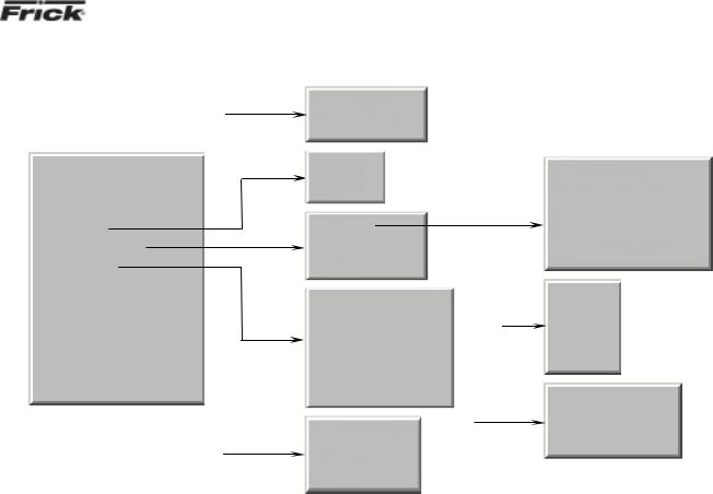
The above graphic represents the menu structure, or tree, of the Quantum™-LX screens. Use this tree when accessing the various screens. When this document is viewed electronically, passing the mouse pointer over each of the above names, and then clicking on it, will take
you directly to the page with that screen. Please note that this screen list is complete, and that certain screens may not be available as shown here, depending upon the enabled options.
S90-021 O (MAY 07) |
FRICK® QUANTUM™ LX COMPRESSOR CONTROL PANEL |
Page 6 |
OPERATION - ADAVNCED |
OPERATING DISPLAY SCREENS
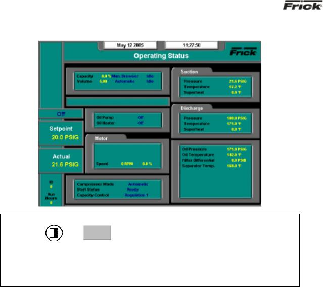
Operating Status
SCREEN NAME: Operating Status or Home.
ACCESSING: 
 Home
Home
DESCRIPTION: This is the default screen. When power is applied, this screen will appear. Also called the Home screen. The most important information about the compressor and the applicable subsystems operation is displayed here. This screen is shown when power is first turned on and when a key is pressed after the screen saver has turned off the backlight. The Operating Status screen is continuously updated and provides a variety of information with regard to the current condition and performance of the compressor unit and subsystem.
The following information is shown on this screen:
DATE - The actual date will be displayed in this box. The date must first be set correctly on the Configuration screen. Once set, the date will be automatically adjusted for at the end of each month, much like the calendar feature of most modern watches. The primary use of the date feature is to provide a date stamp for Warnings and Shutdowns. (See also TIME)
TIME - The actual time will be displayed in this box. The time must first be set correctly on the Configuration screen. The time will also need to be adjusted for those locations which observe Daylight Savings Time. The primary use of the time feature is to provide a time stamp for Warnings and Shutdowns. (See also Date)
SCREEN TITLE - This is the title for the screen that is showing. Each screen will have a title. The Quantum™ LX manuals will extensively refer to screens by these names. When referred to in these manuals, screen names will be shown in bold italic print, such as Operating Status.
COMPRESSOR MODEL - This is actually a rotating marquee. It will alternately display the model name of
the compressor (such as RWF) and will then rotate to show Frick® .
COMPRESSOR RUN STATUS -
•Off
•Running
•Starting
•Stopping
•Stopping - High Capacity
•Stopping - Pumpdown
PROCESS SETPOINT VALUE - This is the control setpoint maintained by the internal capacity control.
PROCESS ACTUAL VALUE - The actual reading of the pressure or temperature that was chosen as the compressor control setpoint.
ID - The value shown here is the number that has been assigned to this particular unit on the
Communications Setup screen.
RUN HOURS – The value shown here is the total number of hours that the compressor has been actually running, since the last start.

FRICK® QUANTUM™ LX COMPRESSOR CONTROL PANEL |
S90-021 O (MAY 07) |
OPERATION - ADVANCED |
Page 7 |
CAPACITY/VOLUME CONTROL BOX - Shows what is presently controlling the Slide Valve and from what source it was initiated. The following sources may be shown:
Capacity:
•Manual
•Automatic
•Remote -- Communications
•Remote -- IO
•Remote -- 4-20 Input
•Remote -- Sequencing
VOLUME:
•Manual
•Automatic
WARNING/SHUTDOWNS STATUS BOX - The Warning/Shutdowns Status is displayed in the indented box below the Capacity/Volume status box. This status box is blank with no message if there are no warnings or shutdowns present.
One of the following messages could be shown:
WARNING - This message flashes when a warning is present. A warning is a condition that requires operator acknowledgement and allows the compressor to continue to run if it is running.
SHUTDOWN - This message flashes when a shutdown is present. A shutdown is a condition that requires an operator to acknowledge it and causes the compressor to shut down. If the compressor cannot be stopped, it is minimally run in a protected state.
A Warning or Shutdown message indicates a Warning or Shutdown point has been reached, or exceeded.
When a Shutdown occurs, the display backlight will flash on and off to alert an operator of the shutdown. This visual alarm will help get the attention of the operator in a noisy engine room environment where audible alarms may not be heard. Pressing any key on the keypad will clear the flashing backlight.
OIL LUBRICATION DEVICE STATUS BOX - The operating status is shown for the following devices:
Oil Pump - (If selected in the Configuration) – The On or Off message is shown for the status of the oil pump. The Manual or Auto message is shown to indicate the position of the HAND-OFF- AUTO switch. If dual pump control was enabled in Configuration, the lead pump (either Oil Pump 1 or Oil Pump 2) is shown.
MOTOR STATUS BOX - The following items are shown:
Motor Amps - The actual amps.
%FLA - The percentage of the drive motor full load amperage rating that the motor is currently using. % (FLA x SF)
Kilowatts - This is the estimated value of the kilowatt usage of the compressor motor. It is based on the calculation of Motor Amps * Volts * 32 / 1000.
Recycle Delay - This message shows the remaining time in minutes for Recycle Delay. If the compressor has started and shuts down within the recycle time delay setpoint period, the Recycle Delay will prevent the compressor from starting until the delay time expires. This time delay is intended to prevent damage to the compressor motor from successive restarts.
Note: The remaining recycle delay time can be cleared from the Motor screen
COMPRESSOR STATUS BOX - Shows the present operating status of the compressor and from what source it has been initiated:
Compressor Mode - One of the following messages is shown:
•Manual - A compressor manual start or stop command was sent.
•Automatic - The compressor auto command was sent. The compressor starting and stopping is being controlled from automatic cycling control setpoints at the panel. The automatic cycling control setpoints of the active capacity control are used.
•Remote -- Communications - The compressor remote communications command was sent. The compressor starting and stopping is through the serial Com-2 channel.
•Remote -- IO - The compressor remote I/O command was sent.
•Remote -- Sequencing - The compressor remote sequencing command was sent.
Note: If there is a shutdown in response to a safety setting, a compressor in Remote or Automatic mode is placed into Manual mode requiring operator intervention.
Start Status - One of the following messages is shown:
Oil Heater - The On or Off message is shown for |
• |
Ready |
the status of the oil separator heater(s). |
||
|
• |
Start Inhibit In Shutdown |

S90-021 O (MAY 07) |
FRICK® QUANTUM™ LX COMPRESSOR CONTROL PANEL |
Page 8 |
OPERATION - ADAVNCED |
•Start Inhibit In Recycle Delay
•Start Inhibit High Discharge Temp.
•Start Inhibit High Oil Temperature
•Start Inhibit Low Separator Temperature
•Start Inhibit Slide Valve Too High
•Start Inhibit Still In Prelube
•Start Inhibit High Suction Pressure
•Start Inhibit High Suction/Discharge Differential Start Inhibit Permissive Start
•Start Inhibit Digital Auxiliaries
•Power Fail Restart
Capacity Control - One of the following messages is shown:
•Regulation 1
•Regulation 2
•Regulation 3
•Regulation 4
SUCTION PRESSURE & TEMPERATURE BOX - The following sensor information is displayed:
Suction Pressure - Is measured at the compressor inlet and the value is displayed along with the unit of measure.
Suction Temperature - Is measured at the compressor inlet and the value is displayed along with the unit of measure.
Superheat - The temperature of the gas at saturation temperature for a given period of time.
DISCHARGE PRESSURE & TEMPERATURE BOX - The following sensor information is displayed:
Discharge Pressure - Is measured at the compressor outlet and the value is displayed along with the unit of measure.
Discharge Temperature - Is measured at the compressor outlet and the value is displayed along with the unit of measure.
Superheat - Superheat is the term used to describe the difference between the vapor point (ie., the temperature at which the refrigerant evaporates at a given pressure) and the actual temperature of the refrigerant exiting the evaporator coil.
OTHER PRESSURES AND TEMPERATURE BOX - The following sensor information is displayed:
Oil Pressure - Is measured prior to entering the compressor and the value is displayed along with the unit of measure.
Oil Temperature - Is measured prior to entering the compressor and the value is displayed along with the unit of measure.
Filter Differential - If applicable, pressure drop across the oil filter. The main oil injection oil filter pressure drop value (differential) is displayed along with the unit of measure.
Separator Temperature - The Oil Separator Temperature value is displayed along with the unit of measure.
Process Temperature - If applicable, the Leaving Process Temperature value is displayed along with the unit of measure.
Balance Piston - If applicable, the Balance Piston pressure reading is displayed along with the unit of measure. This reading is a measurement of the presence at the Balance Piston.
FRICK® QUANTUM™ LX COMPRESSOR CONTROL PANEL |
S90-021 O (MAY 07) |
OPERATION - ADVANCED |
Page 9 |
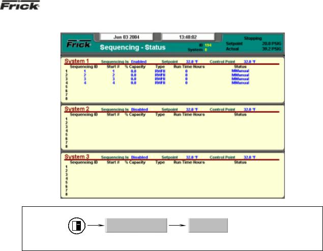
Sequencing
SCREEN NAME: Sequencing.
ACCESSING: |
Operating Values… |
Sequencing |
DESCRIPTION: This screen will be available if Sequencing is enabled in Compressor configuration. This is strictly a status screen, no values can be changed from here.
The following is a description of the Sequencing strategy:
Start/Stop
System Setup:
•Control Input – Suction Pressure
•Control Direction – Forward
•High Stage Link – Disabled
Start Procedure
Before starting a compressor, the master must determine that all the running compressors are loaded and that the Suction Pressure has risen to a point where an additional compressor is needed.
First, the master checks that either no compressors are running or all the running compressors average 90% capacity. If a running compressor is at less than 90% capacity but is in a Load Inhibit or Force Unload condition, for the purposes of this calculation it is assumed to be at 90% capacity.
If all the running compressors are loaded the master next begins comparing its Suction Pressure to the Autocycle Start setpoint. When the Suction Pressure rises above the Start setpoint, the start timer is initiated. If the start timer reaches the Autocycle Start Delay setpoint time and the Suction Pressure has remained above the Start setpoint for the entire time, the master attempts to start an additional compressor. If the Autocycle Start Delay setpoint is 0 minutes, the
master still waits 15 seconds before starting a compressor.
To determine which compressor to start, the master first sorts all the compressors in the system based on their start number, low to high. If two compressors have the same start number, the first one on the list remains ahead of the second. Next, the master starts at the top of the list and works down through list until it finds a compressor that is available to run. To be deemed available, a compressor must have good sequencing communications and its Compressor Mode and Capacity Mode must be set as Remote Sequencing. In addition the compressor must be off, and it cannot be in a Start Inhibit condition except for the Start Inhibit Slide Value Too High condition. The compressor with the lowest start number that also meets these conditions is then sent a start command. If no compressors are currently available to start, the master will continue checking until one becomes available or until the Suction Pressure drops below the Start setpoint.
After a compressor has been sent a start command, the master waits for that compressor to reach a Running state. If 3 minutes passes and the compressor has not yet begun to run, the master sends it a stop command. This compressor is then flagged as Unable to Start for 1 hour. After that time the master may again try to restart the compressor if additional capacity is needed. After a compressor begins running or after one fails to start and is sent a

S90-021 O (MAY 07) |
FRICK® QUANTUM™ LX COMPRESSOR CONTROL PANEL |
Page 10 |
OPERATION - ADAVNCED |
stop command, the master can begin the process of starting another compressor.
If the Difference is less than the Upper Proportional Band:
Stop Procedure |
Capacity Change = (Difference / Upper |
|
Proportional Band) * Upper Cycle Time |
If the Suction Pressure drops to a point where one of the running compressors is no longer needed, the master will stop the last compressor in the sequence list.
When the Suction Pressure drops below the Autocycle Stop setpoint, the stop timer is initiated. If the stop timer reaches the Autocycle Stop Delay setpoint time and the Suction Pressure has remained below the Stop setpoint for the entire time, the master attempts to stop one of the running compressors. If the Autocycle Stop Delay setpoint is 0 minutes, the master still waits 15 seconds before stopping a compressor.
To select the compressor to stop, the master also sorts all the compressors in the system according to their start number. Then the master starts at the bottom of the list and works up, looking for a running compressor that can be stopped. To be selected a compressor must have good sequencing communications and its Compressor Mode and Capacity Mode must be set as Remote Sequencing. In addition, the compressor’s run time must be greater than the compressor’s Minimum Run Time setpoint. If the Minimum Run Time setpoint is 0 minutes, a compressor can also be stopped if it is still in Starting mode. The compressor with the highest start number that meets these conditions is sent a stop command. If no compressors are currently available to stop, the master will continue checking until one becomes available or until the Suction Pressure rises above the Stop setpoint.
After a compressor has been sent a stop command, the master waits for that compressor to go to off. If 3 minutes passes and the compressor has not yet turned off, the master then flags this compressor as Unable to Stop for 1 hour. After that time the master may again try to stop the compressor. After a compressor goes to off or after one fails to stop within 3 minutes, the master can begin the process of stopping another compressor.
Load/Unload
System Setup:
Control Input – Suction Pressure
Control Direction – Forward
High Stage Link – Disabled
Load Procedure
If the master compressor’s Suction Pressure is above the Capacity Control setpoint, the master calculates the increase in capacity that is required. The calculation is as follows:
Difference = Suction Pressure – (Capacity Control Setpoint + Upper Dead Band)
If the Difference is greater than the Upper Proportional Band:
Capacity Change = Upper Cycle Time
After the capacity increase has been calculated, the master then finds the compressor whose capacity should be changed. To make this determination, the master sorts all the compressors based on their start number. Beginning at the compressor with the lowest start number, the master finds the first compressor on the list that is running but is not at its maximum capacity. A compressor is at maximum capacity if it is at 100 percent capacity or if it is in a Load Inhibit or Force Unload condition.
If the selected compressor is running the Quantum LX software, the capacity increase is added to the compressor’s current capacity. This new value is then sent to the compressor as its Capacity Command, and that compressor will try to increase its capacity to match the Command value.
If the selected compressor is controlled by a Quantum 1-4 or a Plus panel, the capacity increase is interpreted as the time period for a load pulse and is sent to the compressor as a load command. The slave compressor will then turn on its load output for the given number of seconds.
Unload Procedure
If the master compressor’s Suction Pressure is below the Capacity Control setpoint, the master calculates the decrease in capacity that is required. The calculation is as follows:
Difference = (Capacity Control Setpoint - Upper
Dead Band) – Suction Pressure
If the Difference is less than the Lower Proportional Band:
Capacity Change = (Difference / Lower Proportional Band) * Lower Cycle Time
If the Difference is greater than the Lower Proportional Band:
Capacity Change = Lower Cycle Time
After the capacity decrease has been calculated, the master then finds the compressor whose capacity should be changed. To make this determination, the master sorts all the compressors based on their start number. Beginning at the compressor with the highest start number, the master finds the last compressor on the list that is running and whose capacity is above its Minimum Capacity setpoint. If two compressors are currently running at or below their Minimum Capacity setpoints, the master will not allow any additional
FRICK® QUANTUM™ LX COMPRESSOR CONTROL PANEL |
S90-021 O (MAY 07) |
OPERATION - ADVANCED |
Page 11 |
compressors to unload. This will allow the Suction Pressure to continue to drop and will cause the master to turn off one of the unloaded compressors. If the master sees that only one compressor is running in its system, it will continue to unload the compressor down to the master’s Automatic Capacity Mode Minimum Slide Valve Position setpoint.
If the selected compressor is running the Quantum LX software, the capacity decrease is subtracted from the compressor’s current capacity. This new value is then sent to the compressor as its Capacity Command, and that compressor will try to decrease its capacity to match the Command value.
If the selected compressor is controlled by a Quantum 1-4 or a Plus panel, the capacity decrease is interpreted as the time-period for an unload pulse and is sent to the compressor as an unload command. The slave compressor will then turn on its unload output for the given number of seconds.
High Stage/Booster
The High Stage System Link setpoint is provided to tie a system of Booster compressors to a system of High Stage compressors. For example, if the Booster
compressors are setup on System #1 and the High Stage Compressors are on System #2, the High Stage System Link setpoint from System #1 would be set as System 2.
When the Booster System’s master wants to start the first Booster compressor, it first checks that a Booster compressor is available to run and then sends a signal to the High Stage System’s master telling it to start a High Stage compressor. If all the High Stage compressors are off, the High Stage System’s master will start its first compressor, regardless of what the High Stage Control Input is reading. When the Booster System’s master observes that a High Stage compressor is running, it will allow a Booster compressor to start.
After the first High Stage compressor begins to run, compressors in both systems will cycle on and off as their Control Inputs move up and down. The only stipulation to the control strategy is that one High Stage compressor must always remain on as long as at least one Booster compressor is running. If all the Booster compressors turn off, the High Stage compressor can then turn off as well.
S90-021 O (MAY 07) |
FRICK® QUANTUM™ LX COMPRESSOR CONTROL PANEL |
Page 12 |
OPERATION - ADAVNCED |
|
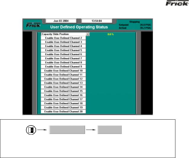
User Defined Operating Status |
SCREEN NAME: User Defined Operating Status. |
|
|
ACCESSING: |
Operating Values… |
User Defined |
DESCRIPTION: The purpose of this screen is to allow the user to assign additional analog channels to be more readily viewable. Since the main Operating Status (Home) screen is capable of only showing a limited number of pre-assigned analog values, it may be desirable for the user to have a method of viewing additional information that they can select, on a common screen. They may even select values that are already being displayed on the Operating Status screen, as well as values that are not shown there.
As an example of how this screen works, assume that in addition to the data that is shown on the Operating Status screen, the user would like to monitor the Capacity Slide Position, Suction Pressure and Motor Current. Notice that both the Suction Pressure and the Motor Current are already shown on the Operating Status screen, but the user would also like to see Capacity Slide Position on the same screen as these other two. In order to set this screen up this way, the user would highlight the Enable User Defined Channel 1 (or whatever channel they wish to use), by pressing the [Tab] key. Once the box is highlighted, use the [Enter] key to cause the possible settings for the channel to appear. Use the arrow keys to scroll through the list. When the selection that you want to use has been highlighted, press the [Enter] key to select it. Once selected, a value will appear to the right of the list, which corresponds to the analog value for that channel.
The following selections may be shown on this screen:
•Capacity slide position
•Volume slide position
•Suction pressure
•Discharge pressure
•Oil pressure (Compressor)
•Main Oil Injection pressure
•Economizer pressure
•Filter pressure
•Intermediate pressure
•Balance piston pressure
•System discharge pressure
•Suction temperature
•Discharge temperature
•Oil temperature compressor
•Oil separator temperature
•Process/Brine temperature leaving
•Process/Brine temperature entering
•Motor Current
•RPM
•User defined analog inputs #1 - #20
•Compressor Vibration - Suction
•Compressor Vibration - Discharge
•Motor Vibration - Shaft Side
•Motor Vibration - Opposite Shaft Side
•None
FRICK® QUANTUM™ LX COMPRESSOR CONTROL PANEL |
S90-021 O (MAY 07) |
OPERATION - ADVANCED |
Page 13 |
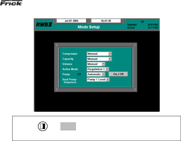
Mode Setup
SCREEN NAME: Mode Setup.
ACCESSING: 
 Mode
Mode
DESCRIPTION: The purpose of this screen is to allow the user to assign operational states (such as manual or automatic) to the various modes shown on the screen.
The following pull-down menus are shown here:
Compressor:
•Manual
•Automatic
•Remote -- Communications
•Remote -- IO
•Remote -- Sequencing
Capacity:
•Manual
•Automatic
•Remote -- Communications
•Remote -- IO
•Remote -- 4-20 Input
•Remote -- Sequencing
Volume:
•Manual
•Automatic
Active Mode:
•Regulation 1
•Regulation 2
•Regulation 3
•Regulation 4
Pump (if enabled):
A Pump On/Off indicator (blue text) is provided here to alert the user as to the actual status of the Oil Pump (if applicable). A drop down menu is also provided, and there are two states that can be selected for oil pump operation, they are:
•Manual
•Automatic
In Manual mode, the user has control over the running of the pump. To run the pump, simply observe the blue text indicator to ensure that the pump is not already running, and if not, then press the [On/Off] toggle button. The blue text indicator will change from Off to On. To stop the pump, press the toggle button again, and the pump indicator will change to Off.
If the pump is set to Automatic mode, the Quantum™ LX software program is controlling the pump operation. In this mode, if the toggle key is pressed, the mode will be changed from Automatic to Manual Mode, and the current state of the pump (digital output 3) will toggle also.
Dual Pump Sequence (if enabled):
•Pump 1 Lead
•Pump 2 Lead
S90-021 O (MAY 07) |
FRICK® QUANTUM™ LX COMPRESSOR CONTROL PANEL |
Page 14 |
OPERATION - ADAVNCED |
|
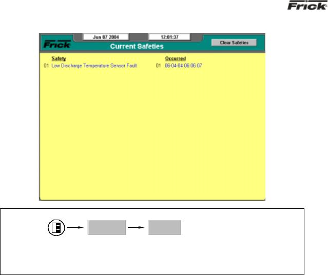
Safeties - History - Current Safeties |
SCREEN NAME: Current Safeties.
ACCESSING: |
Safeties… |
Current |
DESCRIPTION: The Current Safeties screen shows the Warnings and Shutdowns that have recently occurred (up to 50). When a warning or shutdown is triggered, a blue descriptive message shows on this screen. The date and time of the warning or shutdown occurrence is shown to the right of its description. The most recent message will appear on the top line of the screen with the oldest appearing at the bottom. When a Warning or Shutdown is logged to this screen, it will also be logged to the Safety History screen.
The following Current Safeties screen key is provided:
[Clear Safeties] - Selecting this key will clear all warnings and/or shutdowns from this screen. It also de-energizes the Warning and Shutdown output modules (digital outputs 23 and 24) to silence any warning annunciation device. This will also place a date/time stamp for the corresponding entry on the Safety History screen showing that the particular Warning or Shutdown was cleared. Clearing the entry on the Current Safeties screen, will not clear it from the Safety History screen.
To resume normal operation it will be necessary to go through the following steps:
1.Correct the condition(s) causing the warning.
2.Press the [ALARM SILENCE] key. (This action may precede correcting the condition(s) causing the warning). Or, go to step 3.
3.To clear or reset the Warnings/Shutdowns screen and turn off any warning annunciation
device, from the screen, press the [Clear Safeties] key. This will also clear the WARNING or SHUTDOWN message from the Operating Status screen.
4.If the conditions causing the warning have not been corrected or a new fault has occurred, a new WARNING or SHUTDOWN message will appear. The Safety History screen keeps a record of the warnings and shutdowns. This information will help troubleshoot persistent operational problems.
Refer to the Warnings/Shutdowns Message section for a list of all the possible conditions.
When a Shutdown occurs, the screen backlight will flash on and off to alert an operator of the shutdown. This visual indication will help get the attention of the operator in a noisy engine room environment where audible alarms may not be heard. Pressing any key on the keypad will clear the flashing backlight.
FRICK® QUANTUM™ LX COMPRESSOR CONTROL PANEL |
S90-021 O (MAY 07) |
OPERATION - ADVANCED |
Page 15 |
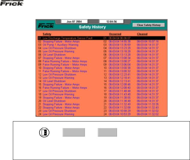
Safeties - History - Safety History
SCREEN NAME: Safety History.
ACCESSING: 
 Safeties…
  History
DESCRIPTION: The Safety History screen shows the warnings and shutdowns that have recently occurred (up to 50 maximum). When a warning or shutdown is triggered, a blue descriptive message shows on this screen. The date and time of the warning or shutdown occurrence is shown to the right of its description, followed by the date and time that the safety was cleared (if applicable, from the Current Safeties screen). The most recent message will appear on the top line of the screen with the oldest appearing at the bottom.
S90-021 O (MAY 07) |
FRICK® QUANTUM™ LX COMPRESSOR CONTROL PANEL |
Page 16 |
OPERATION - ADAVNCED |
|
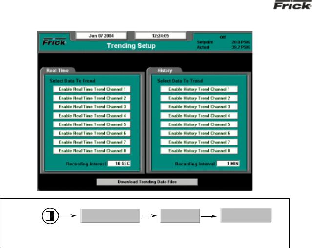
System Status -Trending - Trending Setup |
SCREEN NAME: Trending Setup.
ACCESSING: |
System Status… |
Trending… |
Trending Setup |
DESCRIPTION: This is the Trending Setup screen. Up to eight channels can be monitored in real time fashion (as the values are changing), and up to eight channels monitored as a history (long after they have happened).
The following setpoints are provided:
Real Time Recording Interval – The time interval that defines how often the trending data values are recorded.
History Recording Interval – The time interval that defines how often the trending data values are recorded.
To program this screen with the data you wish to trend, the user would highlight the Enable Real Time Trend Channel 1 (or whatever channel they wish to use), by pressing the [Tab] key. Once the box is highlighted, use the [Enter] key to cause the possible settings for the channel to appear. Use the arrow keys to scroll through the list. When the selection that you want to use has been highlighted, press the [Enter] key to select it. Once selected, the value for this channel will be automatically trended and shown on the Real Time Trending graph (or History Trending Graph), as well as on the Real Time Trending Data Log (Or History Trending Data Log).
The following list is the selectable values that may be shown on this screen:
•Capacity slide position
•Volume slide position
•Suction pressure
•Discharge pressure
•Oil pressure (Compressor)
•Main Oil Injection pressure
•Economizer pressure
•Filter pressure
•Intermediate pressure
•Balance piston pressure
•System discharge pressure
•Suction temperature
•Discharge temperature
•Oil temperature compressor
•Oil separator temperature
•Process/Brine temperature leaving
•Process/Brine temperature entering
•Motor Current
•RPM
•User defined analog inputs #1 - #20
•Compressor Vibration - Suction
•Compressor Vibration - Discharge
•Motor Vibration - Shaft Side
•Motor Vibration - Opposite Shaft Side
•None
The following screen command keys are provided:
Download Data Trending Files -
FRICK® QUANTUM™ LX COMPRESSOR CONTROL PANEL |
S90-021 O (MAY 07) |
OPERATION - ADVANCED |
Page 17 |
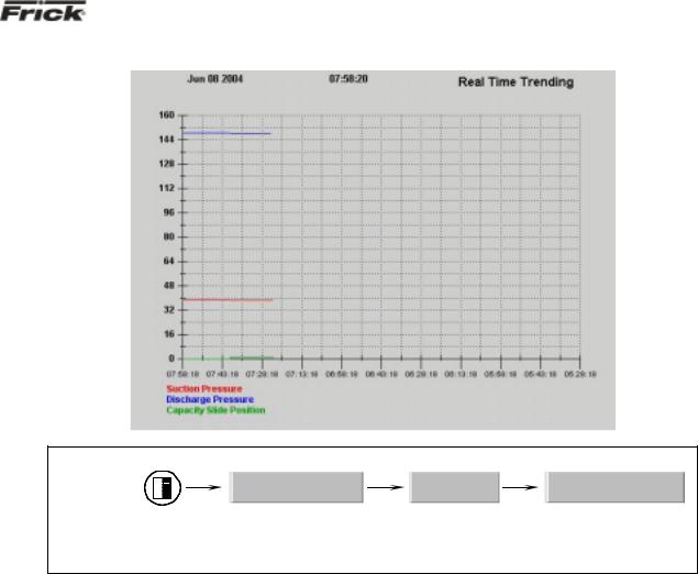
System Status -Trending - Real Time Trending
SCREEN NAME: Real Time Trending
ACCESSING: |
System Status… |
Trending… |
Real Time Trending |
DESCRIPTION: This is the Real Time Trending screen. This screen will display in a graphical chart format, the data values as selected on the Real Time Trending Setup screen. Each of the possible eight selectable channels will be shown at the bottom of the screen, each in a different color. The color data values displayed in the chart, correspond to the matching color of the trending channels at the bottom of the screen.
 Loading...