

Frick RWB II Plus Operation & Maintenance Manual

S70-200 OM/DEC 99
File: SERVICE MANUAL - Section 70
Replaces: S70-200 OM/MAR 99
Dist: 3, 3a, 3b, 3c
OPERATION - MAINTENANCE
MICROPROCESSOR CONTROL

S70-200 OM
Page 2
RWB II PLUS MICROPR OCESSOR CONTROL
OPERATION - MAINTENANCE
Contents
MICROPROCESSOR CONTROL PANEL ....................................................................................................................................3
KEYS AND KEY FUNCTIONS......................................................................................................................................................4
TO CHANGE THE ADJUSTABLE SETPOINTS: ...........................................................................................................................6
HOW TO DETERMINE ADJUSTABLE SETPOINTS: ...................................................................................................................7
TEMPERATURE-PRESSURE CONTROL PROGRAM (OPTION) .............................................................................................10
LEAD-LAG OPTION....................................................................................................................................................................12
COMMUNICA TIONS TROUBLESHOO TING ..............................................................................................................................13
HOW THE MICROPROCESSOR WORKS - SUMMARY -..........................................................................................................13
MULTIPLE COMPRESSOR SEQUENCING ...............................................................................................................................14
SUGGESTED PROGRAMMABLE CONTROLLER PROGRAM TO DECODE
MICROPROCESSOR OUTPUT DATA CODES ...................................................................................................................14
MICROPROCESSOR OUTPUT DATA CODE.............................................................................................................................15
MICROPROCESSOR TELECOMMUNICA TIONS .............................................................................................. ........................16
COMMUNICATIONS PROTOCOL SPECIFICATIONS:...............................................................................................................16
TROUBLESHOOTING THE RWB II PLUS MICROPROCESSOR..............................................................................................20
GENERAL INFORMATION .........................................................................................................................................................20
TROUBLESHOOTING FRICK SBC MICR OPR OCESSOR SYSTEM ........................................................................................20
TESTING MICRO-PANEL ALARMS/CUTOUTS .........................................................................................................................23
EPROM MEMORY I/C CHIP REPLACEMENT .............................................................................................. .............................25
SBC BOARD REPLACEMENT ...................................................................................................................................................25
MICROPROCESSOR DISPLAY REPLACEMENT......................................................................................................................25
OUTPUT FUSE REPLACEMENT...............................................................................................................................................25
SBC WIRING DIAGRAM.............................................................................................................................................................26
POINT-TO-POINT FIELD WIRING DIAGRAM ............................................................................................................................26
MICRO COMPONENT PLACEMENT DIA GRAM .......................................................................................................................27
RWB II PLUS TELECOMMUNICATIONS ...................................................................................................................................27
MICROPANEL ASSEMBLY WIRING DIAGRAMS.......................................................................................................................28
RECOMMENDED SPARE PARTS - CURRENT DESIGN ..........................................................................................................32
– Designates changes or new information on referenced pages. See page and topic for matching symbol.
RWB II PLUS MICROPR OCESSOR CONTROL
OPERATION
MICROPROCESSOR CONTROL PANEL
S70-200 OM
Page 3
The following must be read in addition to the Operation adn Start-up instructions in S70-200 IOM before attempting to start or operate the unit.
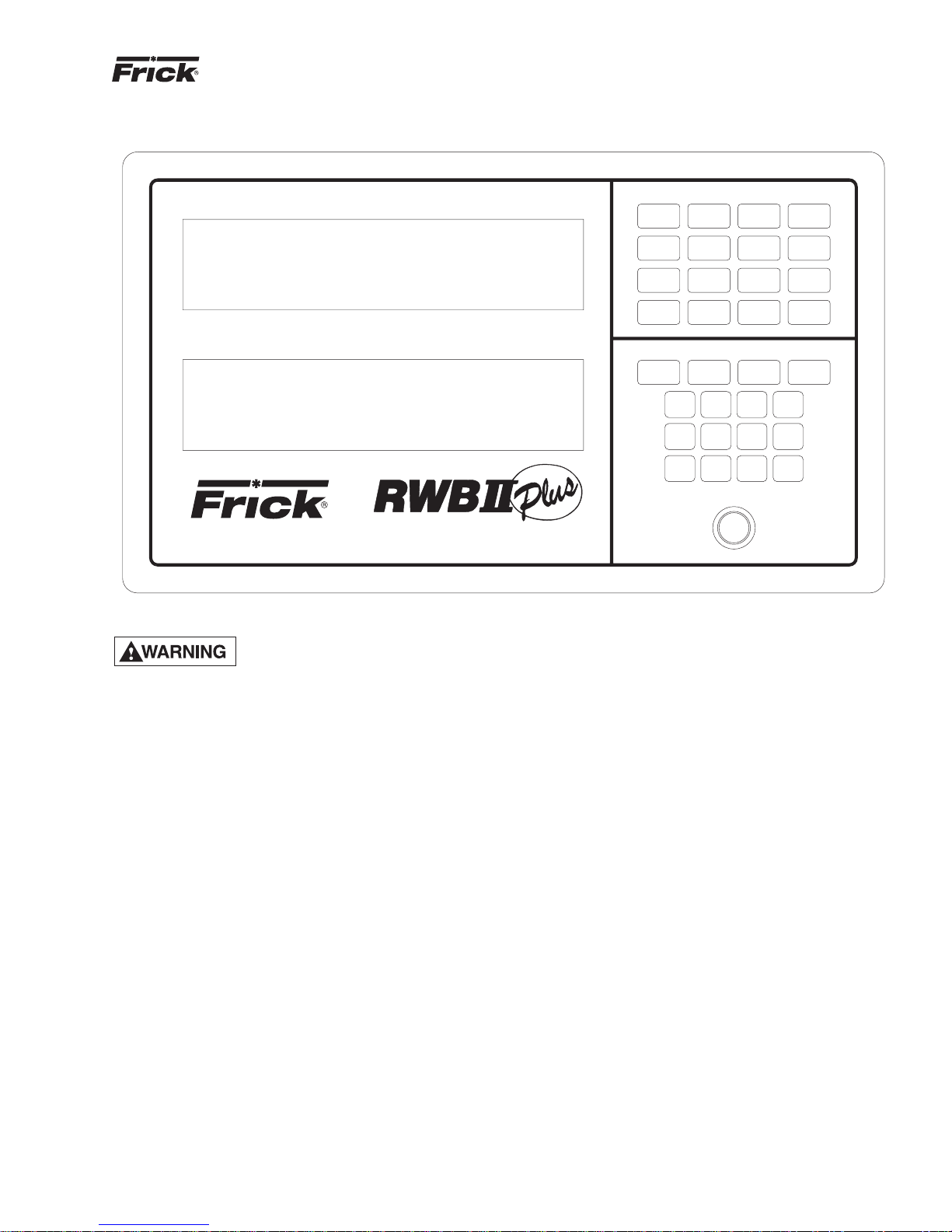
The RWB II PLUS compressor is controlled by a state-ofthe-art microprocessor control system. The microprocessor
continuously monitors the compressor unit’s condition and
operation. The microprocessor also directs instructions to
the various compressor unit subsystems.
The microprocessor has a membrane switch keyboard.
Pressing the keyboard in the area outlined as a ke y will cause
that function to be recognized by the microprocessor. The
keyboard has 32 membrane type keys.
In addition to the keyboard, there is an emergency stop b utton. Pushing the emergency stop will bypass the computer
and remove all power from the outputs.
RUN
STOP
FUNCTION
F1
F2
F3
F4
CLEAR
4
8
+/-
SLIDE STOP
AUTO
MANUAL
INCREASE
MANUAL
DECREASE
CHANGE
SLIDE VALVE
AUTO
REMOTE
MANUAL
LOAD
MANUAL
UNLOAD
SETPOINT ENTRY
STEP
1
2
5
6
9
*
EMERGENCY STOP
COMPRESSOR
REMOTE
START
ALARM
SILENCE
ENTER
3
7
0
This will shut down the compressor motor and all high voltage to the compressor auxiliary systems such as the oil
pump and liquid injection solenoid. THE EMERGENCY
STOP BUTT ON IS FOR EMERGENCY SHUTDOWN SITUA TIONS ONLY and MUST NOT BE USED TO ROUTINELY
SHUT OFF THE COMPRESSOR.
The microprocessor continuously monitors the state of the
battery which maintains setpoints and various other data. If
the battery voltage is low, the message “LOW BATTERY”
will flash in the lower right hand corner of the bottom display (see S70-200 IOM for description of battery backup).
The microprocessor hardware contains an output watchdog circuit. If the microprocessor should fail, this circuit will
disable (turn off) all outputs.

S70-200 OM
Page 4
RWB II PLUS MICROPR OCESSOR CONTROL
OPERATION
KEYS AND KEY FUNCTIONS
NOTE: The microprocessor will automatically return to
the main operating display after 60 seconds of keyboard nonactivity.
The [CHANGE] k ey rotates the dual displa y screen through
six display modes. The [CHANGE] key is also used to change
the status of various setpoints.
The [STEP] key steps or moves a set of flashing brackets
through the variable setpoints on the Adjustable setpoints
display, the Auto-cycle display, the Security display and the
Setback display. The setpoint enclosed within the flashing
brackets may be changed or updated. The [STEP] key is
also used when the annunciator display is selected to step
through the annunciator’s four information displays.
NOTE: The [ * ] key is used to step or move the flashing
brackets, described above, backwards.
The [ENTER] key is used to enter new setpoint limits.
The [CLEAR] ke y will reset an alarm or cutout indication on
the annunciator screen and will clear the microprocessor to
allow continued operation or restarting if all conditions have
returned to normal and no other control lockouts are in force.
The [NUMERIC KEYP AD] is used to introduce new setpoint
limits.
The [+/-] key is used to toggle between pounds per square
inch gauge (g) and inches of mercury (hg).
The [RUN], [STOP], and [REMOTE START] keys control
the starting and stopping of the compressor unit.
The [ALARM SILENCE] key will de-energize the alarm horn
output.
The [AUT O], [REMOTE], and [MANUAL] keys control the
operation of the compressor slide valve and mo v eab le slide
stop.
The [F1] function key will return the operator to the main
operating display. This function may be invoked at any time,
even during setpoint entry.
display mode. To change to a different display mode, press
the [CHANGE] k ey. The displa y modes in their order of rota-
tion are:
1. Operating display
2. Adjustable Setpoints display
3. Adjustable Setpoints display #2
4. Fixed Setpoints display
5. Annunciator display (4 pages)
6. Shutdown Record display
7. Freeze display
[F1] Operating display
[F2] Security display
[F3] Setback display
[F4] Auto Cycle display
NOTE: On initial powering of the microprocessor, and
any time power has been removed from the microprocessor, onl y the Operating, Setpoints, Ann unciator, and
Shutdown displays will display information. The freeze
display will appear as a dark screen. The Freeze display
will only be present after a compressor unit cutout and
power has not been interrupted to the microprocessor.
The cutout must be on a safety setpoint. When power is
lost to the micro, it will not show the freeze display.
OPERATING DISPLAY *
OPERATING DISPLAY: Thu 10-01-87 15:33:36
Suction Disch Oil Filter Compressor
20.0 g 180 g 170 g 01PSID MAN Mode
+015 F 140 F 135 F RUNNING
V Ratio S V Pos Pump %FLA Sep 132 F
4.6 090% OFF 080% HTR off
Auto D Auto L FORCED UNLD ALARM
C.C.=20.0 g LOW-BATTERY
*Display for illustrative purposes only.
The Operating display is continuously updated and pro vides
a variety of information in regard to the current status of the
compressor’s condition and performance.
The information furnished by the Operating display is as follows:
The DAY, DATE, and TIME are displayed at the top right of
the display.
The [F2] function key will call up the Security display. NO TE:
Press the [F2] key , as prompted b y the displa y, to return
to the previously selected display.
The [F3] function k ey will call up the Setback displa y. NO TE:
To exit the Setback display, press the [F1] key as
prompted by the display.
The [F4] function key will call up the Auto Cycle display.
NOTE: T o exit the A uto Cycle displa y, press the [F1] key
as prompted by the display.
The [DISPLAY BACKLIGHT] key will toggle the dual LCD
display backlights on and off. A preset delay will shut off the
backlight after ten minutes elapsed time.
The microprocessor has two liquid crystal displays in an 8
line by 40 character format, for a total of 320 characters.
There are 9 different display modes. When power is first
applied to the control panel, the unit will be in the Operating
NOTE: To set day, date, and time; see TO CHANGE THE
ADJUSTABLE SETPOINTS.
SUCTION - Suction Pressure and Temperature are mea-
sured at the compressor inlet and are, respectively, displayed
in pounds per square inch gauge (g) or inches of mercury
(hg) and degrees Fahrenheit.
DISCH - Discharge Pressure and Temperature are measured at the compressor outlet and are, respectively, displayed
in pounds per square inch gauge (g) and degrees Fahrenheit.
OIL - Oil Pressure and Temperature are measured prior to
entering the compressor and are, respectively, displayed in
pounds per square inch gauge (g) and degrees Fahrenheit.
FIL TER - Pressure drop across the oil filter. On the model
676 only, the bear ing oil filter pressure drop is displayed.
The main oil injection feed filter pressure drop is shown on a
unit mounted gauge.

RWB II PLUS MICROPR OCESSOR CONTROL
OPERATION
S70-200 OM
Page 5
COMPRESSOR - Compressor displays the status of the
compressor unit. The mode of operation will be indicated as
either manual (MAN MODE) when the [RUN] key has been
pressed, automatic (AUTO MODE) when Auto Cycle has
been activated, remote (RMT MODE) when the [REMOTE]
key has been pressed, or off (OFF MODE).
V RATIO - Volume Ratio is the ratio selected by the microprocessor to provide the highest efficiency at any given suction and discharge pressure condition. Immediately below
this, an information space has been provided to indicate
whether V ratio is in the automatic (AUTO) or the manual
(MAN) mode. The microprocessor will control this function
only in the automatic mode. To the right of the mode indicator, two other messages may appear:
I - Indicates V Ratio increase.
D - Indicates V Ratio decrease.
SV POS - Slide valve position is display ed as a percentage.
This percentage reflects the mechanical position of the slide
valve and does not reflect the percentage of full load operation. Immediately below this information, space has been
provided to indicate whether SV Pos is in the automatic
(AUT O), manual (MAN), or remote (RMT) mode . The microprocessor will control this function in the automatic mode.
To the right of the mode indicator, two other messages may
appear:
L - Indicates Slide Valve loading.
U - Indicates Slide Valve unloading.
PUMP - Pump displays the current status of the oil pump.
The display will read ON or OFF whenev er the HAND-OFF-
-AUTO switch is selected to AUTO and the compressor is
running.
% FLA - Percent Full Load Amps displa ys the percentage of
the drive motor full load amperage rating that the motor is
currently using.
NOTE: Consult Motor Manufacturer for the recommended duration of the Recycle Delay.
If the [RUN] key is pushed while the
unit is in Recycle Delay, the compressor will start at the end of the
delay period.
C.C. - Capacity Control, located at the bottom left of the
display, indicates the current capacity control suction pressure setpoint in pounds per square inch gauge (g) or inches
of mercury (hg).
ADJUSTABLE SETPOINTS DISPLAY *
ADJUSTABLE SETPOINTS: ID=[33] [10-01-87]
Cap. Control---[20.0 g ] Thu [15:33:36]
Lo Suct Cutout-[12.0 g ] Baud----[ 2400]
Lo Suct Alarm--[16.0 g ]
Hi Disch Cutout-[225 g ] Aux1[Alarm][NO]
Hi Disch Alarm--[215 g ] Aux2[Shutd][NC]
M.L.C. Stop Load--[095%] CT Factor-[078]
M.L.C. Force Unld-[100%] Recy.Delay-[30]
The Adjustable Setpoints display lists the adjustable setpoints which define the limits of the compressor package
operation. When these limits are reached, or exceeded,
alarm or compressor shutdown will occur. The inf orma
an
tion fur-
nished by the Adjustable Setpoints display is as follows:
CAP CONTROL - The Capacity Control setpoint, reported
in pounds per square inch gauge (g) or inches of mercury
(hg), controls the loading and unloading of the compressor
when SV POS is in the automatic (AUTO) mode.
LO SUCT CUTOUT - The Low Suction Pressure Cutout, reported in pounds per square inch gauge (g) or inches of
mercury (hg), will shut down the compressor if the suction
pressure drops to this limit, or lower, f or 120 seconds or longer.
SEP - Separator displays the oil separator temperature in
degrees Fahrenheit.
HTR - Heater displays the condition of the oil separator
heater(s), indicating ON or OFF.
ALARM/CUTOUT - An Alarm or Cutout message indicates
an Alarm or Cutout setpoint has been reached, or exceeded.
Rotate the display mode to the Annunciator display for details. In the e vent of a cutout, rotate to the Freeze display for
further details.
FORCED UNLD - A Forced Unload message indicates that
the percentage of motor full load amps has exceeded the
maximum limit and the microprocessor is unloading the compressor until the percentage FLA falls back to normal limits.
RECYCLE DELAY - A Recycle Delay message indicates
that the compressor has started and has shut down within
the time delay set point period. The Recycle Delay will prevent the compressor from starting until the delay time expires and is intended to prevent damage to the compressor
motor from successive restarts. During Recycle Delay, the
microprocessor will alternatively flash “RECYCLE DELAY”
and the remaining delay time in minutes.
*Display for illustrative purposes only.
LO SUCT ALARM - The Low Suction Pressure Alarm, reported in pounds per square inch gauge (g) or inches of
mercury (hg), will trigger a prealarm if the suction pressure
drops to this limit, or lower.
HI DISCH CUTOUT - The High Discharge Pressure Cutout,
reported in pounds per square inch gauge (g), will shut down
the compressor if the discharge pressure equals, or exceeds,
this setpoint.
HI DISCH ALARM - The High Discharge Pressure Alarm,
reported in pounds per square inch gauge (g) will trigger a
pre-alarm if the discharge pressure equals, or exceeds, this
setpoint.
M.L.C. STOP LOAD - The Motor Load Control Stop Load,
reported as a percentage of the motor full load amps (FLA),
will prevent the compressor slide valve from loading when
the setpoint is equaled, or exceeded. NOTE: Consult mo-
tor nameplate for recommended setpoint.
M.L.C. FORCE UNLD - The motor Load Control Force Un-
load, reported as a percentage of the motor full load amps
(FLA), will force the compressor to unload until the motor
full load amps (FLA) fall within 1% of the setpoint, or lower.
NOTE: Consult motor nameplate f or recommended setpoint.
S70-200 OM
Page 6
RWB II PLUS MICROPR OCESSOR CONTROL
OPERATION
ID - The ID number is a programmable identification code
used in telecommunications to access a specific compressor.
DATE - The Date displays the current date in the following
format: Month - Day - Year.
DAY - Day will display the current day of the week.
TIME - The Time displays the current time in the following
format: Hours - Minutes - Seconds. The time is in 24:00:00
hour clock format.
BAUD - Shows the baud rate of the RS422 communication
ports 1 and 2. Both ports are configured as follows: word = 8
bit, parity = none or even, stop = 1 bit. The communications
ports are programmable from 300 to 19200 baud.
AUX 1 and A UX 2 - May be configured f or either an alarm or
shutdown and with either a normally closed (NC) or normally open (NO) contact.
CT FACTOR - The Current Transformer Factor records the
proper current transformer factor to match the compressor
motor FLA rating to the current transformer primary rating.
The CTF factor is programmable and its correct value is
determined by the following formula:
CTF =
1024 x FLA (Full Load Amps)
10 x CT (Current Transformer Primary Amps)
EXAMPLE: FLA = 230 Amps
CT = 300 (300:5)
CTF =
1024x 230 = 78 (Round to whole number)
10 x 300
RECY. DELAY - The Recycle Delay displays the current
recycle delay setpoint in minutes. NOTE: Consult motor
manufacturer for recommended setpoint.
ADJUSTABLE SETPOINTS PAGE 2 *
ADJUSTABLE SETPOINTS Page 2:
Start Diff Press--[100g]
Dead Band--[1.0#]
Prop. Band-[10 %]
Cycle Time-[10 sec]
Low % FLA--[020 %]
Dead Band - This is a + (plus) or - (minus) value above or
below the setpoint at which the compressor will neither load
nor unload. A dead band of 1 is the default value. It is
adjustable between .5 lbs. to 5 lbs. in increments of .5. The
“Step” key is used to select this setpoint; then press the
“Change” key to toggle through the selections.
Cycle Time - Cycle time is the amount of time between the
beginning of each load/unload response. Ten seconds is
the default value. “Cycle Time” is adjustable between 5 and
30 seconds in 5 second intervals. The “Step” key is used to
select a setpoint; then press the “Change” key to toggle
through the selections.
Low % FLA - This setpoint is used to determine if the coupling has broken. 20% is the default value. It is adjustable
from 0 to 100% FLA. Use the “Step” k ey to select a setpoint;
then enter the desired setpoint and press the “Enter” key.
TO CHANGE THE ADJUSTABLE SETPOINTS:
Adjustable Setpoints are stored in RAM (random access
memory) and are easily changed in the field.
Adjustable Setpoints are lost if
power is interrupted and the battery
is not fully charged. To facilitate reentry, we suggest that a list of Adjustable Setpoints be
affixed to one end of the microprocessor cabinet for
reference. For your convenience, a blank Adjustable set-
points display which may be photocopied has been provided
(See page 10).
NOTE: The following procedure also applies to the c hanging of the Security, Setbac k, and A uto Cycle display setpoints.
1. Press the [CHANGE] key to rotate the display to the Ad-
justable Setpoints display.
2. Press the [STEP] key to move or step a set of flashing
brackets through the v arious setpoints. A setpoint is selected
for change or update when it is enclosed by the flashing
brackets.
NOTE: The DAY indicator, itself, will flash when selected
for change or update.
3. Having selected the setpoint to be changed, the [NU-
MERIC KEYPAD] may be used to enter the new setpoint.
NOTE: All digits must be entered, including zeros. For
example, (01.0).
NOTE: The D A Y, A UX 1, and A UX 2 setpoints, once selected,
are changed or updated by pressing the [CHANGE] key.
NOTE: Certain setpoints may be reported in either pounds
per square inch gauge (g) or inches of mercury (hg). To
toggle between (g) and (hg), having selected the setpoint,
press the [+/-] key to toggle between (g) and (hg).
4. In the event that an incorrect setpoint is keyed in all or
part, press the [CLEAR] key to restore the original setpoint.
Pressing the [CLEAR] key a second time will eliminate the
flashing brackets.
Proportional Band - This setpoint is used to determine the
amount of time the load/unload solenoid is energized, according to how far from the setpoint the actual control pressure is. The smaller the number, the longer a load/unload
signal will be sent. 10% is the def ault value . Selections are
2, 5, 10, 15, 20, or 25%. The “Step” ke y is used to select this
setpoint; then press the “Change” key to toggle through the
selections.
*Display for illustrative purposes only.
5. Having keyed the desired setpoint, press the [ENTER]
key. The new setpoint will be entered and the flashing brac kets will move or step to the next setpoint.
NOTE: A setpoint entry outside the parameters of the
Adjustable Setpoint display will be refused and the original Adjustable setpoint will be restored.
NOTE: To clear any time values [STEP] to the desired
setpoint, press [CHANGE] and then press [CLEAR].

RWB II PLUS MICROPR OCESSOR CONTROL
OPERATION
S70-200 OM
Page 7
HOW T O DETERMINE
ADJUSTABLE SETPOINTS:
Adjustable Setpoints should reflect values compatible with
normal system operation. Too high a Low Suction Pressure
Alarm setpoint may cause nuisance prealarms. Similarly,
cutout setpoints should not fall within what are considered
normal plant operation. As a rule of thumb, set the Low Suction Pressure Alarm 5 PSIG lower than the lowest normal
suction pressure. The Low Suction Pressure Cutout should
be 5 to 10 PSIG lower than the Low Suction Pressure Alarm
setpoint.
The High Discharge Pressure Cutout should be set at 90%
of the setting of the lowest high side relief valve. The High
Discharge
the Cutout.
The Capacity Control setpoint should be the equivalent of
the normal suction condition.
FIXED SETPOINTS: HIGH STAGE PRELUBE
OIL PUMP PGM/A
Hi Disch Cut----[212F]
Hi Disch Alarm--[194F] Liq Inj Con 113F
Hi Oil Temp Cut-[167F] Filter------[25]
Hi Oil Temp Alarm[158F]Oil Heater[113F]
Lo Oil Temp Cut--[49F] Lo Oil Cut-[030]
Lo Oil Temp Alarm[58F] Lo Oil Alrm[025]
The Fixed Setpoints display lists all fix ed setpoints, program
version, plus low oil alarm and low oil cutout setpoints. Fixed
Setpoints define the limits of acceptable compressor operation. Fixed Setpoints are factory determined, stored in programmed memory (PROM), and will remain in memory if
power to the microprocessor is interrupted.
HI DISCH CUT - The High Discharge Temperature Cutout,
reported in degrees Fahrenheit, will shut down the compressor if the discharge temperature equals or exceeds this
setpoint.
Pressure Alarm should be set 10 PSIG lower than
FIXED SETPOINTS DISPLAY *
PRELUBE, FULL LUBE, or CYCLING - Pump type will be
indicated.
PGM/ - Microprocessor Program version.
LIQ INJ CON - The Liquid Injection Control, reported in de-
grees Fahrenheit, will shut off the liquid refrigerant supply
to the compressor if the oil temperature equals or falls below this setpoint.
FILTER - The Oil Filter setpoint will trigger an alarm when
the differential pressure across the oil filter equals or exceeds 25 pounds per square inch (PSI) for 15 seconds, or
longer.
OIL HEA TER - The Oil Heater setpoint, reported in degrees
Fahrenheit, turns on the oil separator heater(s) when the oil
temperature equals or falls below this setpoint whenever
the compressor is NOT running.
Compressor Differential Cutout - The differential cutout
has been lowered from 55 lb to 25 lb. Cutout will occur after
five minutes. T o allo w operation at low differential pressures,
the micro will take the following steps:
A. Force unload the compressor to 50% and display an "F
Unload" when the oil pressure is within 10 lb of the main oil
injection port pressure and the slide valve position is greater
than 50%.
B. Prohibit the compressor from loading and display a "Ld
Inhib" message when the differential is within 15 lb of the
main oil injection port pressure.
Oil Pressure Alarm and cutout - Logic has been revised
to same logic as currently used on RXB/RXF. The new logic
is as follows:
Prelube and Cycling Oil Pump version when pump is not
running. Alarm will occur if oil pressure is 25 lb below discharge pressure or within 10 lb of suction pressure for 30
seconds. Cutout occurs if oil pressure is 30 lb below discharge pressure or if oil pressure is within 7 lb of suction
pressure for 10 seconds and alarm has already been set.
HI DISCH ALARM - The High Discharge T emperature Alarm,
reported in degrees Fahrenheit, will trigger a prealarm if the
discharge temperature equals or exceeds this setpoint.
HI OIL TEMP CUT - The High Oil Temperature Cutout, reported in degrees Fahrenheit, will shut down the compressor
if the oil temperature equals or exceeds this setpoint.
HI OIL TEMP ALARM - The High Oil Temperature Alarm,
reported in degrees Fahrenheit, will trigger a prealarm if the
oil temperature equals or exceeds this setpoint.
LOW OIL TEMP CUT - The Low Oil Temperature Cutout,
reported in degrees Fahrenheit, will shut down the compressor if the separator oil temperature equals or falls below this setpoint.
LOW OIL TEMP ALARM - The Low Oil Temperature Alarm,
reported in degrees Fahrenheit, will trigger a prealarm if the
separator oil temperature equals or falls below this setpoint.
HIGH STAGE or BOOSTER - Compressor application indicator.
Full Lube and Cycling Oil Pump version when oil pump is
running. Alarm occurs if oil pressure is within 10 lb of discharge pressure for 30 seconds. Cutout occurs when oil
pressure is within 5 lb of discharge pressure for 10 seconds
and oil pressure alarm has been set.
Cycling Oil Pump Control - The oil pump will cut off when
differential pressure between suction and discharge pressure is 55 lb or greater. Upon pump ter mination the above
cutout logic (pump not running) is utilized. Pump cut-in occurs when the differential pressure between suction and discharge is 45 lb or less. Oil pressure alarm and cutout logic
(pump running) begins after a 30 second delay which allows the oil pump to build pressure.
*Display for illustrative purposes only.
S70-200 OM
Page 8
RWB II PLUS MICROPR OCESSOR CONTROL
OPERATION
ANNUNCIATOR DISPLAY *
ANNUNCIATOR: PG-1 Thu 10-01-87 15:33:36
(Use STEP key to advance PAGE)
High Press. Cutout *********************
High Press. Alarm *********************
Low Press. Cutout *********************
Low Press. Alarm *********************
Oil Press. Cutout *********************
Oil Press. Alarm *********************
ANNUNCIATOR: PG-2 Thu 10-01-87 15:33:36
(Use STEP key to advance PAGE)
Hi Oil Temp Cutout *********************
Hi Oil Temp Alarm *********************
Low Temp Cutout *********************
Low Temp Alarm *********************
Disch. Temp Cutout *********************
Disch. Temp Alarm *********************
ANNUNCIATOR: PG-3 Thu 10-01-87 15:33:36
(Use STEP key to advance PAGE)
Comp. Auxiliary *********************
Pump Auxiliary *********************
Oil Level *********************
Comp. Differential *********************
Dirty Filter *********************
ANNUNCIATOR: PG-4 Thu 10-01-87 15:33:36
(Use STEP key to advance PAGE)
Aux. 1 (Alarm) *********************
Aux. 2 (Shutdown) *********************
Low Motor Amps
Sensor Fault
When a prealarm or cutout occurs, a flashing ALARM or
CUTOUT indicator will appear in the lower right hand cor-
ner of the Operating display. To determine the fault, rotate to
the Annunciator display by pressing the [CHANGE] key.
The Annunciator display lists all ke y operative points on f our
sequential displays. These displa ys can be rotated from page
#1 through page #4 by pressing the [STEP] key. When a
prealarm or cutout is triggered, the pertinent point will flash,
and the time of the occurrence will be recorded to the right
of the alarm. Prealarms are self-clearing. At this time the
alarm will stop flashing, but the time of the first occurrence
will still be recorded to the right of the alarm. Pressing the
[CLEAR] key while at the Annunciator display will clear all
alarms and/or cutouts.
In order to restore the Annunciator display and resume normal operation it will be necessary to go through the following steps:
1. Correct the conditions causing the alarm.
4. Press [F1] to call up the Operating display. If the condi-
tions causing the alarm have not been corrected or a new
fault has occurred, a new ALARM or CUT OUT message will
appear.
NOTE: Use of the Emergency Stop Button may trip one
or more alarm setpoints.
SHUTDOWN RECORD DISPLAY *
SHUTDOWN RECORD: Thu 10-01-87 15:33:36
(Use STEP key to advance PAGE)
Hi Oil Temp Cutout Wed 09-30-87 16:22:54
Comp Auxiliary Sat 08-22-87 09:47:02
Low Temp Cutout Thu 08-20-87 11:17:33
Pump Auxiliary Mon 08-17-87 18:53:11
Disch. Temp Cutout Tue 07-14-87 06:22:09
Oil Pres Cutout Fri 07-08-87 14:06:21
The Shutdown Record display keeps a record of the last six
shutdowns (cutouts). This information will help troubleshoot
persistent operational problems. The most recent cutout will
appear on the top line of the display with the oldest appearing
on the last or bottom line. When a cutout occurs, all inf ormation is moved down one line and the new cutout appears at
the top. When the displa y is full, the oldest record is dropped
off the display and is not retained in memory. The information presented is echoed from the Annunciator display; providing the type of cutout, the day, the date, and the time.
NOTE: This information will not be lost due to power
failure.
FREEZE DISPLAY *
FREEZE DISPLAY: Thu 10-01-87 15:33:36
Suction Disch Oil Filter Compressor
20.0 g 225 g 170 g 01PSID OFF Mode
+015 F 140 F 135 F RECYCLE
V Ratio S V Pos Pump %FLA Sep 132 F
4.6 090% OFF 080% HTR off
Auto Auto CUTOUT
C.C.=20.0 g
The Freeze displa y has the same appear ance and contains
the same information as the Operating display. (For a description of the information presented by the Freeze displa y,
refer to the Operating display.) The Freeze display freezes
the information of the Operating display A T THE MOMENT
OF A COMPRESSOR CUTOUT. The information on the
Freeze displa y can help the operator to identify the cause of
a fault which occurred when no one was present. The Freeze
display will retain the information generated by a cutout until a new cutout occurs or power is removed from the microprocessor.
Do not confuse the Freeze display
with the Operating display . In order
to avoid confusion remember that
the displayed information on the Operating display is
constantly being updated and changed. The Freeze display is fixed and FREEZE DISPLA Y appear s in the upper
left hand corner of the display.
2. Press the [ALARM SILENCE] key. (This action may pre-
cede correcting the conditions causing the alarm).
3. To clear or reset the Annunciator pages, press the
[CLEAR] key. This will also clear the ALARM or CUTOUT
indicator from the Operating display.
NOTE: The Freeze display will appear as a blank screen
when power is initially furnished to the unit, and it will
return to a blank screen anytime power is removed fr om
the microprocessor.
*Display for illustrative purposes only.

RWB II PLUS MICROPR OCESSOR CONTROL
OPERATION
S70-200 OM
Page 9
SECURITY DISPLAY *
SECURITY DISPLAY: Thu 10-01-87 15:33:36
Setpoints Access---[Enabled ] Keyboard
Enter Access Code---[*****]
Press F2 To Exit
The [F2] function key will call up the Security display. The
Security display allows the operator to either enable or disable the microprocessor’s keyboard and, thereby, prevent
unauthorized tampering with the various adjustable setpoints.
When enabled, the microprocessor ke yboard is fully operative and the security lockout is not in effect. When disabled,
the keyboard is rendered partially nonfunctional. All displa ys
will still be accessible through the keyboard. If any attempt
is made to enter new adjustable setpoints, ho w e v er, the microprocessor will default to the Security display.
TO ENABLE THE KEYBOARD, press the [STEP] key so
that the brackets beside Enter Access Code flash, key the
proper five digit access code, and press [ENTER]. The Setpoints Access will toggle from disabled to enabled and adjustable set point entry is now possible.
TO DISABLE THE KEYBOARD, press the [F2] function key
to call up the Security display. Press the [STEP] key until
the brackets beside Enter Access Code flash, k ey the proper
five digit access code, and press [ENTER]. Now, press the
[STEP] key until the brac kets beside Setpoints Access flash
and press the [CHANGE] key to toggle from enab led to disabled.
TO CHANGE THE ACCESS CODE, press the [F2] function
key to call up the Security display. Press the [STEP] key
until the brackets beside Enter Access Code flash, key the
proper five digit access code, and press [ENTER]. Now,
select the Enter Access Code a second time by pressing
the [STEP] key until the brackets beside Setpoints Access
flash, key in the new five digit access code, and press [EN-
TER].
NOTE: Power loss will not effect the Security display.
NOTE: IF NO ACCESS CODE WAS ENTERED AND THE
DISABLED COMMAND WAS SELECTED, THE ACCESS
CODE IS [00000].
LOST OR FORGOTTEN ACCESS CODE: Consult Frick
Company for assistance.
SETBACK DISPLAY *
SETBACK DISPLAY: Thu 10-01-87 15:33:36
Press F1 To Exit
Setback Setpoint-[05.0 g ] Active-[No ]
Start Stop Start Stop
Mon-[--:--]-[06:00] Fri-[16:00]-[--:--]
Tue-[--:--]-[--:--] Sat-[--:--]-[--:--]
Wed-[--:--]-[--:--] Sun-[--:--]-[--:--]
Thu-[--:--]-[--:--]
*Display for illustrative purposes only.
The [F3] function key will call up the Setback display. The
Setback feature enables automatic operation at two separate suction conditions on a preset time schedule. Having
entered the desired Setback setpoint, enter the start and
stop time or times, and select Active: (Yes) or (No).
NOTE: To change the Setback setpoints, refer to “TO
CHANGE THE ADJUST ABLE SETPOINTS”
AUTO CYCLE DISPLAY *
AUTO CYCLE Thu 10-01-87 16:33:36
DISPLAY: Press F1 To Exit
Suction Pressure--------[20.0 g ]
Compressor Start--------[20.0 g ]
Compressor Stop---------[18.0 hg]
Minimum Slide Valve-----[00%]
Auto Cycle Active-------[No ]
The Auto Cycle display provides for independently adjustable setpoints to turn the compressor on and off in response
to the suction pressure or as an adjustable setpoint to limit
the minimum slide valve position.
NOTE: To change the Auto Cycle setpoints, refer to
“TO CHANGE THE ADJUSTABLE SETPOINTS”
SUCTION PRESSURE - Constantly monitors and displays
the suction pressure in pounds per square inch gauge (g) or
inches of mercury (hg).
COMPRESSOR START - Compressor Start-up will bring
the compressor back on line when the suction pressure rises
to the displayed setpoint.
COMPRESSOR STOP - Compressor Stop will shut down
the unit if the suction pressure drops to or below the displayed setpoint limit. NOTE: This limit must be set higher
than Low Suction Pressure Cutout and the Low Suction Pressure Alarm setpoints.
MINIMUM SLIDE VALVE - Minimum Slide Valve Position,
shown as a percentage, will limit the slide valve position to
the displayed setpoint.
AUTO CYCLE ACTIVE - Indicates whether Auto Cycle is
active (YES) or not active (NO). Press the [CHANGE] key
while at this setpoint to change the status. Upon deactivation, the compressor will return to the previous mode of operation.
ANALOG OFFSET DISPLAY*
ANALOG OFFSET:
Suc Disch Oil Sep Filt Spare Econ
Temp +0 +0 +0 +0 +0.0
Pres +0.0 +0 +0 +0 +0
Channel 10 12 13
Press +0 +0 0
The Analog Offset Display is accessed by pressing +/- key.
All analog values can be offset + or - 3 to 9 units depending
on which value is being adjusted. Use the [STEP] key to
step to the desired setpoint. Press the [CHANGE] key to
change the value of the offset by 1. The actual analog value
will be displayed on the top line of the display. The “Econ”
and channels 10, 12, 13 are displayed but do not pertain to
the standard program.

S70-200 OM
Page 10
RWB II PLUS MICROPR OCESSOR CONTROL
OPERATION
Sensor Fault Failure - A “Sensor F ault” cutout was added
to the program to stop the compressor if a temperature or
pressure sensor is at its minimum or maximum limit for 5
seconds. The following channels and conditions will cause
this cutout:
O
F)
F)
O
F)
Channel 1 - Suction Temp Low or High (-67 to 113
Channel 2 - Low or High Discharge Temp (32 or 212OF)
Channel 3 - Low or High Oil Temp (0 or 180
O
Channel 4 - Low or High Separator Temp (0 or 180
Channel 6 - Low or High Oil Pressure (<0 g or 285 g)
Channel 8 -
Low or High Discharge Pressure (<0 g or 285 g)
Channel 9 - Low Suction Pressure (29 hg only)
Pulse Load Signal at 100% Slide Valve Position - This
new feature will stop loading the compressor when 100%
slide valve is display ed. The load signal will pulse for 2 seconds every minute when the slide valve is at 100% and the
pressure is above setpoint.
TEMPERA TURE-PRESSURE CONTROL
PROGRAM (OPTION)
NOTE: The following displays are provided only when
the Temperature-Pressure Control Program option has
been ordered with the RWB II Plus Rotary Screw Compressor Unit.
SETPOINTS DISPLAY PAGE 1 *
CONTROL - This setpoint is used to select either Pressure
Capacity Control or Temperature Capacity Control. NOTE:
There are only two setpoints, press f or pressure capacity control and temp for temperature capacity control.
CC - The capacity control setpoint is for normal operation,
not setback.
CUTOUT -This setpoint will stop the compressor if the suc-
tion pressure drops below the pressure setpoint for 90 seconds or if the CC Temperature drops below the temperature
setpoint. There is no time delay on the temperature cutout.
ALARM - An alarm will be activated if the suction pressure
drops below the pressure setpoint or if the CC Temperature
drops below the temperature setpoint. There is no time delay for either.
PB - The Proportional Band (PB) is used to determine the
amount of time the load/unload solenoid is energized, according to how far away from the setpoint the actual control
pressure or temperature is. The smaller the number , the more
load/unload will be sent. A PB of 10% is def ault. It is adjustable to 2, 5, 10, 15, 20, or 25 percent.
DB - The Dead Band (DB) is a + (plus) or - (minus) value
above or below the setpoint which the compressor will neither load nor unload. It is adjustable between .5 and 5.0
psig or degrees, in increments of .5 units.
SETPOINTS PAGE 1 Capacity Control=Press
C.C. CUTOUT ALARM PB DB CT
Press 25.3g 01.3g 05.3g 10 1.0 10
Temp +40.0F +32.0F +33.0F 10 0.5 10
offset-act
Sup Heat-Alarm-10F-no
Sep Cond-Alarm-10F-no
* Display for illustrative purposes only.
The Setpoints Display is accessed by pressing the
[CHANGE] key.
ADJUSTABLE SETPOINTS FORM
ADJUSTABLE SETPOINTS: ID = [ ] [ - - ]
Cap. Control ———[ ] Thu [ : : ]
Lo Suct Cutout ——[ ] Baud ———————[ ]
Lo Suct Alarm ———[ ]
Hi Disch Cutout ——[ ] Aux 1 [ ] [ ]
Hi Disch Alarm ——[ ] Aux 2 [ ] [ ]
CT - The Cycle Time (CT) setpoint is the amount of time
between the beginning of each load/unload response. It is
adjustable to 5, 10, 15, 20, 25, or 30 seconds.
Use the [STEP] key to step to the desired setpoint, then
press the [CHANGE] key to change the CC , PB, DB and CT
values. Enter the desire value for the remaining setpoints
and press [ENTER] when complete.
M.L.C. Stop Load —[ ] CT Factor ———[ ]
M.L.C. Force Unld —[ ] Recy. Delay ——[ ]
Photocopy and fill in applicable data for your unit. Retain for reference if reentry is required.
 Loading...