

Page 1

Form 090.610-M (MAY 2016)
Please check www.johnsoncontrols.com/frick for the latest version of this publication.
MAINTENANCE
File: SERVICE MANUAL - Section 90
Replaces: 090.610 - M (DEC 2012)
Dist: 3, 3a, 3b, 3c
MAINTENANCE
FRICK® QUANTUM™
EVAPORATOR
CONTROL PANEL
Version 3.1x
Page 2

090.610-M (MAY 2016)
Page 2
QUANTUM™ LX EVAPORATOR CONTROL PANEL
MAINTENANCE
TABLE OF CONTENTS
SECTION 1
INTRODUCTION TO THE QUANTUM™ EVAPORTOR CONTROL SYSTEM ................................................................3
SECTION 2
REMOTE PANEL.....................................................................................................................................................9
SECTION 3
Q5 CONTROLLER..................................................................................................................................................13
SECTION 4
Q4 CONTROLLER..................................................................................................................................................23
SECTION 5
DIGITAL BOARD..................................................................................................................................................29
SECTION 6
ANALOG BOARD..................................................................................................................................................35
SECTION 7
SERVICE SCREENS...............................................................................................................................................41
SECTION 8
TROUBLESHOOTING.............................................................................................................................................49
SECTION 9
EVAPORATOR CONTROL PANEL AND REMOTE PANEL DRAWINGS........................................................................51
SECTION 10
REPLACEMENT PARTS..........................................................................................................................................59
THE FOLLOWING PUBLICATIONS ARE AVAILABLE FROM THE JOHNSON CONTROLS® WEBSITE jci.com
090.612-O Frick® Quantum™ LX Evaporator Control Panel Operation
090.610-CS Frick® Quantum™ LX Evaporator Control Panel Communications Setup (setup and wiring for data communication using available protocols)
090.610-M Frick® Quantum™ LX Evaporator Control Panel Maintenance (repair and troubleshooting)
Page 3

QUANTUM™ LX EVAPORATOR CONTROL PANEL
MAINTENANCE
090.610-M (MAY 2016)
SECTION 1
INTRODUCTION TO THE QUANTUM™ EVAPORATOR
CONTROL SYSTEM
Page 3
Page 4

090.610-M (MAY 2016)
Page 4
INTRODUCTION TO THE QUANTUM™ LX EVAPORATOR CONTROL SYSTEM
QUANTUM™ LX EVAPORATOR CONTROL PANEL
MAINTENANCE
INTRODUCTION
The Quantum™ LX Evaporator system consists of two
major control components:
• The Quantum™ LX Evaporator Control Panel
• Evaporator Remote Panel(s)
With the Quantum™ LX Evaporator system version
3.0x and later, a single Evaporator Control Panel can
control up to ten remote panels with each remote capable of handling three Evaporator units, for a total
possible of thirty units. It is also capable of Ethernet
access, which can be viewed remotely through any
web browser, or the optional Frick™ Evaporator Operator Interface Panel.
The Frick® Quantum™ LX Evaporator control system
consists of ve major areas:
QUANTUM™ LX CONTROL PANEL ENCLOSURE
The Frick® Quantum™ LX Evaporator control
panel enclosure is congured to make it as
standard as possible. Since there are nearly
an innite number of possible congurations
and options, this manual will describe the
most common features and arrangements. It
is always best to refer to the wiring diagrams,
panel layouts, and operational documentation
that is included with each unit for exact details regarding equipment operation.
• Power Supply - Provides the necessary
operating voltages for the proper operation of all control components. Additional
information about the power supply can
be found later in this manual.
• Quantum™ Controller - Evaporator
panels are currently supplied with the Q5
control board, but numerous units with
the previous version known as the Q4
board also exist. This manual will include
information for both of these boards.
Both the Q4 and Q5 boards run a software program that communicates with
all Remote Panels, which in turn control the Digital and Analog boards within
those panels. This communication allows
the controller to read the status of all
the I/O boards, and display the data either on its own display, a Web Browser,
or the optional Standard Interface Panel.
The Quantum™ controller acts on this
data, and provides the necessary con-
trol information to the I/O boards to provide
the appropriate control of all input and output
signals, based upon the conguration of installed features and options of the Evaporator
package. Interaction to the outside world can
be achieved through industry-standard communications protocols. Additional information
is located under the Q4 (or Q5) CONTROLLER
section found later in this manual. The Quantum™ controller, when loaded with the operating system, is then known as the Quantum™
LX Evaporator system.
EVAPORATOR REMOTE PANEL
The Remote Panel contains the I/O that will control
up to three Evaporator units. Up to ten Remote
Panels may be connected to the Quantum™ LX
Control panel via RS-485 communications, for a
maximum total of thirty units.
• Power Supply - Provides the necessary operating voltages for the proper operation of all
control components. Additional information
about the power supply can be found later in
this manual.
• Digital Input / Output Boards - Digital (on/off)
signals are sent and received by these boards.
The output signals are used for energizing
solenoids, valves, contactors, relays, etc.,
and the input signals are used to sense the
condition of switches, relay contacts, auxiliary
contacts, etc. This board runs an independent
software program from the Quantum™ LX to
control devices, and communicates the status
of all devices back to the Quantum™ LX. Additional information about the Digital Boards
is located under the DIGITAL BOARD section
found later in this manual.
• Analog Input / Output Board - Analog (variable) signals are sent and received by this
board. The output signals are used for controlling damper motors, modulated valves,
etc., and the input signals are used to read
the values being sent from pressure transducers, temperature sensors, etc. This board runs
an independent software program from the
Quantum™ LX to control devices, and communicates the status of all devices back to
the Quantum™ LX. The analog board contains
24 analog inputs, and 8 analog outputs. Additional information about the Analog board
is located under the ANALOG BOARD section
found later in this manual.
Page 5

QUANTUM™ LX EVAPORATOR CONTROL PANEL
MAINTENANCE
090.610-M (MAY 2016)
Page 5
GENERAL INFORMATION
The components within the control panel can be
inadvertently damaged by static electricity or mis-
handling. Only qualied technicians should directly
handle these components.
1. DO NOT attempt to make corrections to the
power supply without shutting off the power
to the control panel. Accidental shorts can
irreparably damage the processor boards or
the display screen.
2. DO NOT HANDLE the panel boards when their
cables are disconnected without rst attaching a properly grounded wrist ground strap to
prevent static electrical discharge from your
body.
Most problems encountered with the microprocessor
and control circuits will be the result of a wiring fault, a
blown fuse, faulty I/O module or failure of a peripheral
control such as a solenoid coil or a pressure transducer.
Faults in the computer, while possible, are unlikely. If a
fault develops in the computer, the probability is that
all functions will cease and the display screen will go
blank. The control system consists of an AC (high voltage) side, which can be either 120 volts, or 230 volts,
and a DC (low voltage) side. The AC side actuates solenoids, relays, alarms, and other electromechanical
functions. The DC side operates the computer and its
various sensors.
WHAT TO DO BEFORE CALLING THE FACTORY
Many times when a suspected Quantum™ problem is
called in to the factory, not enough information is provided for the service personnel to assist in solving the
problem. This is because the caller most likely is not
aware of the type of information that would be useful to factory personnel in helping to identify and correct the problem. An example of this is the statement
that the Quantum™ is not booting (the main processor
board is not starting). Unfortunately, this description is
usually vague and only means that there is nothing on
the display. A blank screen could be the result of many
different problems. The following is a list of possible
reasons for no display:
• No power
• Loose or Faulty Display Cable or Inverter Cable
• Bad Display
• Bad Backlight Inverter (on CCFT style displays)
• Bad Backlight Fluorescent Tube (on CCFT style
displays)
• Wrong Combination of Display, Cable, Inverter, or Software
• Faulty CPU Board
When working within the panel, the AC high voltage
side, which can be either nominal 120 VAC or nominal 230 VAC, CAN CAUSE INJURY OR DEATH.
To troubleshoot the low-voltage side of the control circuits, it is necessary to have the following tools:
1. Accurate digital multimeter (capable of reading to DC/AC, mA to the hundreds place)
2. Small wire stripper
3. Small screwdriver (with insulated shaft)
4. Small snip nose pliers
5. Wrist Grounding strap
6. Static free grounded work surface
Note: Proper panel voltage refers to the AC (high voltage) that has been supplied to the panel, which could
be either nominal 120 VAC or nominal 230 VAC.
Before calling the factory for assistance, review the information on the following pages and try to discover
and resolve your Quantum™ LX problem. The actual
cause of most problems is usually not with the Quantum™ board itself, but with something external. However, on the rare occasion that the problem has been
identied as being the Quantum™ board, use the following section as a guideline for replacing it.
Page 6
090.610-M (MAY 2016)
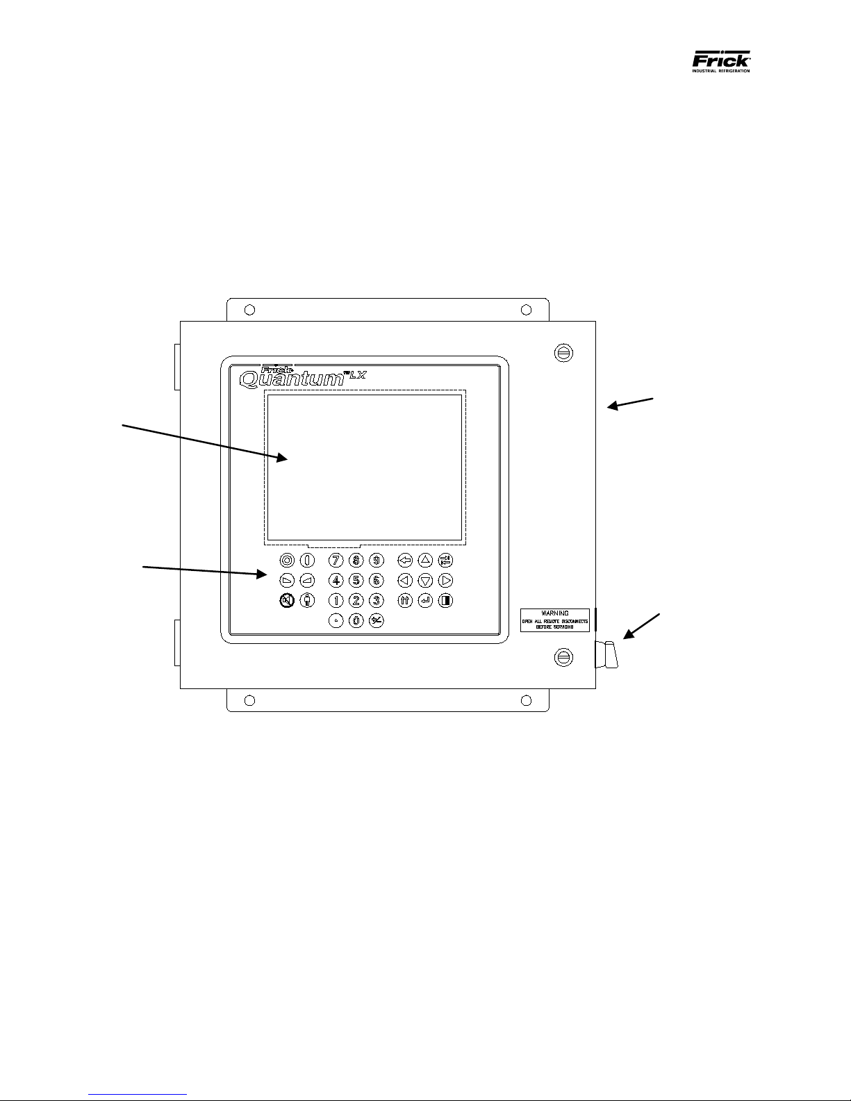
Enclosure
Display
Keypad
Control Power
Switch
Page 6
QUANTUM™ LX EVAPORATOR CONTROL PANEL
MAINTENANCE
QUANTUM™ EVAPORATOR CONTROL PANEL
The following pictorial shows front the Control Panel portion of the unit, and will appear the same for both a Q4 or Q5 control,
and shows the following components:
• Enclosure
• Display
• Keypad
• Control Power Switch
Front of Enclosure
Page 7
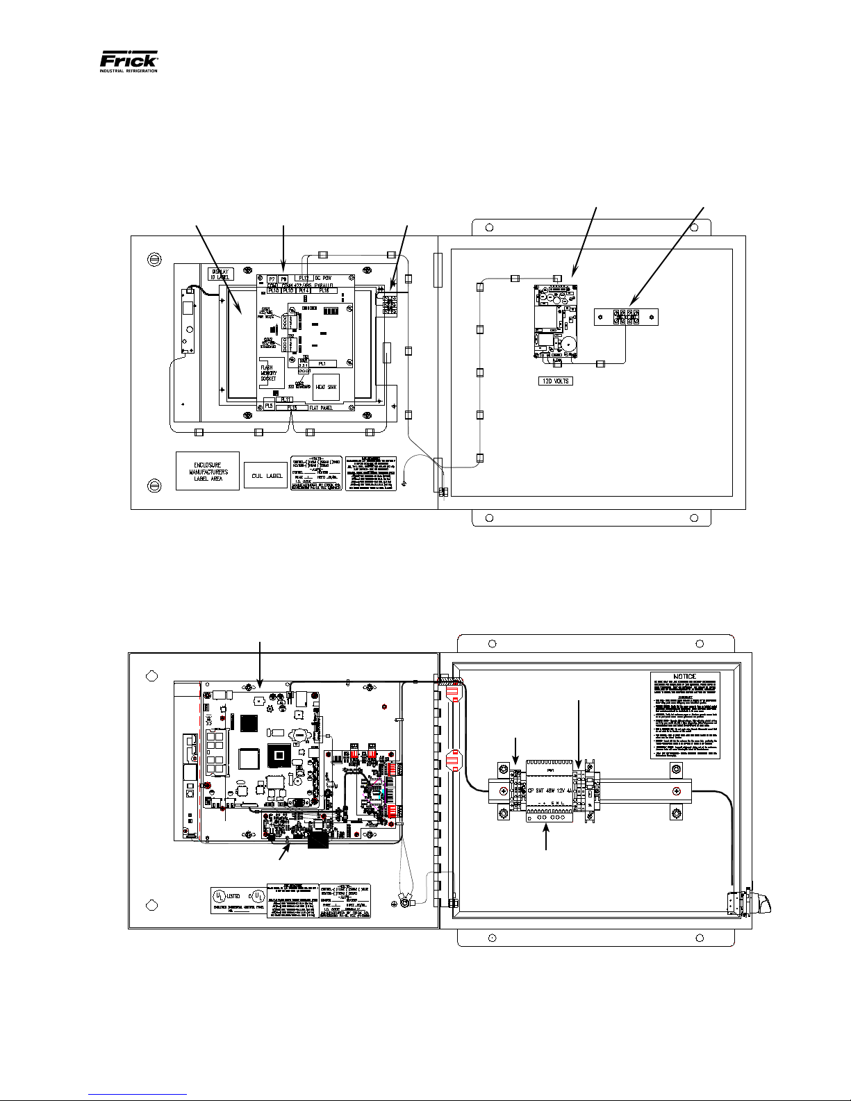
QUANTUM™ LX EVAPORATOR CONTROL PANEL
Power Supply
Communications
120 VAC Power
Rear of Display
Quantum™ LX
MAINTENANCE
090.610-M (MAY 2016)
Page 7
The inside of the panel will vary, depending on whether it is a Q4 or Q5 based controller. The following pictorial shows both versions:
Q4 Controller
Controller
Connection
Terminal Block
Q4 Panel
Q5 Controller
120 VAC Power
Connection
Communications
Terminals
Interface Board
Q5 Panel
Power Supply
Page 8

090.610-M (MAY 2016)
Page 8
QUANTUM™ LX EVAPORATOR CONTROL PANEL
MAINTENANCE
NOTES:
Page 9

QUANTUM™ LX EVAPORATOR CONTROL PANEL
MAINTENANCE
SECTION 2
REMOTE PANEL
090.610-M (MAY 2016)
Page 9
Page 10
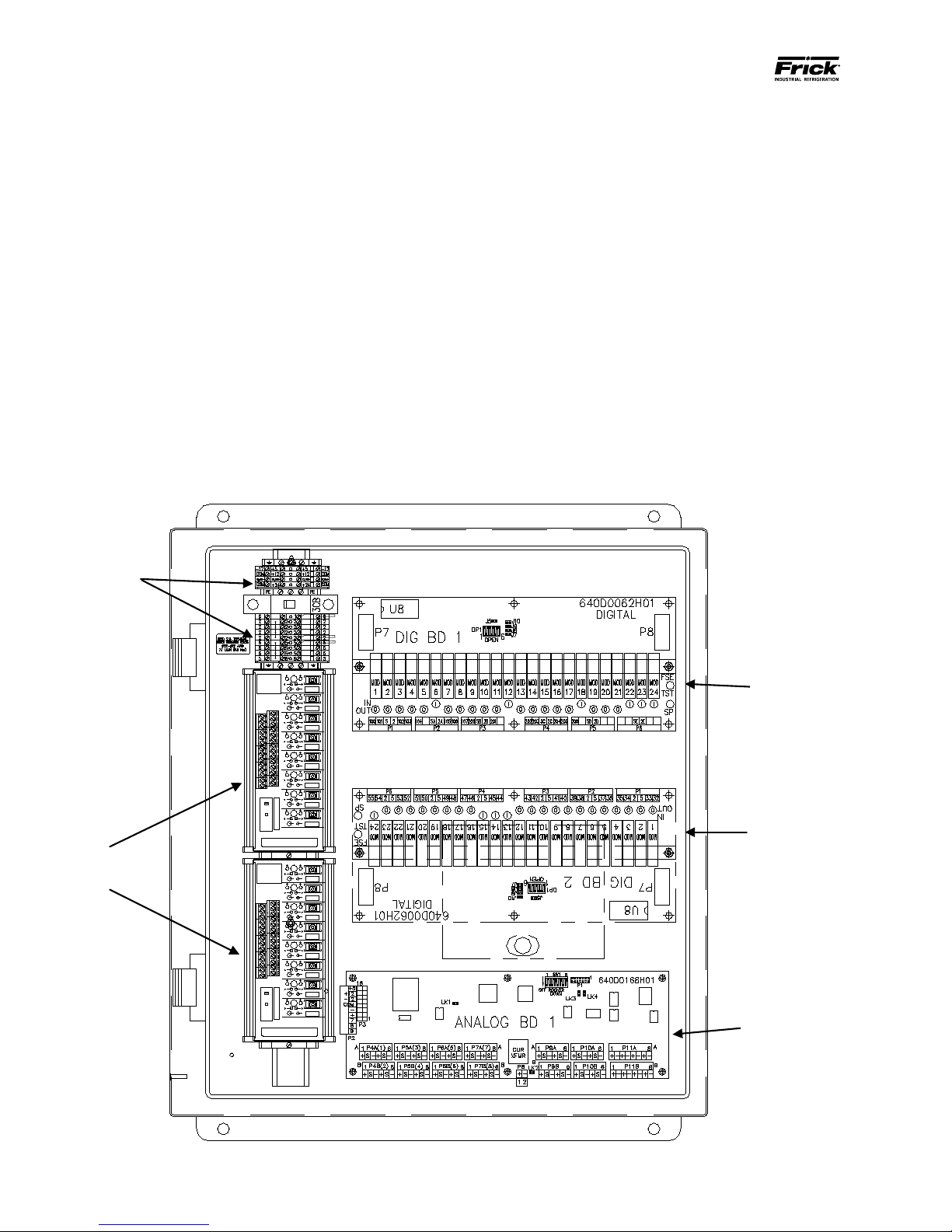
090.610-M (MAY 2016)
Field and panel
wiring
HOA
Modules
Analog
Board
Digital
Board
Optional
Digital Board
Page 10
QUANTUM™ LX EVAPORATOR CONTROL PANEL
MAINTENANCE
THE EVAPORATOR REMOTE PANEL ENCLOSURE
DESCRIPTION
Both versions of the Evaporator control panel, Q4 and
Q5, utilize the same Remote panel. With the Quantum™
LX Evaporator system version 3.0x and later, a single
Quantum ™ Control Panel can control up to ten remote
panels with each remote capable of handling three
Evaporator units, for a total possible of thirty units. It is
also capable of Ethernet access, which can be viewed
remotely through any web browser, or the optional
®
Frick
Evaporator Operator Interface Panel.
The Frick® Quantum™ LX Remote panel enclosure
utilizes available space efciently. The panel is also
equipped with the necessary posts and hardware to
add options in the eld. Each Remote panel is congured with one Digital and one Analog board, and a
second Analog board may be present depending upon
installed options.
There are additionally two HOA (Hands Off Automatic)
boards installed, which allow for overriding the automatic function of the control by allowing the user to
manually operate outputs.
The DC power/communications harness in this panel
is color-coded. This will make wire identication much
easier. The coding is as follows:
• +5VDC - RED
• +12VDC - YELLOW
• -12VDC - PURPLE
• Common/Ground - BLACK
• +RX/TX - BLUE
• -RX/TX - BLUE w/WHITE stripe
Page 11

QUANTUM™ LX EVAPORATOR CONTROL PANEL
Power
AC Input
DC
Output
-12 RET RET +5 +5 +12
MAINTENANCE
POWER SUPPLY FOR THE REMOTE PANEL
090.610-M (MAY 2016)
Page 11
DESCRIPTION
CAUTION! Measuring the power supply voltages
require the control power to be energized. Extreme
care must be observed when taking any readings, as
120 VAC is present within the power supply.
The Remote panel power supply is mounted on the
inside at the top of the panel, as shown at the bottom
of this page. A three-pin connector provides 120 VAC
power to the supply, and a six-pin connector delivers
DC power out of the supply. These connections are of
a push-on multiple contact connector type. This power
supply is not adjustable.
EVAPORATOR REMOTE PANEL POWER
The Evaporator Remote Panel utilizes the +5 VDC, +12
VDC and – 12 VDC voltages from its power supply. To
perform measurements on the power supply voltages,
use a reliable, calibrated Digital Volt Meter (DVM). The
DVM should be accurate to 1/100 of a volt DC. Turn the
control power switch to ON.
Measure the voltages on the power supply at the DC
output connector as shown below.
Power supply is located at the inside top of the Remote Panel
Page 12

090.610-M (MAY 2016)
Page 12
QUANTUM™ LX EVAPORATOR CONTROL PANEL
MAINTENANCE
Page 13
QUANTUM™ LX EVAPORATOR CONTROL PANEL
MAINTENANCE
SECTION 3
Q5 CONTROLLER
090.610-M (MAY 2016)
Page 13
Page 14
090.610-M (MAY 2016)
Page 14
QUANTUM™ LX EVAPORATOR CONTROL PANEL
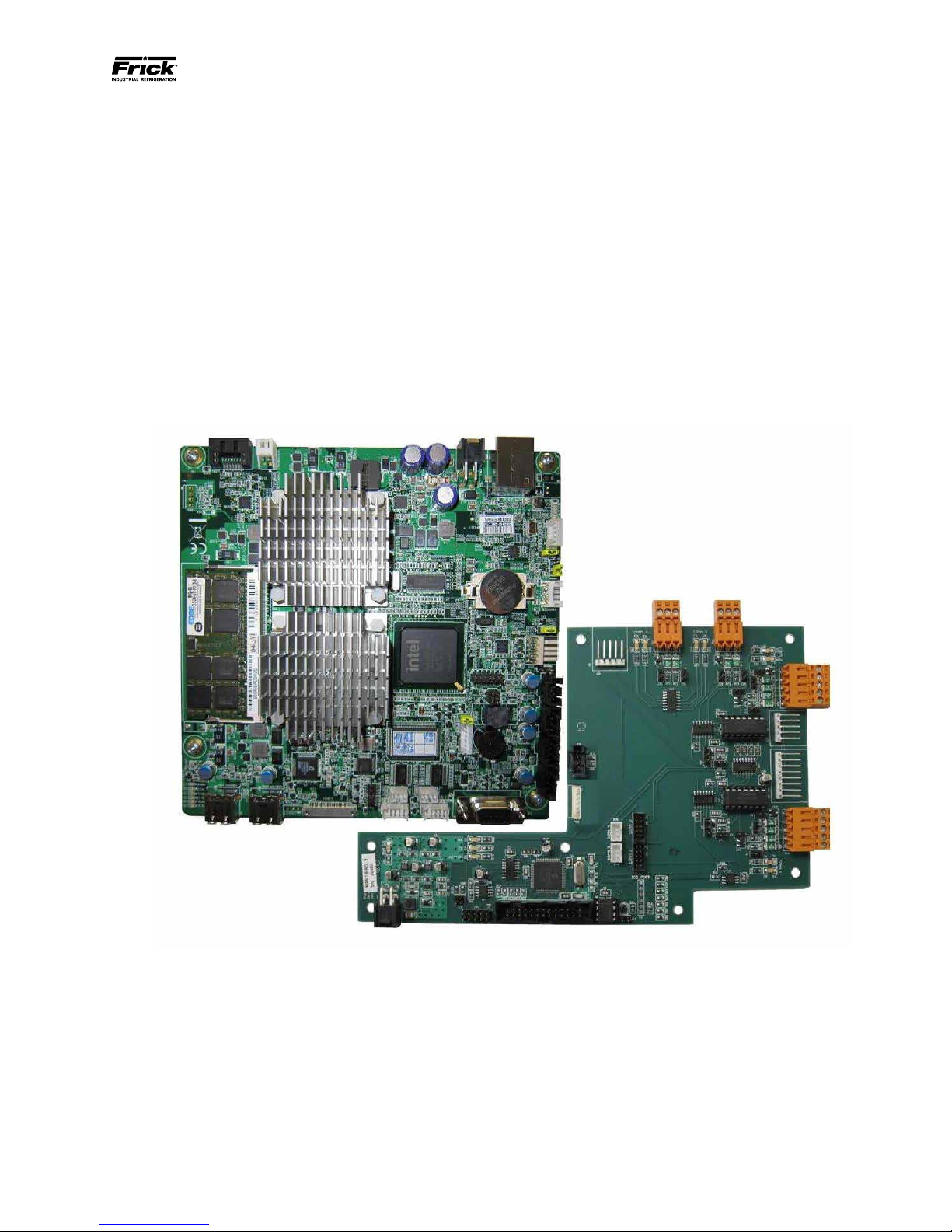
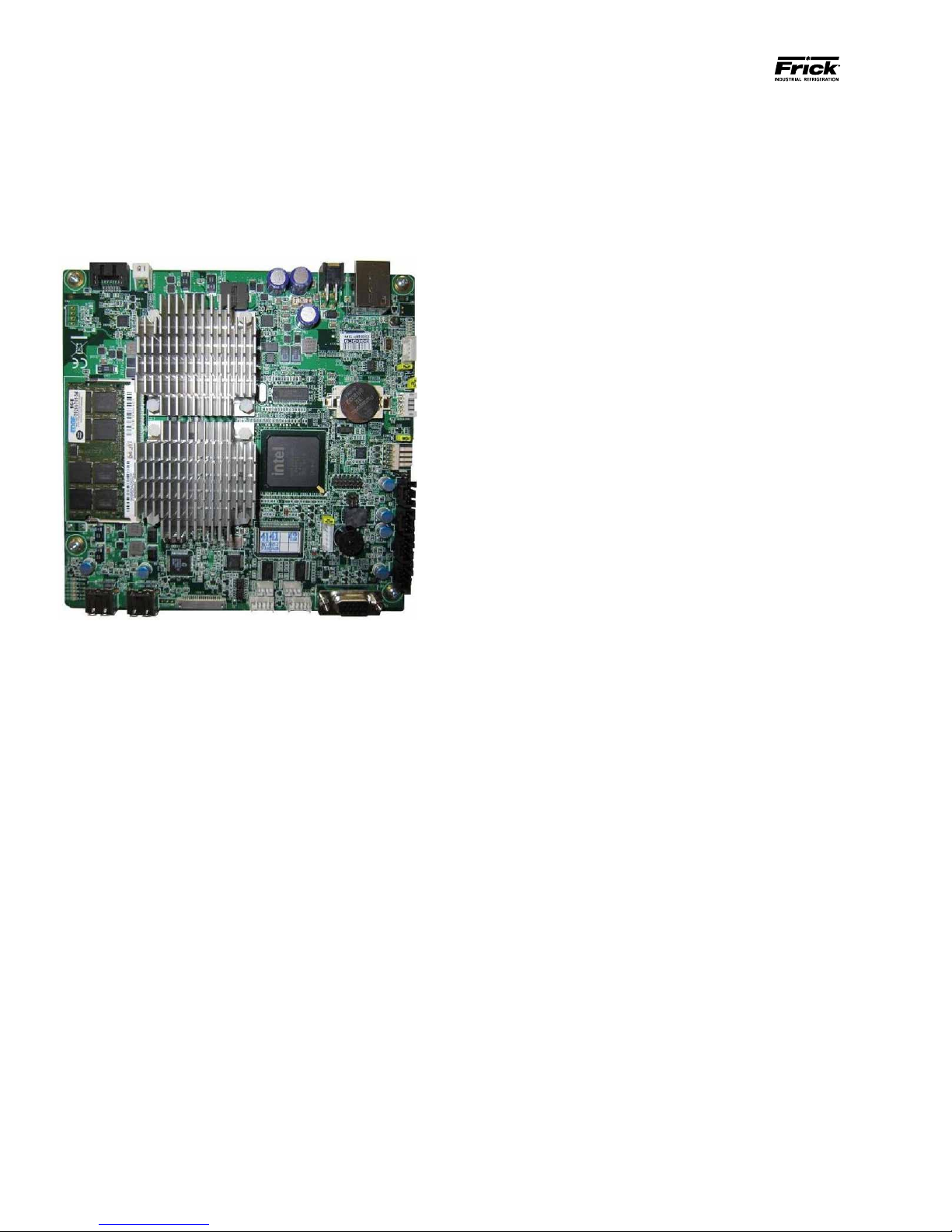
Q5 CONTROLLER BOARD
INTRODUCTION
Frick® Controls has released the latest version of the
Quantum ™ LX microprocessor board. This brand will
be referred to as the Q5. A photo of this board appears
here:
MAINTENANCE
• Just before fully booting, a Loading bar will
appear at the bottom of the screen, showing
the percent of load that has completed.
• The Operating Status screen will appear.
After the Q5 has properly powered up, the following
sequence of events is indicative of proper communication to the analog and digital boards:
• The Analog and Digital I/O boards TX/RX lights
should be blinking.
• Each I/O board should have the power LED
lighted and the Active LED should be blinking.
• The rst thing that should be checked when
troubleshooting the Q5 board is its powering
up sequence.
FEATURES
The Q5 board includes the following features:
• 6 total USB ports (2 are dedicated, 4 are available)
• 10/100/1000 Mbps Ethernet Connection
• 2 RS-422 ports
• 2 RS-485 ports
• External Video monitor connection
• LED indicators to verify proper operation of
various on board areas (power, communications, Ethernet connectivity, etc.)
• 2 GB RAM memory
• Battery to maintain date and time
WHAT SHOULD OCCUR WHEN APPLYING POWER
When powering up, the following sequence of events
are indicative of a properly working main processor
board:
• The six LED’s in the lower left corner should
turn on solid.
WHAT IF THE OPERATING STATUS SCREEN IS NOT
SHOWN
If the Operating Status screen is not shown, check the
following items:
1. If no LED’s are lit, then check AC and DC power. Refer to the Power Supply section.
2. Check if the lighting of the LED’s is occurring
as described in the What Should Occur When
Applying Powering section.
• If the powering up sequence continues to repeat without displaying the
Operating Status screen, then there
is a booting problem.
3. Check all plugged connectors for proper seating.
4. Check if an error message is displayed when
booting.
• Be sure to write down any error
messages exactly as they appear,
as well as the top line on the screen
where the message appears.
5. Check that the software is OK:
• Is the correct software installed?
• The on-board “buzzer” should “beep” once.
• The display should show several DOS (text)
style screens. A penguin image will appear
in the upper left corner of the screen as the
boot sequence progresses.
• Did you just install new software?
Page 15
QUANTUM™ LX EVAPORATOR CONTROL PANEL
MAINTENANCE
090.610-M (MAY 2016)
Page 15
6. Check the display. If the Q5 board is booting
but you have no display, check the following:
• Check the backlight tube. Look very
closely at the display to see if anything is visible in the dark screen.
Using a beam type source of good
lighting, such as a ashlight, look for
any ghost type image. If it appears
that there is something on the screen
but very dark, the problem may be
with the backlight tube. There is
a sticker on the display mounting
plate, that will have a part number
that describes the type of display. If
there is no sticker, you must take the
display apart to identify the display
manufacturer.
• Verify that both the display cable and
the inverter cable are rmly seated.
It may be necessary to remove the
video cable from the back of the display and re-seat it to be sure it is
connected properly. Note: This is a
small connector and caution should
be observed so that it is not damaged due to excessive force.
To replace the battery, ensure that the Control Power
switch has been turned OFF.
Locate the Battery socket, as shown on the following
drawing:
Place your ngernail under the edge of the battery, and
gently lift up. The battery should release itself from the
socket easily. Take a new battery and place it into the
holder in the same orientation as the old battery (the
side with the writing must be facing out). Return the
Control Power switch back to ON.
Once the Q5 has rebooted, the correct Date and Time
must be set.
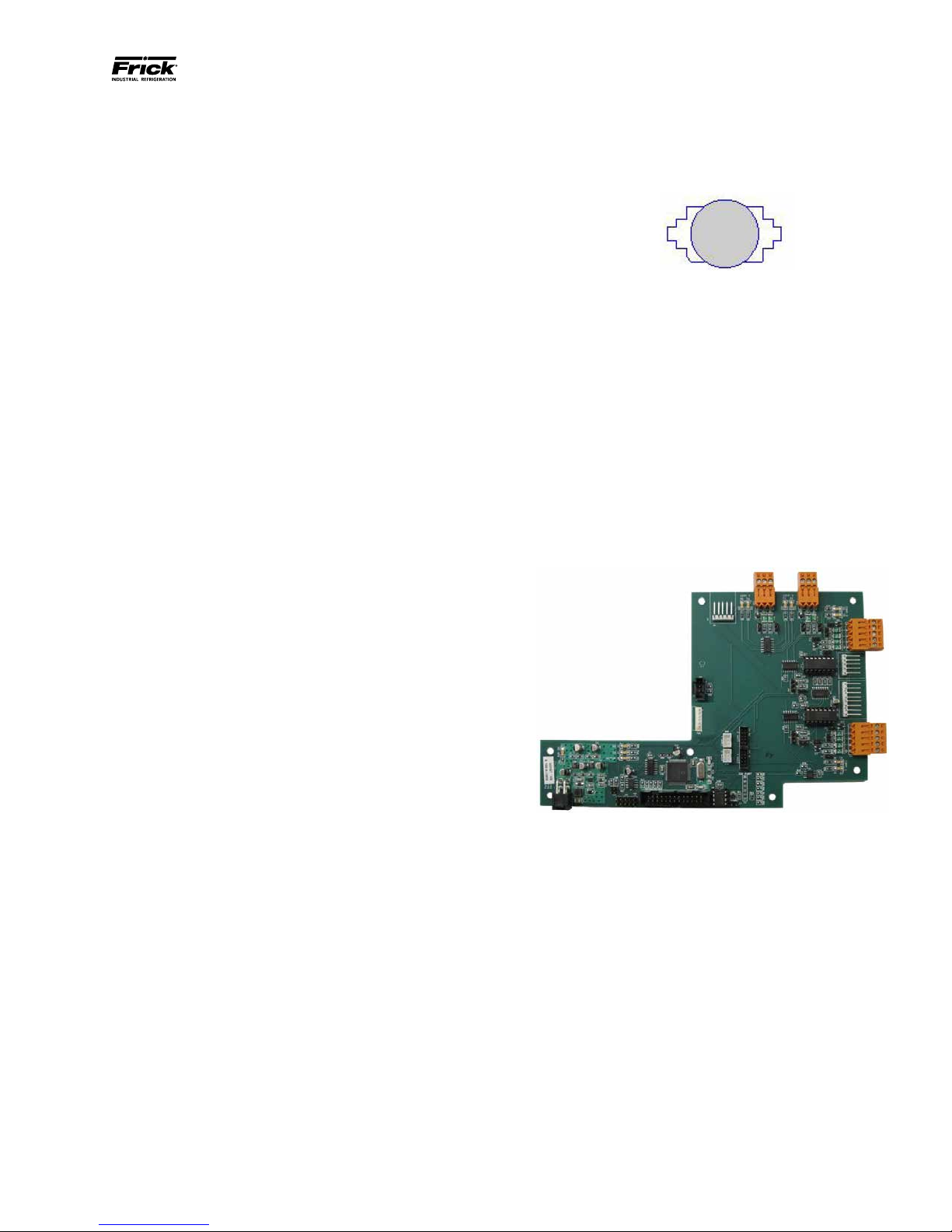
Q5 INTERFACE BOARD
An interface board has been developed by Frick controls allowing the user to interface exterior connections to the Q5. A photo of this interface board is
shown here:
• Refer to the Operator Interface section and check that the display, display cable, and software versions are
matched correctly.
BATTERY FUNCTION AND REPLACEMENT
The Q5 board utilizes a battery to maintain correct date
and time for the purpose of stamping warnings and
shutdowns with the date and time that they occurred.
If the date and time are not being maintained properly,
this may indicate that the battery is not functioning,
and should be replaced. The battery may be ordered
through Baltimore Parts (P/N 333Q0001786) or may be
purchased at most electronic shops (manufacturers P/N
CR-2032).
The battery is fully assessable, but is surrounded by
sensitive electronic components, so care should be
taken when changing.
Page 16
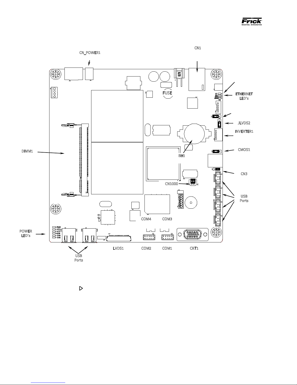
090.610-M (MAY 2016)
JLVDS2
POWER
LVDS1
CRT1
COM1
COM2
FUSE
DIMM1
CN_POWER1
USB
ETHERNET
CMOS1
Flash Card located
Page 16
QUANTUM™ LX EVAPORATOR CONTROL PANEL
Power Connector
MAINTENANCE
Q5 BOARD
BH1
Battery
CN1
Ethernet
Connector
under the board
here
LED’s
JLVDS3
(See Note 4
below)
JLVDS3
INVERTER1
Inverter
Connector
CN3
CN1000
Ports
LED’s
USB
Ports
NOTE 1: The triangle symbol ( )
COM4
RS-485
Video Connector
RS-232
denotes Pin 1 on connectors. Refer to the chart on the following page for jumper settings.
COM3
RS-485
RS-232
Video Monitor
NOTE 2: Do NOT remove the CN4 jumper. Removal of this jumper will cause the processor to not power up.
NOTE 3: Although the Q5 board is the main controller, most of customer connections will be to the Interface board, as
shown later.
NOTE 4: Ensure that this jumper is installed between pins 1 and 2 if a display is used that requires an inverter board. Install
the jumper between pins 2 and 3 for an LED display that does not use an inverter board. See also the jumper table on the
next page for JLVDS3.
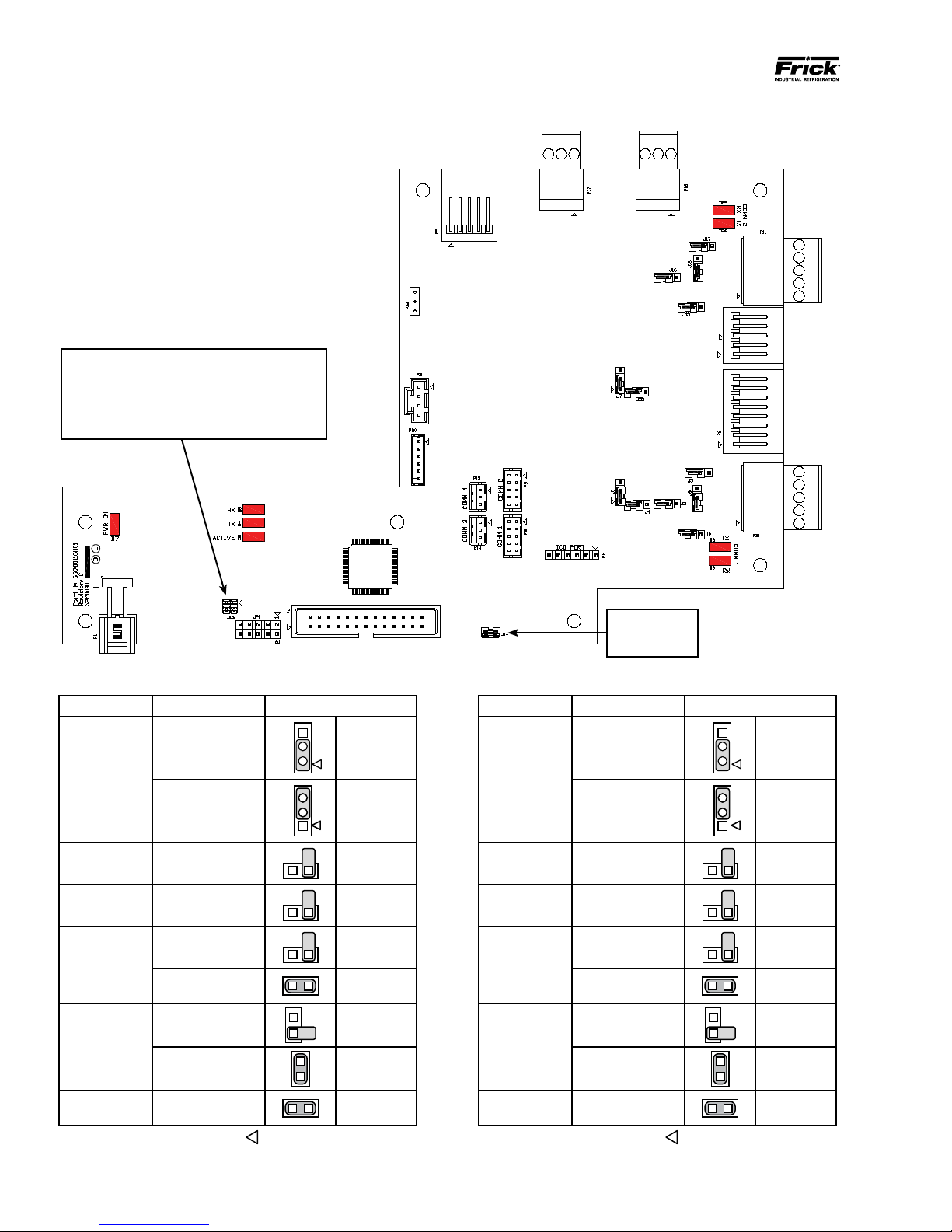
Page 17
QUANTUM™ LX EVAPORATOR CONTROL PANEL
1 2 3
1 2 3
1 2 3
2
1
1
2
3
2
5
1
1
2
1
1 2 3
2
1
1 2 3
MAINTENANCE
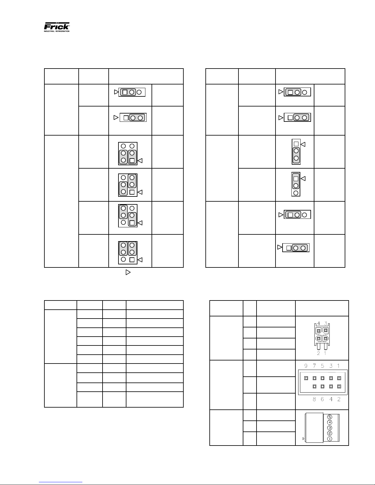
Q5 BOARD JUMPERS, LED’S AND CONNECTORS
JUMPER TABLE
090.610-M (MAY 2016)
Page 17
Jumper
Title
CMOS1
(CMOS
Clear)
CN1000
(LCD
Resolution
Selector)
Function Jumper Setting
Normal
(default)
Closed
Clear
CMOS
24-bit
800x600
24-bit
1024x768
18-bit
800x600
18-bit
640x480
(default)
1 2 3
6
4
6
4
6
4
2
6
4
Closed
1-3 Closed
5
3
2-4 Closed JLVDS2
3-5 Closed
3
2-4 Closed
5
1-3 Closed
3
4-6 Closed JLVDS3
3-5 Closed
5
3
4-6 Closed
1 - 2
2 - 3
&
&
&
&
Jumper
Title
CN3
(Touch
Panel Type
Selector)
(Backlight
Level Se-
lector)
(Backlight
Control
Mode)
Function Jumper Setting
5-Wire
Touch
Screen
8-Wire
Touch
Screen
(default)
0 – 5V
(default)
0 – 2.5V
3
Voltage
Mode - use
with inverter
(default)
PWM Mode
(Use for LED
display - no
inverter)
1-2 Closed
2-3 Closed
2-3 Closed
1-2 Closed
1-2 Closed
2-3 Closed
NOTE 1: The triangle symbol (
NOTE 2: Jumper CN4 is not shown on this chart, as it must always be installed.
LED DEFINITION TABLE
LED Title Label Color Function
LED1 Red 5VSB
LED2 Red 3VSB
Power
LED’s
LED3 Green VCC 12V
LED4 Green VCC 5V
LED5 Green VCC 3V
LED6 Blue Power On OK Status
1000MB Green Giga – LAN Speed
CN1000
(LCD
Resolution
Selector)
100MB Yellow 100MB - LAN Speed
10MB Red 10MB –LAN Speed
ACT
Green
(Blinks)
) denotes Pin 1 on connectors.
LINK Activity
CONNECTOR PINOUT TABLE
Connector
Pin Function
Title
1 Ground (GND)
CN_PWR1
2 Ground (GND)
(Power
Input)
3 VCC 12V
4 VCC 5V
COM1 &
2 Receive (RX)
COM2
(RS-232
3 Transmit (TX)
Communi-
cations)
COM3 &
5 Ground (GND)
1 -RX/TX
COM4
(RS-485
Communi-
cations)
2 +RX/TX
3 Ground (GND)
Page 18
090.610-M (MAY 2016)
2
1
2
1
Page 18
Baud Rate Jumpers
J15 Not Installed = 19200 (Default)
J15 Pins 1-2 Installed = 38400
J15 Pins 3-4 Installed = 56K
J15 Pins 1-2 and 3-4 Installed = 115K
QUANTUM™ LX EVAPORATOR CONTROL PANEL
MAINTENANCE
Q5 INTERFACE BOARD
COMM
4
COMM
3
COMM
2
COMM
1
COMM 1 JUMPER SETTINGS COMM 2 JUMPER SETTINGS
Jumper Title Function Jumper Setting
3
RS-422 (4-Wire)
Default
J1
RS-485
(2-Wire)
J2
J3
Pull Down
Default
Pull Up
Default
RS-422
J5
Default
RS-485
RS-422
Default
J6
RS-485 1 - 2 Closed
3
2
1
1 - 2 Closed
2 - 3 Closed
1 Pin Only
1 Pin Only
1 Pin Only
1 - 2 Closed
1 Pin Only
Do Not
Remove J14
Jumper Title Function Jumper Setting
3
3
2
1
1 - 2 Closed
2 - 3 Closed
1 Pin Only
1 Pin Only
1 Pin Only
1 - 2 Closed
1 Pin Only
J7
J13
J16
J17
J18
RS-422 (4-Wire)
Default
RS-485
(2-Wire)
Pull Down
Default
Pull Up
Default
RS-422
Default
RS-485
RS-422
Default
RS-485 1 - 2 Closed
J4
High Speed Target
Default
NOTE: The triangle symbol ( ) denotes Pin 1 on connectors.
1 - 2 Closed
J22
High Speed Target
Default
1 - 2 Closed
NOTE: The triangle symbol ( ) denotes Pin 1 on connectors.
Page 19
QUANTUM™ LX EVAPORATOR CONTROL PANEL
090.610-M (MAY 2016)
MAINTENANCE
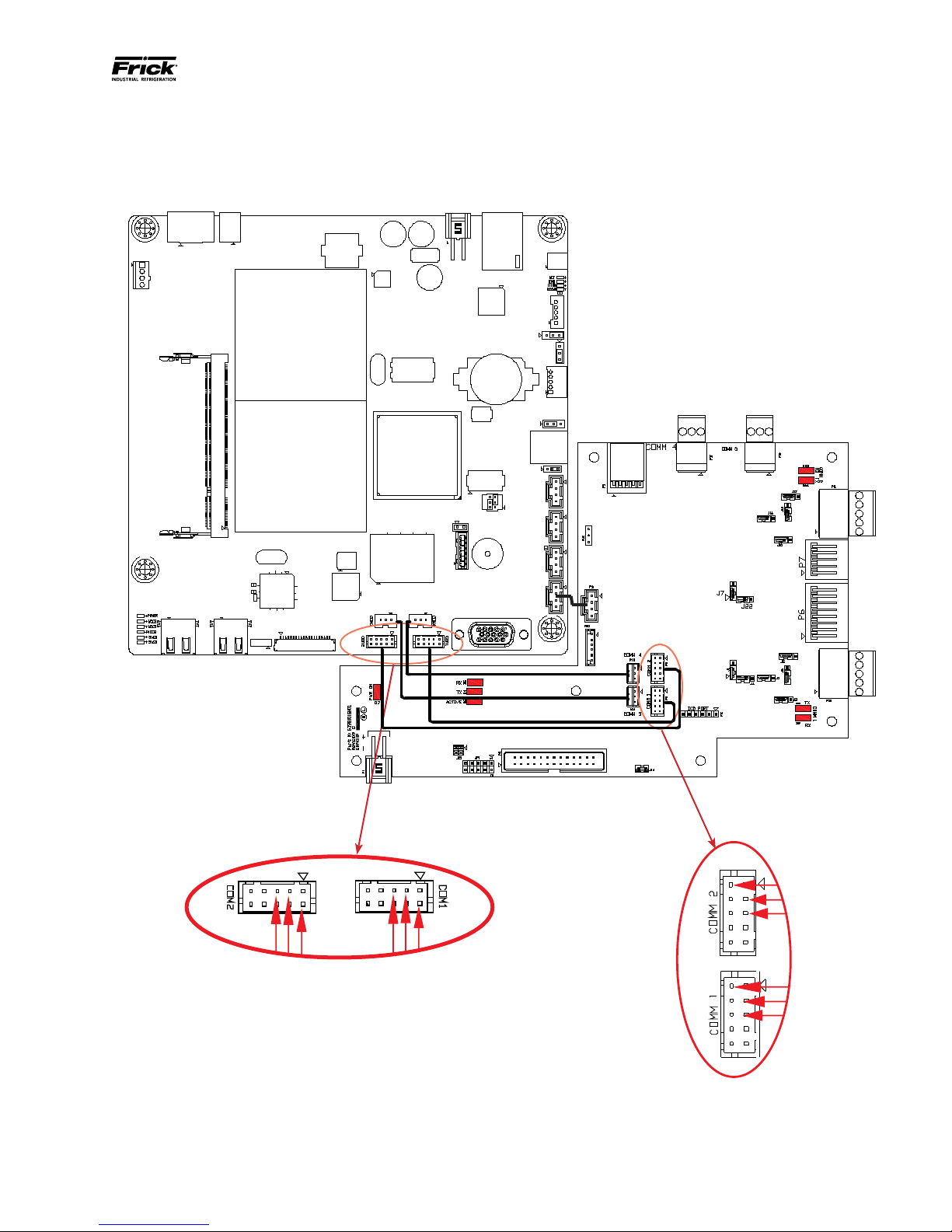
Q5 INTERCONNECTIONS
The pictorial below depicts the Q5 motherboard, and the necessary interconnects between it and the Interface
Page 19
If the harness for either
COMM1 or COMM2 is
ever removed for either
repair, replacement or
troubleshooting, ensure
that the pinout matches
as shown here when
plugging the ends back
in. All other Interconnec
tion harness ends share
the same pinout at both
ends.
-
Page 20
090.610-M (MAY 2016)
Page 20
QUANTUM™ LX EVAPORATOR CONTROL PANEL
MAINTENANCE
POWER SUPPLY (Q5)
DESCRIPTION
The power supply of the Q5 control panel consists a
single, 12 volt DC supply, and is located on the DIN rail
at the back of the enclosure.
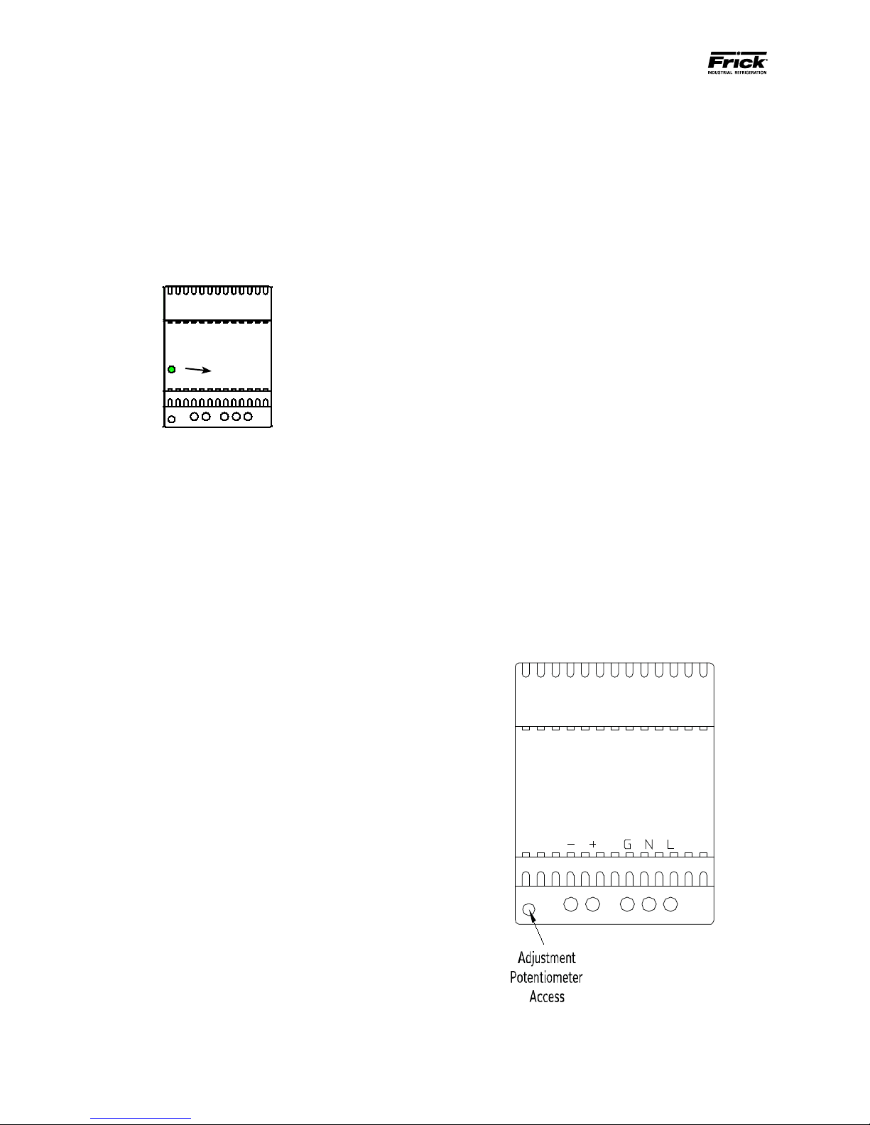
The supply is adjustable and has an indicator to show
that it is powered. Refer to the following page for the
location for the adjustment.
Power ON
Indicator
12 Volt DCPower Supply
POWER DISTRIBUTION
12 Volt DC Power is distributed to the Q5 processor
board and Interface Board.
MEASURING VOLTAGES
CAUTION! Measuring and adjusting the power supply
voltage requires the control power switch to be energized. Extreme care must be observed when taking any
readings, as 120 or 230 VAC (depending on incoming
system voltage) will be present next to the DC voltage connector. Adjusting the supply requires the use
of a small Philips screwdriver inserted into the supply
to access an adjusting potentiometer. CAUTION: It is
possible for the screwdriver (and the person making the adjustment) to come into contact with potentially lethal voltages. Proper Personal Protective
Equipment (PPE) measures need to be observed.
• LED’s on the Q5 are lit, but nothing appears on
the display.
To perform measurements and adjustments on the
power supply voltage, use a reliable, calibrated Digital Volt Meter (DVM). The DVM should be accurate
to 1/100 of a volt DC. With the control power switch
turned ON, wait until the Operating Screen appears.
This is because the graphics required to create this
screen will draw more current than when the screen is
showing the normal POST (DOS) style messages during
a boot up. If the screen never appears however (possibly due to a voltage problem), you will need to proceed
regardless of what is or is not displayed.
In order to properly measure the DC power system, it
must be checked at the DC power supply.
ADJUSTMENT
Ensure that the meter is set to the proper range (DC,
0-50 V or equivalent), as well as observing proper wire
polarity. The power supply drawing shown on the following page applies to all three power supplies. The
adjustment access hole for each supply is located on
the lower left of the front of the supplies. If an adjustment is required, use a thin, Philips screwdriver, insert
the tip into the access hole for the appropriate voltage
potentiometer (refer to the diagram on the following
page for adjustment location). NOTE: Extreme care
must be used when adjusting the potentiometer.
Adjustment should only be performed by qualied
personnel. The use of a non-conductive device is
recommended.
All circuit boards within the Q5 control panel require
accurately adjusted DC voltages in order to function
properly. Periodic measurement and adjustment of the
DC power system is recommended for optimum system operation. Over time, it is possible for temperature, humidity, vibration and component age, to degrade the accuracy of these voltages. When any of the
DC voltages begin to stray from their optimum range,
mysterious problems can begin to arise.
Even with a perfectly adjusted supply, it is possible for
a potential drop in voltage at each connection point.
This drop normally is in the millivolt range, but under some conditions, the drop can be much greater (as
high as tenths of a volt). Some examples of problems
could be:
• Loss of or intermittent communications failures.
• Q5 reboots for no apparent reason.
+ -DCG N L
120 VAC
or
240 VAC
Page 21

QUANTUM™ LX EVAPORATOR CONTROL PANEL
+12 VDC Adjustment
Locate the DC power supply terminals. Place the
negative lead on - and the positive lead on +.
Verify that the DVM is displaying in the range of
+12.10 to +12.20.
If adjustment is required, locate the adjustment
access hole on the +12 VDC supply, as previously
shown. While watching the DVM, slowly rotate
the screwdriver blade clockwise to increase the
voltage or counter-clockwise to decrease until the
voltage is correctly adjusted.
POWER SUPPLY REPLACEMENT
If the power supply is found to be bad, or not capable
of acceptable adjustment, the failing supply will need
replacing. Refer to the Recommended Spare Parts list
for the appropriate part number.
MAINTENANCE
090.610-M (MAY 2016)
Page 21
Page 22

090.610-M (MAY 2016)
Page 22
QUANTUM™ LX EVAPORATOR CONTROL PANEL
MAINTENANCE
Page 23

QUANTUM™ LX EVAPORATOR CONTROL PANEL
MAINTENANCE
SECTION 4
Q4 CONTROLLER
090.610-M (MAY 2016)
Page 23
Page 24

090.610-M (MAY 2016)
Page 24
QUANTUM™ LX EVAPORATOR CONTROL PANEL
MAINTENANCE
Q4 CONTROLLER BOARD
INTRODUCTION
Frick® Controls has strived to remain on the cutting
edge of microprocessor technology and development.
Because of the ever-increasing speed, memory features, and power of microprocessors, Frick® will continue to introduce the latest advancement in microprocessor control technology.
• The display should show several DOS (text)
style screens. A penguin image will appear
in the upper left corner of the screen as the
boot sequence progresses.
• Just before fully booting, a Loading bar will
appear at the bottom of the screen, showing
the percent of load that has completed.
• The Operating Status screen will appear.
After the Q4 has properly powered up, the following
sequence of events is indicative of proper communication to the analog and digital boards:
• The Analog and Digital I/O boards TX/RX
lights should be blinking.
• Each I/O board should have the power LED
lighted and the Active LED should be blinking.
WHAT IF THE OPERATING STATUS SCREEN IS NOT
SHOWN
If the Operating Status screen is not shown, check the
following items:
Q4 Board
WHAT SHOULD OCCUR WHEN APPLYING POWER
The rst thing that should be checked when troubleshooting the Q4 board is it’s powering up sequence.
When powering up the Q4, the following sequence of
events are indicative of a properly working main processor board:
• Green PWR (Power) LED will turn on solid.
• Red FLASH LED will ash several times early
in the boot sequence. It is normally not lit.
• LED D8 (on the smaller board) will start to
blink at the rate of about once-per-second. It
will continue to blink after the Q4 has booted.
The only time that this ashing rate is interrupted, is when a key is pressed on the keypad.
1. If no LED’s are lit, then check AC and DC power. Refer to the Power Supply section.
2. Check if the lighting of the LED’s is occurring
as described in the What Should Occur When
Applying Powering section.
• If the powering up sequence continues
to repeat without displaying the Operating Status screen, then there is a booting
problem.
3. Check for bad connections.
4. Check if an error message is displayed when
booting.
• Be sure to write down any error mes-
sages exactly as they appear.
5. Check that the software is OK:
• Is the correct software installed?
• Did you just install new software?
6. Remove Flashcard and reboot. This will cause
the Q4 to boot under a pre-LX operating
software. If it boots properly under this older
software, then trying re-booting from the
Flashcard again. If it doesn’t boot with the
card, then the Flashcard could be corrupted,
and needs to be replaced.
Page 25

QUANTUM™ LX EVAPORATOR CONTROL PANEL
Battery Release
MAINTENANCE
090.610-M (MAY 2016)
Page 25
7. Check the display. If the Q4 board is booting but
you have no display, check the following:
• Check the backlight tube. Look very closely
at the display to see if anything is visible in
the dark screen. Using a beam type source of
good lighting, such as a ashlight, look for any
ghost type image. If it appears that there is
something on the screen but very dark, the
problem may be with the backlight tube. On
the LG Philips, NEC and Sharp displays this
tube is eld replaceable. On the Samsung display it is not available and the display will have
to be replaced. There may be a sticker on the
display mounting plate. If there is, it will have
a part number that describes the type of display. If there is no sticker, you must take the
display apart to identify the display manufacturer.
• Verify that both the display cable and the in-
verter cable are rmly seated. These cables
both originate from the same connector on
the Q4. It may be necessary to remove the
video cable from the back of the display and
re-seat it to be sure it is connected properly.
Note: This is a small connector and caution
should be observed so that it is not damaged
due to excessive force.
BATTERY FUNCTION AND REPLACEMENT
The Q4 board utilizes a battery to maintain correct
date and time for the purpose of stamping warnings
and shutdowns with the date and time that they occurred. If the date and time are not being maintained
properly, it may indicate that the battery is not functioning, and should be replaced. The battery may be
ordered through Baltimore Parts (P/N 333Q0001786) or
may be purchased at most electronic shops (manufacturers P/N CR-2032).
The battery is partially covered by the communications
daughter board, and is located directly beneath the
COM1 port (it may be necessary to unplug any connector that is plugged into COM1 to fully access the
battery).
To replace the battery, ensure that the Control Power
switch has been turned OFF.
Locate the Battery Release Clip on the following drawing:
Clip
• Refer to the Operator Interface section and
check that the display, display cable, and software versions are matched correctly.
Battery
Battery
Holder
Simply push the clip away from the battery, to release
the battery from the holder. Remove the battery, observing the orientation. Take a new battery and place
it into the holder in the same orientation as the old
battery (the side with the writing must be facing out).
Reinstall the COM1 plug (if removed), and return the
Control Power switch back to ON.
Once the Q4 has rebooted, the correct Date and Time
must be set.
Page 26

090.610-M (MAY 2016)
Page 26
RS-422/485
RS-422/485
USB Connector
(Depending on board version,
USB could be located in either
of these two locations.
COM-3
(PL6)
RS-232
connector
COM-1
(TB1)
LK2
PL1
RS-422/485
connector
PL2
3.3 Volt
Battery
PL3
COM-2
COM-2
(TB2)
(TB2)
connector
connector
PL5
PL7
LK1
PL
Flash Card Socket
(located under
board)
LK4
A
LK3
QUANTUM™ LX EVAPORATOR CONTROL PANEL
MAINTENANCE
Q4 BOARD
+5VDC
Power
PL
9
PL8
COM-1
4
3
2
1
TB1
A
B
LK
TB2
7
LK
LK
5
4
6
3
2
1
COM-2
COM-2
PL
B
11
PL
12
PL10 PL6
RS-
422
LK2
RS-
422
LK1
TB3
LK
10
LK
LK
LK
LK
LK
RET / GND
+12VDC
PL13
PL14
COM1
(TX)
COM1
(RX)
9
8
A B
7
COM2
(TX)
LK
6
LK
5
A
4
3
RS-232
2
3
PL
15
-RX/-TX (I/O Boards)
+RX/+TX (I/O Boards)
PL
17
PL
18
LK9
LK8
POR
T
80H
D4 D5 D7
D3
D2
LK16
D1
B
LK17
1
Baltimore Parts with LK4
set to B position for an
4
1
3
2
0
D11
D1
D9
0
COM2
(RX)
B A
KB
This assembly is
shipped from
LG Philips Display.
If using a Samsung,
NEC or Sharp
Display, set LK4
to position A.
LX panels use
the Sharp display.
PL
19
PL
24
LK12
P
PL16
5
6
7
ON
D13
D1
8
2
7
SW1
6
LK11
W
SU
FL
SP
AS
H
PL2
D6
LK11
PL4
D8
PL
PL1
3
Keypad
Cable
Communications Board
(small top board)
COM-2
(TB3)
RS-232
connector
Display
Cable
CAT-5 Ethernet
NOTE: There are duplicate numbers for the links on the processor (larger) board and the communications (smaller)
board. If you must make a change to a jumper (link), ensure that you modify the correct link.
Processor Board
(large botom board)
Controller Board Pictorial
Page 27

Processor Board Jumpers
2 second Watchdog timer timeout
LK1
LK2
LK3
LK4
LK5
LK6
LK7
LK8
LK9
LK10
LK11
LK12
* Standard Setting
in
8 second Watchdog timer timeout
out*
Watchdog timer Enabled
in*
Watchdog timer Disabled
out
+5V Backlight Voltage (not used)
A
+12V Backlight Voltage (all displays)
B *
+5V Supply (Samsung, NEC, Sharp)
A
+3.3V Supply (LG Philips & Sharp LED Display)
B *
COM4 IRQ3
A
COM4 IRQ10
B *
COM3 IRQ4
A
COM3 IRQ11
B *
Battery Backup Enabled
A *
Battery Backup Disabled (CMOS Cleared)
B
RS-485 Receiver Enabled
in*
RS-485 Receiver Disabled
out
RS-485 Terminated
in*
RS-485 Not Terminated
out
RS-422 Terminated
in
RS-422 Not Terminated
out*
Bit 1 of 259H “Logic 1” User Application Link
in*
Bit 1 of 259H “Logic 0” User Application Link
out
Bit 2 of 259H “Logic 1” User Application Link
in*
Bit 2 of 259H “Logic 0” User Application Link
out
QUANTUM™ LX EVAPORATOR CONTROL PANEL
MAINTENANCE
Q4 BOARD SETTINGS
090.610-M (MAY 2016)
Page 27
Communications Board Jumpers
Com-1 (TB1)
in
LK2
LK7
LK8
LK9
LK10
LK16
* Standard Setting
Terminate COM1
out*
No termination
in
Pull down COM1
out*
No pull down
in
Pull up COM1
out*
No pull up
in
Pull down COM1
out*
No pull down
in
Pull up COM1
out*
No pull up
AB*COM1 RS-422 (TB1)
COM1 RS-485 (TB1)
Com-2 (TB2 - TB3)
LK1 in
LK3 in
LK4 in
LK5 in
LK6 in
LK11 A
LK17 A
* Standard Setting
Terminate COM2
out*
No termination
Pull down COM2
out*
No pull down
Pull up COM2
out*
No pull up
Pull down COM2
out*
No pull down
Pull up COM2
out*
No pull up
Select RS-232 for COM2 (TB2)
B*
Select RS-422/RS-485 for COM2 (TB3)
COM2 RS-422 (TB2)
B*
COM2 RS-485 (TB2)
RS-422/485
RS-422/485 (Rx-/Tx-)
RS-422/485 (Rx-/Tx+)
RS-422 (Tx-)
RS-422 (Tx+)
RS-422/485
RS-422/485 (Rx-/Tx-)
RS-422/485 (Rx-/Tx+)
RS-422 (Tx-)
RS-422 (Tx+)
Page 28

090.610-M (MAY 2016)
+5 VDC
Common
+12 VDC
+5V
RET
AC Input
DC
Output
RET RET +5 +12
Page 28
QUANTUM™ LX EVAPORATOR CONTROL PANEL
EVAPORATOR LX CONTROL PANEL POWER
SUPPLY
CAUTION! Measuring the power supply voltages
require the control power to be energized. Extreme
care must be observed when taking any readings, as
120 VAC is present within the power supply.
The Q4 controller utilizes only the +5 VDS and +12
VDC voltages from the power supply. To perform
measurements on the power supply voltages, use a
reliable, calibrated Digital Volt Meter (DVM). The DVM
should be accurate to 1/100 of a volt DC. Turn the
control power switch to ON.
MAINTENANCE
Q4 POWER SUPPLY
Measure the voltages on the power supply at the DC
output connector as shown below:
The following voltage range is considered to be acceptable:
• +5 VDC supply (+5.15 to +5.20 VDC)
• +12 VDC supply (+11.8 to +12.2 VDC)
If the voltages from the power supply are within the
acceptable ranges, then measure them at the Q4 control
board, as shown below:
If the voltages from the power supply are within the
acceptable ranges, then measure them at the last I/O
board in the daisychain, as shown below:
If any of the voltages measure outside of the acceptable
range, yet measured correctly at the power supply,
then a problem with the wiring harness should be
suspected and checked.
REPLACEMENT
If the power supply is found to be bad, or out of
adjustment, it will need replacing.
Page 29

QUANTUM™ LX EVAPORATOR CONTROL PANEL
MAINTENANCE
SECTION 5
DIGITAL BOARD
090.610-M (MAY 2016)
Page 29
Page 30

090.610-M (MAY 2016)
+5V
RET
Page 30
QUANTUM™ LX EVAPORATOR CONTROL PANEL
MAINTENANCE
DIGITAL BOARD
INFORMATION
The information that follows in this section can help
locate problems that can occur with Digital Input and
Output circuit boards, and their interaction with the
Q4/Q5 controller.
Therefore, any time that a connector is unplugged from
the daisy-chain, these voltages and signals cannot
continue through the daisy-chain to the next board.
Whenever a plug is not to be inserted into a board,
either for service or if not all boards are present, then
a shunting plug (refer to Replacement Parts list) must
be installed onto the open connector.
DIGITAL BOARD DESCRIPTION
The Digital Boards only require the +5 Vdc voltage
The Digital Board is actually a small microprocessor
board and programmed to control discrete outputs, or
accept discrete inputs, from external electrical devices.
Each Digital Board has the capability of 24 independent
channels or I/O (Input/Output). With the Quantum™
LX Evaporator Control, some of these I/O channels are
dedicated as to their function, through the operating
system (software), enabled options and external wiring.
Each channel that is used by the software will have a
module plugged into it. A yellow module indicates that
it is used for Inputs, a black module is used for Outputs.
The standard Quantum™ LX Evaporator Control can
have up to two Digital Boards (depending on options).
COMMUNICATIONS LED'S
The controller is in constant communication with all
Digital (and Analog) Boards. You will notice on each
Digital and Analog board, that there are a pair of LED’s
labeled as RX and TX. These letters represent Receive
(RX) and Transmit (TX). These LED’s should be ashing
at a high rate during normal operation. This indicates
that the Q5 (or Q4) control board, and the Digital Board
that you are looking at, are properly communicating
with each other.
• Reference the JUMPER AND DIPSWITCH
SETTINGS section later in this manual. This
section contains the dipswitch settings for
addressing the Digital I/O Boards. When
these switches are properly set, the Q5 (or
Q4) board is able to serially communicate
with each I/O board and provide control
signals and data exchange. If these switches
are not properly set, the result will be lost or
failed communications, or the wrong outputs
being energized, or the wrong inputs being
received.
CONNECTIONS TO THE QUANTUM™
The Frick® Evaporator control system utilizes up to two
Digital, and one Analog Boards. To connect all of these
boards together so that the Q4/Q5 can control them,
they must be interconnected with a wiring harness that
provides all of the necessary D.C. voltage requirements,
as well as the communications capabilities. Upon close
examination of this harness, you will notice that each
of the connectors have two rows of connections. The
wires that are inserted into the positions of one row,
are internally daisy-chained on each I/O board, to
continue the voltages and signals to the adjacent row.
and the Return (or common) for logic power. The
communications signals (RX & TX) are required by all
boards.
LOGIC VOLTAGE (POWER) LED
Located on the Digital Board is a Power LED. This LED
will be illuminated as long as the Control Power switch
is ON, and the proper voltage is present at the Remote
panel power supply. The power supply generates the
+5 VDC voltage, and passes it on through the PowerI/O harness. This LED does not indicate however
that the proper voltage is necessarily present at the
board, only that the voltage is enough to energize the
voltage sensing circuitry. If a voltage related problem is
suspected with regard to a Digital Board, the only way
to actually determine this is to read the voltage on a
Digital Voltage Meter (DVM). This may be accomplished
by locating the white power/communications connector
on the board. Notice that the Digital Board has one
of these connectors on both ends of the board. The
associated power/communications harness will only
be plugged into one of these connectors. Take the red
(positive) probe of the DVM and carefully insert the
end into the “+5V” lead, and the black (negative) probe
end into the “RET” (Return or Common) lead, as shown
below:
Set the DVM to read DC, and set the proper range.
The voltage reading must read a minimum of +5.0 Vdc.
The Power-I/O harness will have an associated voltage
drop at each board connection. As an example, if you
are reading the voltage at the rst I/O board in the
daisy-chain, and it reads 4.98 Vdc, you can be assured
that the voltage at the subsequent connections for
the remaining boards will be lower yet. The voltage
will need to be corrected for proper operation of the
system. The cause for a low voltage reading could be:
• The power supply may need adjustment (see
the section on power supplies).
Page 31

QUANTUM™ LX EVAPORATOR CONTROL PANEL
5 4 3
COM OUT VDC
2
1
90-140VAC
120 VAC
4
3
3-8 VDC
2
1
3A 280VAC
120 VAC Output
HOT
NEUTRAL
Position1
Position2
Position3
Position4
MAINTENANCE
090.610-M (MAY 2016)
Page 31
• The Power-I/O communications harness has a
problem (a new harness may be needed).
• A problem may exist with one of the I/O
boards (Digital or Analog).
• If the power LED is not lighted, check the cable
for proper connectivity. Note: Each board
provides the necessary connections to feed
all signals to the following connectors. If the
auxiliary Analog or Digital Board is not present
then a jumper plug (see Recommended Spare
Parts List) must be installed to daisychain the
signals.
The most common symptom that is be exhibited by a
low +5 Vdc voltage to the Digital Boards is an alarm
message that reads Digital Board Reset Shutdown.
ACTIVE LED
The Digital Board(s) have an Active LED indicator on the
board that blinks when the board’s software is running.
If the Active LED is not blinking, check to ensure that
the EPROM is installed properly. The EPROM is located
in chip slot U8, next to the power connector.
DIGITAL INPUTS
A Digital Input is the portion of the hardware that allows
devices such as limit switches, relay contacts, and
level switches, to interface with the Quantum™. The
software program within the Quantum™ is constantly
looking at these Input channels, via communications,
and based upon whether a control voltage is present or
not, will provide the necessary control for an associated
Output channel.
The following pictorial shows a side view of the 120
VAC Input module. The color of an Input module is
yellow:
DIGITAL OUTPUTS
A Digital Output is the portion of the hardware that
the Quantum™ is to control (energize). These devices
include solenoids, relay coils, and heaters to be
energized, based upon the logic within the Quantum™
LX software program.
The following pictorial shows a side view of the 120
VAC Output module. The color of an Output module
is black:
Although this Output module is labeled as 280 VAC on
the top, and on the side, it can be used on both 120 and
240 volt applications.
Never plug an Input module into a position designated
for an Output module.
You will notice that when a module is plugged into the
Digital Board, there is a fuse located directly adjacent
to the module. This fuse is of the plugable variety, and
must be plugged into the OUT position for an Output
module.
CHECKING THE DIGITAL INPUTS AND OUTPUTS
Some problems that may be encountered involve
troubleshooting the digital inputs and outputs. The
Digital I/O (Input / Output) Boards have six Digital I/O
(DIO) board connectors labeled P1 through P6. The Input
and Output modules are wired to a DIO connector plug.
Position 3 provides power and position 4 is a neutral on
the DIO connectors. Positions 1, 2, 5, and 6 are signal
connections, as shown below:
Never plug a 120 Volt Input module into a 240 Volt
system, and vice-versa. Never plug an Output module
into a position designated for an Input module.
You will notice that when a module is plugged into the
Digital board, there is a fuse located directly adjacent
to the module. This fuse is of the plugable variety,
and must be plugged into the IN position for an Input
module.
Signal
Signal
Signal
Signal
The Digital I/O board’s I/O modules are congured by
proper module selection, AC or DC, operating voltage,
input or output, and moving the fuse to the in or out
position. An LED is associated with each module and
displays the state of each module. A lit LED represents
an Input that is High, receiving a signal or an Output
that is On.
If a properly congured Digital I/O is not responding
correctly, rst look at the Digital Board on the Digital
I/O Screen and check if the module is on. If it is not on,
check if the LED on the Digital Board is also not lit. If
the LED is not lit, then check the fuse. If the fuse is OK,
then check the module.
Page 32

090.610-M (MAY 2016)
Page 32
QUANTUM™ LX EVAPORATOR CONTROL PANEL
MAINTENANCE
FUSE TESTING AND REPLACEMENT
1. Power off the panel.
2. Open the panel door.
3. Remove the questionable fuse.
4. Place the questionable fuse into the fuse tester at
the one end of each Digital I/O Board (refer to the
Digital Board drawings at the end of this section
for exact fuse tester location).
5. Power on the panel.
6. Check the LED on the tester. If the LED is lit, the
fuse is OK.
7. Power off the panel.
8. If the fuse is faulty, check for external shorts on
the corresponding circuit, the replace the fuse
with a new plug-type fuse (refer to Recommended
Spare Parts list).
INPUT AND OUTPUT MODULE TESTING AND
REPLACEMENT
1. Power off the panel.
2. Open the panel door.
3. Replace the questionable module.
4. Power on the panel.
5. If it is an Output module, check for proper panel
voltage on the DIO connector plug. Check the
voltage between position 4 (neutral) and the
associated position to the Output module.
6. If it is an Input module, check if the associated LED
is on when power is applied to the module.
TROUBLESHOOTING AN OUTPUT
1. Make sure the LED associated with the Output is
on when power is applied to the module.
2. If the LED is not on when it should be and there is
no operating condition preventing it, contact the
®
Service Department.
Frick
3. If the LED is on when it should be, check for proper
panel voltage on the DIO connector plug. Check
the voltage between the position 4 (neutral) and
the associated position to the Output module.
4. If the voltage is OK, check for proper panel voltage
between the associated position to the Output
module on the DIO connector and the associated
position on the terminal strip.
5. If the voltage is OK, check the wiring external to
the panel.
6. If voltage is not OK, check the fuse.
7. If the fuse is OK then check the module.
8. If the module is OK, check for proper panel voltage
on the DIO connector plug between position 3
(Hot) and position 4 (neutral).
TROUBLESHOOTING AN INPUT
1. Make sure the LED associated with the Input is on
when power is applied to the module.
2. If the LED is on then the fuse and Input module are
good.
3. If the LED is on and there is no input voltage,
replace the Input module.
4. If the LED is not on when power is applied, check
the fuse.
5. If the fuse is good, replace the Input module.
6. If you are receiving an Alarm or Shutdown from
a digital input in which the adjacent LED indicator
light is on, check the Digital I/O screen to see if
that channel is turning on and off. If so, replace the
input module.
REPLACING A DEFECTIVE DIGITAL BOARD
The procedure to replace a Digital board is outlined
below:
1. Shut off control power.
2. Remove the old board from the machine and
the new board from its packing and place both
on an anti-static surface.
3. Remove any required chip(s) from the
defective board and install them in the
replacement board.
4. Check that all jumpers, dipswitches and
components are properly setup on the new
board using the old board as a reference (refer
to the Digital Settings tables near the end of
this section).
5. Install the modied replacement board in the
panel.
After replacing or installing a Digital Board and powering
on the control panel, select User Level 1 or higher, then
select the Setpoints Menu, then the Communications
Menu. On the Communications Screen is a button
labeled as [Redetect I/O Comms]. Clicking on the
[Redetect I/O Comms] button will cause the controller
to examine the internal I/O communications of the
panel, and initialize all connected boards If a board has
been removed, a communication error shutdown will
be issued until this key is selected. The About screen
will show what was detected.
Page 33

QUANTUM™ LX EVAPORATOR CONTROL PANEL
TEST FUSE HERE.
IF LAMP LIGHTS
SPARE FUSE
P8
D8
1
5A
5A
5A
5A
5A
5A
5A
5A
5A
5A
5A
5A
5A
5A
5A
5A
5A
5A
5A
5A
5A
5A
5A
5A
F7
F8
F9
F10
F3
F2
F1
F4
F5
F6
F11
F12
F13
F15
F14
F17
F16
F18
F23
F22
F21
F24
F19
F20
BOARD REVISION L EVEL
BOARD PART NUMBER
Frick
SERIAL #
REVISION
PART # 640D0062H
PROGRAM EPROM
DIO
I/O COMMUNICATION
ACTIVITY LAMPS
D25
TX
D26
RX
D28
ACTIVE
MICROPROCESSOR
WATCHDOG LAMP
(BLINKS IF OK)
M7
D7
M8
M9
D9
M10
D10
M3
D3
M2
D2
M1
D1
M4
D4
M5
D5
M6
D6
M11
D11
M12
D12
M13
D13
M15
D15
M14
D14
M17
D17
M16
D16
M18
D18
M23
D23
M22
D22
M21
D21
M24
D24
M19
D19
M20
D20
1
AMP794068-1
POWER
ON
D29
+5 VOLTS
+12 VOLTS
-12 VOLTS
GND
-RX / -TX
+RX / +TX
BOARD DC POWER
I/O COMMUNICAT IONS
+5 DC
U8
P7
FUSE POSITION DETERMINES
INPUT OR OUTPUT
DIGITAL I/O BOARD
NOTE 1: ALL OUTPUTS ARE RATED FOR A
Liquid (Zone A)
Suction (Zone A)
HOT
NEUTRAL
Hot Gas (Zone A)
Bleed (Zone A)
Liquid (Zone C)
Suction (Zone C)
HOT
NEUTRAL
Hot Gas (Zone C)
Bleed (Zone C)
Aux. Output (Zone C)
Aux. Input (Zone A)
HOT
NEUTRAL
Aux. Input (Zone B)
Aux. Input (Zone C)
Fan (Zone C)
Defrost Initiate (Zone C)
HOT
NEUTRAL
Aux. Output (Zone A)
Aux. Output (Zone B)
Hot Gas (Zone B)
Bleed (Zone B)
HOT
NEUTRAL
Fan (Zone B)
Defrost Initiate (Zone B)
Fan (Zone A)
Defrost Initiate (Zone A)
HOT
NEUTRAL
Liquid (Zone B)
Suction (Zone B)
1
P5
1
P4
1
P2
1
P1 1 P3
1
P6
IN
OUT
IN
IN
OUT
IN
IN
OUT
OUT
IN
IN
OUT
IN
OUT
OUT
OUT
IN
IN
OUT
OUT
IN
IN
OUT
IN
OUT
OUT
IN
IN
OUT
IN
IN
OUT
IN
OUT
OUT
OUT
OUT
OUT
INSTALLED
FUSE
SPARE
FUSE
D27
FUSE TESTER
1
AMP794068-1
COMMUNICATION S JUMPERS
OPEN
DIPSWITCH SETTINGS S IGNIFY
DP1
J5
J7
J8
J9
J10
MAINTENANCE
DIGITAL I/O BOARD PICTORIAL
090.610-M (MAY 2016)
Page 33
INPU T MODULE
OUTPUT MODULE
FUSE
MAXIMUM 2 AMP LOAD.
OUT
IN
IN
OUT
OUTPUT MODULE
OUTPUT MODULE
OUTPUT MODULE
OUTPUT MODULE
OUTPUT MODULE
INPUT MOD ULE
OUTPUT MODULE
OUTPUT MODULE
OUTPUT MODULE
OUTPUT MODULE
OUTPUT MODULE
INPUT MOD ULE
OUTPUT MODULE
OUTPUT MODULE
OUTPUT MODULE
OUTPUT MODULE
OUTPUT MODULE
IN
INPU T MODULE
OUTPUT MODULE
OUT
OUT
IN
IN
IN
5A
OUTPUT MODULE
OUTPUT MODULE
INPUT MOD ULE
INPUT MOD ULE
INPUT MOD ULE
Page 34

090.610-M (MAY 2016)
Quantum™ LX
Control Board
Comm. 4
(Zones
1-15)
Comm. 3
(Zones
16-30)
I/O Group 1
Zones 16, 17, 18
Digital Board
Digital Board
Analog Board
I/O Group 2
Zones 19, 20, 21
Digital Board
Digital Board
Analog Board
I/O Group 3
Zones 22, 23, 24
Digital Board
Digital Board
Analog Board
I/O Group 4
Zones 25, 26, 27
Digital Board
Digital Board
Analog Board
I/O Group 5
Zones 28, 29, 30
Digital Board
Digital Board
Analog Board
I/O Group 1
Zones 1, 2, 3
Digital Board
Digital Board
Analog Board
I/O Group 2
Zones 4, 5, 6
Digital Board
Digital Board
Analog Board
I/O Group 3
Zones 7, 8, 9
Digital Board
Digital Board
Analog Board
I/O Group 4
Zones 10, 11, 12
Digital Board
Digital Board
Analog Board
I/O Group 5
Zones 13, 14, 15
Digital Board
Digital Board
Analog Board
Page 34
QUANTUM™ LX EVAPORATOR CONTROL PANEL
MAINTENANCE
DIGITAL BOARD SETTINGS
COMMUNICATIONS SETTINGS
The following table is to be used when conguring the Quantum™ for external communications.
J5
J7
J8
J9
J10
in 120 ohm long communications line termination.
out* No termination.
in RS-422/485 transmit pull-up for long communications lines.
out* No pull-up.
in RS-422 transmit pull-up for long communications lines.
out* No pull-up.
in RS-422/485 receive pull-down for long communications lines.
out* No pull-down.
in RS-422 receive pull-down for long communications lines.
out* No pull-down.
* = standard setting
DIPSWITCH SETTINGS
The following table is to be used to set the digital board addresses. Refer to and study the diagram at the bottom of this page
to determine the correct board conguration.
Comm. 4 of Quantum™ (Zones 1-15) Comm. 3 of Quantum™ (Zones 16-30)
I/O
Group
1
2
3
Digital
Board #
SW1 SW2 SW3 SW4 SW5 SW6
1 On On On On Off On
6 Off On Off On Off On 6 Off On Off On Off On
2 Off On On On Off On
7 On Off Off On Off On 7 On Off Off On Off On
3 On Off On On Off On
8 Off Off Off On Off On 8 Off Off Off On Off On
4 4 Off Off On On Off On 4 4 Off Off On On Off On
9 On On On Off Off On 9 On On On Off Off On
5 5 On On Off On Off On 5 5 On On Off On Off On
10 Off On On Off Off On 10 Off On On Off Off On
I/O
Group
1
2
3
Digital
Board #
SW1 SW2 SW3 SW4 SW5 SW6
1 On On On On Off On
2 Off On On On Off On
3 On Off On On Off On
Page 35

QUANTUM™ LX EVAPORATOR CONTROL PANEL
MAINTENANCE
SECTION 6
ANALOG BOARD
090.610-M (MAY 2016)
Page 35
Page 36

090.610-M (MAY 2016)
Page 36
QUANTUM™ LX EVAPORATOR CONTROL PANEL
MAINTENANCE
ANALOG BOARD
OVERVIEW
The Frick® Quantum™ LX Evaporator control panel is
capable of reading external analog devices, such as
temperature probes and pressure sensors. It uses these
input signals for the purpose of monitoring and control.
As an example, if an external temperature sensor
begins to read a higher than expected temperature in
some area, the controller would sense this change, and
provide the necessary output control signal to remedy
the situation, or provide a warning. Unlike a digital
signal, which is typically either an on or off state, an
analog signal can assume a wide range of values, such
as a temperature probe’s reading a wide range of
temperatures.
The method used for receiving (and sending) these
signals, is the analog board. The analog devices are
wired directly to the board, and the on-board software/
hardware converts the electrical signals received from
these devices into data, which is then sent on to the
Q4 or Q5 control board via communications, and is
monitored by the control software.
GENERAL DESCRIPTION
This board features twenty-four input channels,
and eight output channels. The board channels are
congured through software, rather than using physical
jumpers. A more detailed description of the operation
of this board is provided in the sections that follow. A
drawing f this board is shown here:
ANALOG BOARD DESCRIPTION
The Analog Board is actually a small microprocessor board
and is programmed to control analog outputs, or accept
analog inputs, from external electrical devices. Each
enhanced board has the capability of 24 independent input
channels. With the Quantum™ Evaporator Control, these
I/O channels are dedicated through the software and
external wring, as to the function of each channel.
COMMUNICATIONS LED’S
The Quantum™ controller is in constant communication with
the Analog (and Digital) Board(s). You will notice on each
Analog and Digital board, that there is a pair of LED’s that
are labeled as RX and TX. These letters represent receive
(RX) and Transmit (TX). These LED’s should be ashing at
a high rate during normal operation. This indicates that the
Quantum™ LX, and the board that you are looking at, are
properly communicating with each other.
• Refer to the JUMPER AND DIPSWITCH SETTINGS
section later in this section. This section contains
the dipswitch settings for addressing the Analog
I/O Boards. When these switches are properly set,
the Quantum™ LX is able to serially communicate
with each I/O board and provide control signals and
data exchange. If these switches are not properly
set, the result can be one of the following:
• Lost or failed communications (displayed in
the Communications Status box on the Home
screen)
• The wrong analog input signals being received
• The wrong analog output signals being sent
from the board.
CONNECTIONS TO THE QUANTUM™
As stated earlier, the Quantum™ Evaporator control
system utilizes up to two Digital, and one Analog
Board. In order to connect all of these boards together
so that the Quantum™ can control them, they must
be interconnected with a wiring harness that provides
all of the necessary D.C. voltage requirements, as well
as the communications capabilities. A diagram of this
wiring harness can be found later in this manual (see
the Power I/O Wiring Harness drawing). This harness
has a 6-pin connector at one end that plugs into the
Quantum™. Another connector plugs into the power
supply. The remaining three connectors (16 pin) will
plug into each of the Digital and Analog Boards in the
system.
Upon close examination of this harness, you will
notice that each of the connectors have two rows
of connections. The wires that are inserted into the
positions of one row, are internally daisy-chained on
each I/O board, to continue the voltages and signals
to the adjacent row. Therefore, any time that a
connector is unplugged from the daisy-chain, these
voltages and signals cannot continue through to the
Page 37

QUANTUM™ LX EVAPORATOR CONTROL PANEL
+5V
RET
MAINTENANCE
090.610-M (MAY 2016)
Page 37
next board. Whenever a plug is not to be inserted onto
a board, either for servicing, or if not all boards are
present because of the options that are present, then a
shunting plug (refer to the Replacement Parts list) must
be installed onto the open connector.
The Analog Board requires the +5 Vdc for logic, the
-12 Vdc for internal voltage reference, and +12 Vdc for
external sensors (plus or +) and the Return (common or
-). The communications signals (RX & TX) are required
by all boards.
LOGIC VOLTAGE (POWER) LED’S
Located on the Analog Board are two power LED’s. The
rst of these is D1 LED (+5VDC), and will be illuminated
as long as the Control Power switch is ON, and the
proper voltage is present at Analog Board connector
P3. The power supply generates the +5 VDC voltage,
and passes it on through the Power-I/O harness. This
LED does not indicate however that the proper voltage
is necessarily present at the board, only that the voltage
is enough to energize the voltage sensing circuitry.
If a voltage related problem is suspected with regard to
the Analog Board, the best way to actually determine
this is to read the voltage on a DVM (Digital Volt Meter.
This may be accomplished by locating the white power
/ communications connector on the board. Notice that
the Analog Board has only one of these connectors.
The associated power / communications harness plugs
in to it. Take the red (positive) probe of the DVM and
carefully insert the end into the +5V lead, and the black
(negative) probe end into the RET (Return or Common)
lead, as shown below:
• If the power LED is not lighted, check the cable
for proper connectivity. Note: Each board
provides the necessary connections to feed
all signals to the following connectors. If the
auxiliary Analog or Digital Board is not present
then a jumper plug (Part # 640B0039H01)
must be installed to daisy-chain the signals.
The second power LED is D5 (+24Vdc). This +24Vdc
voltage is generated on the Analog Board from the
+5Vdc supply being fed from the Remote panel power
supply. If the +5Vdc is present as stated earlier, then
this LED will illuminate if the on-board +24Vdc supply
is functioning properly.
ACTIVE LED
The Analog Board has an Active LED indicator that
blinks when the board’s software is running.
If the Active LED is not blinking, it could be an
indication that the internal program is not running. Try
powering the Remote panel off, then back on to see if
the Active light starts blinking. If not, a new board may
be required.
ANALOG INPUTS
An Analog Input is the portion of the hardware that allows
devices such as temperature sensors and pressure
transducers, to interface with the Quantum™ The
software program within the Quantum™ is constantly
looking at these Input channels, via communications,
and based upon what the voltage or current level of
the channel is, will provide the necessary control for
an associated action.
Analog inputs arrive at the board on connectors P4
through P10. Each of these connectors can receive two
channels (for a total of twenty-four).
ANALOG OUTPUTS
An Analog Output is the portion of the hardware that
Set the DVM to read DC, and set the proper range. The
voltage reading must read a minimum of +4.98 Vdc.
The Power-I/O harness will have an associated voltage
drop at each board connection. As an example, if you
are reading the voltage at the rst I/O board in the
daisy-chain, and it reads 4.98 Vdc, you can be assured
that the voltage at the subsequent connections for
the remaining boards will be lower yet. The voltage
will need to be corrected for proper operation of the
system.
The cause for a low voltage reading could be:
• The Remote panel power supply may need
adjustment (see the section on power
supplies).
• The Power-I/O communications harness has a
problem (a new harness may be needed).
• A problem may exist with one of the I/O
boards (Digital or Analog).
the Quantum™ uses to provide control. These outputs
are dedicated for a 4-20 mA signal and cannot be
changed through the software conguration.
TROUBLESHOOTING THE ANALOG INPUTS AND
OUTPUTS
Some problems that may be encountered involve
troubleshooting the Analog inputs and outputs. The
Analog Board has twelve Analog I/O board connectors
labeled P4 through P10. The external Analog devices
are wired to a connector plug. Position 1 connects
to the plus (+) of the external device for channel 1,
position 2 connects to the signal (SIG) of the external
device for channel 1 and position 3 connects to ground
(GND) of the external device for channel 1. Position
4 connects to the plus (+) of the external device for
channel 2, position 5 connects to the signal (SIG) of the
external device for channel 2 and position 6 connects
Page 38

090.610-M (MAY 2016)
GND
Channel 2 +
Channel 1
Channel 1
Channel 2
Signal
GND
Page 38
QUANTUM™ LX EVAPORATOR CONTROL PANEL
MAINTENANCE
to ground (GND) of the external device for channel 2,
as shown below:
Signal
Each input channel is congurable through the
operating software. There are twenty-four analog
input channels that can be selected for 4-20 mA,
0-5 Vdc, ICTD, or RTD. Besides properly setting the
software conguration, each channel is setup through
software calibration for the proper transducer type and
range, and each transducer must be calibrated through
the appropriate sensor calibration screen. Improper
setup of either the hardware or software will result in
incorrect operation or range.
The most common fault associated with the improper
reading of the analog channels other than hardware or
software setup problems fall into one of the following
categories:
REPLACING A DEFECTIVE ANALOG BOARD
The procedure to replace an Analog board is outlined
below:
1. Ensure that all channel conguration
information for the board being replaced has
been written down.
2. Shut off control power.
3. Unplug all connectors from the board.
4. Remove the old board from the unit and
remove the new board from its packing and
place both on an anti-static surface.
5. Check that all jumpers, dipswitches and
components are properly setup on the new
board using the old board as a reference (refer
to the Analog Settings tables near the end of
this section).
6. Install the modied replacement board in the
panel.
7. Plug all connectors back in.
8. Turn on control power.
9. After the panel has rebooted, access the
Analog Board Conguration Setup screen, and
re-enter the correct channel conguration.
The default setup of the new board will be
loaded to the processor. It is imperative that
the channel conguration screen be accessed
to ensure that the channels are congured
properly for the application.
• Sensor fault
• Wiring problem
• Improper grounding of system.
An open wire, shorted wire, or faulty sensor will usually
give a reading at either the minimum or maximum end
of the range scale. An erratic reading or a reading
that seems to oat up and down is usually indicative
of a grounding problem. When a single transducer or
cable is shorted to earth (or system) ground, this can
show up as a whole assortment of problem channels.
The easiest way to nd a short to earth problem is to
disconnect all the sensor plugs and ohm out each plug
screw terminal to earth for open (innite) impedance.
All sensors should read open to earth. The third pin on
pressure sensors is ground.
After replacing or installing an Analog Board and
powering on the control panel, select User Level 1
or higher, then select the Setpoints Menu, then the
Communications Menu. On the Communications Screen
is a button labeled as [Redetect I/O Comms]. Clicking
on the [Redetect I/O Comms] button will cause the
controller to examine the internal I/O communications
of the panel, and initialize all connected boards If
a board has been removed, a communication error
shutdown will be issued until this key is selected. The
About screen will show what was detected.
Page 39

QUANTUM™ LX EVAPORATOR CONTROL PANEL
P1 - J-TAGG Port
SW1 - DIP Switch
LK3 & LK4 -
D5 - +24Vdc Power LED
CH. 1 Output – Variable Spe ed (Zone A)
CH. 5 Output
CH. 2 Output – Variable Spe ed (Zone B)
CH. 6 Output
CH. 3 Output – Variable Spe ed (Zone C)
CH. 7 Output
CH. 4 Output
CH. 8 Output
CH. 5 Input – Ammonia (Zone B)
CH. 7 Input
CH. 6 Input – Ammonia (Zone C)
CH. 8 Input
CH. 1 Input – Control Te mp. (Zone A)
CH. 3 Input – Control Te mp. (Zone C)
CH. 2 Input – Control Te mp. (Zone B)
CH. 4 Input – Ammonia (Zone A)
CH. 9 Input
CH. 11 Input
CH. 10 Input
CH. 12 Input
CH. 13 Input
CH. 15 Input
CH. 14 Input
CH. 16 Input
+5 Vdc
+12 Vdc
+Tx/+Rx
D1 - +5Vdc Power
D9 - Active LED
D3 – Not used
D2 – Not used
D7 - COMM Rx LED
D8 - COMM Tx LE
LK1 - Install for 1 20 ohm terminator
P1
LK3
LK4
1
2
3
4
5
6 7 8
SW1
Open
U4
U7
U8
U6
U1
LK1
U15
U3
U2
P4A (Inputs)
(CH1) (CH2)
P4B (Inputs)
(CH3) (CH 4)
P5A (Inputs)
(CH5) (CH6)
P5B (Inputs)
(CH7) (CH 8)
P6A (Inputs)
(CH9) (CH 10)
P6B (Inputs)
(CH11) (CH12)
P7A (Inputs)
(CH13) (CH14)
P7B (Inputs)
(CH15) (CH16)
P9A (Inputs)
(CH17) (CH18)
P9B (Inputs)
(CH19) (CH20)
P10A (Inputs)
(CH21) (CH22)
P10B (Inputs)
(CH23) (CH24)
P11B (Output s)
(CH5) (CH6) (CH7) (CH8)
P11A (Output s)
(CH1) (CH2) (CH3) (CH4)
U10
U20
U19
U21
U11
U24
U22
U12
D5
24VDC
D1
5VDC
D9
Act
D3
CRx
D2
CTx
D7
Rx
D8
Tx
P12
U15
U16
U14
U17
U18
U13
U23
CH. 17 Input
CH. 19 Input
CH. 18 Input
CH. 20 Input
CH. 21 Input
CH. 23 Input
CH. 22 Input
CH. 24 Input
MAINTENANCE
090.610-M (MAY 2016)
Page 39
ANALOG BOARD PICTORIAL
Install for Vib ration
on RS-485 Communicat ions
Page 40

090.610-M (MAY 2016)
Quantum™ LX
Control Board
Comm. 4
(Zones
1-15)
Comm. 3
(Zones
16-30)
I/O Group 1
Zones 16, 17, 18
Digital Board
Digital Board
Analog Board
I/O Group 2
Zones 19, 20, 21
Digital Board
Digital Board
Analog Board
I/O Group 3
Zones 22, 23, 24
Digital Board
Digital Board
Analog Board
I/O Group 4
Zones 25, 26, 27
Digital Board
Digital Board
Analog Board
I/O Group 5
Zones 28, 29, 30
Digital Board
Digital Board
Analog Board
I/O Group 1
Zones 1, 2, 3
Digital Board
Digital Board
Analog Board
I/O Group 2
Zones 4, 5, 6
Digital Board
Digital Board
Analog Board
I/O Group 3
Zones 7, 8, 9
Digital Board
Digital Board
Analog Board
I/O Group 4
Zones 10, 11, 12
Digital Board
Digital Board
Analog Board
I/O Group 5
Zones 13, 14, 15
Digital Board
Digital Board
Analog Board
Page 40
QUANTUM™ LX EVAPORATOR CONTROL PANEL
MAINTENANCE
ANALOG BOARD SETTINGS
COMMUNICATIONS
The following table is to be used when conguring the Quantum™ for external communications.
LK1
In 120 ohm long communications line termination.
Out * No termination.
* default setting
MISCELLANEOUS
In
LK2
Out *
In
LK3
Out *
In
LK4
Out *
* default setting
NOTE: Although LK2, 3 and 4 are not used, they must still be set for the default positions.
Not Used
Not Used
Not Used
DIPSWITCH SETTINGS
The following table is to be used to set the analog board addresses. Refer to and study the diagram at the bottom of this page
to determine the correct board conguration.
Comm. 4 of Quantum™ (Zones 1-15) Comm. 3 of Quantum™ (Zones 16-30)
I/O
Group
Analog
Board
#
SW1SW2SW3SW4SW5SW6SW7SW
8
Group
I/O
Analog
Board
#
SW1SW2SW3SW4SW5SW6SW7SW
8
1 1 Off Off Off Off Off Off Off Off 1 1 Off Off Off Off Off Off Off Off
2 2 On Off Off Off Off Off Off Off 2 2 On Off Off Off Off Off Off Off
3 3 Off On Off Off Off Off Off Off 3 3 Off On Off Off Off Off Off Off
4 4 On On Off Off Off Off Off Off 4 4 On On Off Off Off Off Off Off
5 5 Off Off On Off Off Off Off Off 5 5 Off Off On Off Off Off Off Off
Page 41

QUANTUM™ LX EVAPORATOR CONTROL PANEL
MAINTENANCE
SECTION 7
SERVICE SCREENS
090.610-M (MAY 2016)
Page 41
Page 42

090.610-M (MAY 2016)
Page 42
QUANTUM™ LX EVAPORATOR CONTROL PANEL
MAINTENANCE
SERVICE SCREENS
SERVICE – Communications Log
DESCRIPTION: This screen allows the technician to view
the status of all communications ports.
The following user selectable buttons are provided:
• [Show Comm1]
• [Show Comm2]
• [Show Comm3]
• [Show Comm4]
This screen allows the technician to view all of the
communications information that the Quantum™ LX is
receiving and transmitting, one port at a time. Simply
select the button at the upper right side of the screen that
corresponds to the port that you wish to view. The selected
port name (in this case Comm4) will appear in the upper left
side of the screen.
Each time a new command is sent or received, the screen
will need to be refreshed by selecting the [Show CommX]
button (where X is replaced with the comm port number).
This screen will display all data that is coming through the
selected Communications (Comm) port. The top line of
data is the most recent activity. At the left of each line,
you should see whether the data is IN or OUT (Receive or
Send), and the actual data (in Hexadecimal format). This
information can be used to compare against the data being
sent and received at the other end of the communications
link, to verify proper operation.
Page 43

QUANTUM™ LX EVAPORATOR CONTROL PANEL
MAINTENANCE
SERVICE – Communications Loop-Back Test
090.610-M (MAY 2016)
Page 43
DESCRIPTION: This screen allows the user to test the integrity of each of the communications channels, by using a Loop-Back
cable. Refer to the Evaporator Communications Manual (090.610- CS) for specic information about this test.
Page 44

090.610-M (MAY 2016)
Page 44
QUANTUM™ LX EVAPORATOR CONTROL PANEL
MAINTENANCE
SERVICE – Diagnostics
DESCRIPTION: The Diagnostics screen has been provided as a way for the user to test the Ethernet connection.
Refer to the Evaporator Communications manual (090.610-CS) for further information on this screen.
Page 45

QUANTUM™ LX EVAPORATOR CONTROL PANEL
MAINTENANCE
SERVICE – Software Maintenance
090.610-M (MAY 2016)
Page 45
DESCRIPTION: This screen allows the technician to perform
system software maintenance. NOTE: Use caution when
accessing this screen remotely with a web browser.
Perform the following steps to prepare the Quantum™ LX
for software maintenance:
• Ensure that all setpoint values have been
documented as a safety precaution. Install a
USB device into the provided connection on the
Quantum™.
• With power ON, insert the USB device into the
USB port. Ensure that the tabbed key of the drive
connector is plugged in as shown in Figure 1 of this
section.
• Go to User Level 2. The default password is 20.
• Press the [Menu] key.
• Cursor down to Service… and press [Enter].
• Cursor down to Software Maintenance and press
the [Enter] key.
The following selections have been provided:
1) Save Setpoints - Use this option to save all
setpoints and custom text to a USB device as a
form of backup:
• Press [1] to Save Setpoints.
• The program will read the USB device, and
the following dialog box will appear:
• Any numerals that appear on the center line
of this box will represent units that have
already been saved (from 0 to 99). If no units
have yet been saved, the center line will be
blank.
• Enter a number on the keypad that
corresponds to the unit number that you
wish to save, and then press [Enter]. If the
unit number has not been saved before, the
setpoints will be saved to a le on the USB
device (a progress bar will appear asking you
to Please Wait… In the future, any time you
try to write the setpoints to this number, you
will be prompted with a message telling you
that the set number already exists – do you
wish to overwrite it? Answer by highlighting
the Yes button, and pressing [Enter] if you
wish to overwrite the values. If you enter a
number that does not appear on the center
line, no such warning will appear.
• After the le has been written, the dialog
boxes will disappear, and you can either exit
or continue with another function.
2) Full System Install - Use this option to install the
program:
• Ensure that all setpoint values have been
documented as a safety precaution.
• Press [2] to do a Full System Install.
• If a valid USB device with the operating system
loaded on it is plugged in, the software will
be loaded. If however, there is no USB device
installed, or the device does not contain the
operating software, the following dialog box
will appear:
Page 46

090.610-M (MAY 2016)
QUANTUM™ LX EVAPORATOR CONTROL PANEL
Page 46
• If the above dialog box appears, you must
insert a valid software upgrade USB device.
3) Restore Setpoints – Use this option to re-load
previously saved setpoints and custom text to the
Quantum™.
• Ensure that all setpoint values have been
documented as a safety precaution. Install the
previously saved setpoint USB device into the
provided connection on the Quantum™.
• Press [3] to Restore Setpoints.
• The software program will read the USB
device, and the following dialog box will
appear:
• Any numerals that appear on the center line of
this box will represent units that have already
been saved (from 0 to 99). If no units have yet
been saved, the center line will be blank and
therefore there are no setpoints to restore.
• Enter a number on the keypad that
corresponds to the unit number that you wish
to restore, and then press [Enter].
• A progress bar will appear asking you to
Please Wait…
• After the le has been written or updated,
the dialog boxes will disappear, and you can
either exit, or continue with another function.
4) Delete Setpoints – Use this option to delete the
setpoints and custom text for a particular unit:
MAINTENANCE
• The software program will read the USB
device, and the following dialog box will
appear:
• Any numerals that appear on the center line
of this box will represent units that have
already been saved (from 0 to 99). If no units
have yet been saved, the center line will be
blank, and therefore there are no setpoints to
delete.
• Enter a number on the keypad that
corresponds to the unit number that you wish
to delete, highlight the Ok button, and then
press [Enter]. You will be prompted with
a new dialog box which will ask you OK to
delete set number (0-99)?
• Highlight the Yes button, and press [Enter].
The dialog box will be updated with a new
message stating that Set number (0-99) has
been deleted!
• Press [Enter] to return to the Software
Maintenance menu.
5) Exit - Use this selection to leave this screen:
• While leaving the USB device plugged in,
press [5] to Exit.
• During the reboot of the Quantum™ LX, a
message will appear that says, “A System
Update le has been detected on the mounted
USB device. Do you wish to perform this
update?” Select [Yes], and a System Update
will be performed.
• At the conclusion of the System Update,
a message will appear that says, “The USB
device can now be removed and power should
be recycled.” Follow these instructions.
Setpoint Defaults When Performing A Quantum™ LX
Software Upgrade
• Ensure that all setpoint values have been
documented as a safety precaution. Install the
previously saved setpoints USB device into
the provided connection on the Quantum™.
• Press the [4] button.
The term software upgrade refers to the whole
procedure of Saving Setpoints, Full System Installs,
and Restoring Setpoints when on the Software
Maintenance screen. They get set to these default
values even after a Restore Setpoints is performed, so
the individual doing the upgrade must then set them
manually to what they need to be if they are critical to
the application.
Page 47

QUANTUM™ LX EVAPORATOR CONTROL PANEL
This drawing represents one version of the LX where
MAINTENANCE
USB Memory Stick Plug-in locations
090.610-M (MAY 2016)
Page 47
This version of the LX has a
USB connector located on the
the USB stick plugs into the mother board with the
use of an adapter.
daughter board, no adapter is
required.
Q4 USB Location
Q5 USB Locations
Page 48

090.610-M (MAY 2016)
Page 48
QUANTUM™ LX EVAPORATOR CONTROL PANEL
MAINTENANCE
MISCELLANEOUS MAINTENANCE SCREENS
About
DESCRIPTION: The About screen shows the Analog and
Digital boards that have been detected. If a board has lost
communications, a shutdown will be issued. All outputs are
turned off on a Digital Board that has lost communications.
All inputs will get set to their minimum value range on
an Analog Board that has lost communications. A loss of
communications to an analog board should result in sensor
fault shutdown message that is associated with the sensors
on that board. If the RX LED on the I/O board is blinking but
the board was not detected on the About screen, or an I/O
Comm failure occurs, check the address of the board.
Page 49

QUANTUM™ LX EVAPORATOR CONTROL PANEL
MAINTENANCE
SECTION 8
TROUBLESHOOTING
090.610-M (MAY 2016)
Page 49
TROUBLESHOOTING A PROBLEM THAT APPEARS
UNEXPLAINABLE
When there is a problem that makes no sense due to
unexplainable things happening, check the following:
• Is the panel powered by an isolating power source
such as a control transformer?
• Is the panel powered from a lighting or utility
panel?
• Has the unit ever worked properly?
• If the unit used to work properly, try to determine
when the problem rst showed up.
• It is important to know if the problem occurs
randomly, frequently, or all the time.
• Check what the temperature is at the unit location.
Is it very hot or very cold?
• Make sure that a motor is not blowing exhaust air
on the control panel.
• If it just started to act up, then check if there was
recently a severe lightning storm, re, ood, or a
plant accident. If any of the following conditions
are possible, then check for it:
• Has any water, refrigerant, or oil leaked into the
panel or conduit?
• If it just started to act up, then check if anything
was recently changed in the system (i.e. software
or hardware.)
• If it just started to act up, then check if any service
was recently done to the unit or its electrical
system?
• If the Quantum™ is unexplainably shutting down,
try disconnecting the communications cable to see
if the problem goes away.
• Check if the communications cable shields are
tied to machine ground at only one location. For
a PLC or Opto22 based system, the shield should
normally be tied only at the PLC or Opto22 panel.
®
• Check that you are using the Frick
communications cable. See manual to match
proper cable with type of communications (i.e.,
RS-422, RS-232, RS-485, or some other type of
factory communication bus system.)
• If this is an older plant, has the plant wiring been
brought up to code?
recommended
• Is power wiring mixed with control wiring?
• Is power wiring mixed with sensor wiring?
• Is power wiring mixed with communications
wiring?
• Ensure that pressure transducers are properly
grounded. The two types of transducers you
may have are as follows: an older type has an 8
to 10 inch 3-conductor pigtail coming out of the
transducer. This type will have the attaching cable’s
shield cut off and insulated at the transducer end.
The shield is then tied to a panel ground terminal
in the panel. The newer type has the cable as an
integral part of the housing and has the shield
crimped to the case at the transducer end. This
type of transducer has the cable’s shield cut off
and insulated in the control panel.
• Ensure that temperature transducers are properly
grounded. The temperature probes usually have
two short wires coming out of the sensor, and are
tied to a shielded cable at the thermal well head.
The shield is insulated at the temperature probe
and grounded at the panel end.
• Check if one of the temperature probes has a
signal wire shorted to machine ground. To do this,
rst pull the orange plug from the appropriate
channel of the Analog board and then use a DVM
and check each white wire to machine ground and
each black wire to machine ground.
• Check that all inductive loads (i.e. Coils, Solenoids,
or Relays, etc.) connected to the I/O output
modules have surge suppressers across them,
preferably at the devices and not at the panel end.
• Make sure that you have a continuous ground back
to the power source. The ground connection must
be aluminum or copper. A conduit ground will not
work.
• Ensure that there is no AC wiring lying next to any
printed circuit boards.
• Unexplainable unit failures are usually indicative
of noise due to wiring problems (i.e. incorrect
earth grounds, mixed power and control wiring,
unsuppressed coils, etc)
• If the unit is unexplainably shutting down, check if
the machine shares power with something else.
Page 50

090.610-M (MAY 2016)
Page 50
QUANTUM™ LX EVAPORATOR CONTROL PANEL
MAINTENANCE
ERASING THE SYSTEM SETPOINTS
In the event it becomes necessary to erase the systems
setpoints, use the following procedure:
1. Ensure that the existing setpoints are documented
if possible.
2. Power the controller down.
3. Locate the processor board (located in the
Quantum™ LX Evaporator Control Panel).
4. If the processor has the Q4 processor board,
locate and temporarily remove LK11 (on the larger
of the two boards).
5. Power the unit up.
6. Wait for one minute to allow the processor to fully
boot.
7. Power the unit down.
8. Replace LK11 if removed for the Q4.
9. Power back up.
Page 51

QUANTUM™ LX EVAPORATOR CONTROL PANEL
MAINTENANCE
090.610-M (MAY 2016)
Page 51
SECTION 9
EVAPORATOR CONTROL PANEL AND REMOTE PANEL
DRAWINGS
This table lists the numbers for the drawings that appear on the following pages. The drawings shown here is the latest revision
as of the printing of this manual. These drawings appear here for reference purposes only, and are subject to change without
notice. When installing, or servicing equipment, always refer to the actual drawings that are included with the control panel for
the latest information.
Wiring Diagrams Page Drawing Number
Digital Inputs/Outputs 52 - 54 643D0015 Rev. E
Analog Inputs/Outputs 55 - 57 643D0015 Rev. E
Communications Wiring Diagrams 58 N/A
Page 52

090.610-M (MAY 2016)
Page 52
QUANTUM™ LX EVAPORATOR CONTROL PANEL
MAINTENANCE
WIRING DIAGRAMS
Digital Inputs/Outputs (Page 1 of 3)
Page 53

QUANTUM™ LX EVAPORATOR CONTROL PANEL
MAINTENANCE
Digital Inputs/Outputs (Page 2 of 3)
090.610-M (MAY 2016)
Page 53
Page 54

090.610-M (MAY 2016)
Page 54
QUANTUM™ LX EVAPORATOR CONTROL PANEL
MAINTENANCE
Digital Inputs/Outputs (Page 3 of 3)
Page 55

QUANTUM™ LX EVAPORATOR CONTROL PANEL
MAINTENANCE
Analog Inputs/Outputs (Page 1 of 3)
090.610-M (MAY 2016)
Page 55
Page 56

090.610-M (MAY 2016)
Page 56
QUANTUM™ LX EVAPORATOR CONTROL PANEL
MAINTENANCE
Analog Inputs/Outputs (Page 2 of 3)
Page 57

QUANTUM™ LX EVAPORATOR CONTROL PANEL
MAINTENANCE
Analog Inputs/Outputs (Page 3 of 3)
090.610-M (MAY 2016)
Page 57
Page 58

090.610-M (MAY 2016)
Page 58
QUANTUM™ LX EVAPORATOR CONTROL PANEL
MAINTENANCE
COMMUNICATIONS WIRING DIAGRAMS
TO CUSTOMER REMOTE COMPUTER/DCS
RS-485 COMMUNICATIONS
To Customer
Remote
Computer /
DCS System
To Customer
Remote
Computer /
DCS System
-RX/-TX
+RX/+TX
- Cable -
Belden #9841
#24 AWG or Equal
-RX
+RX
-TX
+TX
- Cable -
Belden #9841
#24 AWG or Equal
Q3 or Q4
COM-2 (TB2)
BLK
CLR
Q1 or Q2
COM-2 (P12)
BLK
1
CLR
2
3
4
5
6
EVAPORATOR #2
7
8
EVAPORATOR #1
TO CUSTOMER REMOTE COMPUTER/DCS
RS-422 COMMUNICATIONS
Q1 or Q2
COM-2 (P12)
BLK
GRN
BLK
RED
EVAPORATOR #1
BLK
1
GRN
2
BLK
3
4
RED
5
6
7
8
Q3 or Q4
COM-2 (TB2)
EVAPORATOR #2
Q3 or Q4
COM-2 (TB2)
BLK
1
CLR
2
3
4
1
BLK
2
CLR
3
4
Q5
COM-2 (P11)
1
2
3
4
-RX/-TX
+RX/+TX
5
EVAPORATOR #3
EVAPORATOR #4
Q3 or Q4
COM-2 (TB2)
BLK
1
GRN
2
BLK
3
RED
4
EVAPORATOR #3
1
BLK
2
GRN
3
BLK
RED
4
Q5
COM-2 (P11)
EVAPORATOR #4
1
-RX
2
+RX
-TX
3
4
+TX
5
Page 59

QUANTUM™ LX EVAPORATOR CONTROL PANEL
MAINTENANCE
SECTION 10
REPLACEMENT PARTS
090.610-M (MAY 2016)
Page 59
Page 60

090.610-M (MAY 2016)
Page 60
QUANTUM™ LX EVAPORATOR CONTROL PANEL
MAINTENANCE
QUANTUM™ LX EVAPORATOR REPLACEMENT PARTS (Page 1 of 2)
Evaporator Q5 Operator Interface Panel
Frick Number SAP Number Description
Circuit Breakers
639A0206H05 484047 5 Amp circuit breaker
Control Power
639A0185H10 483963 2-Pos. Selector Switch (Control Power)
639A0185H30 483966 Latch, 3 Across (Attaches contact block to switch mechanism)
Display
639A0261H01 484329 CCFT inverter
639B0117H01 670741 Display Harness
639C0132H01 484379 Display
639C0143H01 670593 Mounting plate (for Display, CPU and Interface board)
640A0032H02 569676 Plexiglas Fill-piece for display
639A0278H01 548266 Display adapter board (Bat wing)
639B0104H01 552141 Inverter cable
Flash Cards and Software
649A1112Gxx 901354 Program Flash Card (the xx indicates program version)
649A1063G99 485995 Quantum™ LX Setpoint Saver (USB Drive)
Harnesses
639D0218H01 850941 DC power and communications harness
639D0191H02 696514 Keypad and Communications cable kit
Keypads
640D0186H01 484621 Keypad/overlay with Frick
®
logo (Quantum™ LX)
Power Supplies
639B0115H02 642308 12 VDC power supply
Quantum™ Controllers
639C0141G01 686440 Q5 Board (Advantage)
639B0116H01 677556 Q5 Interface Communications Board
Page 61

QUANTUM™ LX EVAPORATOR CONTROL PANEL
MAINTENANCE
090.610-M (MAY 2016)
QUANTUM™ LX EVAPORATOR REPLACEMENT PARTS (Page 2 of 2)
Evaporator Remote Panels
Part Number Description
Analog Board
640C0057G01 Analog Board #1 (Replaces existing 32 channel board #1 only - no hardware)
640C0057G33 Analog Board #1 (Field Upgrade Kit – Includes 32 channel board #1, connectors & hardware.)
Circuit Breakers (for optional panel heater)
639A0206H03 3 Amp circuit breaker
Digital Boards
111Q0281061 Output Module, 24-280 volt AC
333Q0000116 Input Module, 120 volt AC
333Q0001326 Fuse, 5 amp, 250 V
640C0024G31 Digital Board #1 (Replaces existing board)
640C0024G32 Digital Board #2 (Replaces existing board)
Harnesses
639C0124H01 DC power
640B0059H01 AC power
649B0931H01 DC power and communications harness
649D5579H01 AC power and I/O
649D5622H01 AC I/O harness, 2nd Digital board
640B0039H01 Shunting plug (for troubleshooting only)
Page 61
Panel Heater (Optional)
333Q0001179 Heater, ex, 120 VAC, 150 W
Power Supplies
640B0060H01 DC Power Supply
639A0262H01 5 VDC Power Supply
639A0262H02 12 VDC Power Supply
639A0262H03 24 VDC Power Supply
HOA Modules
639C0123H01 HOA Assembly, Complete DIN Rail Mounted
649B0776H01 HOA Module (no labels)
333Q0001738 HOA Fuse, 2 Amp
Page 62

090.610-M (MAY 2016)
Page 62
QUANTUM™ LX EVAPORATOR CONTROL PANEL
MAINTENANCE
NOTES
Page 63

QUANTUM™ LX EVAPORATOR CONTROL PANEL
MAINTENANCE
NOTES
090.610-M (MAY 2016)
Page 63
Page 64

May 2016 Form Revisions
–
Page reformat throughout
–
Updated Frick Industrial Refrigeration logo throughout
Form 090.610 - M (2016-05)
Supersedes: 090.610 - M (2012-12)
Subject to change without notice
© 2016 Johnson Controls Inc. - ALL RIGHTS RESERVED
Published in USA • 05/16 • PDF
JOHNSON CONTROLS
100 CV Avenue
Waynesboro, PA 17268-1206 USA
Phone: 717-762-2121 • FAX: 717-762-8624
www.johnsoncontrols.com/frick
 Loading...