

Page 1

Form 090.510-O (SEPTEMBER 2013)
OPERATION
File: SERVICE MANUAL - Section 90
Replaces: 090.512-O (DECEMBER 2012)
Dist: 3, 3a, 3b, 3c
OPERATION
FRICK® QUANTUM™ LX
AcuAir™
CONTROL PANEL
Version 3.2x
Page 2

090.510-O (SEPTEMBER 13)
Page 2
QUANTUM™ LX AcuAir™ CONTROL PANEL
OPERATION
Table of Contents
SECTION 1
INTRODUCTION TO THE QUANTUM™ AcuAir CONTROL SYSTEM...........................................................................5
TYPICAL SYSTEM CONFIGURATION.........................................................................................................................6
Connecting a Computer Directly to a Panel...........................................................................................................6
OVERVIEW OF OPERATOR INTERFACES...................................................................................................................7
Web Browser...................................................................................................................................................7
Operator Interface Panel (Optional)...................................................................................................................8
SECTION 2
SET UP AND CONFIGURATION
Setup Description.................................................................................................................................................12
Wiring for AC Power.............................................................................................................................................12
Checking the AC Power..........................................................................................................................................13
AcuAir System Communications Wiring Diagram....................................................................................................15
Verifying Communications...................................................................................................................................16
Operator Access..................................................................................................................................................18
To Change Setpoints............................................................................................................................................18
SECTION 3
GRAPHIC SCREENS
Operating Status.................................................................................................................................................20
User Defi ned Operating Status...............................................................................................................................21
Operating Status..................................................................................................................................................22
Desiccant Wheel..................................................................................................................................................24
Current Safeties...................................................................................................................................................25
Safety History.......................................................................................................................................................26
Trending Setup.....................................................................................................................................................27
Real Time Trending..............................................................................................................................................28
History Trending...................................................................................................................................................29
Real Time Data Log..............................................................................................................................................30
History Data Log...................................................................................................................................................31
Maintenance........................................................................................................................................................32
Event Log.............................................................................................................................................................33
Setpoints
Temperature
Cooling...................................................................................................................................................34
Supply Burner.........................................................................................................................................36
Heating...................................................................................................................................................37
Pre-Wheel Cooling...................................................................................................................................38
Dehumidifi cation
Desiccant Wheel – Wheel/Regen Fan.....................................................................................................39
Desiccant Wheel – Regen Burner...............................................................................................................40
Supply Fan.....................................................................................................................................................41
Page 3

QUANTUM™ LX AcuAir™ CONTROL PANEL
OPERATION
090.510-O (SEPTEMBER 13)
Defrost Setpoints (Standard and Sequential Hot Gas)....................................................................................43
Defrost Setpoints (Sequential)........................................................................................................................44
Defrost Schedule...........................................................................................................................................45
Scheduling....................................................................................................................................................46
PID Setup Page 1...........................................................................................................................................47
PID Setup Page 2...........................................................................................................................................49
Communications...........................................................................................................................................50
Auxiliaries
Analog Inputs Page 1...............................................................................................................................52
Analog Inputs Page 2...............................................................................................................................53
Digital Inputs...........................................................................................................................................54
Digital Outputs........................................................................................................................................55
Panel.............................................................................................................................................................56
Calibration
Temperature..................................................................................................................................................57
Pressure........................................................................................................................................................58
Miscellaneous................................................................................................................................................59
Analog Outputs.............................................................................................................................................60
Auxiliaries
Page 1.....................................................................................................................................................61
Page 2.....................................................................................................................................................62
Confi guration
Control
Page 1.....................................................................................................................................................63
Page 2.....................................................................................................................................................65
Graphics........................................................................................................................................................67
Ethernet........................................................................................................................................................68
Security.........................................................................................................................................................69
Session................................................................................................................................................................70
Service
Digital............................................................................................................................................................71
Analog...........................................................................................................................................................71
Communications Log.....................................................................................................................................72
Communications Loop-Back Test..................................................................................................................73
Diagnostics....................................................................................................................................................74
Software Maintenance....................................................................................................................................74
About...................................................................................................................................................................75
SECTION 4
ALARMS/SHUTDOWNS MESSAGES .................................................................................................................77
Page 3
The Quantum™ has the capability of being modifi ed by the user/owner in order to obtain different performance characteristics. Any modifi cation
to the standard default settings may have a severe negative impact on the operation and performance of the equipment. Any modifi cation to these
control settings is the sole responsibility of the user/owner and Johnson Controls disclaims any liability for the consequences of these modifi cations. It
is possible that the modifi cation of these settings may cause improper operation and performance that results in property damage, personal injury or
death. It is the responsibility of the user/owner to evaluate and assess the consequences of their actions prior to modifying the controls for this unit.
Page 4

090.510-O (SEPTEMBER 13)
Page 4
QUANTUM™ LX AcuAir™ CONTROL PANEL
OPERATION
Page 5

QUANTUM™ LX AcuAir™ CONTROL PANEL
OPERATION
SECTION 1
090.510-O (SEPTEMBER 13)
Page 5
INTRODUCTION TO THE QUANTUM™ AcuAir
CONTROL SYSTEM
®
Page 6
090.510-O (SEPTEMBER 13)
Page 6
QUANTUM™ LX AcuAir™ CONTROL PANEL
OPERATION
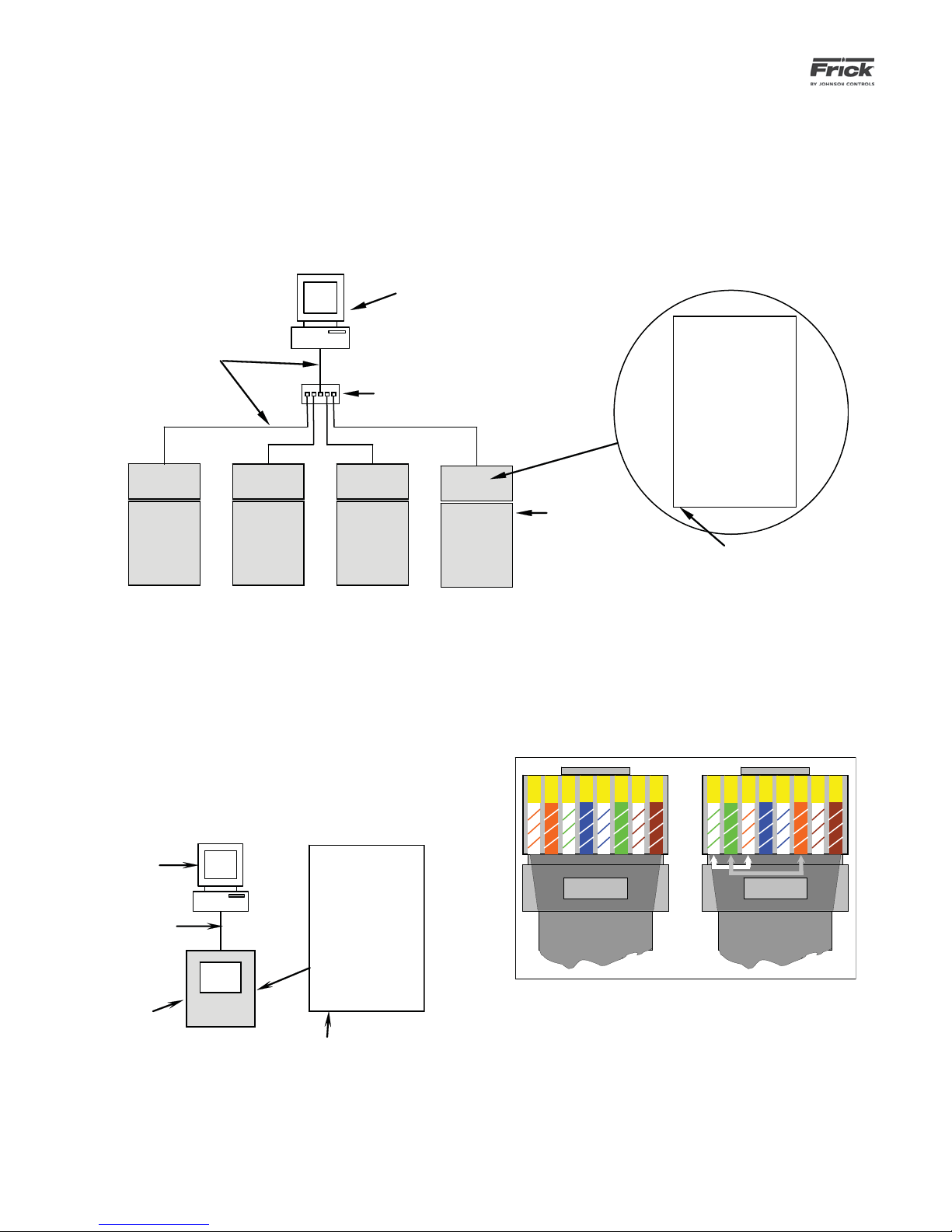
TYPICAL SYSTEM CONFIGURATION
A typical ACUair system may control as few as one or up
to thirty-two remote panels. Each AcuAir® system operates independently of one another yet they may all be
inter-connected via a common Ethernet connection. A
system will include the Quantum™ LX AcuAir® Interface
All network cables are
Pin-to-Pin CAT-5 Cables
Computer
or HMI
Ethernet Hub or
Switch
Panel, remote panel(s), and optionally an Ethernet Hub or
Switch, and a computer with Web Browser.
The Interface Panel can then be connected to an HMI or a
remote computer. Refer to the following pictorial:
Q4 or Q5
Controller
Air Handler
Controllers
Ethernet Port
CONNECTING A COMPUTER DIRECTLY TO A QUANTUM™
LX CONTROL PANEL
Especially for the purpose of maintenance, if you wish to
connect directly to a single panel from a computer (desktop or laptop), you can avoid the switch and use a crossover Cat-5 cable:
Deskto p o r laptop
C omputer
Q4 or Q5
Cross- ove r CAT-
5 Cable
Quantu m™ LX
AcuAi r Control l er
Controller
Ethernet Port
Refer to the following pictorial and color code table to construct a crossover cable:
1 2 3 4 5 6 7
Left (Not Crossed)
Both Ends of a crossover-cable
8
3 6 1 4 5 2 7 8
Right (Crossed)
Page 7
QUANTUM™ LX AcuAir™ CONTROL PANEL
OPERATION
090.510-O (SEPTEMBER 13)
Page 7
OVERVIEW OF OPERATOR INTERFACES
There are two possible methods of viewing and accessing
the user interface. One of these methods is in the form
of a standard Web Browser and the other is an optional
AcuAir® Operator Interface Touch screen.
USING A WEB BROWSER (ETHERNET)
General Description
The Quantum™ LX AcuAir® user interface may be
accessed from any web browser. This feature allows any screen to be viewed from a remote location
without specialized software. An Ethernet connection
to the Quantum™ LX panel must be provided to utilize this feature.
The web browser interface can be viewed from any
desktop or laptop computer, which has access to
the network that the Interface panel is attached to.
Refer to the previous section entitled Connecting A
Computer Directly To A Quantum™ LX Control Panel
when setting up your network.
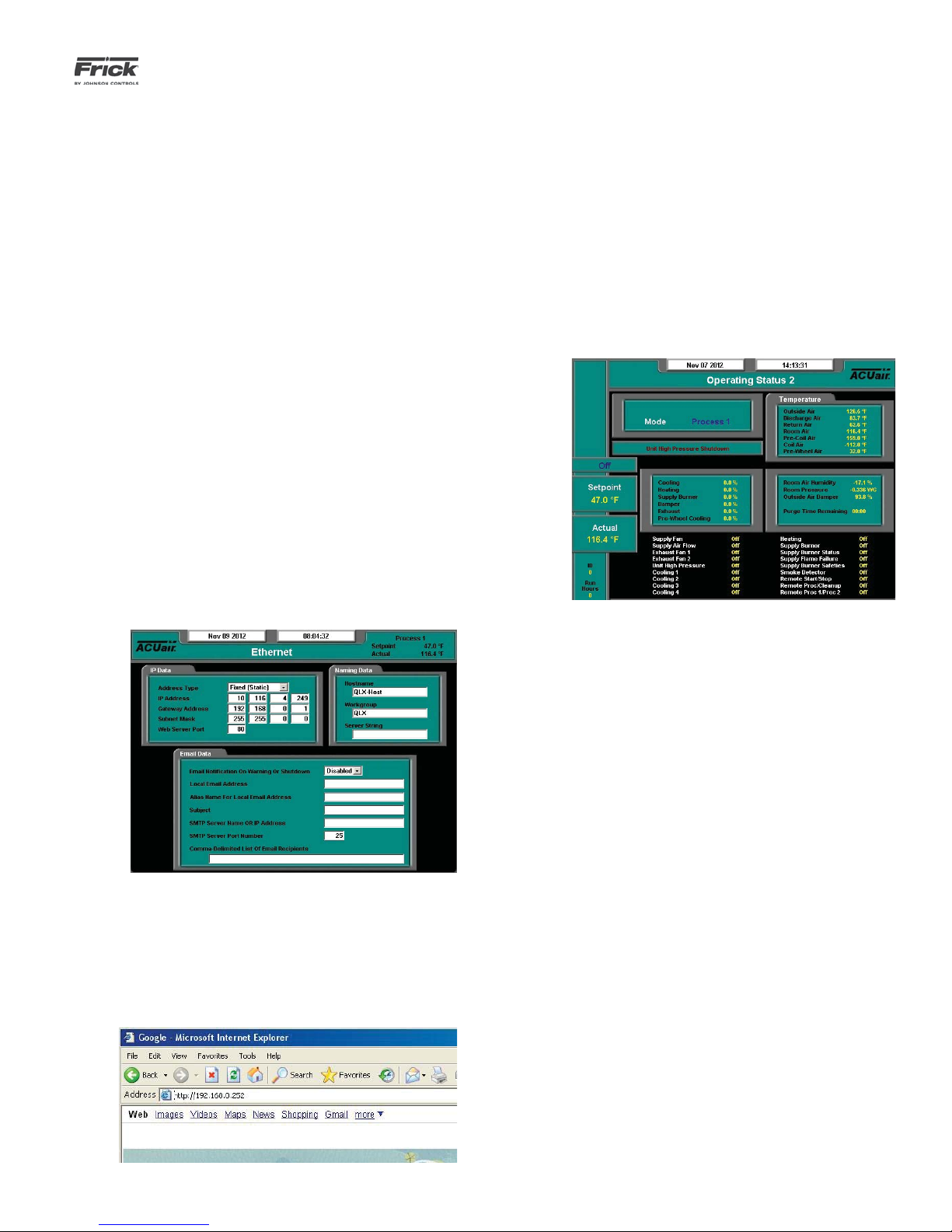
Setup
On the address bar, type the following [ http:// ].
Do not type the brackets. After the http:// type in
the values of the four boxes from IP Address of the
Ethernet Confi guration screen. Place a period (dot)
between each group of numbers. Using the screen
information example used here, the result would be
http://192.168.0.252. Your particular IP Address may
vary from the example shown.
Press the [Enter] key on your computer keyboard,
and if everything is connected and confi gured prop-
erly, the Home screen of the Interface Panel should
now appear on your computer screen (similar to the
following):
Access the Ethernet Confi guration screen at the In-
terface Panel, by selecting Menu > Confi guration >
Ethernet. The following screen will be shown:
Note the values that are displayed in the four boxes
of the IP Address.
At the computer, open the Internet browser (click on
your Internet icon). Once the browser has opened,
look for the address bar, it will appear similar to the
following:
If you experience problems, such as a message stating “Page not found”, consult with your IT department.
Screen Keys
To change screens, setpoints, etc., you simply use a
mouse and the keyboard to view and change data.
All Interface screens will have several buttons on the
right hand side of the screen:
[Menu] – Clicking on this button will cause the
main menu to appear on the left side of the
screen. Clicking a second time will cause the
menu to disappear.
[Submit] – Although this button does not appear
in the example above, it will be present on most
screens. It is used any time that you have modifi ed a setpoint, or made any change to a screen.
Before leaving that screen, you must press the
[Submit] button for the changes to be saved.
Page 8
090.510-O (SEPTEMBER 13)
Page 8
QUANTUM™ LX AcuAir™ CONTROL PANEL
OPERATION
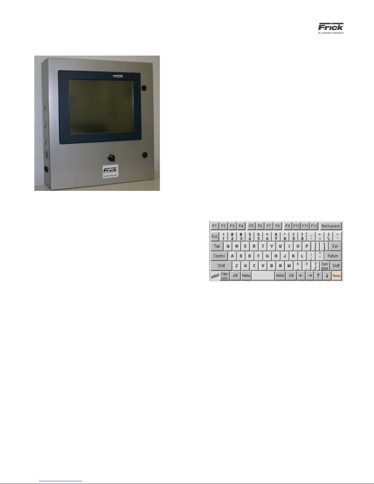
AcuAir® Operator Interface Touch Screen
General Description
This optional user interface has been designed to allow
an operator to effi ciently access, control and monitor the
operation of all Frick AcuAir® units from a single access
point, when all units are connected through a common
Ethernet network. The touch screen control panel is used
for graphic displays. By touching an active area of the display, a data entry box will appear, allowing the operator
to enter different setpoint values, via a keyboard overlay,
that will appear on the screen. The Operator Interface
panel provides a platform to easily navigate between all
networked control systems, as well as a remote access
point which is reachable from any desktop web browser.
Remote access provides users with the ability to connect
to Frick control systems from both home and offi ce, or
any other location providing Internet access.
Touch Screen Calibration
When the panel completes it boot sequence, the user will
be presented with a message box which requests the user
to touch the screen to enter calibration mode. If the user
touches the message box before the 3-second timer expires, the screen will change, presenting the user with
four orange targets. These targets permit the user to calibrate the touch screen’s mouse pointer location. If these
points are not properly set, the mouse pointer will not
appear where the user’s fi nger makes contact with the
screen. Once the screen’s calibration target appear, it is
best to use a dull pointed object to touch each of the four
targets, as a fi nger makes contact with an area too large
to provide accurate calibration.
Browser and Keyboard
Both the browser and keyboard should appear on the
screen once the panel has fi nished its startup sequence.
Each panel is equipped with a program which will restart
the keyboard and browser if either application is closed.
The browser has a small icon in the center of the top tool
bar, which permits the user to return to the panel Home
Page at any time. From the panel Home Page, the Keyboard button can be used to restart the on-screen keyboard should it disappear.
The keyboard can be used to enter text into any fi eld ap-
pearing within a web page. To enter text into a fi eld,
simply touch the desired fi eld in the web browser. If the
fi eld is properly selected, a cursor should appear within
the text fi eld. The user can also drag his/her fi nger over a
segment of text in the fi eld to “select” it. Any key strokes
from the keyboard will then replace the highlighted text.
If the keyboard fails to transmit characters into the desired text fi eld, there could be one of two problems. First,
be sure the text fi eld is selected. Typically the cursor is a
good indicator that focus has shifted to the desired text
fi eld. The second problem involves a keyboard loss of
focus. To resolve this problem, fi rst touch the desired text
fi eld, then touch the [Focus] button on the bottom right-
hand corner of the keyboard, fi nally touch the desired
text fi eld a second time. After this sequence, characters
should be directed to the correct location. This three-step
sequence should be used whenever the keyboard appears
unresponsive.
Keyboard Overlay
Home Page
The panel Home Page displays all the units accessible
through the Operator Interface Panel. Any confi gured
units will appear with an icon and a descriptive label. If an
icon is touched, the web browser will be directed to the
Quantum LX control page. To return to the Operator Interface Panel’s Home Page simply touch the “Home” icon
on the browser’s toolbar.
Admin Home Page
The Operator Interface Panel is equipped with the Admin Home Page to handle various confi guration functions.
This area can be accessed by pressing the Admin button
on the panel’s Home Page. As user name and password
are required to access this area (Username: admin, Password: 2staycold).
Upon entering the admin area, the user will be presented
with the list of all registered units (nothing will be displayed here if no units are registered). If any registered
units are listed, and Edit button at the end of each row
allows the user to change the specifi cations of a specifi c
Page 9

QUANTUM™ LX AcuAir™ CONTROL PANEL
OPERATION
090.510-O (SEPTEMBER 13)
Page 9
unit. A row of Admin buttons across the top of the page
allow the user to add new units, or delete units from the
list of registered units. Each unit must have a unique
name (no two units can have the same name) and an IP
address (the IP address is not required to be unique, so
more than one link can redirect the user to the same unit).
The user can also select the type of unit which results in
an appropriate icon being displayed on the panel Home
Page where all units are listed.
Network Confi guration
In the Admin area, the Network Confi g button can be se-
lected to modify the Operator Interface Panel’s network
settings. When the page is loaded, the current network
settings are displayed for the user to view. It is possible to
change the IP address, subnet mask, and default gateway.
The IP address type can be static or dynamic; the later option requires a DHCP server to be present. Please consult
a network administrator to modify the values correctly. It
is also possible to specify a network name, allowing access to the Panel from a Windows network.
Finally, the web server port can be changed from the Network Confi guration page. This is traditionally set to 80
which all web browsers understand to be the default port.
If this is changed to any other value, the panel can only be
reached from an external computer by appending the port
number to the IP address (e.g. if the Panel’s IP address
is 192.168.0.5 and the web server port is 400, an external web browser will access the panel through the address: 192.168.0.5:400). If this panel does not need to be
reached from an external computer, then the web server
port setting should be disregarded.
In the event the web server port or IP address settings are
changed, the panel may need to perform a reboot before
these changes take effect. This it will do automatically,
and the user will be notifi ed when this is about to occur.
Resetting the IP Address
In the rare occurrence that a local Air Handler loses Ethernet communications with the Web Browser or Operator
Interface Panel, it could be that the unit has an invalid
IP address. One way that this could happen would be if
the unit has just had a program upgrade, without the setpoints being properly saved then restored (the IP address
is stored as a setpoint to the fl ash card).
In order to correct this situation, perform the following
steps:
1. Power down the failing unit.
2. Locate the processor board (located on the inside of the top door).
3. On the Q4 controller only, locate and temporarily
remove LK12 (on the larger board).
4. Power the unit up.
5. Wait for one minute to allow the processor to
fully boot.
6. Power the unit down.
7. Replace LK12 (on the Q4 only).
8. Power back up. The IP address will be automatically set to 192.168.0.105. This address is
known to work, and should solve the problem.
At this point, the unit should show up at the
Web Browser or Interface panel (HMI). If the
user wishes, they may now go into the HMI and
modify the IP address for the unit in question to
the number that they need it to be, or they may
leave it alone.
If the above steps fail to bring the unit back into the
network, you should check the Ethernet cables, hub or
switch, Quantum™ control board, etc.
Page 10

090.510-O (SEPTEMBER 13)
Page 10
QUANTUM™ LX AcuAir™ CONTROL PANEL
OPERATION
Page 11

QUANTUM™ LX AcuAir™ CONTROL PANEL
OPERATION
SECTION 2
SET UP AND CONFIGURATION
090.510-O (SEPTEMBER 13)
Page 11
Page 12
090.510-O (SEPTEMBER 13)
Page 12
QUANTUM™ LX AcuAir™ CONTROL PANEL
OPERATION
SETUP DESCRIPTION
An in depth installation setup is beyond the scope of this guide,
however some basic rules can be observed:
▯ Maintain a total distance of 2000 feet or less between
the Operator Interface Panel, and the very last Remote I/O Panel on any one communications cable
run. As will be explained later, it is possible to have
two separate communications cable runs, depending
upon the total number of Remote I/O Panels. Keep
in mind that neither of these cable runs can exceed
2000 feet in length.
▯ The system is capable of Ethernet communications,
this may be something to consider when placing Interface Panels, as you would want a nearby Ethernet
connection to be available.
▯ Keep all communications wiring in a separate conduit
from control wiring.
▯ When wiring for communications, it is important to
ground only one end of the communications cable.
This ground will be located in the very last Remote
Panel of each communications cable run. If the communications were to be grounded at both ends, then
it would be possible for ground loops to develop,
which could impair communications between panels.
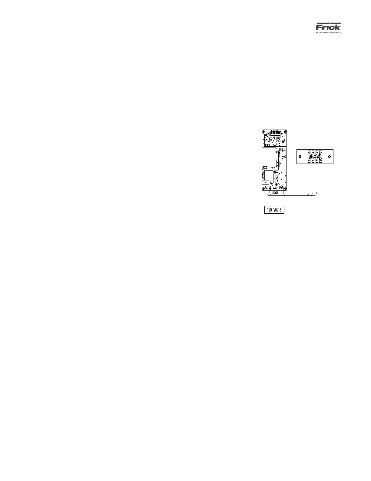
WIRING FOR AC POWER
Interface Panel
The incoming AC power will consist of three 14 AWG
wires (hot, neutral and ground).
▯ Unlatch the two ¼ turn cover latches to the
Interface panel, and open the door.
▯ Inside the enclosure, you will fi nd a power
supply and a terminal strip, as shown here:
• Connect the three incoming AC wires
to the terminal screws as shown previously.
▯ Interface Panels should be located in easy access ar-
eas, and should be mounted at eye level for screen
viewing.
▯ I/O Panels are rated for both indoor and outdoor use.
Although access to the Remote Panels will be rare
after installation and setup, it is still advantageous
to keep them accessible for potential maintenance
situations (reasonable lighting, suffi cient door swing,
etc.).
▯ Install all panels within a convenient distance of a
power source.
• Proceed to the section entitled Checking the AC Power.
Page 13
QUANTUM™ LX AcuAir™ CONTROL PANEL
OPERATION
090.510-O (SEPTEMBER 13)
Page 13
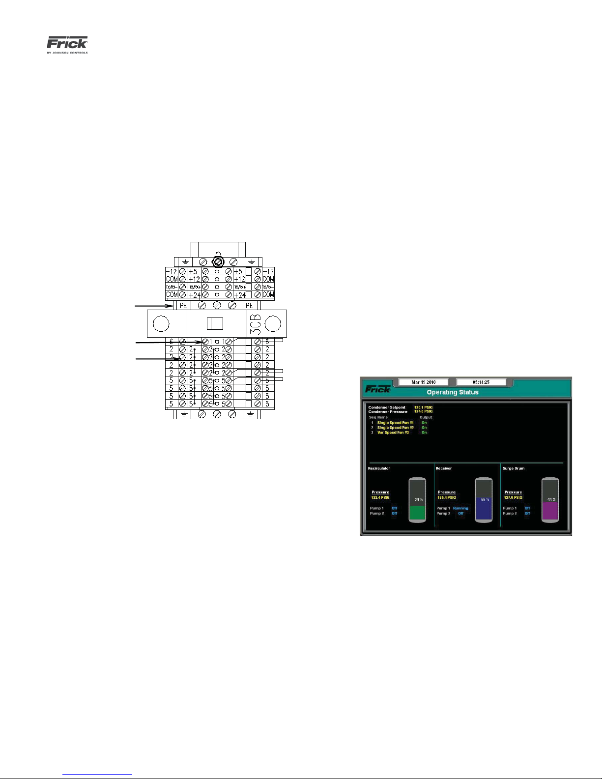
Remote Panel
As with the Interface panel, the incoming AC power
will consist of three 14 AWG wires (hot, neutral and
ground).
▯ Unlatch the two ¼ turn cover latches to the
Interface panel, and open the door.
▯ Inside the enclosure, you will fi nd a long DIN
rail at the left side of the panel. At the top
of the DIN rail is a terminal strip (if the unit
is equipped with an optional panel heater, there will also be a circuit breaker), as
shown here:
Ground
Hot
Neutral
CHECKING THE AC POWER
Interface Panel
▯ Ensure that the Control Power switch is in the
OFF position.
▯ Energize the 120 Volt circuit at its source.
▯ Using a DVM, measure the voltage at the AC
power terminal strip. Ensure that you read approximately 120 VAC between Hot and Neutral,
and Hot and Ground. There must not be voltage
between Neutral and Ground.
▯ Once the incoming voltage has been verifi ed,
turn the Control Power switch to ON.
▯ On the enclosure door, and watch the Quantum™
LX controller (on the backside of the door). You
should notice various LED’s blinking or fl ashing.
▯ Watch the display on the front of the door. Af-
ter a short period of time, you should notice the
display showing a boot sequence. Various text
messages will be shown as it proceeds with the
boot-up process. When fi nished, a screen similar
to the following image should be visible:
▯ Connect the three incoming AC wires to
the terminal screws shown above.
▯ Notice that there are multiple number 2
terminals, connection may be made to
any of them.
▯ Proceed to the section entitled Check-
ing the AC Power.
▯ If the panel has reached the point of showing the
above screen, the boot process was successful.
Turn OFF the Control Power switch, and Deenergize the 120 Volt circuit at its source.
▯ If the panel does not reach to the point of show-
ing the above screen, then troubleshooting will
be required. Refer to end of this guide entitled
Troubleshooting.
Page 14
090.510-O (SEPTEMBER 13)
Black, power ON
plunger
Page 14
QUANTUM™ LX AcuAir™ CONTROL PANEL
OPERATION
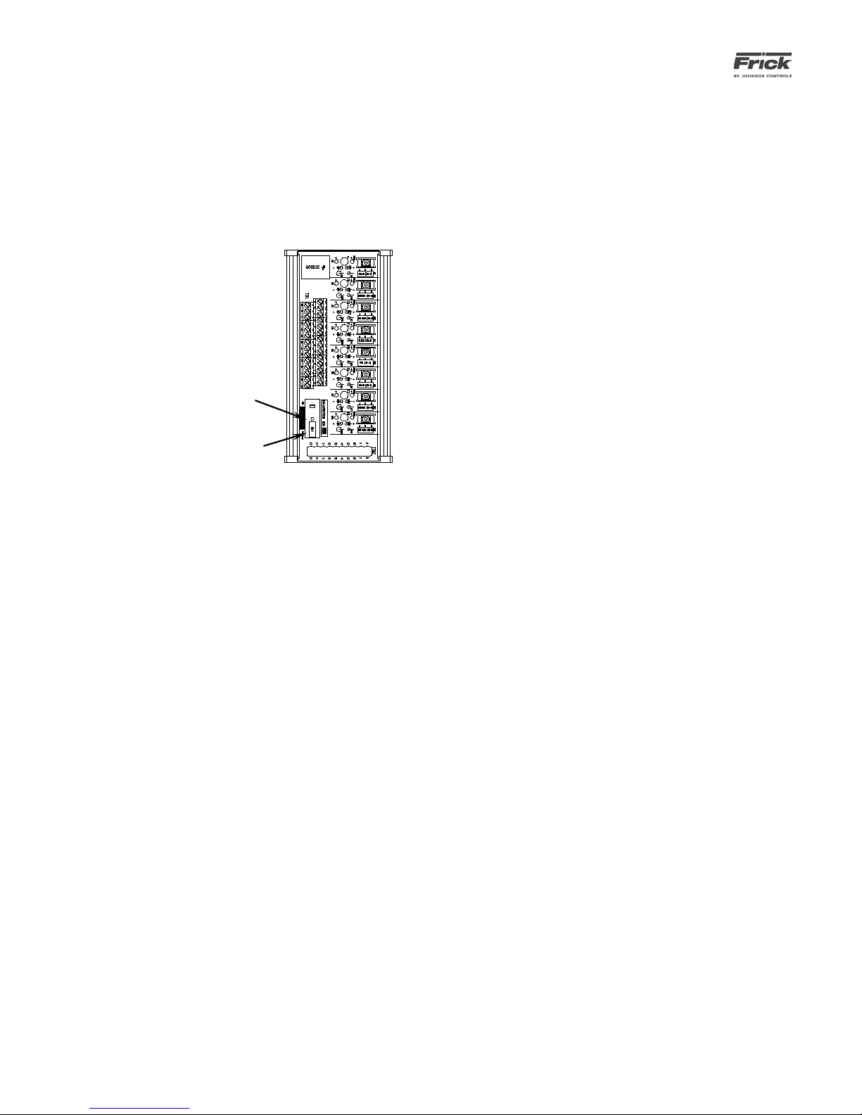
Remote Panel
▯ Unlike the Interface Panel, the Remote panel(s)
▯ Notice in the above pictorial, there is a Red pow-
do not have an external power switch. Instead,
the enclosure will contain two HOA (Hand-Off
Automatic Modules). These modules allow the
technician to override control signals, by manually energizing components. An example of one
of these modules is shown here:
Red, power OFF
tab
er OFF tab, and a black power ON plunger. These
items are located on a circuit breaker for each of
the two HOA modules. Together, they act as the
Control Power switch.
▯ Using a DVM, measure the voltage at the AC
power terminals (1, 2 and PE). Ensure that you
read approximately 120 VAC between Hot and
Neutral, and Hot and Ground. There must not be
voltage between Neutral and Ground.
▯ Once the incoming voltage has been verifi ed,
push in the Black power ON plungers of both
HOA modules.
▯ To the right of the HOA modules are several I/O
boards. There will be at least one Digital board
(recognizable by the plug-in I/O modules), and
one Analog board. Inspect all boards for the
presence of fl ashing, blinking or steadily lit
LED’s. If LED’s are lit on all boards, then power
has been properly applied.
▯ If LED’s are not lit on all boards, then refer to the
section entitled Troubleshooting.
▯ Push each of the Red power OFF tabs down. The
Black power ON plunger should pop up. If the
plunger does not pop up, then the power was
already off. Do this to both HOA modules.
▯ Energize the 120 Volt circuit at its source.
Page 15
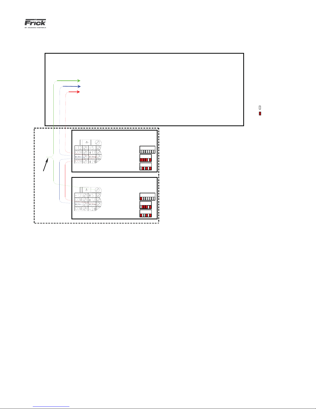
QUANTUM™ LX AcuAir™ CONTROL PANEL
Operator
Interface
Note:Note: For the
DIPSWITCH settings
shown below, a
shaded box indicates
a closed or ON
position, an unshaded
box indicates an open
or OFF position.
= OFF
= ON
Unit 1
Unit 2
OPERATION
090.510-O (SEPTEMBER 13)
Page 15
AcuAir SYSTEM COMMUNICATIONS WIRING DIAGRAM
Twist
Shield
Wires
Together
Shield Wire Not Connected
-RX/TX
+RX/TX
COMM. 4 Cable Run
Un it 1
Analog Board 1
Digital Board 1
Digital Board 2 (opt)
Un it 2
Analog Board 1
Digital Board 1
Digital Board 1 (opt)
Operator
Interface
DIPSWITCH
Settings
12345678
123456
123456
DIPSWITCH
Settings
12345678
123456
123456
Page 16
090.510-O (SEPTEMBER 13)
Page 16
QUANTUM™ LX AcuAir™ CONTROL PANEL
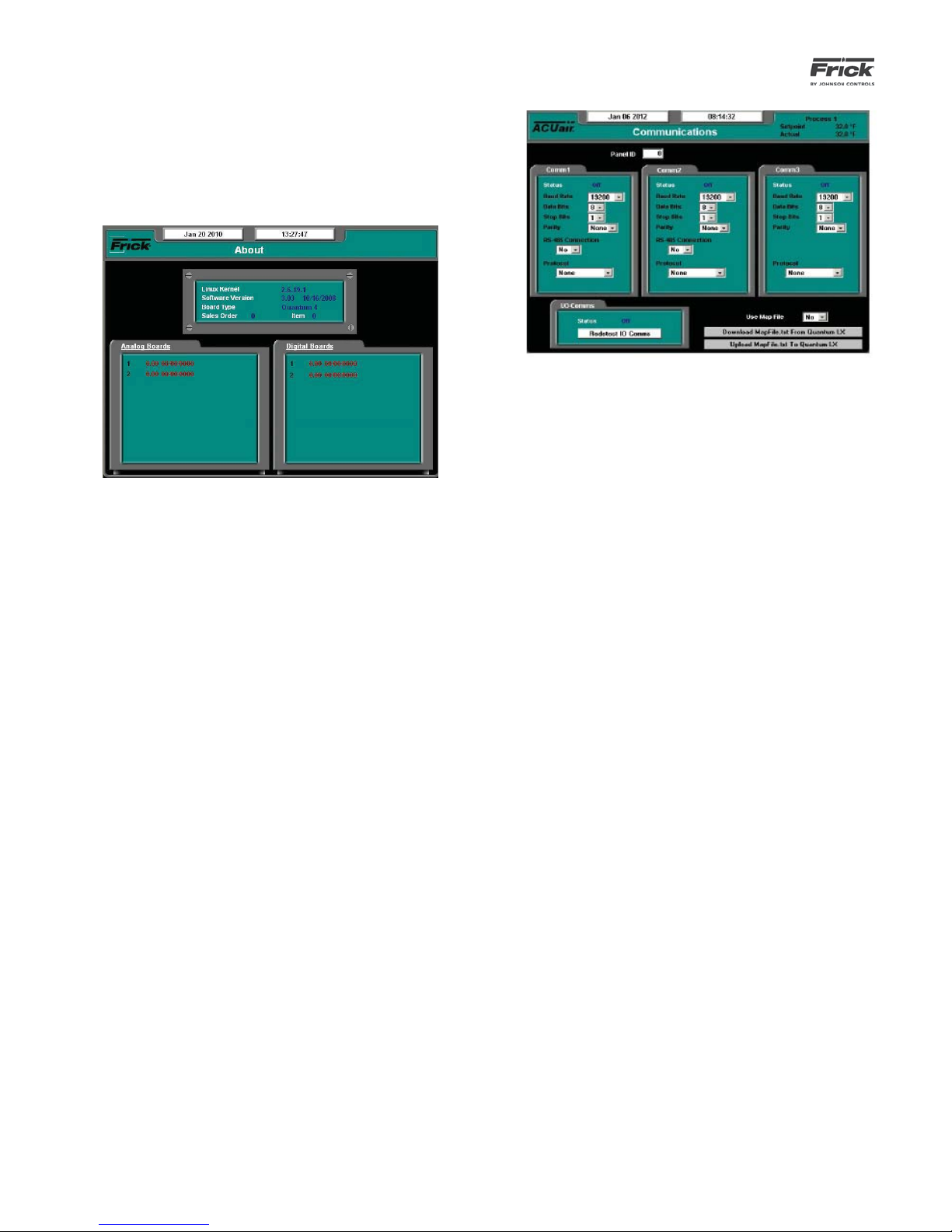
VERIFYING COMMUNICATIONS
The fi rst step in verifying communications is to view what
I/O boards have been detected by the Quantum™ LX Interface Panel. This information will appear on the About
screen, shown here:
Review the information that is shown in the Analog and
Digital Board areas of the screen. Compare what is shown
against what is actually installed.
NOTE: This screen does not update (refresh) automatically. To see any new or different information
that may occur, you must access a different screen,
then come back to this one to see any new data.
Compare what is displayed here with what is actually installed in your system. If a board is physically installed in
a panel, yet does not show up on this screen, then fi nd
the panel that the board is located in, and visually check
the RX and TX LED’s on the board. These LEDs should
be fl ashing. The RX LED will be fl ashing much faster than
the TX LED, but neither should be off completely, as this
indicates a potential wiring problem.
Start by verifying that the boards within the fi rst panel
in the communications line are correctly being detected.
Then move on to the next panel. If the fi rst panel in the
communications daisy chain shows correctly, but there is
a problem with the second panel, then do nothing with
the wiring up to and including the fi rst panel. Inspect in-
stead the last panel for proper communications polarity
and connections. A good indication that you have wires
backwards (reversed) would be that the RX LED is on solid
within the suspect panel. If wiring WAS found to be incorrect, make the correction, and then access the Communications screen by selecting Confi guration from the Main
Menu, then Confi guration, and fi nally Communications.
OPERATION
On the Communications screen shown above, use the
[Tab] key to select Redetect IO Comms and press [Enter].
This will cause the Quantum™ LX controller to reinitiate
all communications with the system. After redetecting IO
Comms, wait about 30 seconds, then access the About
screen once again. If the wiring issue has been corrected,
the questionable I/O board should now be listed, and the
RX/TX LED’s for that board should be fl ashing normally.
When all installed boards have been detected, then the
basic setup is complete. You can now move on to confi g-
uring the system operating parameters.
TROUBLESHOOTING
The following section will help to identify some common
problems that may arise within an ACUair system. Use this
section in conjunction with the 090.510-M (Maintenance)
manual.
1. Quantum™ LX controller does not have any
LED’s lit:
• Check for the presence of 120 VAC power
at the incoming AC terminal strip. (see the
section entitled CHECKING THE AC POWER)
• Check for the presence of proper DC power
to the Quantum™ (refer to the 090.560-M
manual under the section entitled QUANTUM™ LX CONTROL PANEL POWER SUPPLY.
• If the Quantum™ controller has proper DC
voltage applied, then with turn the control
power OFF, remove the program fl ash card,
and recycle the power. If the LED’s do not
start their booting pattern, continue to the
next step.
• Try disconnecting all cables one at a time
(with the exception of the DC power). If the
LED’s start fl ashing normally, then recon-
nect the removed cables one at a time, until
the problem reappears, then troubleshoot
that cable.
• If the DC power to the Quantum™ controller
is normal, and the cables from the previous
step had all been removed without correcting the problem, then the board will need
Page 17

QUANTUM™ LX AcuAir™ CONTROL PANEL
OPERATION
090.510-O (SEPTEMBER 13)
Page 17
replaced.
2. Quantum™ LX appears to boot normally, but
nothing shows on the display:
• Ensure that the display cable is securely
plugged in at both ends.
• On the Q4 only. verify that jumpers LK3 and
LK4 on the Quantum™ are set properly.
Both links should be set to position B.
• Ensure that the connectors on both ends of
backlight inverter board are plugged in securely. Use caution when checking around
the inverter, as high DC voltage is present
when the control power is ON.
• Shine a fl ashlight onto the display screen
at an angle. If the Quantum™ has properly
booted, you should see some text dimly
shown on the screen. If it appears as though
there IS something being displayed, but it is
not visible, then there is a problem with the
backlight, the inverter, cable or Quantum™.
INITIAL SETUP PROCEDURE
The following is a basic guide to unit setup.
1. Confi guration is performed fi rst. Although there
are four different Confi guration screens, only the
Control Confi guration needs to be setup for unit
operation.
To gain access to Control Confi guration, login to
User Level 2. The following items are setup on
the two Control Confi guration pages:
• Mode Confi guration
• Control Temperature
• Control Source
• Supply Burner
• Heating
• Dehumidifi cation
• Damper
• Exhaust
• Exhaust Control
• Exhaust Fan Run Warning
• Supply Fan
• Room Pressure
• Pre-Coil Override
• Discharge Temperature
• Desiccant Heat Source
• Defrost
• Defrost Initiation
• Air Defrost
• Smoke Detector – Enables or Disables
the input for a Smoke Detector. For failsafe operation, this input is energized
when there is no problem and de-energized on a fault such as a fi re.
• Cooling – Used for temperature control. The liquid valve is open because
the control temperature equals or exceeds the liquid on setpoint. If the suc-
tion valve is not a modulating valve, it is
open during cooling. During cooling, a
modulating valve regulates the suction
valve based on its setpoints.
• Pre-Wheel Cooling
2. Setpoints are established next. Each unit must be
setup to the customer specifi c control features
and options to be used by a unit controller board.
This setup should not need to be changed by operators. Setpoints are intended to be accessed
and modifi ed only by a Factory Representative
or Distributor. Only those setpoints that will be
utilized for unit operation need be set. The following is the list of available setpoint screens:
Temperature
• Cooling
• Supply Burner
• Heating
• Pre-Wheel Cooling
Dehumidifi cation
• Desiccant Wheel
• Wheel / Regen Fan
• Regen Burner
Supply Air Flow
• Supply Fan
Defrost
• Defrost Setpoints
• Defrost Schedule
Scheduling
• PID Setup
• Page 1
• Page 2
Communications
Auxiliaries
• Analog Inputs
• Page 1
• Page 2
• Digital Inputs
• Digital Outputs
Panel
3. Calibrate the control devices. Each sensor or
transducer that is utilized by the unit must have
its operating characteristics defi ned. This is
where the controller is told what each devices
high and low operating ranges are, as well as
offsets. The offsets are used to fi ne tune the de-
vice with reference to a known external calibra-
Page 18

090.510-O (SEPTEMBER 13)
Page 18
QUANTUM™ LX AcuAir™ CONTROL PANEL
OPERATION
tion device:
• Temperature
• Pressure
• Miscellaneous
• Auxiliaries
• Analog Outputs
4. From Security Setup, establish the desired
access rights of the operators.
The panel now provides quick access to the most important
information and controls of the units and their subsystems.
OPERATOR ACCESS
Operator access to this system is through various screens.
A screen is the physical representation of data on the display. Each screen has a title area. The title is descriptive
of the screen. The current date and time is shown in this
title area. The day of the week, Sunday (Sun.) through
Saturday (Sat.) is displayed. The month of the year from
January (Jan.) to December (Dec.) is displayed. The day of
the month from 1 to 31 and the year from 0001 to 9999
is displayed. The time displayed is the current time in 24
hours (military) format. The hours, minutes and seconds
are displayed.
Some screens are for informational purposes only, and
cannot be modifi ed. These screens typically show ana-
log values such as temperature and humidity, which are
strictly functions of an associated sensor, and as such,
cannot be modifi ed. Other screens show setpoint values
which can be changed, in order modify the units operating
characteristics. For easier viewing, related information is
separated into boxes. Sometimes selections are hidden
when that the feature is unavailable.
TO CHANGE SETPOINTS
The setpoints defi ne the operation and limits of each unit.
These setpoints can be change by operators in the fi eld.
These setpoints are stored on the Compact Flash card.
NOTE: Setpoints are not lost after power is interrupted.
However, we suggest that a list of Setpoints be recorded
and stored safely to facilitate reentry, in case there is a
need to return to the original settings.
1. The data entry fi elds are identifi ed by a black box
with a white interior. The data is shown in black
text. When on a screen that has adjustable setpoints, tab to the setpoint box that you wish to
modify (or select it on a web browser).
2. The current value of that setpoint is shown. Use
the keypad to enter the new value. Typing a new
value will completely erase the old value.
3. Press the keypad [ENTER] or [Tab] key to input
the new data in the data entry fi eld and to move
to the next data entry fi eld.
4. If the data entered into the setpoint box is valid,
press the keyboard [ENTER] key. After all the
setpoint changes on this screen have been entered, press the [SUBMIT] button to save the
setpoint changes to memory.
5. If the value is out of bounds, an error message
box displays the proper range of values. Press
the [OK] button to acknowledge the error message. Re-enter a correct value.
Page 19

QUANTUM™ LX AcuAir™ CONTROL PANEL
OPERATION
SECTION 3
GRAPHIC SCREENS
090.510-O (SEPTEMBER 13)
Page 19
Page 20
090.510-O (SEPTEMBER 13)
Page 20
Date
QUANTUM™ LX AcuAir™ CONTROL PANEL
OPERATION
GRAPHIC SCREENS
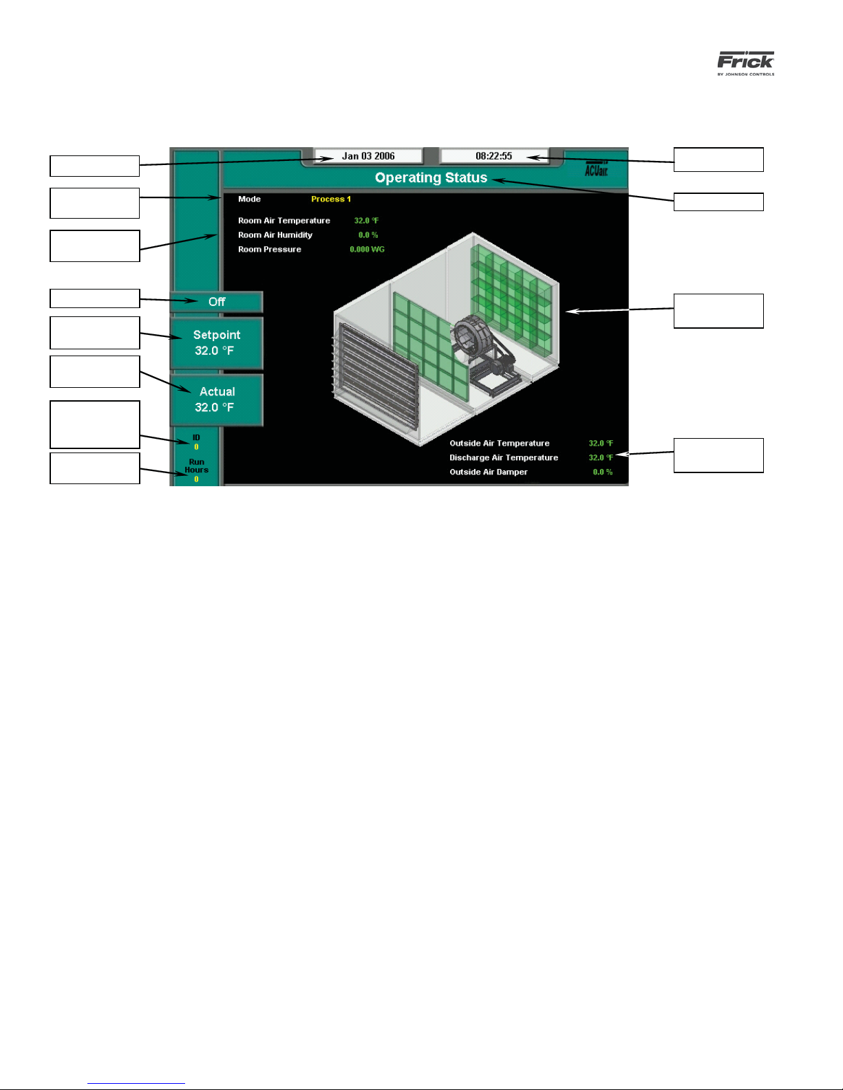
OPERATING STATUS
Time
Mode of Operation
Process Room
Readings
Status Box
Setpoint
Value
Actual
Value
Panel ID of the unit
being displayed
Unit
Run Time
The most important information about the unit is displayed. In
the middle of the screen is a diagram of an AcuAir® air handling unit that shows the current state of the unit. The graphic
simulation shown on the screen will vary depending upon the
installed options. The following items may be shown:
• The supply fan and both exhaust fans spin.
• A fl ame is displayed when the burner is on.
• The cooling coils are colored blue when they are on,
white when they are off and red when in defrost.
The following information is shown on this screen:
Screen Title
Graphic Simulation
Analog
Readings
MODE OF OPERATION – The current mode of the unit,
either Cleanup or Process.
• Process 1 and Process 2 – The unit is maintaining optimum air conditions for processing product.
• Cleanup - The unit is modifying air conditions to
support the cleanup procedure.
PROCESS ROOM READINGS – Values related to current
mode will be shown here:
DATE - The actual date will be displayed in this box.
The date must fi rst be set correctly on the Confi guration
screen. Once set, the date will be automatically adjusted
for at the end of each month, much like the calendar feature of most modern watches. The primary use of the date
feature is to provide a date stamp for Warnings and Shutdowns. Refer to the section entitled Setting the Date and
Time for further information.
TIME - The actual time will be displayed in this box.
The time must fi rst be set correctly on the Confi guration
screen. The time will also need to be adjusted for those
locations which observe Daylight Savings Time. The primary use of the time feature is to provide a time stamp
for Warnings and Shutdowns. Refer to the section entitled
Setting the Date and Time for further information.
SCREEN TITLE - This is the title for the screen that is
showing. Each screen will have a title. The Quantum™ LX
manuals will extensively refer to screens by these names.
When referred to in these manuals, screen names will be
shown in bold italic print, such as Operating Status.
• Room Air Temperature
• Room Air Humidity
• Room Pressure
STATUS BOX –
• Off – The unit is neither running nor is starting.
• Running – The unit is in a normal run condition,
air fl ow has been detected.
• Starting - The unit has turned on but air fl ow has
not been detected.
SETPOINT VALUE - This is the setpoint maintained by
the control.
ACTUAL VALUE - The actual reading of the temperature
that was chosen as the control input.
ID - The number that has been assigned to this particular
unit on the Communications Setup screen.
RUN HOURS – The total number of hours that the Air
Handler has run since the unit was installed.
Page 21
QUANTUM™ LX AcuAir™ CONTROL PANEL
OPERATION
090.510-O (SEPTEMBER 13)
Page 21
ALARM MESSAGE - Warnings and Shutdown messages are
displayed in the lower left corner of the screen. This area will
be blank if there are no current Warnings or Shutdowns.
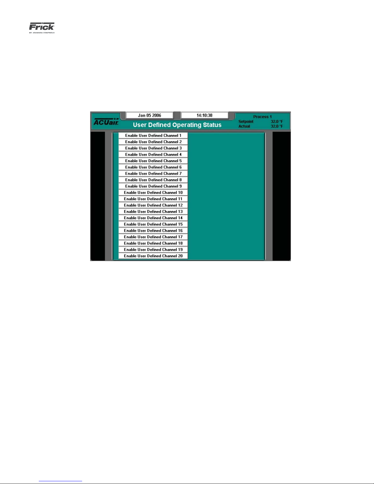
USER DEFINED OPERATING STATUS
ANALOG READINGS BOX - The following analog input readings are possible. They are shown if they were enabled during
setup:
• Outside Air Temperature
• Discharge Air Temperature
• Outdoor Air Damper
DESCRIPTION: The purpose of this screen is to allow the user
to assign additional analog channels to be more readily viewable. Since the main Operating Status (Home) screen is capable of only showing a limited number of pre-assigned analog
values, it may be desirable for the user to have a method of
viewing additional information that they can select, on a common screen. They may even select values that are already being displayed on the Operating Status screen, as well as values
that are not shown there.
This screen is provided to allow the user to view up to 20 different analog channels of their choosing.
As an example of how this screen works, assume that in addition to the data that is shown on the Operating Status screen,
the user would like to monitor the Outside Air Temperature,
Room Air Humidity and Pre-coil Air Temperature, all on the
same screen (this one). Notice that Outside Air Temperature
and Room Air Humidity are already shown on the Operating
Status (Home) screen, but the Pre-coil Air Temperature is
shown on the Operating Status 2 screen. In order to set this
screen up to show these three values, the user would highlight
the Enable User Defi ned Channel 1 (or whatever channel they
wish to use), by selecting it with the mouse. Once the box is
highlighted, click on it to cause the possible settings for the
channel to appear. Use the mouse to scroll through the list.
When the selection that you want to use has been highlighted,
click on it to select it. Once selected, a value will appear to
the right of the list, which corresponds to the analog value for
that channel.
The following selections may be shown on this screen:
Outside Air Temperature
• Discharge Air Temperature
• Room Air Temperature
• Return Air Temperature
• Pre-Coil Air Temperature
• Coil Air Temperature
• Room Air Humidity
• Room Pressure
• Differential Pressure
• Outside Air Damper
• Coil Temperature 1- 4
• Pre-Wheel Regen Air Temperature
• Post-Wheel Regen Air Temperature
• Wheel Differential Pressure Switch
• Auxiliary Analog 1 - 20
• None
Page 22
090.510-O (SEPTEMBER 13)
p
Page 22
Date
Mode of
eration
O
Warning /
Shutdown
Status
Run Status Box
Setpoint
Value
Actual
Value
QUANTUM™ LX AcuAir™ CONTROL PANEL
OPERATION
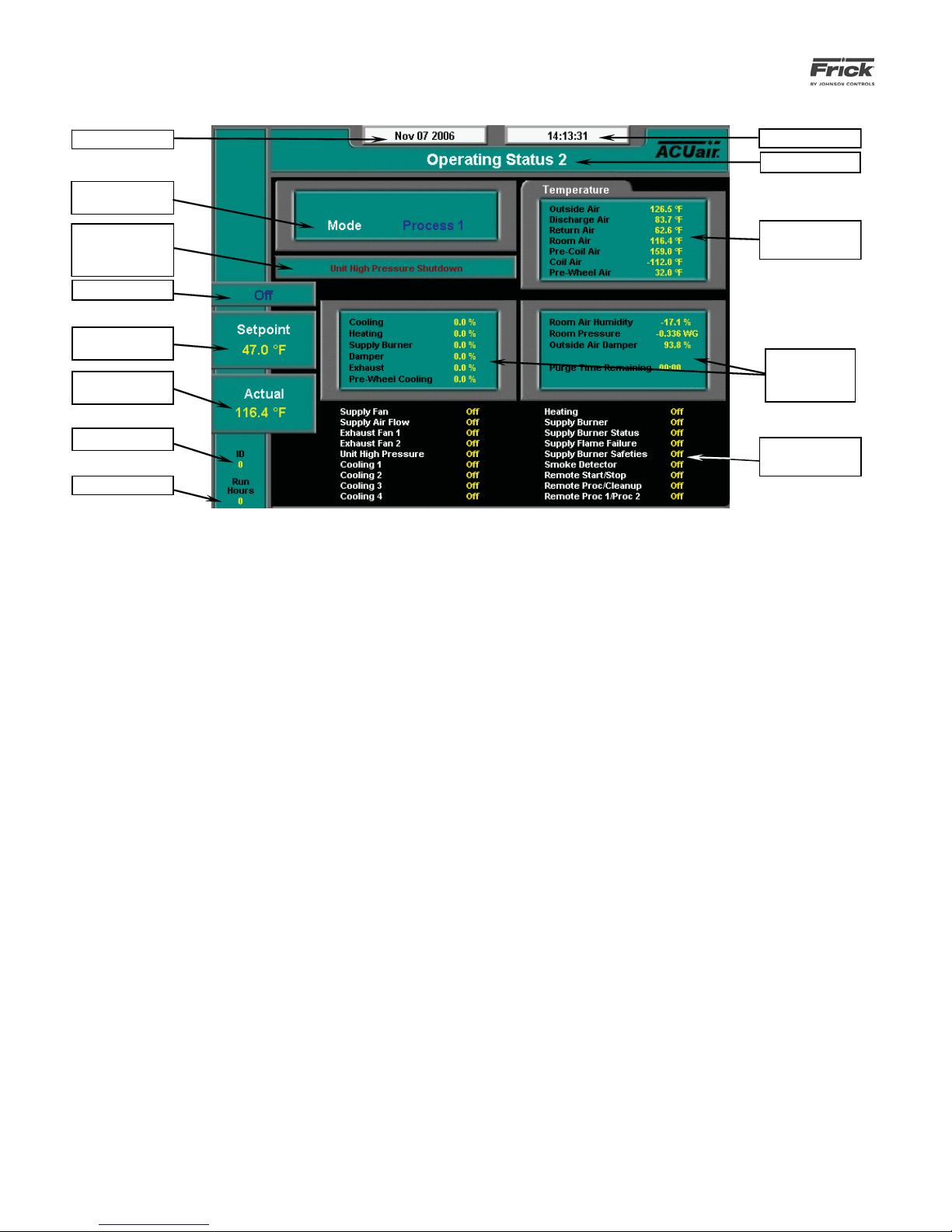
OPERATING VALUES – OPERATING STATUS 2
Time
Screen Title
Temperature
Readings
Additional
Analog
Readings
Panel ID
Run Time
DESCRIPTION: The Operating Status 2 screen shows addition-
al unit information that cannot be shown on the fi rst Operating
Status screen. Along the sides of the page are labels identifying the various areas of the screen.
The following information is shown on this screen:
DATE - The actual date will be displayed in this box.
The date must fi rst be set correctly on the Confi guration
screen. Once set, the date will be automatically adjusted
for at the end of each month, much like the calendar feature of most modern watches. The primary use of the
date feature is to provide a date stamp for Warnings and
Shutdowns.
TIME - The actual time will be displayed in this box.
The time must fi rst be set correctly on the Confi guration
screen. The time will also need to be adjusted for those
locations which observe Daylight Savings Time. The primary use of the time feature is to provide a time stamp for
Warnings and Shutdowns.
SCREEN TITLE - This is the title for the screen that is
showing. Each screen will have a title. The Quantum™ LX
manuals will extensively refer to screens by these names.
When referred to in these manuals, screen names will be
shown in bold italic print, such as Operating Status.
ID - The number that has been assigned to this particular
unit on the Communications Setup screen.
I/O
Status Box
WARNING/SHUTDOWN STATUS BOX - The Warning/
Shutdown Status is displayed below the Mode of Operation status box. This status box is blank with no message
if there are no warnings or shutdowns present.
If a Warning or Shutdown occurs, a message will be
shown, identifying the type of warning or shutdown. The
defi nitions for the two types of messages are as follows:
WARNING - A specifi c warning message will be
shown when a warning is present. A warning is a
condition that requires operator acknowledgement
but allows the Unit to continue to run if it is already
running. A Warning message indicates that a warning
setpoint has been reached, or exceeded.
SHUTDOWN - This specifi c shutdown message will
be shown when a shutdown is present. A shutdown
is a condition that requires an operator to acknowledge, and causes the Unit to shut down. A Shutdown
message indicates that a shutdown setpoint has been
reached, or exceeded.
To clear a Warning or Shutdown, the operator must access the Current Safeties screen, and acknowledge the
Warnings/Shutdowns by pressing the [Clear Safeties] button. If the conditions that originally caused the Warning
or Shutdown have not been corrected, the Warning or
Shutdown will continue to re-occur until the problem has
been identifi ed and corrected.
RUN HOURS – The total number of hours that the Air
Handler has run since the unit was installed.
Page 23

QUANTUM™ LX AcuAir™ CONTROL PANEL
OPERATION
090.510-O (SEPTEMBER 13)
Page 23
I/O STATUS BOX - The present operating status of the digital
I/O is shown. One of the following messages is displayed:
• On – The channel is energized or turned on.
• Off - The channel is de-energized or turned off.
The following inputs are shown in the fi rst block (if they were
enabled during setup).
• Supply Fan Motor
• Supply Air Flow Switch
• Exhaust Fan #1
• Exhaust Fan #2
• Unit High Pressure
• Cooling Stage #1
• Cooling Stage #2
• Cooling Stage #3
• Cooling Stage #4
• Heating
• Supply Burner
• Supply Burner Status
• Supply Flame Failure
• Supply Burner Safeties
• Smoke Detector
• Remote Start/Stop
• Remote Process/Cleanup
• Remote Process 1/Process 2
Page 24
090.510-O (SEPTEMBER 13)
Page 24
QUANTUM™ LX AcuAir™ CONTROL PANEL
OPERATION
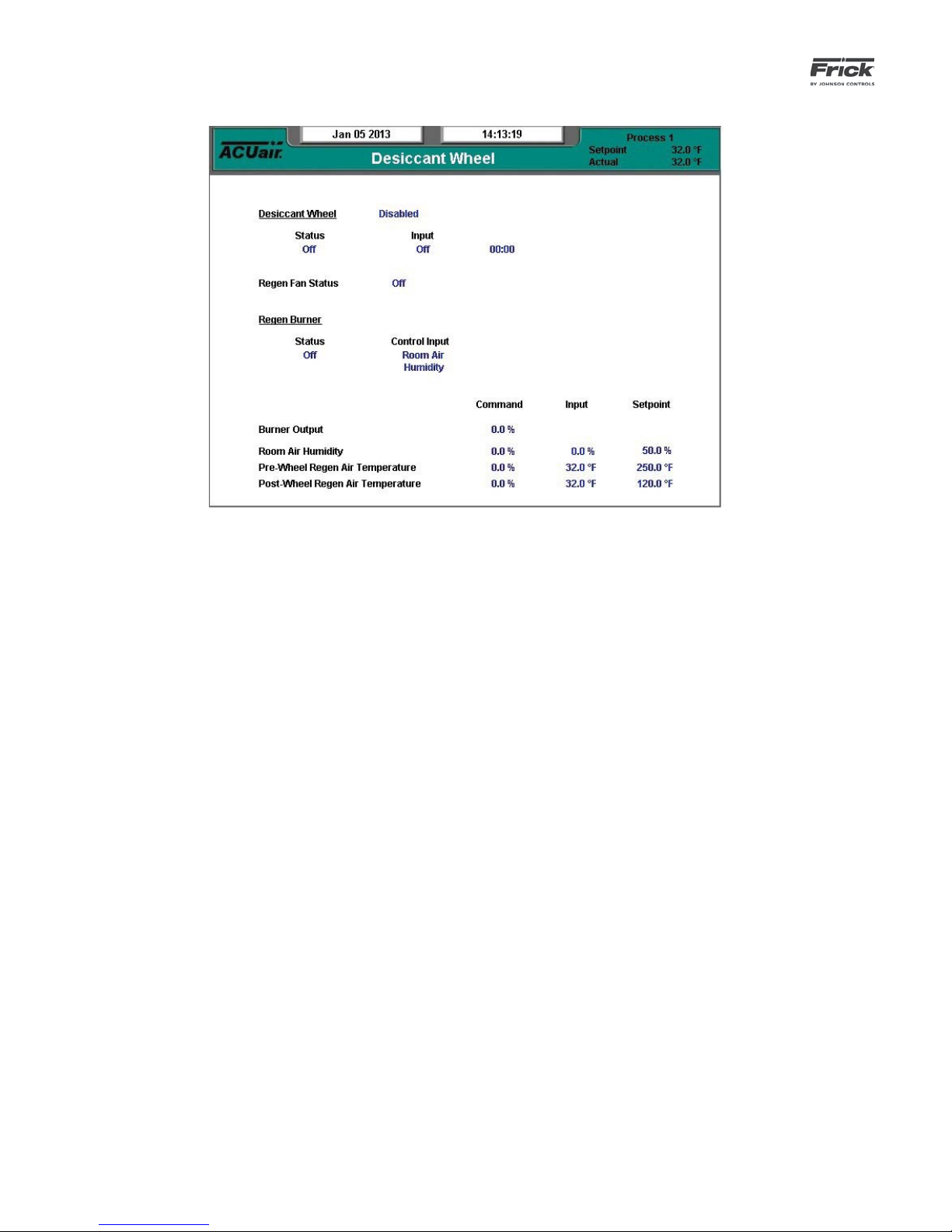
OPERATING VALUES – DESICCANT WHEEL
DESCRIPTION: The Desiccant Wheel screen shows informa-
tion relating to operation of the Desiccant Wheel.
This screen is for informational purposes only. There are no
setpoints or data to be modifi ed from here, only viewed.
The status of the following conditions can be viewed here:
Desiccant Wheel
• Active
• Status
• Input
• Time
Regen Fan Status
• On
• Off
Regen Burner
• Status
• Control Input
Burner Output
• Command
Room Air Humidity
• Command
• Input
• Setpoint
Pre-Wheel Regen Air Temperature
• Command
• Input
• Setpoint
Post-Wheel Regen Air Temperature
• Command
• Input
• Setpoint
Page 25

QUANTUM™ LX AcuAir™ CONTROL PANEL
OPERATION
SAFETIES - Current Safeties
090.510-O (SEPTEMBER 13)
Page 25
DESCRIPTION: The Current Safeties screen shows the Warn-
ings and Shutdowns that have recently occurred (up to 50).
When a warning or shutdown is triggered, a blue descriptive
message shows on this screen. The date and time of the warning or shutdown occurrence is shown to the right of its description. The most recent message will appear on the top line
of the screen with the oldest appearing at the bottom. When
a Warning or Shutdown is logged to this screen, it will also be
logged to the Safety History screen.
The following Current Safeties screen key is provided:
[Clear Safeties] - Selecting this key will clear all warnings
and/or shutdowns from this screen. This will also place a
date/time stamp for the corresponding entry on the Safety History screen showing that the particular Warning or
Shutdown was cleared. Clearing the entry on the Current
Safeties screen, will not clear it from the Safety History
screen.
To resume normal operation it will be necessary to go through
the following steps:
1. Correct the condition(s) causing the warning.
2. Press the [ALARM SILENCE] key. (This action may
precede correcting the condition(s) causing the warning).
Or, go to step 3.
3. To clear or reset the Warnings/Shutdowns screen
and turn off any warning annunciation device, from the
screen, press the [Clear Safeties] key. This will also clear
the WARNING or SHUTDOWN message from the Operating Status screen.
4. If the conditions causing the warning have not been
corrected or a new fault has occurred, a new WARNING
or SHUTDOWN message will appear. The Safety History
screen keeps a record of the warnings and shutdowns.
This information will help troubleshoot persistent operational problems.
Refer to the Alarms/Shutdowns Message section for a list of
all the possible conditions.
Page 26

090.510-O (SEPTEMBER 13)
Page 26
QUANTUM™ LX AcuAir™ CONTROL PANEL
OPERATION
SAFETIES - Safety History
DESCRIPTION: The Safety History screen shows the warnings
and shutdowns that have recently occurred (up to 50 maximum). When a warning or shutdown is triggered, a blue descriptive message shows on this screen. The date and time of
the warning or shutdown occurrence is shown to the right of
its description, followed by the date and time that the safety
was cleared. The most recent message will appear on the top
line of the screen with the oldest appearing at the bottom.
It is possible to view the conditions that existed on the Operating Status screen at the exact moment that a condition
occurred. Use the mouse to select (highlight) a warning or
shutdown and then click on it to view its associated Freeze
(Operating Status) screen.
Freeze Screen Description
This Freeze screen provides a snapshot of the values that
were current at the time of the latest shutdown. The information on the Freeze screen can help the user to identify the cause of a fault, which occurred when no one
was present. The Freeze screen freezes the information of
the Operating Status screen AT THE MOMENT OF AN AIR
HANDLER WARNING OR SHUTDOWN. The Freeze screen
has the same appearance and contains the same information as the Operating Status screen. (For a description
of the information presented by the Freeze screen, refer
to the Operating Status screen). The Freeze screen will
retain the information generated by a warning or shutdown. The last fi fty warnings/shutdowns Freeze screens
are saved. This data is saved during a power outage.
Page 27
QUANTUM™ LX AcuAir™ CONTROL PANEL
OPERATION
SYSTEM STATUS - Trending - Trending Setup
090.510-O (SEPTEMBER 13)
Page 27
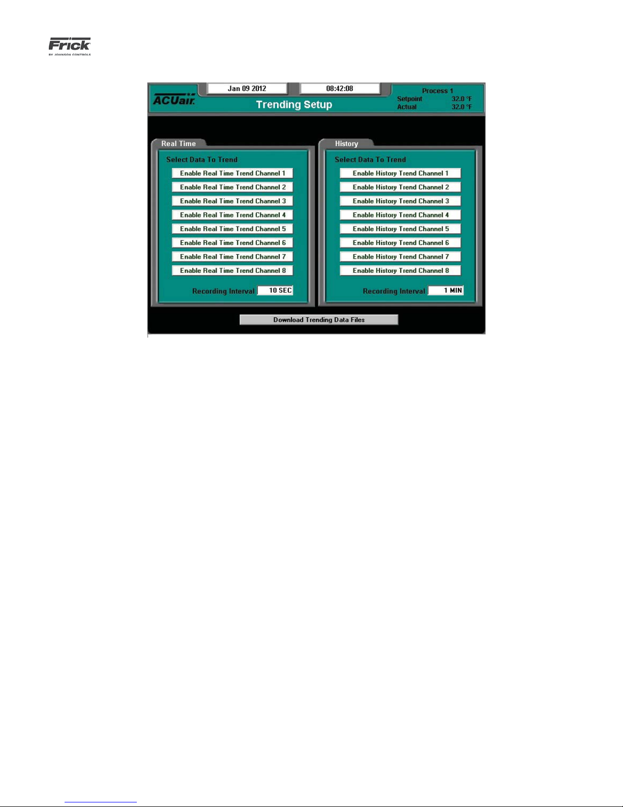
DESCRIPTION: This is the Trending Setup screen. Up to eight
channels can be monitored in real time trending, and up to
eight channels monitored in history trending.
Real Time Trending - is a method by which the user can set
the Quantum™ LX to map real-time events to a graphic chart
format. Using this feature allows for a live snap-shot of recent
unit process characteristics, such as temperature, pressure
and humidity readings. The events that occur will scroll across
the screen from left to right, at a speed that is determined by
the recording interval. Real Time trending information is also
stored to a log fi le, which provides a time/date stamp for each
of the selected channels, as well as the value of the reading for
that channel. This log fi le can be viewed on the Real Time Data
Log screen. Trending data is lost upon power cycle.
The following setpoint is provided:
Real Time Recording Interval – The time interval that
defi nes how often the real time trending data values are
updated. This value may be set for any time duration between 1.0 second and 86,400.0 seconds (24 hours).
History Trending - is a method by which the user can set the
Quantum™ LX to record historical events to a graphic chart
format. This feature is similar to Real Time trending, except
that the data points can be set separately, the rate at which
the graphic chart is updated can be set to a different rate, and
the data is not lost at power cycle. Using this feature allows
for the recording of recent event characteristics, such as temperature, pressure and humidity readings. The events that occur will scroll across the screen, at a speed that is determined
by the recording interval.
The following setpoint is provided:
History Recording Interval – The time interval that defi nes how often the history trending data values are updated. This value may be set for any time duration be-
tween 1.0 minute and 60.0 minutes (1 hour).
To program this screen with the data you wish to trend, highlight the Enable Real Time Trend Channel 1 (or whatever channel you wish to use), by selecting it with the [Tab] key. Once
the box has been selected, a drop down menu will appear for
that channel. On the right hand side of the drop down box will
be an arrow. Selecting the arrow will to cause all the possible
settings for the channel to appear. Use the up and down arrow
keys, then press [Enter] to select. Once selected, the value for
this channel will be automatically trended and shown on the
Real Time Trending graph (or History Trending Graph), as well
as on the Real Time Trending Data Log (Or History Trending
Data Log).
The following screen command keys are provided:
• Outside Air Temperature
• Discharge Air Temperature
• Room Air Temperature
• Return Air Temperature
• Pre-Coil Air Temperature
• Coil Air Temperature
• Room Air Humidity
• Room Pressure
• Outside Air Damper
• User defi ned analog input #1-20
• None
When in Remote Mode (not at the panel), the following key is
provided:
Download Data Trending Files – Clicking on this button
initiates a downloading of the Real Time and History data
fi les from the Quantum™ LX to the remote computer (the
computer that you are monitoring from). These fi les can
then be imported into a database such as Excel™.
Page 28

090.510-O (SEPTEMBER 13)
Page 28
QUANTUM™ LX AcuAir™ CONTROL PANEL
OPERATION
A window will appear on the computer screen, showing
two fi les:
• Realtimexx.csv
• Historyxx.csv
The xx in both of these fi les will be replaced with the ID
number of the Quantum™ LX. When the fi les appear in
SYSTEM STATUS - Trending – Real Time Trending
the screen window, simply right click on either fi le, and
select from the menu “Save Target As…”, and save the
fi les to a convenient location. By using Windows Internet
Explorer™, you can then double click on the fi le, and it will
automatically open the fi le in Microsoft Excel™. The data
can then be used in whatever way the user would like.
DESCRIPTION: This is the Real Time Trending screen. This
screen will display in a graphical chart format the data values
as selected on the Real Time Trending Setup screen. Each of
the possible eight selectable channels will be shown at the
bottom of the screen, each in a different color. The color data
values displayed in the chart correspond to the matching color
of the trending channels at the bottom of the screen. A total
of 900 Realtime events can be trended. Realtime events are
lost upon each power cycle.
The following are the possible data channels that may be
shown here:
• Outside Air Temperature
• Discharge Air Temperature
• Room Air Temperature
• Return Air Temperature
• Pre-Coil Air Temperature
• Coil Air Temperature
• Room Air Humidity
• Room Pressure
• Outside Air Damper
• User defi ned analog input #1-20
• None
Page 29
QUANTUM™ LX AcuAir™ CONTROL PANEL
OPERATION
SYSTEM STATUS - Trending – History Trending
090.510-O (SEPTEMBER 13)
Page 29
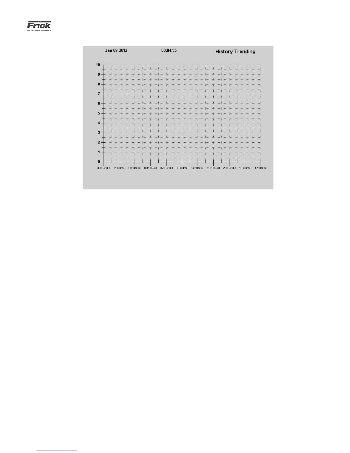
DESCRIPTION: This is the History Trending screen. This screen
will display in a graphical chart format the data values as selected on the History Trending Setup screen. Each of the possible eight selectable channels will be shown at the bottom
of the screen, each in a different color. The color data values
displayed in the chart correspond to the matching color of the
trending channels at the bottom of the screen.
History trending can save up to 2000 values for each selected
channel. History data is stored in Flash memory. Flash memory
is non-volatile and all information is retained even if the power
to the panel is lost. The interval at which the data is saved can
be adjusted.
The following are the possible data channels that may be
shown here:
• Outside Air Temperature
• Discharge Air Temperature
• Room Air Temperature
• Return Air Temperature
• Pre-Coil Air Temperature
• Coil Air Temperature
• Room Air Humidity
• Room Pressure
• Outside Air Damper
• User defi ned analog input #1-20
• None
Page 30
090.510-O (SEPTEMBER 13)
Page 30
QUANTUM™ LX AcuAir™ CONTROL PANEL
OPERATION
SYSTEM STATUS - Trending – Real Time Data Log
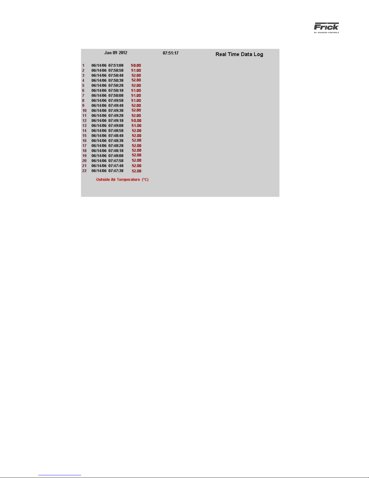
DESCRIPTION: This screen will display in a tabular format, the
numerical data values as selected on the Real Time Trending
Setup screen. Each trending channel will be listed at the bottom of the screen in a specifi c color that matches all data as-
sociated with that channel.
The following are the possible data channels that may be
shown here:
• Outside Air Temperature
• Discharge Air Temperature
• Room Air Temperature
• Return Air Temperature
• Pre-Coil Air Temperature
• Coil Air Temperature
• Room Air Humidity
• Room Pressure
• Outside Air Damper
• User defi ned analog input #1-20
• None
Up to eight of these data selections may be activated for recording at any one time. If eight items are selected, and you
wish to view one more, you will fi rst need to de-activate one
that is already chosen fi rst. Selected data items will appear
with an asterisk (*) in front of the data on this listing.
Page 31
QUANTUM™ LX AcuAir™ CONTROL PANEL
OPERATION
SYSTEM STATUS - TRENDING – HISTORY DATA LOG
090.510-O (SEPTEMBER 13)
Page 31
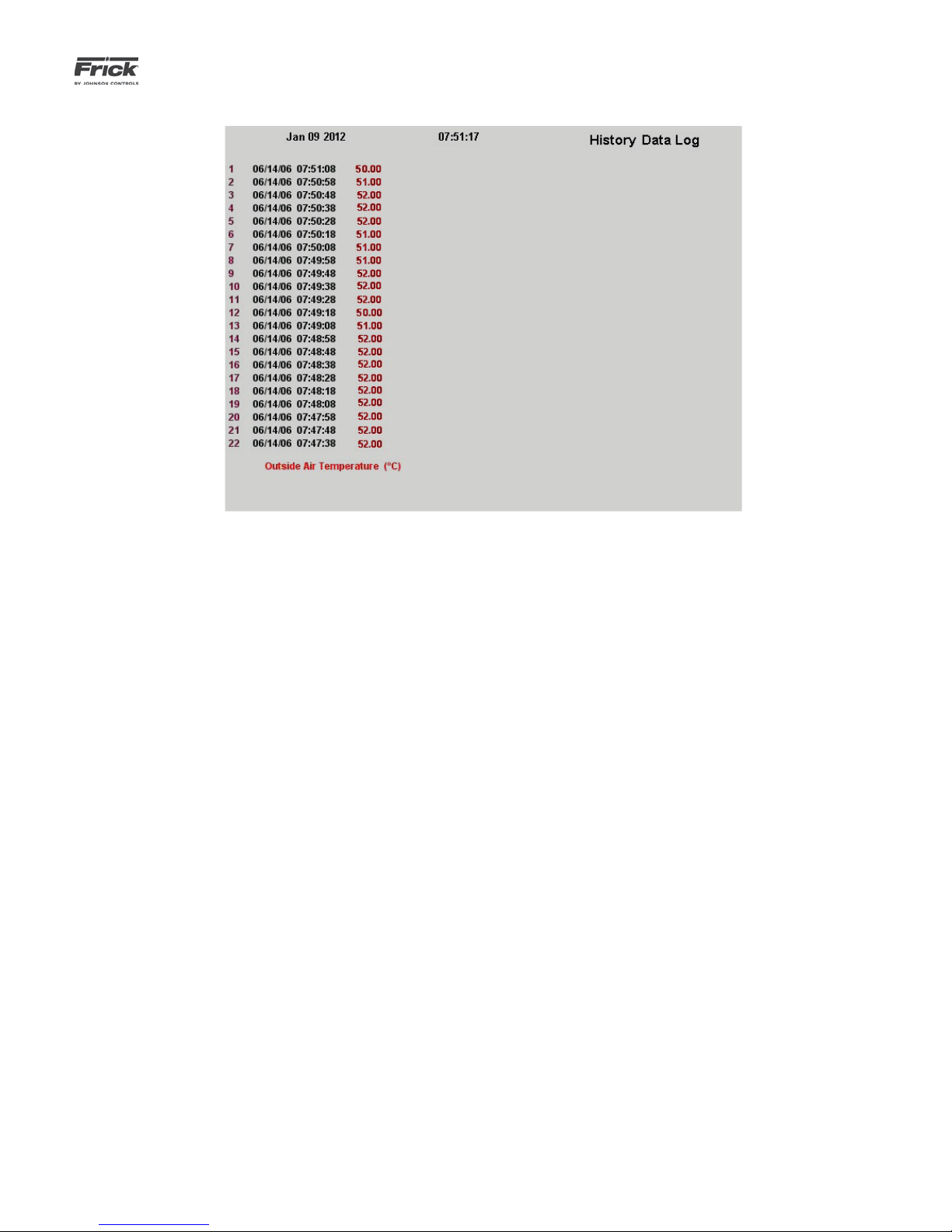
DESCRIPTION: This screen will display in a tabular format, the
numerical data values as selected on the History Trending Setup screen. Each trending channel will be listed at the bottom of
the screen in a specifi c color that matches all data associated
with that channel.
The following data channels may be shown here:
• Outside Air Temperature
• Discharge Air Temperature
• Room Air Temperature
• Return Air Temperature
• Pre-Coil Air Temperature
• Coil Air Temperature
• Room Air Humidity
• Room Pressure
• Outside Air Damper
• User defi ned analog input #1-20
• None
Page 32
090.510-O (SEPTEMBER 13)
Page 32
QUANTUM™ LX AcuAir™ CONTROL PANEL
OPERATION
SYSTEM STATUS - MAINTENANCE
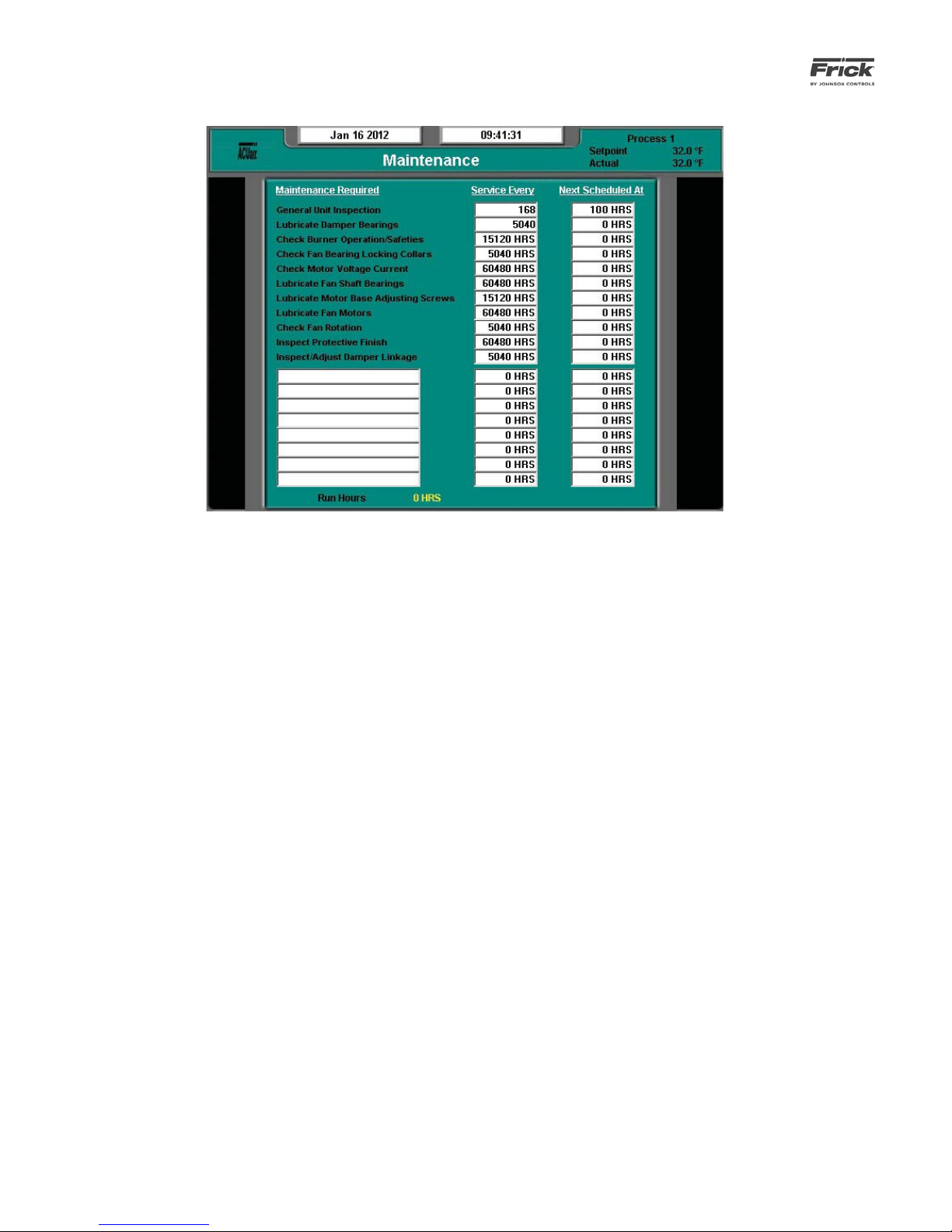
DESCRIPTION: This screen allows the user to view up to elev-
en (11) pre-programmed maintenance schedules, as well as
eight (8) user defi nable maintenance schedules. Each of the
user defi ned schedules may be given a unique name.
This screen allows the user to schedule up to nineteen different routine maintenance operations. As an example, the above
screen shows a row labeled as General Unit Inspection. The
next column (Service Every) on the same row has a value of
168 Hrs. The second column (Next Scheduled At) of this row
has a value of 100 Hrs. When the air handler is running, this
time value is being clocked. After 100 Hrs. of run time (the
value from the Next Scheduled At column), a message will be
generated and placed on the Event Log screen. This particular
message will read Maintenance – General Unit Inspection. This
is to notify the operator that it is time to inspect the unit. At
this point, the operator should request that the maintenance
personnel take appropriate action. The user should access the
Event Screen on a regular basis (at least once per week) to
review the information provided there.
Once a value from the Service Every column has been reached,
an appropriate message will be entered into the Event Log, and
the values for the row will be automatically updated, with new
values as predetermined by an internal programmed maintenance schedule. The values for the Next Scheduled at column
are based upon the Air Handler Run Time hours (shown at the
bottom of this screen).
The last eight rows allow the user to schedule customized
maintenance tasks. A brief description of each row can be en-
tered into one of the text fi elds under the Maintenance Re-
quired column, while the two right had columns permit the
user to specify scheduling requirements.
Modifying numerical values
To modify any of the numerical boxes on this screen, simply use the mouse key to click in one of the boxes. When
the box that you wish to change is highlighted, you may
enter the new value using the keyboard, then press the
[Enter] key to accept the value.
Modifying Text (User Defi ned) Boxes
To modify any of the text boxes on this screen, simply use
the mouse to click on the box. When the box that you
wish to change is highlighted, use the keyboard to enter
the desired text. Press the [Enter] key to accept the text.
The user may type in a custom name up to 20 characters
long.
The following additional information is provided on this screen:
Run Hours - The value shown here is the total number of
hours that the air handler blower has actually been in the
running state. This value can be reset (or changed to any
value from 0 to 1,000,000 Hours) from the Panel screen.
Page 33
QUANTUM™ LX AcuAir™ CONTROL PANEL
OPERATION
SYSTEM STATUS – Event Log
090.510-O (SEPTEMBER 13)
Page 33
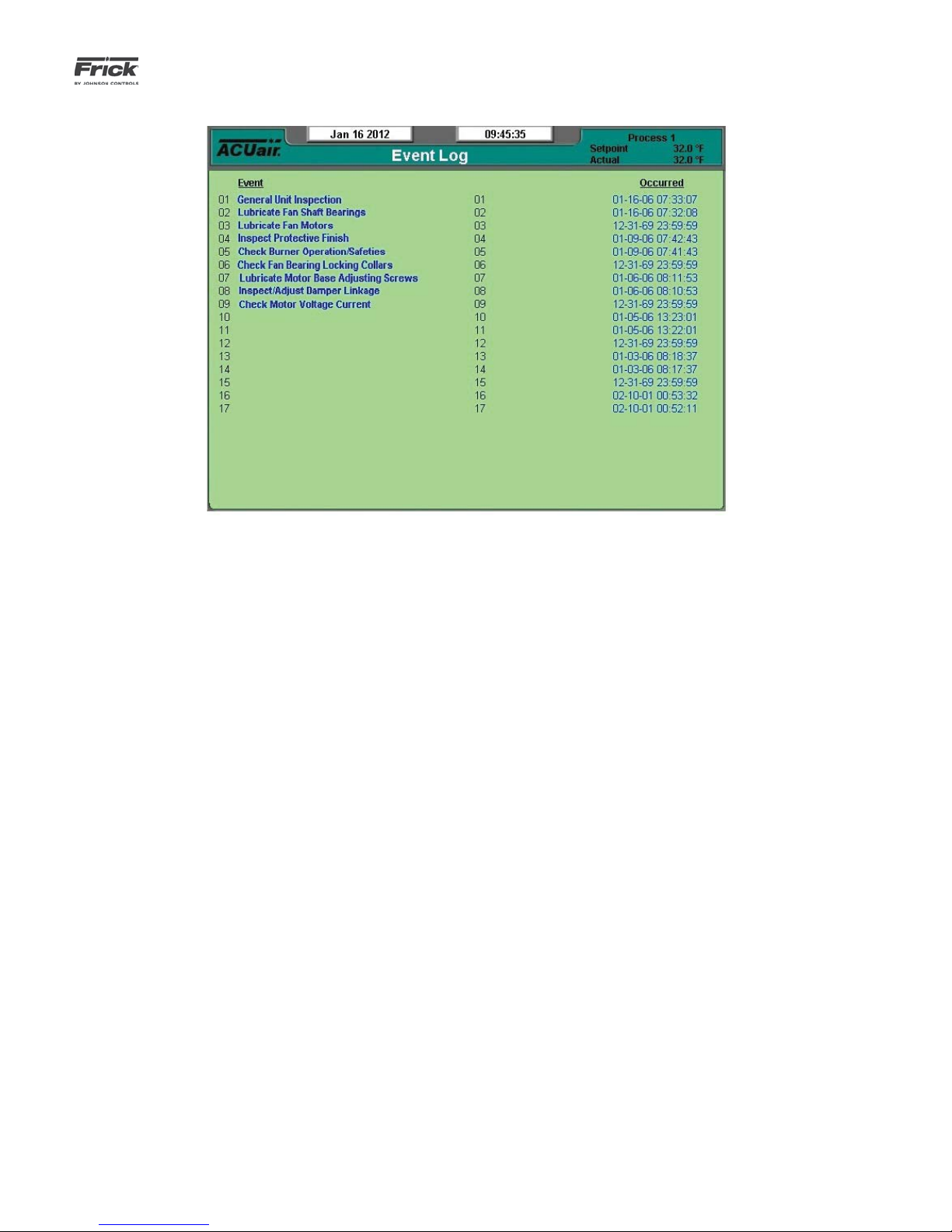
DESCRIPTION: This screen is used to log certain messages
and events that are generated through normal unit operation.
Occurrences such as normal power up and power down sequences, as well as all maintenance schedule messages (see
the Maintenance screen for more information on these messages).
The messages that appear on this screen cannot be cleared,
they will be stored indefi nitely. The user can use the arrow
keys on the keypad to scroll up and down through the list.
Page 34
090.510-O (SEPTEMBER 13)
Page 34
QUANTUM™ LX AcuAir™ CONTROL PANEL
OPERATION
SETPOINTS – Temperature – Cooling
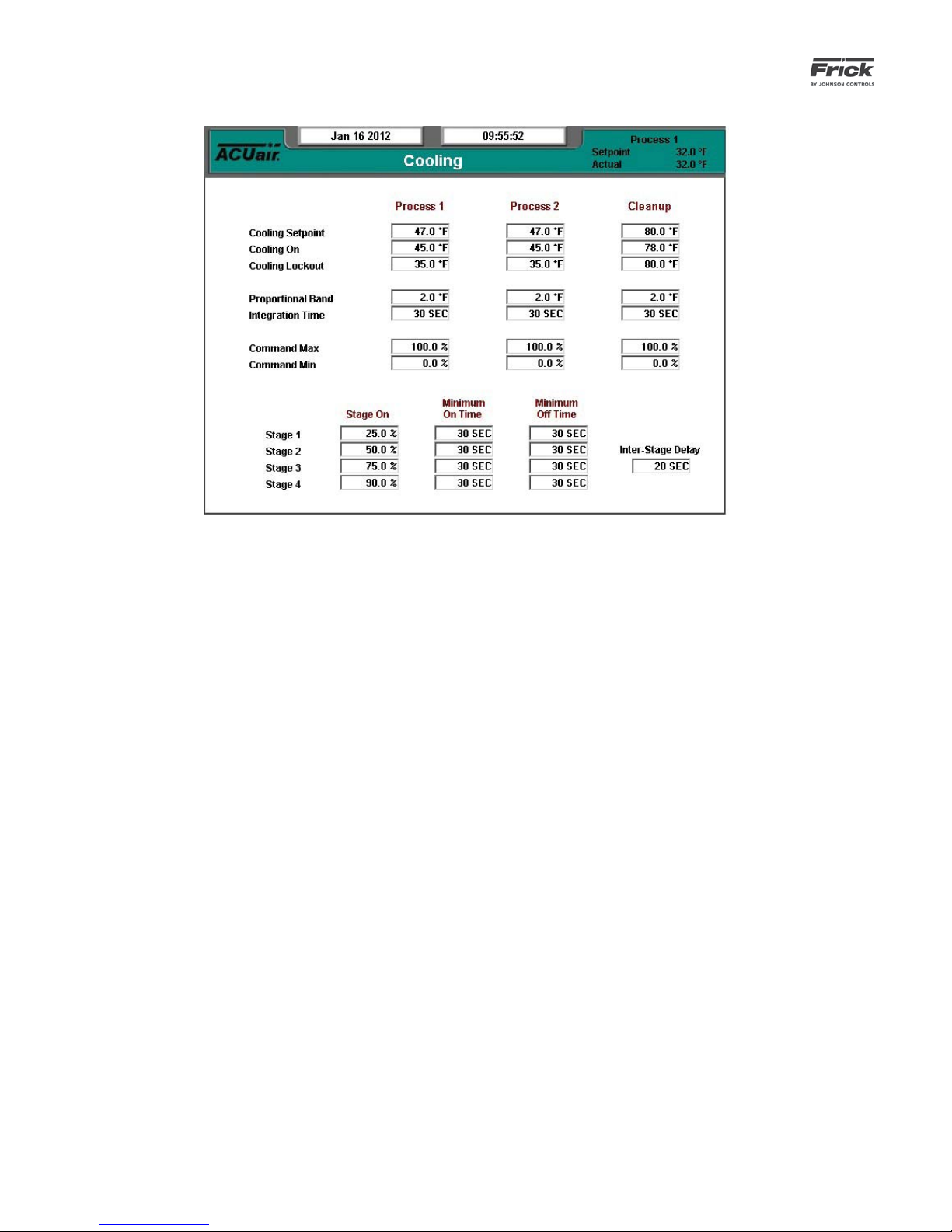
DESCRIPTION: This screen is used to setup Cooling Control
setpoints for Process and Cleanup Modes.
Cooling Control Setpoints are used to maintain temperature in
Process and Cleanup Modes. A PID loop is the control structure
used to move the temperature toward setpoint. The Cooling
Proportional Band and Integration Time Setpoints allows for
the confi guration of this PID control. The Command Max and
Min Setpoints set the range for the PID loop.
In Process Mode, the unit will maintain the Cooling Setpoint.
While the Outside Air Temperature is greater than Cooling
Lockout, the unit attempts to hold the Return Air Temperature
at the Cooling Setpoint. If the Return Air Temperature drops
below the Cooling Setpoint, the PID output is set to the Command Min Setpoint. The PID output remains at the Command
Min Setpoint until the Return Air Temperature rises above the
Cooling Setpoint. If the Outside Air Temperature drops below
the Cooling Lockout, cooling is temporarily disabled, as it is
not needed.
In Cleanup Mode, as cooling is required, the unit will maintain
the Cooling Setpoint. While the Outside Air Temperature is
greater than the Cooling Lockout, the unit attempts to hold the
Discharge Air Temperature at the Cooling Setpoint. If the Discharge Air Temperature drops below the Cooling Setpoint, the
PID output is set to the Command Min Setpoint. The PID output
remains at the Command Min Setpoint until the Discharge Air
Temperature rises above the Cooling Setpoint. If the Outside
Air Temperature drops below the Cooling Lockout, cooling is
temporarily disabled, as it is not needed.
The Stage On setpoints specify the PID output that will bring
on Stages #1 through #4. The Minimum On Time Setpoint
forces the stage to remain on for a minimum time while the
Minimum Off Time Setpoint forces the stage to remain off for
a minimum time.
Together they keep the unit from rapidly cycling on and off.
When the unit has more than one stage of cooling, the InterStage Delay Setpoint holds subsequent stages off for a minimum amount of time after a previous stage has turned on.
Below is an example of cooling in Process Mode:
Setpoints Cooling Setpoint = 35 F
Cooling On = 33 F
Cooling Lockout = 30 F
Proportional Band = 4 F
Integration Time = 0 Sec.
Command Max = 95%
Command Min = 5%
Stage #1 Setpoint = 25%
Stage #2 Setpoint = 50%
Minimum On Time = 30 Sec.
Minimum Off Time = 30 Sec.
Inter-Stage Delay = 20 Sec.
The Cooling PID output determines the amount of cooling
required and regulates the amount of cooling applied to the
room. As long as the Outside Air Temperature remains below
30 F (Cooling Lockout), cooling is disabled and the Cooling PID
output remains at 0%. When the Outside Air Temperature rises
above 30 F, the Cooling PID output is calculated based on the
Return Air Temperature and the Cooling Lockout Setpoint.
When the Integration Time is set to 0, the PID calculation reduces to a simple Proportional Band calculation. While the Return Air Temperature is greater than 39 F (the Cooling Setpoint
plus the Proportional Band) the PID output will remain at 95%
(Command Max). As the Return Air Temperature drops below
39 F, the PID output drops based on the Proportional calculation. At 38 F the PID output is 75%, at 37 F the output is 50%, at
36 F the output is 25% and below 35 F the PID output drops to
5% (Command Min). When the Return Air Temperature begins
Page 35

QUANTUM™ LX AcuAir™ CONTROL PANEL
OPERATION
090.510-O (SEPTEMBER 13)
Page 35
to rises the process repeats in reverse.
As the Cooling PID output varies, the Cooling Stage #1 and #2
outputs are controlled by the Stage #1 and Stage #2 Setpoints.
When the PID output rises above 25% Cooling Stage #1 is
turned on. If the PID output continues to rise and reaches 50%,
Cooling Stage #2 is turned on, provided that at least 20 Sec.
(Inter-Stage Delay) have passed since Stage #1 was turned on.
Both outputs remain on until the PID output drops below 50%.
At this point Cooling Stage #2 is turned off if at least 30 Sec.
(Minimum On Time) have passed since Stage #2 was turned
on. If the PID output drops below 25 % Stage #1 is turned
off if at least 30 Sec. (Minimum On Time) have passed since
Stage #1 was turned on. After either Stage #1 or #2 have been
turned off, 30 Sec. (Minimum Off Time) must pass before that
same stage can be turned on again.
Page 36

090.510-O (SEPTEMBER 13)
Page 36
QUANTUM™ LX AcuAir™ CONTROL PANEL
OPERATION
SETPOINTS – Temperature – Supply Burner
The Supply Burner Control Setpoints listed above maintain
temperature during Process and Cleanup Mode.
While heating with a Modulated Burner, the unit tries to maintain the Supply Burner Setpoint temperature. When the Outside Air Temperature drops below the Supply Burner Lockout,
the Burner digital output is turned on and the Burner analog
output is set to the Command Min Setpoint. When the Burner
Status input detects that the fl ame is on, the Heating PID out-
put begins to control the Burner analog output and to move
the Discharge Air Temperature toward the Supply Burner Setpoint. The Proportional Band and Integration Time allows for
the confi guration of the PID control. The Command Max and
Min set the range for the PID loop.
The Burner digital output remains on and the Burner analog
output continues to modulate based on the Heating PID output
until the Outside Air Temperature rises above the Supply Burner Lockout. At this point, the Burner digital output is turned
off and the Burner analog output is set to the Command Min
Setpoint. The unit's Heating control remains in this state until
the Outside Air Temperature drops or the unit exits Process or
Cleanup Mode.
The Minimum On Time Setpoint sets the minimum amount of
time the Burner digital output must be energized after it is
turned on. The Burner digital output will remain energized for
the Minimum On Time even if the Outside Air Temperature
rises above the Supply Burner Lockout. In the same way, the
Min Off Time Setpoint sets the minimum amount of time the
Burner digital output must be de-energized after it is turned
off. The Burner digital output will remain de-energized for the
Min Off Time even if the Outside Air Temperature drops below
the Supply Burner Lockout.
The following setpoint boxes have been provided:
[Supply Burner Setpoint]
• Cleanup
• Process 1
• Process 2
[Supply Burner On]
• Cleanup
• Process 1
• Process 2
[Supply Burner Lockout]
• Cleanup
• Process 1
• Process 2
[Proportional Band]
• Cleanup
• Process 1
• Process 2
[Integration Time]
• Cleanup
• Process 1
• Process 2
[Command Max]
• Cleanup
• Process 1
• Process 2
[Command Min]
• Cleanup
• Process 1
• Process 2
[Minimum On Time]
Page 37

QUANTUM™ LX AcuAir™ CONTROL PANEL
OPERATION
090.510-O (SEPTEMBER 13)
Page 37
[Minimum Off Time]
[Burner Start Delay]
[Burner Ramp Time]
[Burner Limit Setpoint]
[Burner Limit Proportional Band]
[Smoke Detector Shutdown Delay]
[Burner Safeties Shutdown Delay]
SETPOINTS – Temperature – Heating
The following setpoint boxes have been provided:
[Heating Setpoint]
• Process 1
• Process 2
• Cleanup
[Heating On]
• Process 1
• Process 2
• Cleanup
[Heating Lockout]
• Process 1
• Process 2
• Cleanup
[Proportional Band]
• Process 1
• Process 2
• Cleanup
[Integration Time]
• Process 1
• Process 2
• Cleanup
[Command Max]
• Process 1
• Process 2
• Cleanup
[Command Min]
• Process 1
• Process 2
• Cleanup
[Stage 1]
• Stage On
• Minimum On Time
• Minimum Off Time
• Inter-Stage Delay
[Stage 2]
• Stage On
• Minimum On Time
• Minimum Off Time
Page 38

090.510-O (SEPTEMBER 13)
Page 38
QUANTUM™ LX AcuAir™ CONTROL PANEL
OPERATION
SETPOINTS – Temperature – Pre-Wheel Cooling
This feature provides for a one or two stage cooling coil placed
before the Desiccant wheel. The pre-wheel cooling coil is designed to regulate the temperature of the air in order to optimize the effi ciency of the desiccant wheel.
The following setpoint boxes have been provided:
[Pre-Wheel Cooling Setpoint] - Temperature at which
PI control governs the pre-wheel cooling analog channel.
• Process 1
• Process 2
• Cleanup
[Pre-Wheel Cooling On] – The temperature at which the
pre-wheel liquid digital output is turned on.
• Process 1
• Process 2
• Cleanup
[Pre-Wheel Cooling Lockout] - If the outside air falls below this temperature, pre-wheel cooling will not operate.
• Process 1
• Process 2
• Cleanup
[Proportional Band] - The temperature range over which
the PID control will be managing pre-wheel cooling (provided Integration Time is not set to zero, in which case it
will be strictly proportional). If the Setpoint is 50 degrees
and the Proportional Band is 5 degrees, the PI control
will set the output to Command Min if the temperature
is below 45 degrees (Setpoint minus Proportional Band).
When the temperature is between 45 and 50 degrees,
the PI control will be decreasing the output towards the
Command Min value. When the temperature is between
50 and 55 degrees (Setpoint plus Proportional Band) the
PI control will be increasing the output in a manner to
bring the pre-wheel temperature toward the setpoint).
Above 55 degrees the output will be set to Control Max.
• Process 1
• Process 2
• Cleanup
[Integration Time]
• Process 1
• Process 2
• Cleanup
[Command Max] - The percentage of 4-20 mA which
should be considered full On (usually 100%).
• Process 1
• Process 2
• Cleanup
[Command Min] - The percentage of 4-20mA which
should be considered full Off (usually 0%).
• Process 1
• Process 2
• Cleanup
[Stage 1]
• Stage On - When the PI value rises above this
value, the digital liquid output will be activated.
• Minimum On Time - The minimum time a stage
liquid output will be activated before being allowed to deactivate.
• Minimum Off Time - The minimum time a stage
Page 39
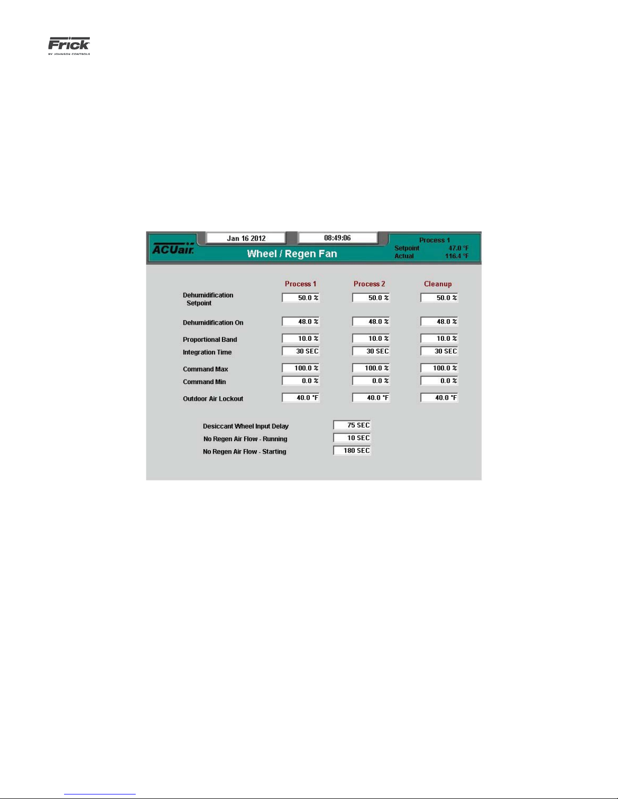
QUANTUM™ LX AcuAir™ CONTROL PANEL
liquid output must be deactivated before being
allowed to reactivate.
• Inter-Stage Delay - This delay specifi es the
minimum time that must expire between the activation of the fi rst and second stages. Hence,
even if the PI values raises rapidly, requiring the
second to activate, this time delay must expire
before stage 2 activation.
[Stage 2]
Wheel – Wheel/Regen Fan
OPERATION
090.510-O (SEPTEMBER 13)
Page 39
• Stage On - When the PI value rises above this
value, the digital liquid output will be activated.
• Minimum On Time - The minimum time a stage
liquid output will be activated before being allowed to deactivate.
• Minimum Off Time - The minimum time a stage
liquid output must be deactivated before being
allowed to reactivate.
SETPOINTS – Dehumidifi cation – Desiccant
The following setpoint boxes appear on this screen:
[Dehumidifi cation Setpoint]
• Process 1
• Process 2
• Cleanup
[Dehumidifi cation On]
• Process 1
• Process 2
• Cleanup
[Proportional Band]
• Process 1
• Process 2
• Cleanup
[Integration Time]
• Process 1
• Process 2
• Cleanup
[Command Max]
• Process 1
• Process 2
• Cleanup
[Command Min]
• Process 1
• Process 2
• Cleanup
[Outdoor Air Lockout]
• Process 1
• Process 2
• Cleanup
[Desiccant Wheel Input Delay]
[No Regen Air Flow – Running]
[No Regen Air Flow – Starting]
Page 40

090.510-O (SEPTEMBER 13)
Page 40
SETPOINTS – Dehumidifi cation – Desiccant Wheel – Regen Burner
QUANTUM™ LX AcuAir™ CONTROL PANEL
OPERATION
The desiccant control algorithm computes a value based on
the humidity, the post-wheel setpoint and the pre-wheel setpoint. The desiccant analog output value is selected as the
lowest of the three computations. The desiccant control will
operate when the outside air temperature is above a specifi ed
value, and the room humidity is also above a specifi ed value.
The following setpoint boxes appear on this screen:
[Setpoint]
• Pre-Wheel - The target temperature for air hitting the desiccant wheel.
• Post-Wheel - The target temperature for air
level the desiccant wheel.
[Proportional Band]
• Pre- Wheel
• Post-Wheel
[Integration Time]
• Pre-Wheel
• Post-Wheel
[Command Max]
• Pre-Wheel
• Post-Wheel
[Command Min]
• Pre-Wheel
• Post-Wheel
[Minimum On Time]
[Minimum Off Time]
[Burner Start Delay]
[Burner Ramp Delay]
[Burner Safeties Delay]
Page 41
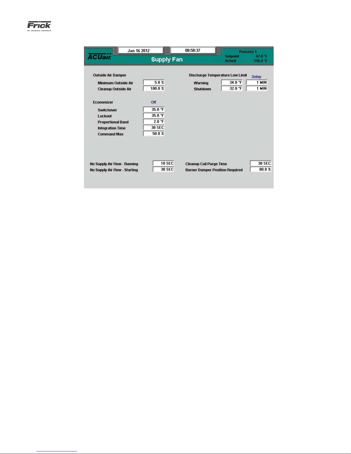
QUANTUM™ LX AcuAir™ CONTROL PANEL
OPERATION
SETPOINTS – Supply Fan
090.510-O (SEPTEMBER 13)
Page 41
The Damper Setpoints control the Outside Air Dampers and
the Economizer function of the unit. The Minimum Outside Air
Damper Position sets the minimum position that the Outside
Air Dampers can be closed to. The Cleanup Damper Position is
the position of the Outside Air Dampers during Cleanup.
In Process Mode if the Outside Air Temperature drops low
enough to assist with cooling in the room, the Economizer
Setpoints will open the Outside Air Dampers to allow cold air
from the outside to fl ow into the room. When Economizer is
enabled, the Outside Air Dampers are controlled by the Damper PID Command, which tries to move the Return Air Temperature toward the Process Control Setpoint. The Economizer
Proportional Band and Integration Time allows for the confi gu-
ration of the PID control.
The Economizer fl ag, displayed above the Economizer Set-
points, remains disabled while the Outside Air Temperature is
greater than the Economizer Switchover Setpoint. When the
Outside Air Temperature drops below the Economizer Switchover Setpoint, the Economizer fl ag is enabled and the Damper
PID Command begins to control the Outside Air Dampers. The
Damper PID Command continues to modulate the Outside Air
Dampers until the Outside Air Temperature rises above the
Economizer Switchover Setpoint plus the Economizer Differential Setpoint. At this point, the Economizer fl ag is again dis-
abled.
In Cleanup Mode while the Heating Purge Timer is on, the Outside Air Dampers remain at the Minimum Outside Air Damper
Position. As soon as the Heating Purge Timer has expired, the
Outside Air Dampers are moved to the Cleanup Damper Position where they remain for the duration of the Cleanup cycle.
The Exhaust Setpoints control the two exhaust fans on the unit.
The Exhaust Demand Value indicates how much air should be
exhausted from the unit. The Exhaust Demand Value is calculated by scaling the current Outside Air Damper Position
between the Minimum Outside Air Position and the Cleanup
Damper Position.
If the unit is running, and the Exhaust Demand Value moves
above the Stage #1 Start Setpoint, then Exhaust Fan #1 is
turned on. If the Exhaust Demand Value moves above the
Stage #2 Start Setpoint, then the Exhaust Fan #2 is turned
on. Likewise, when the Exhaust Demand Value drops below
the Stage #2 Start Setpoint, Exhaust Fan #2 is turned off. And
when the Exhaust Demand Value drops below the Stage #1
Start Setpoint, Exhaust Fan #1 is turned off.
Below is an example of Exhaust Fan Control:
Setpoints -
Minimum Outside Air Damper Position = 15%
Cleanup Damper Position = 90%
Stage #1 Start = 35%
Stage #2 Start = 70%
The Exhaust Demand Value is the current Outside Air Damper
Position scaled between 15% (Minimum Outside Air) and 100%
(Cleanup Damper Position). It can be calculated by using the
following equation. Below the equation are several possible
Outside Air Damper Positions, the corresponding Exhaust Demand Values and the Exhaust Fans' status based on the above
setpoints.
Page 42

090.510-O (SEPTEMBER 13)
Page 42
QUANTUM™ LX AcuAir™ CONTROL PANEL
OPERATION
Exhaust Demand Value = 100 * (Outside Air Damper Position Minimum Outside Air) / (Cleanup Damper Position - Minimum
Outside Air)
Outside Air
Damper
Position
Exhaust
Demand
Values
Stage #1 Stage #2
0% 0% Off Off
25% 13% Off Off
50% 47% On Off
75% 80% On On
100% 100% On On
The following setpoints appear on this screen:
[Outside Air Damper]
• Minimum Outside Air
• Cleanup Outside Air
[Economizer]
• Switchover
• Lockout
• Proportional Band
• Integration Time
• Command Max
[Discharge Temperature Low Limit]
• Warning
• Delay
• Shutdown
• Delay
[No Supply Airfl ow – Running]
[No Supply Airfl ow – Starting]
[Cleanup Coil Purge Time]
[Burner Damper Position Required]
Page 43
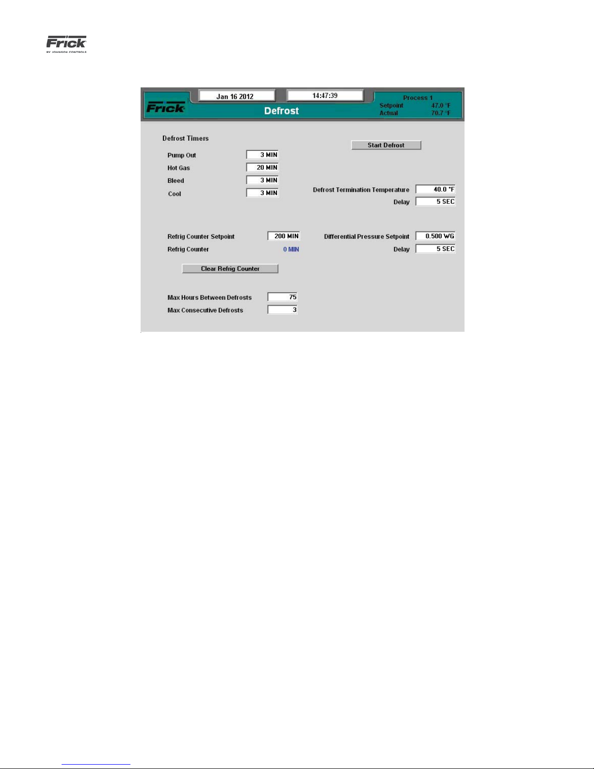
QUANTUM™ LX AcuAir™ CONTROL PANEL
OPERATION
SETPOINTS – Defrost – Defrost Setpoints
(Standard and Sequential Defrost with Hot Gas)
090.510-O (SEPTEMBER 13)
Page 43
The AcuAir® control system has been equipped with three
defrost options (the fi rst two are described on this page, the
third is described on the next page):
Standard Defrost - Standard defrost consists of four
stages: Pump Out, Hot Gas, Bleed, Cool. During the Pump
Out stage the suction remains open, and during the Hot
Gas stage both the suction and liquid are closed, while
the hot gas is opened. The Bleed stage opens the bleed
valve while closing the Hot Gas, Liquid and Suction valves.
Finally, the Cool stage permits the liquid and suction to
open, while the hot gas and bleed valves are closed. The
Defrost Confi guration page allows the user to specify the
duration for each of the defrost stages.
Sequential Defrost with Hot Gas - Utilizes the same
stages listed above. However each cooling coil is defrosted separately permitting the system to continue active
cooling via the coils not in defrost.
The following setpoint boxes appear on this screen:
Defrost Timers
[Pump Out] - The duration of the defrost Pump Out
stage.
[Hot Gas] – The duration of the defrost Hot Gas
stage.
to Refrig. Counter.
[Refrig Counter] The total time that cooling has been
active since the last defrost (not a setpoint).
[Defrost Termination Temperature] – This setpoint
specifi es the target temperature for Defrost stage
termination on Sequential Defrosts.
• Delay – The stabilization period for the Defrost
Termination Temperature input.
[Differential Pressure Setpoint] – This specifi es the
coil differential pressure at which defrost should be
initiated if the Defrost Pressure Initiation option is set
to Enabled.
• Delay – The stabilization period for the Differential Pressure input.
[Max Hours Between Defrosts] - If this duration is
exceeded, a control system warning will be generated.
[Max Consecutive Defrosts] – This specifi es the
number of consecutive defrosts that are permitted
before a control system warning is generated.
The following screen buttons have also been provided:
[Bleed] – The duration of the defrost Bleed stage.
[Cool] – The duration of the defrost Cool stage.
[Refrig Counter Setpoint] – When the Refrig Coun-
ter has reach the Refrig Counter Setpoint, a defrost
will be initiated if the Defrost Initiation has been set
[Clear Refrig Counter] – This button will require that the
Refrig. Counter be set to zero.
[Start Defrost] – This button permits the user to immediately initiate a defrost.
Page 44

090.510-O (SEPTEMBER 13)
Page 44
QUANTUM™ LX AcuAir™ CONTROL PANEL
OPERATION
SETPOINTS – Defrost – Defrost Setpoints
(Sequential Defrost)
The third defrost option is Sequential Defrost which consists
of only two stages, Defrost and Cool. During the Defrost stage
the suction is closed while the liquid remains open. The Max
Defrost Time setpoint specifi es how long the defrost must
continue if the Defrost Termination Temperature has not been
achieved. If this temperature is achieved, the stage will remain
active for the time specifi ed by the Defrost Continuation Time.
Then the Cool stage will take over which permits the suction
to open again. The duration of the cool stage can be specifi ed
for each coil. This defrost option also allows only one coil to
enter defrost at a time.
In addition to the setpoint boxes and descriptions shown on
the previous page, the following setpoint boxes appear on this
screen:
[Defrost Continuation] – The period of time that the
coil will continue in defrost after the Defrost Termination
Temperature has been achieved.
[Cool Stage 1, 2, 3, 4] – The period of time that a coil
must continue cooling after having completed the defrost
stage. When the Cool stage terminates, a subsequent coil
will enter defrost until all coils have been processed.
[Max Defrost Time] – The maximum amount of time that
a coil will be permitted to defrost if the Defrost Termination Temperature is not achieved.
Page 45

QUANTUM™ LX AcuAir™ CONTROL PANEL
OPERATION
SETPOINTS – Defrost – Defrost Schedule
090.510-O (SEPTEMBER 13)
Page 45
This screen shows the six different Defrost schedules that may
be setup on a seven day basis.
Each pair of text boxes allow the user to enter a time in hours
(0-23) and minutes (0-59). A defrost will be initiated for each
entry on the defrost schedule, provided that the Defrost Source
is set to initiate defrosts by the Defrost Schedule (see Defrost
Confi guration page).
An entry of 00:00 will void the time entry fi eld. If defrost is
required at midnight (00:00) use 00:01.
The following are descriptions of the setpoints:
Time Column - The time of day, in hours and minutes,
that you want to switch to the scheduled defrost control.
Page 46

090.510-O (SEPTEMBER 13)
Page 46
QUANTUM™ LX AcuAir™ CONTROL PANEL
OPERATION
SETPOINTS – Scheduling
DESCRIPTION: Scheduling allows the user to program up to
four different operating schedules for each day of the week.
This can be a great way to save energy. At night or on weekends and holidays, or even over lunch periods when room
doors are kept closed, or production is minimized, a higher
temperature can be set to reduce energy consumption.
This screen shows a time schedule. Up to four different modes
can be entered for each day of the week. The Schedule is only
effective if the Air Handler is set to automatic.
Notice that there are four columns of Hour/Minute entries,
each followed by an Operating mode selection. The available
selections are:
• Process 1
• Process 2
• Cleanup
• Off
Use the left most column (on the row for the day of the week
that you wish to schedule) to enter the time of day that you
would like the Air Handler to switch from it’s previous operating mode, into a new mode. When that time of day arrives, the
Air Handling Unit will be switched over to the scheduled mode.
This mode will then be the active running mode, and will continue to be the active mode until the time in the succeeding
column is reached. If the time in the next column is 00:00, it
will be skipped.
The Schedule must be activated to switch the presently active
mode to the Scheduling mode at the assigned time. An entry
of 00:00 will void the time entry fi eld. If a mode change is
required at midnight (00:00) use 00:01.
The following are descriptions of the setpoints:
Time Column - The time of day that you want to switch to
the Scheduled regulation setpoints of the active Process/
Cleanup control.
Mode Column - Set this to the Process/Cleanup Mode
that you want to run at the assigned time.
Page 47
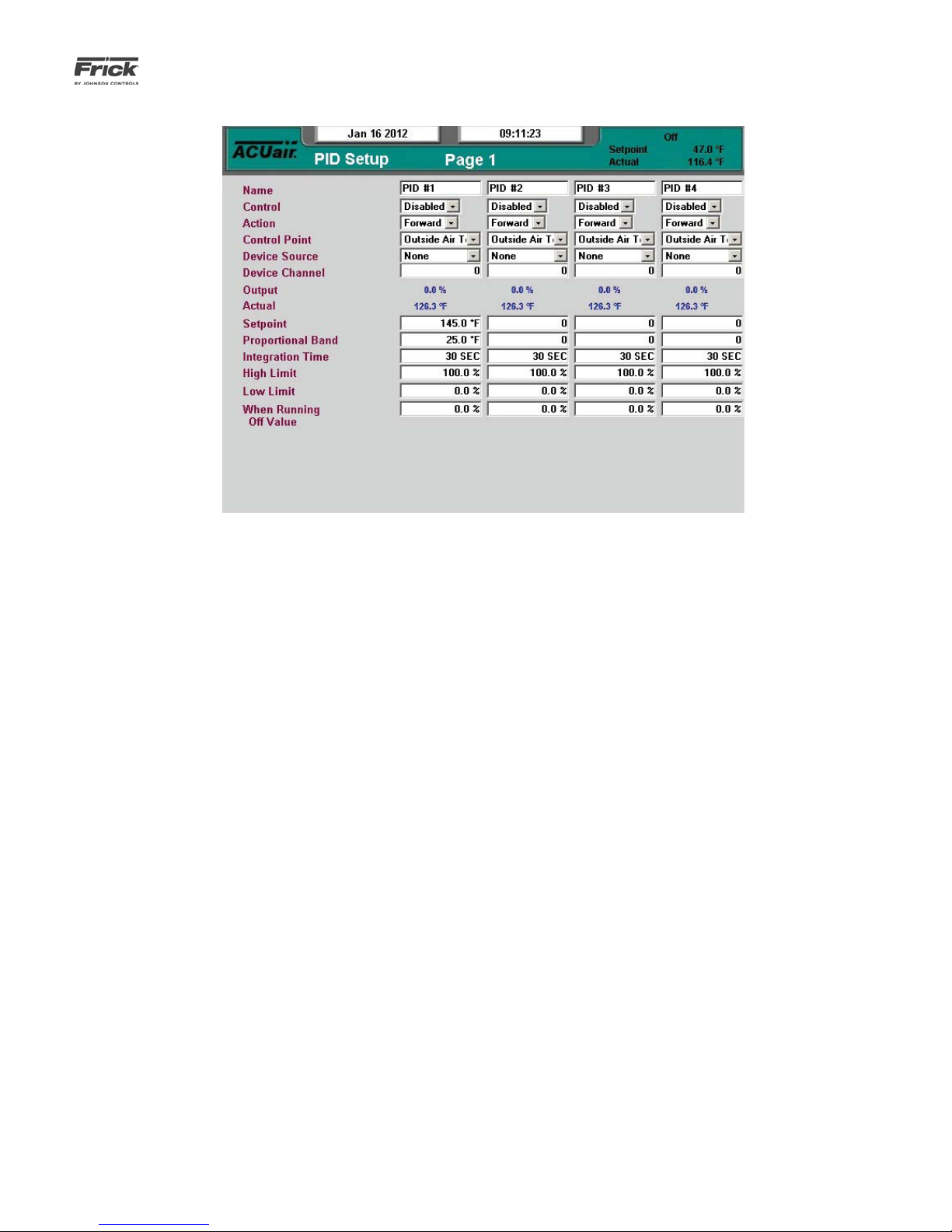
QUANTUM™ LX AcuAir™ CONTROL PANEL
OPERATION
SETPOINTS – PID Setup – Page 1
090.510-O (SEPTEMBER 13)
Page 47
DESCRIPTION: This screen allows the user to enter and view
the basic operating parameters related to PID control.
The following are the PID Setup screen selections:
[Name] - A user defi ned name can be entered here.
[Control] - A drop down menu is provided to select from
the following:
• Disabled - No PID control.
• Running - PID Control only controls when the
Air Handler is running.
• Active - PID control always active.
[Action] - A drop down menu is provided to select from
the following:
• Forward - Will increase the output at values
greater than the Control Setpoint.
• Reverse - Will increase the output at values less
than the Control Setpoint.
[Control Point] - A drop down menu is provided to select
from the following:
[Device Source] - A drop down menu is provided to select from the following:
• None
• Analog Board 1
• Analog Board 2
[Device Channel] - A setpoint entry box is provided to
select the analog board output channel that you wish to
use.
[Output] - The value of the Output signal as controlled by
the PID. This is not a setpoint value.
[Actual] - The Actual value of the input signal. This is not
a setpoint value.
[Setpoint] - Enter the value that you wish to control to.
[Proportional Band] – This setpoint determines the size
of a region either above or below the Control Setpoint.
Within this region, the output is governed by the PID
control, and assumes a value between high limit and low
limit. Outside of this region, the Proportional component
is either 100% or 0%. If the PID’s Action is Forward, the
Proportional Band extends above the Control Setpoint. If
the PID’s Action is Reverse, the Proportional Band extends
below the Control Setpoint.
• Outside Air Temperature
• Discharge Air Temperature
• Room Air Temperature
• Return Air Temperature
• Pre-Coil Air Temperature
• Coil Air Temperature
• Room Air Humidity
• Room Pressure
• Outside Air Damper
• Auxiliary Analog 1-20
[Integration Time] - This setpoint controls the infl uence
that the Integral component exerts on the PID Output
value. The Integral component works to push the Control
Input toward the Control Setpoint by tracking the difference between the Control Input and the Control Setpoint
over time.
[High Limit] - The highest value that the output can be.
[Low Limit] - The lowest value that the output can be.
Page 48

090.510-O (SEPTEMBER 13)
Page 48
QUANTUM™ LX AcuAir™ CONTROL PANEL
OPERATION
[When Running Off Value] - If the PID’s Control is When
Running, this value sets the value of the PID output when
the Air Handler is off.
Setting up a PID Channel
NOTE: The basic steps in setting up a device for PID con-
trol are:
Setup Input channel
• First, decide which physical input channel you
will be using. Note: If you wish to use an Auxiliary Analog channel, it will need to be completely
setup as its own channel before attempting the
remainder of this procedure.
Setup PID parameters
• From the Operating Status screen, access the
Menu. Select the [Setpoints] item. From the
Setpoints menu, select PID Setup. Finally, on the
PID Setup menu, select [Page 1].
• On the PID Setup screen, use the [Tab] key to
access the Analog channel that has already been
set up, in this case, channel 1.
• It is on this Setup screen that the remainder of
the PID parameters are entered. For a detailed
description of these parameters, refer to the
Overview to Tuning a PID Controller.
Note: Each device that is utilized for PID control must also
be properly calibrated.
Overview to Tuning a PID Controller
The purpose of this section is to give some basic guidelines
for tuning Proportional, Integral, and Differential gains of a
PID controller. To tune a PID controller, it would be advantageous to hook the system up to some test equipment to
allow you to record the appropriate variables. At the very
least, the appropriate data will have to be monitored and
recorded by hand from the system screen for subsequent
evaluation and possible spreadsheet graphing.
Proportional Band - The Proportional Band setpoint
translates the Proportional Gain into the units of the Control Input channel. When the control Input is at the Control
Setpoint, the Proportional component of the PID Output
will be 0%. As the Control Input moves through the Proportional Band, and away from the Control Setpoint, the
Proportional component will increase. If the Control Input is in the middle of the Proportional Band, the Proportional component value is 50%, and when the Control
Input reaches the outside of the Proportional Band, the
Proportional value will be 100%. The value of the Proportional component is calculated as the difference between
the Control Input and the Control Setpoint, divided by the
Proportional Band and then multiplied by 100.
Example:
Control Input: Outside Air Temperature
Control Setpoint: 100° F
Dead Band: 0° F
Proportional Band: 10° F
Action: Forward
Control Input Proportional Output
100° F 0%
102.5° F 25%
105° F 50%
108° F 80%
110° F 100%
112° F 100%
The value selected for the Proportional Band will be determined by the stability of the system, the accuracy required,
and the average output value, among other things. One way
to pick a starting value is to fi nd a range of allowable Control
Input values and then to select a Proportional Band so that the
Proportional value will reach 100% before the Control Input
moves outside of the allowable range.
After the initial value is entered for the Proportional Band,
watch the system to see how it reacts. If the PID output shows
too much oscillation, increasing the Proportional Band will
cause the control to react slower, which will dampen this oscillation. If the PID reacts too slowly, then decreasing the Proportional Band will make the control react faster.
Proportional Only Control - There will be certain applications
in which only proportional control is required for good performance. When this is the case, the Integration Time can simply
be set to zero, and the Proportional Band set to a desired
value.
Some advantages of only using Proportional control are that it
is generally more stable than Proportional and Integral control,
and its function is easier to understand. A disadvantage of only
using Proportional control is that the Control Input usually will
settle into a spot somewhere in the Proportional Band, and will
not move to the Control Setpoint. For instance, from the example shown above, if the Proportional Output averages 80%,
then the Control Input will remain at 108° F and will not go to
100° F. This may be acceptable in some applications. In certain
other cases the setpoint can be offset to move the Control
Input to the point it needs to be.
Integration Time - The Integral calculation in PID control uses
past performance to calculate a value for the PID output. It
does this by periodically adding a small value to the PID output to move the Control Input toward the Control Setpoint.
Eventually, the Integral component of the PID output will equal
the average PID output value as Control Input gets to the Control Setpoint, and the Proportional component goes to 0%.
When combined with the Integral calculation, the Proportional
component can be negative and its range becomes -100% to
+100%. If the Control Input moves above or below the Control
Setpoint, the Proportional control will prevent it from moving too far, and the Integral control will move it back to the
Page 49

QUANTUM™ LX AcuAir™ CONTROL PANEL
OPERATION
090.510-O (SEPTEMBER 13)
Page 49
setpoint.
Once the Proportional Gain is set, start with a large Integration
Time (180 seconds). Here again, you want to fi nd the range of
Integration Time that gives you reasonably fast performance,
without too much overshoot, and without too much oscillation.
SETPOINTS – PID Setup – Page 2
If the Control Input repeatedly overshoots the Control Setpoint, or oscillates too much, increasing the Integration Time
will slow the control. If the Control Input moves too slowly
toward the Control Setpoint, decreasing the Integration Time
will cause the control to react faster.
DESCRIPTION: This is the second PID screen, and allow the
end user to enter and view the basic operating parameters
related to PID control.
NOTE: See the description for PID Setup – Page 1, for information applicable to this screen.
Page 50
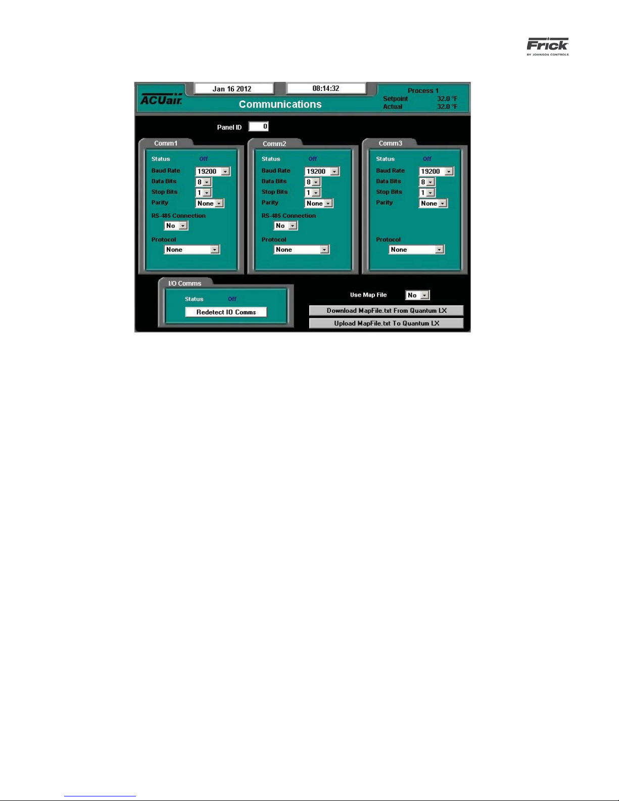
090.510-O (SEPTEMBER 13)
Page 50
QUANTUM™ LX AcuAir™ CONTROL PANEL
OPERATION
SETPOINTS – Communications
DESCRIPTION: This screen is used to set the Air Handler ID
number, and the parameters for each of the three communications channels, as well as to show the status of the internal I/O
board status.
The following setpoints are provided:
[Panel ID] - A number that is used by an external communications application to converse to individual Air Handling Units. On networked systems, this number must be
unique. Valid values are from 0 - 99.
Comm1
(Setup parameter defi nitions for Comm1, 2, and 3 are
identical) Communications related information for the
communications ports:
Status - Shows the current communications
status of the port. The possible messages are:
• Off - No communications are currently
taking place. NOTE: A delay of 15 seconds or more of inactive communications (time between valid responses)
will cause this message to display.
• Active - Valid communications are actively occurring.
• Failed - An invalid command was received by the port. This could be due
to a bad checksum value, a wiring issue, or hardware problem at either the
transmitting (client) or receiving (Quantum™ LX) end.
[Baud Rate] - The baud rate defi nes the speed
at which external communications can occur.
The higher the baud rate, the faster the communications. The faster the baud rate, the more
susceptible to external EMF. It is best to start out
using a lower baud rate, and increasing the value
only after verifying that communications errors
do not occur. If errors start to occur, decrease
the baud rate. A drop down menu is provided to
select from the following:
• 1200
• 2400
• 4800
• 9600
• 19200
• 38400
• 57600
• 115200
[Data Bits] - Determines the number of bits in a
transmitted data package. A pull down menu is
provided to select from the following:
• 7
• 8
[Stop Bits] - A bit(s) which signals the end of a
transmission on a serial line. A drop down menu
is provided to select from the following:
• 1
• 2
[Parity] - In communications, parity checking
refers to the use of parity bits to check that data
has been transmitted accurately. The parity bit is
added to every data unit (typically seven or eight
data bits) that are transmitted. The parity bit for
each unit is set so that all bytes have either an
odd number or an even number of set bits. Parity
Page 51

QUANTUM™ LX AcuAir™ CONTROL PANEL
OPERATION
090.510-O (SEPTEMBER 13)
Page 51
checking is the most basic form of error detection in communications. A drop down menu is
provided to select from the following:
• None
• Even
• Odd
[RS-485 Communications] - (Available for
Comms1 and Comms 2 only). This pull down
box allows the user to select whether or not the
communications will be through RS-485 hardware protocol or not. A drop down menu is provided to select from the following:
• Yes
• No
[Protocol] - A protocol is the special set of rules
that each end of a communications connection
use when they communicate. A drop down menu
is provided to select from the following Frick
recognized protocols:
• None
• Frick
• ModBus ASCII
• ModBus RTU
[I/O Comms] - A status indicator is provided to
show the current state of the internal communications of the I/O boards. The possible displayed
states are:
• Off - Loss of communications or intermittent communications failures to the
internal Quantum™ LX I/O boards.
• Active - Indicates that normal I/O communications are occurring.
• Failed - Loss of communications, a
shutdown message will be generated.
[Redetect IO Comms] - Select this key to detect all connected Analog and Digital boards. If a
board has been removed, a communication error
shutdown will be issued until this key is selected.
Reference the About screen to view what has
been detected.
[Use Map File] - Because the addressing scheme
between the Quantum™ version 2.3x and earlier
software and the Quantum™ LX version 3.0x and
later software is not the same, this utility was
created. The map fi le is a conversion utility that
can be used to allow a communications application that was previously written by the user
under the Quantum™ version 2.3x and earlier to
function properly with the LX by redirecting the
old addresses to the new LX addresses. A pull
down menu is provided to select from the following:
• No - Do not use map fi le, the user is
either not going to be using external
communications, or they will be writing
the communication application based
upon the LX addresses.
• Yes - The user has an application that
was previously written for the Quantum™ version 2.3x or earlier, and they
want to utilize the same code for the
LX.
Two keys are located at the bottom right hand side of the
screen. The following describes their function:
[Download MapFile.txt from Quantum™ LX] – With a
USB memory stick installed on the LX, pressing this key
will cause the MapFile.txt fi le to be downloaded from the
Quantum™ LX into the USB memory.
[Upload MapFile.txt to Quantum™ LX] – After the user
has modifi ed the MapFile.txt fi le to suit their needs, press-
ing this key will cause the fi le to be uploaded from the USB
memory back into the Quantum™ LX.
Page 52

090.510-O (SEPTEMBER 13)
Page 52
QUANTUM™ LX AcuAir™ CONTROL PANEL
OPERATION
SETPOINTS – Auxiliaries – Analog Inputs – Page 1
Drop down menu boxes are provided for the following :
Auxiliary Analogs 1 through 5
• Disabled – The auxiliary channel will not be
monitored for warnings or shutdowns.
• When Running - The auxiliary channel will be
monitored for warning and shutdown occurrences only when the unit is Running.
• Always - The auxiliary channel will be monitored
for warning and shutdown occurrences at all
times (Running or not).
The following setpoints are provided for each Auxiliary Analog
channel:
[Low Warning Setpoint] – This setpoint specifi es the Low
Warning alarm threshold. In the event that the associated
auxiliary analog input falls below this value for a period of
time exceeding the Low Warning Delay, an Auxiliary Low
Warning Alarm will be issued.
[Low Warning Delay] – This setpoint specifi es the period
of time that the associated auxiliary analog input must remain below the Low Warning Setpoint before an Auxiliary
Low Warning Alarm will be issued.
[Low Shutdown Setpoint] – This setpoint specifi es the
Low Shutdown alarm threshold. In the event that the associated auxiliary analog input falls below this value for
a period of time exceeding the Low Shutdown Delay, an
Auxiliary Low Shutdown Alarm will be issued, and the
AcuAir® controller will shut the unit down.
[Low Shutdown Delay] – This setpoint specifi es the peri-
od of time that the associated auxiliary analog input must
remain below the Low Shutdown Setpoint before an Auxiliary Shutdown Alarm will be issued.
[High Warning Setpoint] – This setpoint specifi es the
High Warning alarm threshold. In the event that the associated auxiliary analog input falls below this value for
a period of time exceeding the High Warning Delay, an
Auxiliary High Warning Alarm will be issued.
[High Warning Delay] – This setpoint specifi es the period
of time that the associated auxiliary analog input must remain above the High Warning Setpoint before an Auxiliary
High Warning Alarm will be issued.
[High Shutdown Setpoint] – This setpoint specifi es the
High Shutdown alarm threshold. In the event that the associated auxiliary analog input falls below this value for
a period of time exceeding the High Shutdown Delay, an
Auxiliary High Shutdown Alarm will be issued, and the
AcuAir® controller will shut the unit down.
[High Shutdown Delay] – This setpoint specifi es the
period of time that the associated auxiliary analog input
must remain above the High Shutdown Setpoint before an
Auxiliary Shutdown Alarm will be issued.
NOTE: If you wish to bypass the warnings and utilize only the
shutdown feature, then set all warning values identical to the
shutdown values.
Page 53

QUANTUM™ LX AcuAir™ CONTROL PANEL
OPERATION
SETPOINTS – Auxiliaries – Analog Inputs – Page 2
090.510-O (SEPTEMBER 13)
Page 53
Drop down menu boxes are provided for the following :
Auxiliary Analogs 6 through 10
• Disabled – The auxiliary channel will not be
monitored for warnings or shutdowns.
• When Running - The auxiliary channel will be
monitored for warning and shutdown occurrences only when the unit is Running.
• Always - The auxiliary channel will be monitored
for warning and shutdown occurrences at all
times (Running or not).
The following setpoints are provided for each Auxiliary Analog
channel:
[Low Warning Setpoint] – This setpoint specifi es the Low
Warning alarm threshold. In the event that the associated
auxiliary analog input falls below this value for a period of
time exceeding the Low Warning Delay, an Auxiliary Low
Warning Alarm will be issued.
[Low Warning Delay] – This setpoint specifi es the period
of time that the associated auxiliary analog input must remain below the Low Warning Setpoint before an Auxiliary
Low Warning Alarm will be issued.
[Low Shutdown Setpoint] – This setpoint specifi es the
Low Shutdown alarm threshold. In the event that the associated auxiliary analog input falls below this value for
a period of time exceeding the Low Shutdown Delay, an
Auxiliary Low Shutdown Alarm will be issued, and the
AcuAir® controller will shut the unit down.
[Low Shutdown Delay] – This setpoint specifi es the peri-
od of time that the associated auxiliary analog input must
remain below the Low Shutdown Setpoint before an Auxiliary Shutdown Alarm will be issued.
[High Warning Setpoint] – This setpoint specifi es the
High Warning alarm threshold. In the event that the associated auxiliary analog input falls below this value for
a period of time exceeding the High Warning Delay, an
Auxiliary High Warning Alarm will be issued.
[High Warning Delay] – This setpoint specifi es the period
of time that the associated auxiliary analog input must remain above the High Warning Setpoint before an Auxiliary
High Warning Alarm will be issued.
[High Shutdown Setpoint] – This setpoint specifi es the
High Shutdown alarm threshold. In the event that the associated auxiliary analog input falls below this value for
a period of time exceeding the High Shutdown Delay, an
Auxiliary High Shutdown Alarm will be issued, and the
AcuAir® controller will shut the unit down.
[High Shutdown Delay] – This setpoint specifi es the
period of time that the associated auxiliary analog input
must remain above the High Shutdown Setpoint before an
Auxiliary Shutdown Alarm will be issued.
NOTE: If you wish to bypass the warnings and utilize only the
shutdown feature, then set all warning values identical to the
shutdown values.
Page 54

090.510-O (SEPTEMBER 13)
Page 54
QUANTUM™ LX AcuAir™ CONTROL PANEL
OPERATION
SETPOINTS – Auxiliaries – Digital Inputs
Use this screen to setup an Auxiliary Digital Input that is to
be used to generate a warning or a shutdown whenever the
associated input is not active (off). As an example from the
screen shown above:
If Auxiliary Input 1 is set to Shutdown When Running, and the
Delay is set to 10 seconds, then whenever the device that is
physically attached to I/O Channel 15 (Digital Board 1) becomes
inactive (turns off) AND the unit is Running, then the delay
timer will start to count down. When the Delay times out, a
shutdown message is issued (Auxiliary Input 1 Shutdown), and
the unit will stop running.
As an example of how this screen could be used would be if
you had an airfl ow sensor that you confi gured to monitor a
fans operation. When the fan is energized, and began moving
air, the airfl ow switch would close and send a signal to the
controller on Digital Board 1, Channel 15. As long as this switch
remained closed, operation would be normal. However, if the
air fl ow switch opened, either because something happened to
the fan or the fan’s output (or even if the airfl ow sensor failed),
then the Delay timer associated with the channel would begin
to count down. If the airfl ow did not pick up before the Delay
counter timed out, then a Shutdown would be issued, and the
unit would stop.
A drop down menu box is provided for each of the eight possible Auxiliary Inputs:
[Activity]
• Disabled - The device will not be monitored for
warnings or shutdowns.
• Shutdown When Running - The device will be
monitored for shutdown occurrences only when
the unit is Running.
• Shutdown Always - The device will be monitored for shutdown occurrences all of the time.
• Warning When Running - The device will be
monitored for warning occurrences only when
the unit is Running.
• Warning Always - The device will be monitored
for warning occurrences all of the time.
[Delay] - This value specifi es the duration that the digital sig-
nal must remain off before a warning alarm is issued.
Page 55
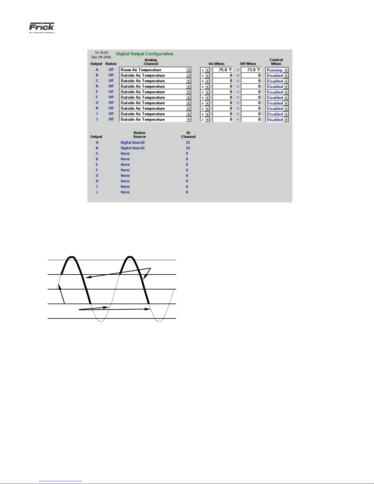
QUANTUM™ LX AcuAir™ CONTROL PANEL
74°
76°
Output is
energized
OPERATION
SETPOINTS – Auxiliaries – Digital Outputs
090.510-O (SEPTEMBER 13)
Page 55
Use this screen to setup and control an Auxiliary Digital Output
based upon the signal from an Analog Input. Such a use would
possibly be for cooling or heating control. The screen shown
above would allow for cooling, and a solenoid output could be
controlled to a cooling coil based upon the temperature of the
Room Air. The resulting temperature control would resemble
the following sine wave:
75°
73°
Output is
de-energized
72°
The bottom half of this screen shows the available Digital Outputs along with their Device Source and I/O Channels.
A drop down menu box is provided to select a channel to control from:
[Analog Channel] –
• Outside Air Temperature
• Discharge Air Temperature
• Room Air Temperature
• Return Air Temperature
• Pre-Coil Air Temperature
• Coil Air Temperature
• Room Air Humidity
• Room Pressure
• Differential Pressure
• Outside Air Damper
• Coil Temperature 1 - 4
• Pre-Wheel Regen Air Temperature
• Post-Wheel Regen Air Temperature
• Wheel Differential Pressure Switch
• Auxiliary Analog 1-20
[On When] – When operating in the (>) mode, the digital output will be de-energized when the analog signal
falls below the Off When value, and will remain off until
the input rises above the On When value. Similarly, when
operating in the (<) mode, the digital output will be deenergized when the input signal exceeds the Off When
value and re-energized when the analog signal falls below
On When value.
[Off When] - When operating in the (>) mode, the digital
output will be energized when the analog signal exceeds
the On When value, and will remain energized until the
input falls below the Off When value. Similarly, when operating in (<) mode, the digital output will be energized
when the input signal falls below the On When value, and
will remain in this state until the analog value exceeds Of
When value .
[Control When] –
• Disabled - The output will be disabled.
• Running - The output is controlled while Running.
• Always - The output is controlled always.
• Heating - The output is controlled while heating.
• Cooling - The output is controlled while cooling.
Page 56

090.510-O (SEPTEMBER 13)
Page 56
QUANTUM™ LX AcuAir™ CONTROL PANEL
OPERATION
SETPOINTS – Panel
DESCRIPTION: This screen is used to view and set basic Air
Handler operational values.
The following status display areas are provided:
Panel Temperature - The main processor board is
equipped with a temperature sensor. The panel has an
operational temperature range that is automatically maintained.
Panel Heater - A heating pad is mounted in the panel to
automatically maintain the internal temperature to allow
the electronics to function properly. The following Status
message and Setpoint boxes show the current state of the
Panel Heater:
• Off - If the panel temperature is greater than or
equal to this setpoint, the Panel Heater output is
turned off.
• On - If the panel temperature is less than or
equal to this setpoint, the Panel Heater output is
turned on.
The following setpoint boxes are provided:
[Power Fail Restart] - A drop-down box is provided:
• Disabled
• Enabled
An additional setpoint box is provided to enter the Power Fail
Restart time.
[Run Hours] – The number of hours that the unit has run.
Date - Set the following setpoint boxes to the current
date:
Time - Set the following three setpoint boxes to the current time:
[Hour] – Range is 0-23
[Minutes] – Range is 0 to 59
[Unit Name] - This setpoint box is provided to name each
unit with a unique identifi er.
Local Panel Units - The Local Panel Units settings on this
screen will only affect the way these values are locally
displayed. When communicating remotely to the panel,
these values will be shown based upon the way these values are set on the Session screen.
The following pull-down menus have been provided:
[Language] - You may choose from the following:
• English
[Pressure Units] - You may choose from the following
list:
• Kpaa
• Bar
• BarA
• PSIA
• PSIG/hg
[Temperature Units] - You may choose from the following list:
• Celsius
• Fahrenheit
[Date Format] - You may choose from the following list:
[Month] – Range is 1-12
[Day] – Range is 1-31
[Year] – Range is 2000-2050
• US - Month/Day/Year format
• Europe - Day/Month/Year format
Page 57

QUANTUM™ LX AcuAir™ CONTROL PANEL
OPERATION
CALIBRATION – Temperature
090.510-O (SEPTEMBER 13)
Page 57
DESCRIPTION: This screen is used to view and set the tem-
perature calibration values.
This screen should be used anytime a temperature sensor is
found to be out of calibration. The recommended practice for
adjusting the calibration reading is to fi rst determine which
sensor(s) need to be calibrated. Once this is determined, you
must know the actual reading that the sensor should be showing, This can be accomplished by comparing the displayed
reading shown here, with the actual value using a separate
measurement device, such as a Digital Volt Meter. Determine
the difference between what the screen reading for the sensor is, and what the reading of the separate device shows. As
an example, assume that the Outside Air Temperature on this
screen reads 120° F, but a separate device is showing a reading
of 123° F. Highlight the current value setpoint box for Outside
Air, and enter the value of 123. The new reading will now read
123, and should match your separate reading.
The following fi elds are provided:
[Outside Air]
• Current Value
• Offset
[Discharge Air]
• Current Value
• Offset
[Room Air]
[Return Air]
• Current Value
• Offset
[Pre-Coil Air]
• Current Value
• Offset
[Cool Air]
• Current Value
• Offset
[Pre-Wheel Regen Air]
• Current Value
• Offset
[Post-Wheel Regen Air]
• Current Value
• Offset
• Range Low
• Range High
[Pre-Wheel Air]
• Current Value
• Offset
• Current Value
• Offset
Page 58
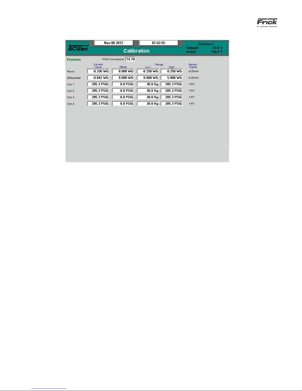
090.510-O (SEPTEMBER 13)
Page 58
QUANTUM™ LX AcuAir™ CONTROL PANEL
OPERATION
CALIBRATION – Pressure
DESCRIPTION: This screen is used to view and set pressure
values that are not shown on other screens.
This screen should be used anytime a sensor is found to be
out of calibration. The recommended practice for adjusting the
calibration reading is to fi rst determine which sensor(s) need
to be calibrated. Once this is determined, you must know the
actual reading that the sensor should be showing, This can be
accomplished by comparing the displayed reading shown here,
with the actual value using a separate measurement device,
such as a Digital Volt Meter. Determine the difference between
what the screen reading for the sensor is, and what the reading of the separate device shows. As an example, assume that
the Room Pressure on this screen reads 0.210 WG, but a separate device is showing a reading of 0.225 WG. Highlight the
current value setpoint box for Outside Air, and enter the value
of 0.120. The new reading will now read 0.120, and should
match your separate reading.
A screen key exists for each of the displayed analog readings.
This screen shows a pressure gauge and the current pressure
reading for:
[Room]
• Current Value
• Offset
• Low Range
• High Range
[Differential]
• Current Value
• Offset
• Low Range
• High Range
[Coil 1]
• Current Value
• Offset
• Low Range
• High Range
[Coil 2]
• Current Value
• Offset
• Low Range
• High Range
[Coil 3]
• Current Value
• Offset
• Low Range
• High Range
[Coil 4]
• Current Value
• Offset
• Low Range
• High Range
When pressure calibration is selected, the identifi cation of the
pressure measurement transducer and its settings are shown.
Select the [Calibration Setpoints] screen key to modify the
present calibration.
Page 59

QUANTUM™ LX AcuAir™ CONTROL PANEL
OPERATION
CALIBRATION – Miscellaneous
090.510-O (SEPTEMBER 13)
Page 59
DESCRIPTION: This screen is used to view and set miscella-
neous values that are not shown on other screens.
This screen should be used anytime a sensor is found to be
out of calibration. The recommended practice for adjusting the
calibration reading is to fi rst determine which sensor(s) need
to be calibrated. Once this is determined, you must know the
actual reading that the sensor should be showing, This can be
accomplished by comparing the displayed reading shown here,
with the actual value using a separate measurement device,
such as a Digital Volt Meter, or temperature probe, etc. Determine the difference between what the screen reading for the
sensor is, and what the reading of the separate device shows.
As an example, assume that the Room Air Humidity on this
screen reads 30%, but a separate device is showing a reading
of 40%. Highlight the setpoint box for Room Air Humidity, and
enter the value of 30. The new reading will now read 30, and
should match your separate reading.
A setpoint box exists for each of the displayed analog readings.
[Room Air Humidity]
• Current Value
• Offset
• Low Range
• High Range
[Outside Air Damper Position]
• Current Value
• Offset
• Low Range
• High Range
Page 60

090.510-O (SEPTEMBER 13)
Page 60
QUANTUM™ LX AcuAir™ CONTROL PANEL
OPERATION
CALIBRATION – Analog Outputs
DESCRIPTION: This screen is used to calibrate individual ana-
log outputs.
Use this screen if an analog output signal (channel) requires
calibration.
The QuantumTM LX analog outputs have a range of approximately zero to 25mA, but most devices that are controlled require a signal that varies between 4 and 20mA. To restrict the
analog outputs to the proper values, each of the outputs must
be calibrated before they can be used. Every output channel
has a Top End and a Bottom End value that are used for calibration. Both values can be set from 0% to 100%. The output channel’s maximum value is represented by 100% and its
minimum value is represented by 0%. To calibrate the channel,
the Top End percentage is decreased until the maximum output for the channel is limited to 20mA. In addition, the Bottom
End percentage is increased until the minimum output for the
channel is 4mA.
Below is a systematic procedure for calibrating one analog
output.
1. Confi gure the analog output channel for its intended
use. For example, if the channel is to be used for PID
control, enter the Device Source and Device Channel
of the selected analog output channel under one of
the PID columns on the PID Setup page.
2. Set a meter to read the channel output value in milliamps.
3. Go to the Analog Output Calibration page.
4. Select the Analog Board and the Channel Number for
the output that is being calibrated.
5. After the Analog Board and Channel Number are selected, the channel function will be displayed below
the Channel Number. If “Not Confi gured” is shown
here instead, the channel has not yet been assigned a
control function. Return to step 1 and setup the channel for the control task it is to perform.
6. Click on [Set Low End] and the value shown on the
meter should go to the channel low-end value.
7. Check that the “Delta For Changing Output Percentage” value is 10.00. If it is not, click on [Change Del-
ta] until it is displayed as 10.00.
8. If the channel output is greater than 4mA click on
[Decrement Output by Delta]. If the channel output is less than 4mA, click on [Increment Output by
Delta]. Use these keys to fi nd the output value clos-
est to 4mA.
9. Click on [Change Delta] once to decrease the “Delta
For Changing Output Percentage” value to 1.00.
10. Use the [Increment Output by Delta] and [Decre-
ment Output by Delta] buttons again to fi nd the
value closest to 4mA.
11. Repeat steps 9 and 10 for Delta values of 0.1 and 0.01
to bring the output value as close as possible to 4mA.
12. Click on [Set High End] and the value shown on the
meter should go to the channel high-end value.
13. Check that the “Delta For Changing Output Percentage” value is 10.00. If it is not, click on [Change Del-
ta] until it is displayed as 10.00.
14. If the channel output is greater than 20mA click on
[Decrement Output by Delta]. If the channel output
is less than 20mA, click on [Increment Output by
Delta]. Use these keys to fi nd the output value clos-
est to 20mA.
15. Click on [Change Delta] once to decrease the “Delta
For Changing Output Percentage” value to 1.00.
16. Use the [Increment Output by Delta] and [Decre-
ment Output by Delta] buttons to again fi nd the
value closest to 20mA.
17. Repeat steps 15 and 16 for Delta values of 0.1 and
0.01 to bring the output value as close as possible to
20mA.
NOTE: The analog output channel will return to its control task
either when another output channel is selected for calibration
or when the user goes to another screen.
Page 61

QUANTUM™ LX AcuAir™ CONTROL PANEL
OPERATION
CALIBRATION – Auxiliaries – Page 1
090.510-O (SEPTEMBER 13)
Page 61
DESCRIPTION: This screen is used to view and set the Auxil-
iary Analog calibration values.
This screen can be used to custom name each of the Auxiliary
Analog channels as well as performing calibration. To change
a name, simply click on the box that contains the name (at the
left side of the screen), and type a new name into the box,
then click [Submit].
A dropdown menu box exists for each of the displayed auxiliary readings.
• Current Value
• Offset
Page 62
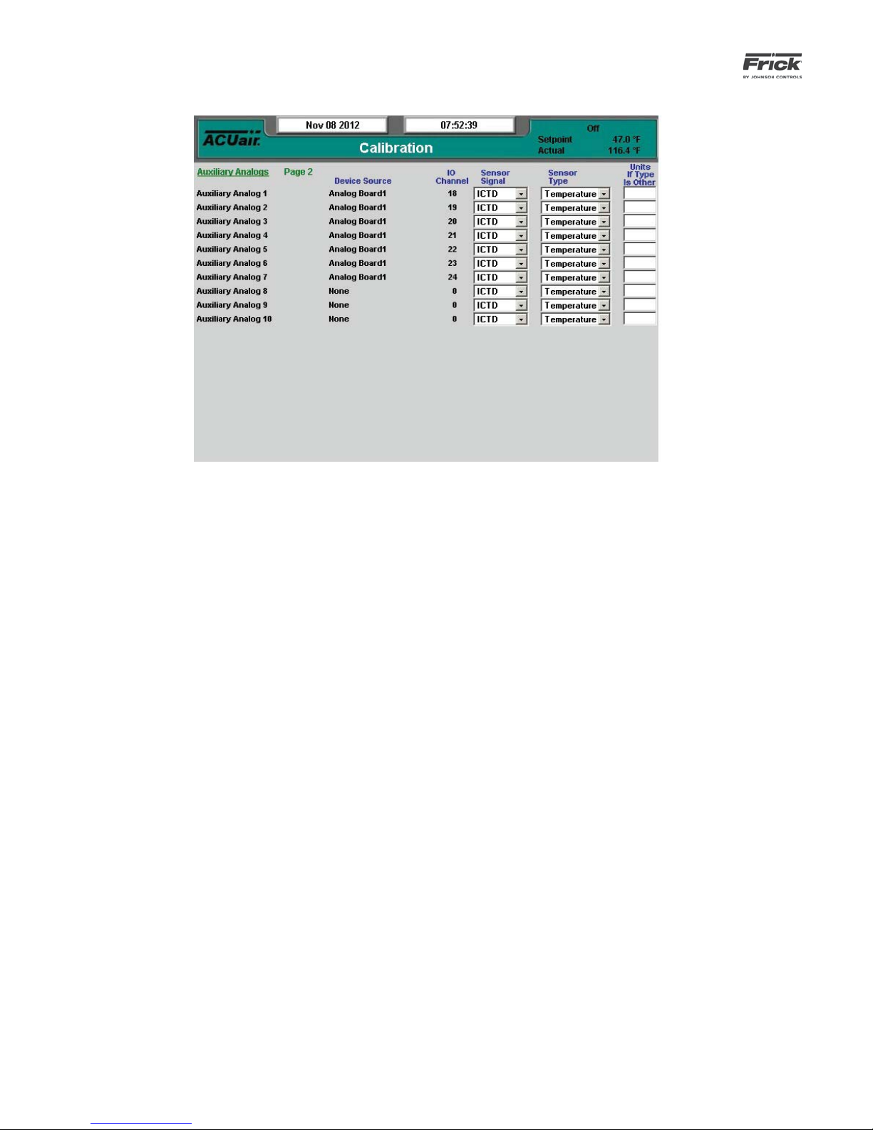
090.510-O (SEPTEMBER 13)
Page 62
QUANTUM™ LX AcuAir™ CONTROL PANEL
OPERATION
CALIBRATION – Auxiliaries – Page 2
DESCRIPTION: This screen is used to view and set the Auxil-
iary Analog calibration values.
This screen will show any custom named auxiliaries from Page
1 at the left side of the screen. Use this screen to set the Sensor Signal, Sensor Type, and to change the units if set to Other.
A dropdown menu box exists for each of the displayed auxiliary readings:
Sensor Signal
• None
• 0-5V
• 1-5V
• 4-20mA
• Pot. (Potentiometer)
• ICTD
• RTD
• CT
• RPM
• Vibration
• 0-10V
• +/-5V
• 2-10V
Sensor Type
• None
• Pressure
• Temperature
• Other
Units if Type is Other
Page 63
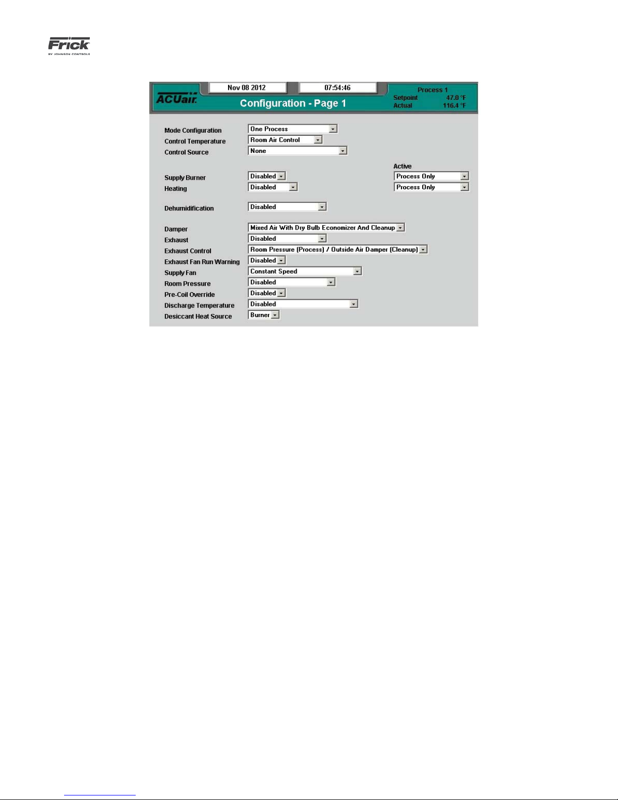
QUANTUM™ LX AcuAir™ CONTROL PANEL
OPERATION
CONFIGURATION – Control – Page 1
090.510-O (SEPTEMBER 13)
Page 63
The following drop down menu boxes are provided.
[Mode Confi guration]
• One Process
• One Process and Cleanup
• Two Process
• Two Process and Cleanup
[Control Temperature]
• Room Air Control
• Return Air Control
• Discharge Air Control
[Control Source]
• None
• Remote Switch
• Schedule
• Remote Switch and Schedule
[Supply Burner]
• Disabled
• Direct
• Indirect
[Supply Burner Active]
• Process Only
• Cleanup Only
• Process and Cleanup
[Heating]
• Disabled
• Single Stage
• Two Stage
[Heating Active]
• Process Only
• Cleanup Only
• Process and Cleanup
[Dehumidifi cation]
• Disabled
• Cooling
• Desiccant
• Desiccant and Cooling
[Damper]
• Mixed Air With Dry Bulb Economizer and Cleanup
• 100% Outside Air
[Exhaust]
• Disabled
• Single Stage
• Two Stage
• VFD and Single Speed
[Exhaust Control] – The following options permit the exhaust fans to control exclusively off Room Pressure, or
exclusively off the Outside Air Damper. The Outside Air
Damper Always option will control the exhaust fans off
Room Pressure during Process modes, and off the Outside
Air Damper during Cleanup mode.
• Room Pressure (Process) / Outside Air Damper
(Cleanup)
• Room Pressure Always
• Outside Air Damper Always
[Exhaust Fan Run Warning] - This feature supplies a
digital input which will trigger a warning if it remains de-
Page 64

090.510-O (SEPTEMBER 13)
Page 64
QUANTUM™ LX AcuAir™ CONTROL PANEL
OPERATION
energized beyond a specifi ed period of time. This safety
is only active when the exhaust fans are running, and the
Exhaust Fan Run Warning is set to Enabled.
• Disabled
• Enabled
[Supply Fan] - This option is intended to be used in colder climates where outside air is found to be cold and dry.
When this occurs, it is possible to drop the supply fan
speed and using less air to dry out a room after washdown. The supply fan speed will be reduced proportionally as the outside air temperature falls below a specifi ed
temperature. If the temperature continues to fall, a second set point designates the temperature at which the
supply fan speed will be set to the Base speed, preventing
any further speed reductions.
• Constant Air Volume
• Variable Speed – Mode
• Variable Speed – Temp. and Mode - This setting
enables the feature described above, which permits the supply fan speed to be reduced during
Cleanup only, under low temperature conditions.
[Room Pressure]
• Disabled
• Room Pressure High Limit
[Pre-Coil Override]
• Disabled
• Enabled
[Discharge Temperature]
• Disabled
• Discharge Temperature Low Limit
[Desiccant Heat Source] – This feature permits the usage of steam to heat the desiccant wheel instead of a gas
fi red burner. This control operates in a fashion similar to
the Burner heat source, except that several warnings are
not used, and ramping is not required.
• Burner
• Steam
Page 65

QUANTUM™ LX AcuAir™ CONTROL PANEL
OPERATION
CONFIGURATION – Control – Page 2
090.510-O (SEPTEMBER 13)
Page 65
The following drop down menu boxes are provided.
Miscellaneous
[Defrost]
• Disabled
• Standard Defrost – A defrost of all coils simultaneously in four stages: Pump Out, Hot
Gas, Bleed, Cool.
• Standard Defrost Sequential Defrost with
Hot Gas – A defrost of each coil sequentially
in four stages: Pump Out, Hot Gas, Bleed,
Cool.
• Sequential Defrost - A defrost is two stages by switching only the suction valve.
[Defrost Initiation]
• Basic – Defrosts initiated by the Defrost input or by user request ( Setpoints -> Defrost
-> Defrost Setpoints).
• Time of Day -- Defrosts initiated by the
defrost schedule. Setpoints -> Defrost ->
Defrost Schedule.
• Refrig Counter – Defrosts initiated when
the Refrig Counted exceeds the Refrig
Counter Setpoint ( Setpoints -> Defrost ->
Defrost Setpoints).
• Time with Refrig Override -- Defrosts
initiated by the Defrost schedule provided
the Refrig Counter has exceeded the Refrig
Counter Setpoint ( Setpoints -> Defrost ->
Defrost Setpoints).
[Differential Pressure Initiation]
• Disabled
• Enabled
[Air Defrost]
• Disabled
• Enabled
[Smoke Detector]
• Disabled
• Enabled
Cooling - This feature allows the user to further customize the usage of multiple stages of cooling. Each stage is
equipped with a set point specifying the mode or modes
under which each stage is permitted to be active. The
usage of this control should be carefully coordinated with
Stage On Setpoints found under Setpoints > Temperature
> Cooling to be sure desired results are achieved.
[Confi guration]
• Disabled
• Single Stage
• Two Stage
• Three Stage
• Four Stage
• Flooded – Single Stage
• Flooded – Two Stage
[Active]
• Process Only
Page 66

090.510-O (SEPTEMBER 13)
Page 66
QUANTUM™ LX AcuAir™ CONTROL PANEL
OPERATION
• Cleanup Only
• Process and Cleanup
[Suction]
• Cooling Always
• Cooling With Liquid
• Flooded Coil
[Suction Valve]
• Forward
• Reverse
[Cooling Valve]
• Forward
• Reverse
[Mode Active – Stage 1]
• Process Only
• Cleanup Only
• Process and Cleanup
[Mode Active – Stage 2]
• Process Only
• Cleanup Only
• Process and Cleanup
[Mode Active – Stage 3]
• Cleanup Only
• Process and Cleanup
Pre-Wheel Cooling – This feature allows the user to
confi gure a one or two stage cooling coil which is typi-
cally placed before the desiccant wheel to regulate the
air temperature for optimum dehumidifi cation. The usage
of this control should be coordinated with the Stage On
Setpoints found under Setpoints > Temperature > PreWheel Cooling.
[Confi guration]
• Disabled
• Single Stage
• Two Stage
[Active]
• Process Only
• Cleanup Only
• Process and Cleanup
[Suction]
• Cooling Always
• Cooling With Liquid
[Suction Valve]
• Forward
• Reverse
• Process Only
• Cleanup Only
• Process and Cleanup
[Mode Active – Stage 4]
• Process Only
[Cooling Valve]
• Forward
• Reverse
Page 67
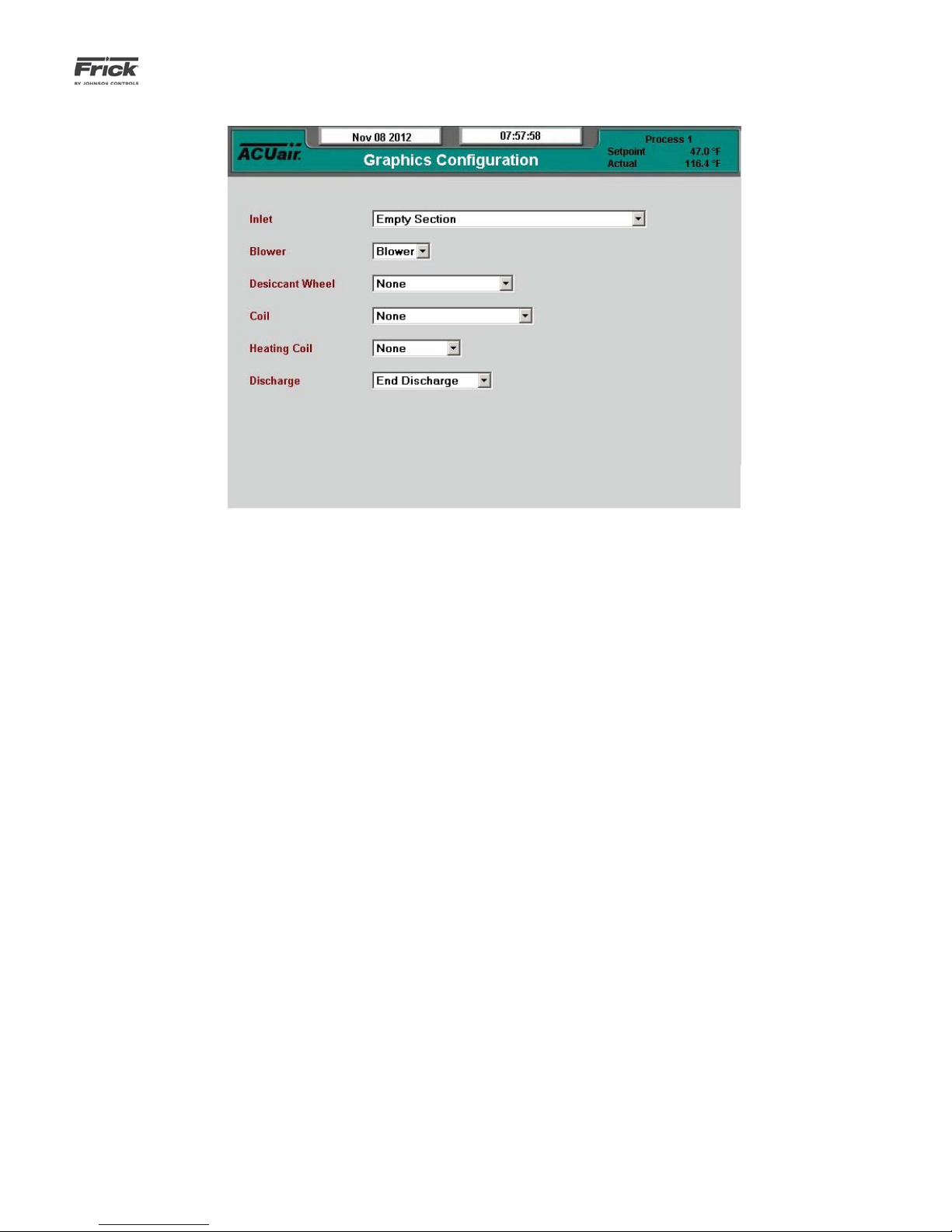
QUANTUM™ LX AcuAir™ CONTROL PANEL
OPERATION
CONFIGURATION – Graphics
090.510-O (SEPTEMBER 13)
Page 67
At least User Level 2 must be set to access this screen. Used
to confi gure the appearance of the pictorial graphic shown on
the Home screen. The setup of this screen is not required for
actual unit operation.
The following drop down menus are provided:
Inlet
• Empty Section
• DF Burner
• DF Burner, Exhaust, End Return
• Exhaust, End Return
• DF Burner, End Return
• End Return
• DF Burner, Smartheat, Exhaust, End Return
• DF Burner, Smartheat, End Return
• DF Burner, Exhaust, Bottom Return
• Exhaust, Bottom Return
• DF Burner, Bottom Return
• Bottom Return
• DF Burner, Smartheat, Exhaust, Bottom Return
• DF Burner, Smartheat, Bottom Return
Blower
• Blower
Desiccant Wheel
• None
• Wheel Module/Regen
Coil
• None
• 1-4 Coil
• 1-4 Coil, Integral Re-heat
• 1-3 Coil
• 1-3 Coil, Integral Re-Heat
Heating Coil
• None
• Heating Coil
Discharge
• End Discharge
• Bottom Discharge
Page 68

090.510-O (SEPTEMBER 13)
Page 68
QUANTUM™ LX AcuAir™ CONTROL PANEL
OPERATION
CONFIGURATION – Ethernet
DESCRIPTION: This screen is used to view and set basic Eth-
ernet operational values. It is from this screen that all internet
and e-mail based operating characteristics are set. NOTE: In
order to connect to the Internet, a valid Internet account and
connection must be used.
NOTE: User Level 1 or above must be set to access this
screen.
The following fi elds are provided:
IP Data:
[Address Type] - The following drop down menu is
provided:
• Fixed (Static)
• DHCP (Dynamic)
This should be set by the network or LAN administrator.
[IP Address] - Four setpoint boxes are provided here.
The network or LAN administrator will enter the numerical IP address for this specifi c Air Handler unit.
[Gateway Address] - Four setpoint boxes are provided here. The network or LAN administrator will
enter the numerical Gateway address.
[Subnet Mask] – Like IP addresses, a subnet mask
contains four bytes (32 bits) and is often written using the same "dotted-decimal" notation. A subnet
mask neither works like an IP address, nor does it exist independently from them. Instead, subnet masks
accompany an IP address and the two values work
together.
Applying the subnet mask to an IP address splits the
address into two parts, an "extended network address" and a host address.
For a subnet mask to be valid, its leftmost bits must
be set to '1'. Conversely, the rightmost bits in a valid
subnet mask must be set to '0', not '1'.
All valid subnet masks contain two parts: the left side
with all mask bits set to '1' (the extended network
portion) and the right side with all bits set to '0' (the
host portion).
[Web Server Port] - One setpoint box is provided
here. The network or LAN administrator will enter the
numerical address for this Web port.
Email Data
[Email Notifi cation On Alarm or Shutdown] - For
the E-mail notifi cation feature to work, it must be en-
abled (it is disabled as a default). The following drop
down menu is provided:
• Disabled
• Enabled
[Local Email Address] - Use this setpoint box to enter a valid E-mail address.
[Alias Name For Local Email Address] - Enter here a
custom name to identify more clearly the local Email
address. When a message is sent to all recipients,
this is the name that will appear in the Email FROM
column.
[Subject] - Enter here a custom subject that you
would like to have appear when a message failure is
sent. When a message is sent to all recipients, this
is the wording that will appear in the Email SUBJECT
Page 69

QUANTUM™ LX AcuAir™ CONTROL PANEL
OPERATION
090.510-O (SEPTEMBER 13)
Page 69
column.
[SMTP Server Name OR IP Address] - SMTP stands
for Simple Mail Transfer Protocol. This should be set
by the network or LAN administrator.
[SMTP Server Port Number] - This value is in almost all cases going to be 25. This should be set by
the network or LAN administrator.
CONFIGURATION – Security
[Comma-Delimited List of Email Recipients] - This
is simply the list of the Email addresses that you
would like to have any messages sent to.
Refer to the Communications Manual (090.510-CS) for additional information.
DESCRIPTION: This screen allows the user/supervisor to set
the various levels of password protection. The Security screen
shown above can only be modifi ed at the Quantum™ LX con-
trol panel via the keypad.
The various levels are:
• Level 0 - Also known as the BASIC level. This level is
not shown on the Security screen, as it is the lowest
level of system access, and as such, does not require
a password to activate. This is the default level, and
provides access to only the very basics of machine
operation.
• Level 1 - Also known as the ADVANCED level. This
requires a password to set. Only those users who are
authorized with the password may enter this level.
It provides greater access than Level 0 (BASIC). The
valid entry range is zero (0) to 5000. The factory default value for this password is 10 (ten).
• Level 2 - Also known as the SERVICE level. This requires a password to set. Only those users who are
authorized with the password may enter this level.
It provides greater access than Level 1. The factory
default value for this password is 20 (twenty).
To set the password protection for the each level, use the
keypad to highlight the box beside the level that you wish to
change. Set the level to either zero (0) or one (1), and enter
the appropriate password for that level in the next box. The
valid range for password entry is -999999 to 999999.
NOTE: It is highly recommended that the supervisor documents this password and stores it in a safe place. If the password is ever forgotten, it can only be corrected by calling the
factory.
Page 70
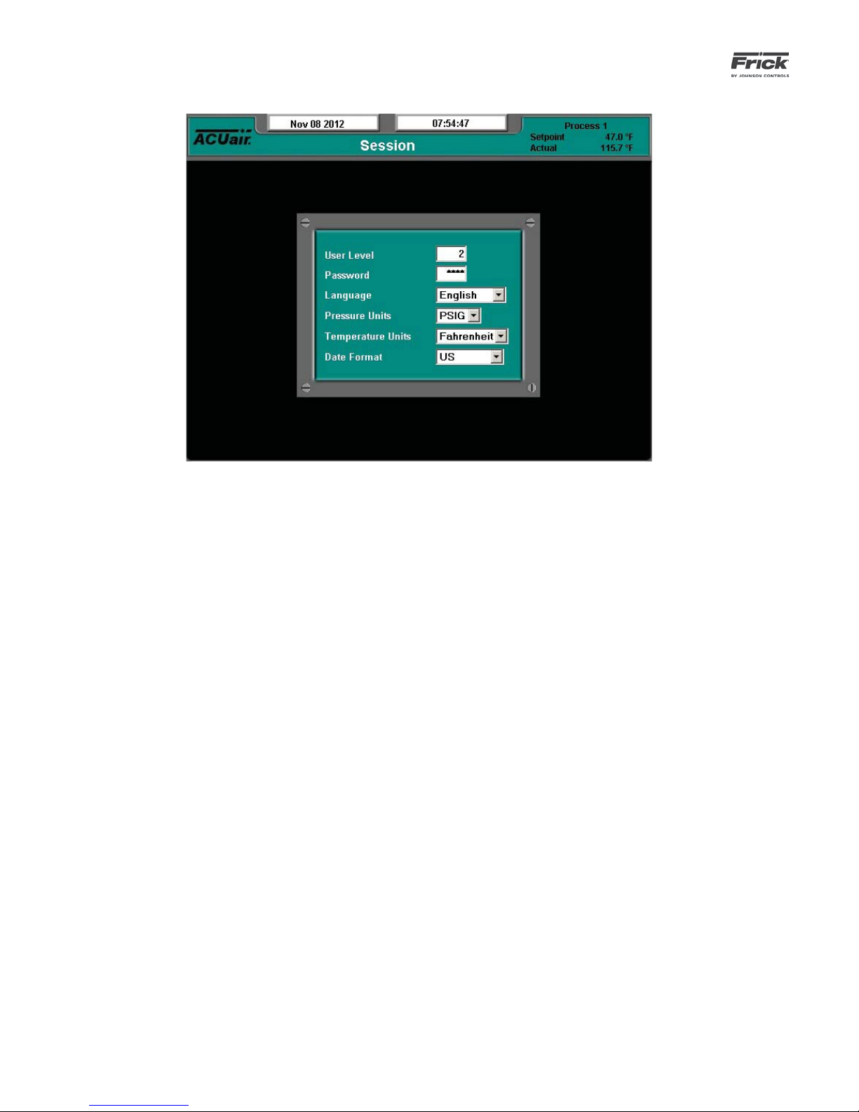
090.510-O (SEPTEMBER 13)
Page 70
QUANTUM™ LX AcuAir™ CONTROL PANEL
OPERATION
SESSION
DESCRIPTION: This screen allows the user/supervisor to ac-
cess the various available user levels. This is also where the
user can select the language, pressure units, temperature units
and date format.
The following Setpoints may be changed:
[User Level] - Any one of three possible levels may be accessed here. Level one (0) is also referred to as the BASIC
level, and requires no password. Level one (1) is referred
to as ADVANCED, and requires a password. Level one (2) is
referred to as SERVICE, and requires a password.
[Password] - A password has previously been assigned
to each user level by the supervisor. The user must match
the password for the particular level that they wish to access. The following factory default passwords have been
provided:
• Level 0 (Basic) – No password required
• Level 1 (Advanced) – 10
• Level 2 (Service) - 20
The following drop down menus have been provided:
Language - You may choose from the following list:
• English
[Pressure Units] - You may choose from the following list:
• Kpaa
• Bar
• BarA
• PSIA
• PSIG/hg
[Temperature Units] - You may choose from the following list:
• Celsius
• Fahrenheit
[Date Format] - You may choose from the following list:
• US - Month/Day/Year format
• Europe - Day/Month/Year format
Page 71

QUANTUM™ LX AcuAir™ CONTROL PANEL
OPERATION
SERVICE - Digital
090.510-O (SEPTEMBER 13)
Page 71
DESCRIPTION: This screen allows the technician to view the
status of all installed digital board inputs and outputs. An OFF
status indicates that the associated input or output is not en-
SERVICE – Analog
ergized. An ON status indicates that the associated input or
output is energized.
DESCRIPTION: This screen allows the technician to view the
status of all the analog board inputs and outputs. The top section of this screen shows the analog inputs. A value displayed
next to each available channel indicates the DC voltage that
is present as an input. The lower half of the screen shows the
analog outputs. A value displayed next to each available channel indicates the DC voltage that is present as an output.
Page 72

090.510-O (SEPTEMBER 13)
Page 72
QUANTUM™ LX AcuAir™ CONTROL PANEL
OPERATION
SERVICE – Communications Log
DESCRIPTION: This screen allows the technician to view the
status of all communications ports.
The following user selectable buttons are provided:
• [Show Comm1]
• [Show Comm2]
• [Show Comm3]
• [Show Comm4]
This screen allows the technician to view all of the communications information that the Quantum™ LX is receiving and
transmitting, one port at a time. Simply select the button at
the upper right side of the screen that corresponds to the port
that you wish to view. The selected port name (in this case
Comm4) will appear in the upper left side of the screen.
Each time a new command is sent or received, the screen will
need to be refreshed by selecting the [Show CommX] button
(where X is replaced with the comm port number).
This screen will display all data that is coming through the
selected Communications (Comm) port. The top line of data
is the most recent activity. At the left of each line, you should
see whether the data is IN or OUT (Receive or Send), and
the actual data (in Hexadecimal format). This information can
be used to compare against the data being sent and received
at the other end of the communications link, to verify proper
operation.
Page 73

QUANTUM™ LX AcuAir™ CONTROL PANEL
OPERATION
SERVICE – Communications Loop-Back Test
090.510-O (SEPTEMBER 13)
Page 73
Refer to the Communications Manual (090.510-CS) for specifi c
information about this test.
SERVICE – Diagnostics
Page 74
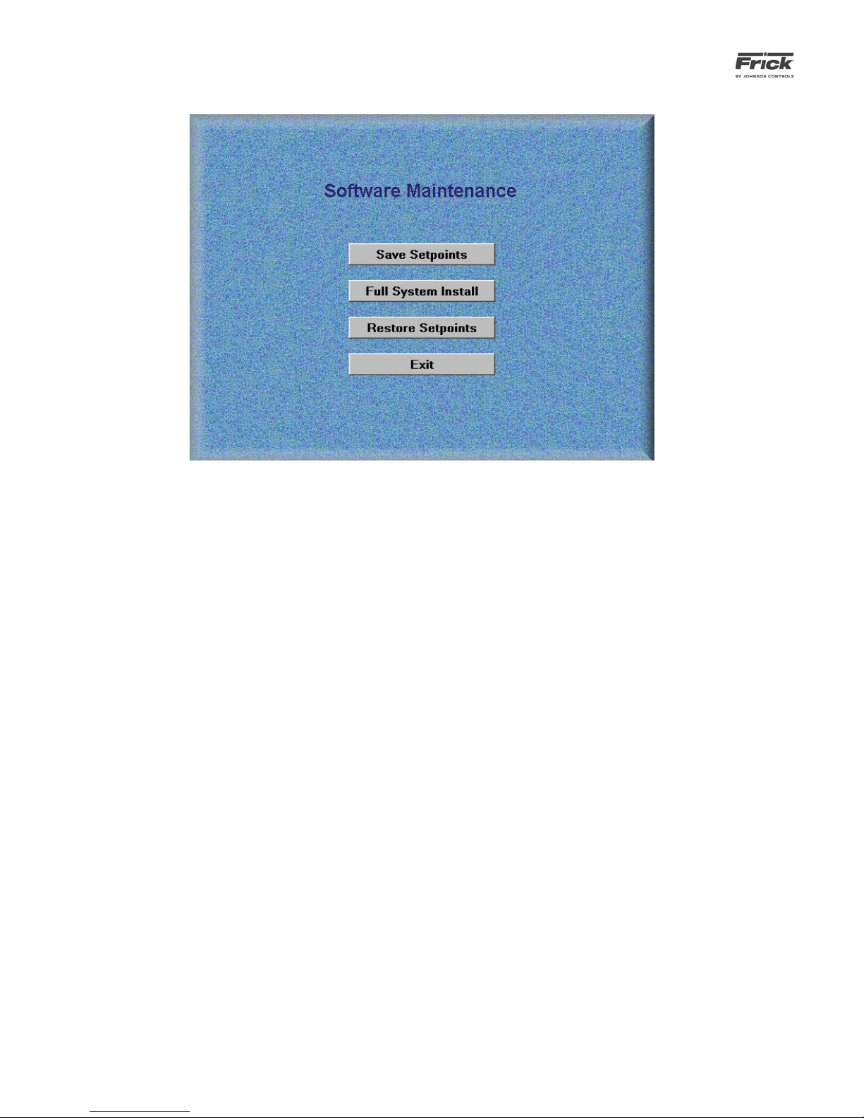
090.510-O (SEPTEMBER 13)
Page 74
QUANTUM™ LX AcuAir™ CONTROL PANEL
OPERATION
SERVICE – Software Maintenance
DESCRIPTION: This screen allows the technician to perform
system software maintenance.
The following selections have been provided:
1) Save Setpoints - Use this option to save all setpoints
and custom text to a fl ash card as a form of backup):
• Ensure that all setpoint values have been docu-
mented as a safety precaution.
• Click on the [Save Setpoints] button.
• The wording on the [Save Setpoints] button will
be replaced with Please Wait…
• When fi nished, the [Save Setpoints] button will
return to normal.
• A new window will pop up with a link to down-
load the recently saved setpoints. Right –click on
the link, and select “Save As”. The browser will
then allow the user to select a directory location.
NOTE: Do not change the name of the fi le or else
future setpoint restoration operations may fail.
2) Full System Install - Use this option to install the entire operating system. This function will not overwrite
any setpoints or custom text that may have previously been setup:
• Ensure that all setpoint values have been docu-
mented as a safety precaution.
• A new window will appear requesting the user
to select a fi le to upload. The “Browse” button
permits the user to locate the fi le by navigating
through the system’s directory structure. Once
the System Install File has been located, click
“Upload File” to allow the process to continue.
• The wording on the [Full System Install] button
will be replaced with Please Wait…
• When fi nished, the [Full System Install] button
will return to normal.
3) Restore Setpoints - Use this option to restore all
setpoints and custom text from a fl ash card to the
Quantum™. This would be useful in the event that the
original setpoints would need to be reloaded:
• Ensure that all setpoint values have been docu-
mented as a safety precaution.
• Click on the [Restore Setpoints] button.
• The wording on the [Restore Setpoints] button
will be replaced with Please Wait…
• When fi nished, the [Restore Setpoints] button
will return to normal.
4) Exit - Use this selection to leave this screen, the panel
will reboot and return to the Operating Status screen.
• Click on the [Full System Install] button.
Page 75
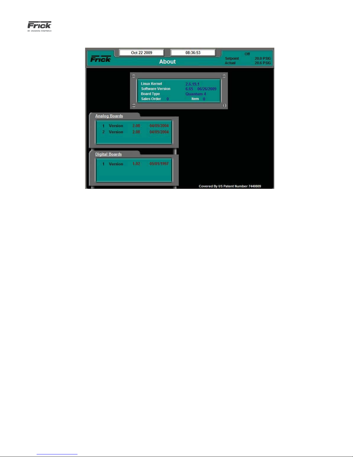
QUANTUM™ LX AcuAir™ CONTROL PANEL
OPERATION
ABOUT
090.510-O (SEPTEMBER 13)
Page 75
DESCRIPTION: The About screen shows all microprocessor-
based circuit boards that have been detected by the Quantum™ LX, as well other related software information.
The following information is shown here:
Linux Kernel - The Quantum™ LX controller runs on a
Linux operating system (rather than Microsoft Windows).
This is the software version number for the main Linux
Kernel.
York Quantum Software - This is the version of the software program that does the actual control of the Air Handler. It runs in the Linux environment.
Sales Order - A six digit numerical value that has been
assigned to a specifi c Air Handler package by Frick Com-
pany. It is very important to have this number available
when calling the factory for assistance or parts ordering.
Item - This is actually an extension of the Sales Order
number. It would potentially be used for a multiple Air
Handler site, where the same Sales Order number was
assigned for all Air Handlers. The Item Number would be
different for each unit.
Analog Boards - Displays the analog board that were detected through communications at the last power up. If
board were detected, the software version of the program
running on that board (with date of the software) will be
shown.
Digital Boards - Shows all digital boards that were detected through communications at the last power up. If
boards were detected, the software version of the program running on that board (with date of the software)
will be shown.
Page 76

090.510-O (SEPTEMBER 13)
Page 76
QUANTUM™ LX AcuAir™ CONTROL PANEL
OPERATION
Page 77

QUANTUM™ LX AcuAir™ CONTROL PANEL
OPERATION
SECTION 4
ALARMS/SHUTDOWNS MESSAGES
090.510-O (SEPTEMBER 13)
Page 77
The following is the alphabetical listing of all the possible
Warnings and Shutdowns:
Analog Board 1 Communications Shutdown – The Quantum™ LX controller is no longer able to communicate to Analog Board 1.
Auxiliary Input 1 Shutdown – A unit Shutdown has occurred
and message issued because the input value from the Auxiliary
Input 1 channel has been lost for a period of time greater than
its Delay setpoint. To view the screen containing these setpoints: Menu > Setpoints > Auxiliaries > Digital Inputs.
Auxiliary Input 1 Warning - A unit Warning message was
issued because the input value to the Auxiliary Input 1 channel has been lost for a period of time greater than its Delay
setpoint. To view the screen containing these setpoints: Menu
> Setpoints > Auxiliaries > Digital Inputs.
Auxiliary Input 2 Shutdown - A unit Shutdown has occurred
and message issued because the input value from the Auxiliary
Input 2 channel has been lost for a period of time greater than
its Delay setpoint. To view the screen containing these setpoints: Menu > Setpoints > Auxiliaries > Digital Inputs.
Auxiliary Input 2 Warning - A unit Warning message was
issued because the input value to the Auxiliary Input 2 channel has been lost for a period of time greater than its Delay
setpoint. To view the screen containing these setpoints: Menu
> Setpoints > Auxiliaries > Digital Inputs.
Auxiliary Input 3 Shutdown - A unit Shutdown has occurred
and message issued because the input value from the Auxiliary
Input 3 channel has been lost for a period of time greater than
its Delay setpoint. To view the screen containing these setpoints: Menu > Setpoints > Auxiliaries > Digital Inputs.
Auxiliary Input 3 Warning - A unit Warning message was
issued because the input value to the Auxiliary Input 3 channel has been lost for a period of time greater than its Delay
setpoint. To view the screen containing these setpoints: Menu
> Setpoints > Auxiliaries > Digital Inputs.
Auxiliary Input 4 Shutdown - A unit Shutdown has occurred
and message issued because the input value from the Auxiliary
Input 4 channel has been lost for a period of time greater than
its Delay setpoint. To view the screen containing these setpoints: Menu > Setpoints > Auxiliaries > Digital Inputs.
Auxiliary Input 4 Warning - A unit Warning message was
issued because the input value to the Auxiliary Input 4 channel has been lost for a period of time greater than its Delay
setpoint. To view the screen containing these setpoints: Menu
> Setpoints > Auxiliaries > Digital Inputs.
Auxiliary Input 5 Shutdown - A unit Shutdown has occurred
and message issued because the input value from the Auxiliary
Input 5 channel has been lost for a period of time greater than
its Delay setpoint. To view the screen containing these setpoints: Menu > Setpoints > Auxiliaries > Digital Inputs.
Auxiliary Input 5 Warning - A unit Warning message was
issued because the input value to the Auxiliary Input 5 channel has been lost for a period of time greater than its Delay
setpoint. To view the screen containing these setpoints: Menu
> Setpoints > Auxiliaries > Digital Inputs.
Auxiliary Input 6 Shutdown - A unit Shutdown has occurred
and message issued because the input value from the Auxiliary
Input 6 channel has been lost for a period of time greater than
its Delay setpoint. To view the screen containing these setpoints: Menu > Setpoints > Auxiliaries > Digital Inputs.
Auxiliary Input 6 Warning - A unit Warning message was
issued because the input value to the Auxiliary Input 6 channel has been lost for a period of time greater than its Delay
setpoint. To view the screen containing these setpoints: Menu
> Setpoints > Auxiliaries > Digital Inputs.
Auxiliary Input 7 Shutdown - A unit Shutdown has occurred
and message issued because the input value from the Auxiliary
Input 7 channel has been lost for a period of time greater than
its Delay setpoint. To view the screen containing these setpoints: Menu > Setpoints > Auxiliaries > Digital Inputs.
Auxiliary Input 7 Warning - A unit Warning message was
issued because the input value to the Auxiliary Input 7 channel has been lost for a period of time greater than its Delay
setpoint. To view the screen containing these setpoints: Menu
> Setpoints > Auxiliaries > Digital Inputs.
Auxiliary Input 8 Shutdown - A unit Shutdown has occurred
and message issued because the input value from the Auxiliary
Input 8 channel has been lost for a period of time greater than
its Delay setpoint. To view the screen containing these setpoints: Menu > Setpoints > Auxiliaries > Digital Inputs.
Auxiliary Input 8 Warning - A unit Warning message was
issued because the input value to the Auxiliary Input 8 channel has been lost for a period of time greater than its Delay
Page 78

090.510-O (SEPTEMBER 13)
Page 78
QUANTUM™ LX AcuAir™ CONTROL PANEL
OPERATION
setpoint. To view the screen containing these setpoints: Menu
> Setpoints > Auxiliaries > Digital Inputs.
Auxiliary Input 9 Shutdown - A unit Shutdown has occurred
and message issued because the input value from the Auxiliary
Input 9 channel has been lost for a period of time greater than
its Delay setpoint. To view the screen containing these setpoints: Menu > Setpoints > Auxiliaries > Digital Inputs.
Auxiliary Input 9 Warning - A unit Warning message was
issued because the input value to the Auxiliary Input 9 channel has been lost for a period of time greater than its Delay
setpoint. To view the screen containing these setpoints: Menu
> Setpoints > Auxiliaries > Digital Inputs.
Auxiliary Input 10 Shutdown - A unit Shutdown has occurred
and message issued because the input value from the Auxiliary
Input 10 channel has been lost for a period of time greater
than its Delay setpoint. To view the screen containing these
setpoints: Menu > Setpoints > Auxiliaries > Digital Inputs.
Auxiliary Input 10 Warning - A unit Warning message was
issued because the input value to the Auxiliary Input 10 channel has been lost for a period of time greater than its Delay
setpoint. To view the screen containing these setpoints: Menu
> Setpoints > Auxiliaries > Digital Inputs.
Coil Air Temperature Sensor Fault – This indicated that a
shutdown has occurred, resulting from a failure of the Coil Air
Temperature Sensor.
Defrost Fault to Off Warning – This warning indicates that
the maximum number of consecutive defrosts has been exceeded. To view the screen containing these setpoints: Menu
> Setpoints > Defrost > Defrost Setpoints.
Defrost Fault to On Warning – This warning indicated that
the maximum number of hours between defrosts has been exceeded. To view the screen containing these setpoints: Menu
> Setpoints > Defrost > Defrost Setpoints.
Desiccant Wheel Stopped –This warning indicates that the
Desiccant Wheel Confi rmation input signal has become inac-
tive, which implies that the Desiccant Wheel is no longer rotating properly.
Digital Board 1 Communications Shutdown - The Quantum™
LX controller is no longer able to communicate to Digital Board
1. The status of the Digital Board can be viewed from: Menu
> About.
Digital Board 2 Communications Shutdown - The Quantum™
LX controller is no longer able to communicate to Digital Board
2. The status of the Digital Board can be viewed from: Menu
> About.
Digital Board 1 Reset - If a reset of Digital Board 1 occurs, a
shutdown will result to prevent the unit from starting.
Digital Board 2 Reset - If a reset of Digital Board 2 occurs, a
shutdown will result to prevent the unit from starting.
Discharge Air Temperature Sensor Fault - This shutdown
message will be issued if the Discharge Air Temperature Sensor reading is outside of the acceptable range of the sensor.
To check the calibration of the sensor: Menu > Calibration >
Temperature.
False Supply Air Flow Input – This warning indicates that the
Supply Air Flow Sensor has detected air fl ow when the Supply
fan is not in operation. Check the Supply Air Flow Sensor, as
false readings imply that it is no longer functioning properly.
False Supply Burner Status Input – This warning indicates
that the Supply Burner Sensor has continued to indicate that
the Supply Burner is active, while the Supply Burner output is
actually shut off. Check both the Supply Burner, to ensure that
it is responding properly to the AcuAir® controller, and the
Supply Burner Sensor, to ensure that it has not failed.
High Room Pressure Warning – This warning indicates that
the Room Pressure Sensor has detected an abnormally high
pressure.
High Room Pressure Shutdown – This shutdown indicates
that the Room Pressure has exceeded the maximum allowable
level for safe operation, and that the AcuAir® controller must
cease operations.
High Auxiliary Analog 1 Shutdown - A unit Shutdown has
occurred and message issued because the input value to the
Auxiliary Analog 1 input channel has exceeded its High Shutdown Setpoint value, and the Delay for that setpoint has timed
out. To view the screen containing these setpoints: Menu >
Setpoints > Auxiliaries > Analog Inputs > Page 1.
High Auxiliary Analog 1 Warning - A unit Warning message
was issued because the input value to the Auxiliary Analog 1
input channel has exceeded its High Warning Setpoint value,
and the Delay for that setpoint has timed out. To view the
screen containing these setpoints: Menu > Setpoints > Auxiliaries > Analog Inputs > Page 1.
High Auxiliary Analog 2 Shutdown - A unit Shutdown has
occurred and message issued because the input value to the
Auxiliary Analog 2 input channel has exceeded its High Shutdown Setpoint value, and the Delay for that setpoint has timed
out. To view the screen containing these setpoints: Menu >
Setpoints > Auxiliaries > Analog Inputs > Page 1.
High Auxiliary Analog 2 Warning - A unit Warning message
was issued because the input value to the Auxiliary Analog 1
input channel has exceeded its High Warning Setpoint value,
and the Delay for that setpoint has timed out. To view the
screen containing these setpoints: Menu > Setpoints > Auxiliaries > Analog Inputs > Page 1.
High Auxiliary Analog 3 Shutdown - A unit Shutdown has
occurred and message issued because the input value to the
Auxiliary Analog 3 input channel has exceeded its High Shutdown Setpoint value, and the Delay for that setpoint has timed
out. To view the screen containing these setpoints: Menu >
Setpoints > Auxiliaries > Analog Inputs > Page 1.
High Auxiliary Analog 3 Warning - A unit Warning message
was issued because the input value to the Auxiliary Analog 3
Page 79

QUANTUM™ LX AcuAir™ CONTROL PANEL
OPERATION
090.510-O (SEPTEMBER 13)
Page 79
input channel has exceeded its High Warning Setpoint value,
and the Delay for that setpoint has timed out. To view the
screen containing these setpoints: Menu > Setpoints > Auxiliaries > Analog Inputs > Page 1.
High Auxiliary Analog 4 Shutdown - A unit Shutdown has
occurred and message issued because the input value to the
Auxiliary Analog 4 input channel has exceeded its High Shutdown Setpoint value, and the Delay for that setpoint has timed
out. To view the screen containing these setpoints: Menu >
Setpoints > Auxiliaries > Analog Inputs > Page 1.
High Auxiliary Analog 4 Warning - A unit Warning message
was issued because the input value to the Auxiliary Analog 4
input channel has exceeded its High Warning Setpoint value,
and the Delay for that setpoint has timed out. To view the
screen containing these setpoints: Menu > Setpoints > Auxiliaries > Analog Inputs > Page 1.
High Auxiliary Analog 5 Shutdown - A unit Shutdown has
occurred and message issued because the input value to the
Auxiliary Analog 5 input channel has exceeded its High Shutdown Setpoint value, and the Delay for that setpoint has timed
out. To view the screen containing these setpoints: Menu >
Setpoints > Auxiliaries > Analog Inputs > Page 1.
High Auxiliary Analog 5 Warning - A unit Warning message
was issued because the input value to the Auxiliary Analog 5
input channel has exceeded its High Warning Setpoint value,
and the Delay for that setpoint has timed out. To view the
screen containing these setpoints: Menu > Setpoints > Auxiliaries > Analog Inputs > Page 1.
Auxiliary Analog 8 input channel has exceeded its High Shutdown Setpoint value, and the Delay for that setpoint has timed
out. To view the screen containing these setpoints: Menu >
Setpoints > Auxiliaries > Analog Inputs > Page 2.
High Auxiliary Analog 8 Warning - A unit Warning message
was issued because the input value to the Auxiliary Analog 1
input channel has exceeded its High Warning Setpoint value,
and the Delay for that setpoint has timed out. To view the
screen containing these setpoints: Menu > Setpoints > Auxiliaries > Analog Inputs > Page 2.
High Auxiliary Analog 9 Shutdown - A unit Shutdown has
occurred and message issued because the input value to the
Auxiliary Analog 9 input channel has exceeded its High Shutdown Setpoint value, and the Delay for that setpoint has timed
out. To view the screen containing these setpoints: Menu >
Setpoints >Auxiliaries >Analog Inputs > Page 2.
High Auxiliary Analog 9 Warning - A unit Warning message
was issued because the input value to the Auxiliary Analog 9
input channel has exceeded its High Warning Setpoint value,
and the Delay for that setpoint has timed out. To view the
screen containing these setpoints: Menu > Setpoints > Auxiliaries > Analog Inputs > Page 2.
High Auxiliary Analog 10 Shutdown - A unit Shutdown has
occurred and message issued because the input value to the
Auxiliary Analog 10 input channel has exceeded its High Shutdown Setpoint value, and the Delay for that setpoint has timed
out. To view the screen containing these setpoints: Menu >
Setpoints > Auxiliaries > Analog Inputs > Page 2.
High Auxiliary Analog 6 Shutdown - A unit Shutdown has
occurred and message issued because the input value to the
Auxiliary Analog 6 input channel has exceeded its High Shutdown Setpoint value, and the Delay for that setpoint has timed
out. To view the screen containing these setpoints: Menu >
Setpoints > Auxiliaries > Analog Inputs > Page 2.
High Auxiliary Analog 6 Warning - A unit Warning message
was issued because the input value to the Auxiliary Analog 6
input channel has exceeded its High Warning Setpoint value,
and the Delay for that setpoint has timed out. To view the
screen containing these setpoints: Menu > Setpoints > Auxiliaries > Analog Inputs > Page 2.
High Auxiliary Analog 7 Shutdown - A unit Shutdown has
occurred and message issued because the input value to the
Auxiliary Analog 7 input channel has exceeded its High Shutdown Setpoint value, and the Delay for that setpoint has timed
out. To view the screen containing these setpoints: Menu >
Setpoints > Auxiliaries > Analog Inputs > Page 2.
High Auxiliary Analog 7 Warning - A unit Warning message
was issued because the input value to the Auxiliary Analog 7
input channel has exceeded its High Warning Setpoint value,
and the Delay for that setpoint has timed out. To view the
screen containing these setpoints: Menu > Setpoints > Auxiliaries > Analog Inputs > Page 2.
High Auxiliary Analog 10 Warning - A unit Warning message
was issued because the input value to the Auxiliary Analog 10
input channel has exceeded its High Warning Setpoint value,
and the Delay for that setpoint has timed out. To view the
screen containing these setpoints: Menu > Setpoints > Auxiliaries > Analog Inputs > Page 2.
Low Auxiliary Analog 1 Shutdown - A unit Shutdown has
occurred and message issued because the input value to the
Auxiliary Analog 1 input channel has fallen below its Low Shutdown Setpoint value, and the Delay for that setpoint has timed
out. To view the screen containing these setpoints: Menu >
Setpoints > Auxiliaries > Analog Inputs > Page 1.
Low Auxiliary Analog 1 Warning - A unit Warning message
was issued because the input value to the Auxiliary Analog 1
input channel has fallen below Low Warning Setpoint value,
and the Delay for that setpoint has timed out. To view the
screen containing these setpoints: Menu > Setpoints > Auxiliaries > Analog Inputs > Page 1.
Low Auxiliary Analog 2 Shutdown - A unit Shutdown has
occurred and message issued because the input value to the
Auxiliary Analog 2 input channel has fallen below its Low Shutdown Setpoint value, and the Delay for that setpoint has timed
out. To view the screen containing these setpoints: Menu >
Setpoints > Auxiliaries > Analog Inputs > Page 1.
High Auxiliary Analog 8 Shutdown - A unit Shutdown has
occurred and message issued because the input value to the
Low Auxiliary Analog 2 Warning - A unit Warning message
was issued because the input value to the Auxiliary Analog 2
Page 80

090.510-O (SEPTEMBER 13)
Page 80
QUANTUM™ LX AcuAir™ CONTROL PANEL
OPERATION
input channel has fallen below Low Warning Setpoint value,
and the Delay for that setpoint has timed out. To view the
screen containing these setpoints: Menu > Setpoints > Auxiliaries > Analog Inputs > Page 1.
Low Auxiliary Analog 3 Shutdown - A unit Shutdown has
occurred and message issued because the input value to the
Auxiliary Analog 3 input channel has fallen below its Low Shutdown Setpoint value, and the Delay for that setpoint has timed
out. To view the screen containing these setpoints: Menu >
Setpoints > Auxiliaries > Analog Inputs > Page 1.
Low Auxiliary Analog 3 Warning - A unit Warning message
was issued because the input value to the Auxiliary Analog 3
input channel has fallen below Low Warning Setpoint value,
and the Delay for that setpoint has timed out. To view the
screen containing these setpoints: Menu > Setpoints > Auxiliaries > Analog Inputs > Page 1.
Low Auxiliary Analog 4 Shutdown - A unit Shutdown has
occurred and message issued because the input value to the
Auxiliary Analog 4 input channel has fallen below its Low Shutdown Setpoint value, and the Delay for that setpoint has timed
out. To view the screen containing these setpoints: Menu >
Setpoints > Auxiliaries > Analog Inputs > Page 1.
Low Auxiliary Analog 4 Warning - A unit Warning message
was issued because the input value to the Auxiliary Analog 4
input channel has fallen below Low Warning Setpoint value,
and the Delay for that setpoint has timed out. To view the
screen containing these setpoints: Menu > Setpoints > Auxiliaries > Analog Inputs > Page 1.
Auxiliary Analog 7 input channel has fallen below its Low Shutdown Setpoint value, and the Delay for that setpoint has timed
out. To view the screen containing these setpoints: Menu >
Setpoints > Auxiliaries > Analog Inputs > Page 2.
Low Auxiliary Analog 7 Warning - A unit Warning message
was issued because the input value to the Auxiliary Analog 7
input channel has fallen below Low Warning Setpoint value,
and the Delay for that setpoint has timed out. To view the
screen containing these setpoints: Menu > Setpoints > Auxiliaries > Analog Inputs > Page 2.
Low Auxiliary Analog 8 Shutdown - A unit Shutdown has
occurred and message issued because the input value to the
Auxiliary Analog 8 input channel has fallen below its Low Shutdown Setpoint value, and the Delay for that setpoint has timed
out. To view the screen containing these setpoints: Menu >
Setpoints > Auxiliaries > Analog Inputs > Page 2.
Low Auxiliary Analog 8 Warning - A unit Warning message
was issued because the input value to the Auxiliary Analog 8
input channel has fallen below Low Warning Setpoint value,
and the Delay for that setpoint has timed out. To view the
screen containing these setpoints: Menu > Setpoints > Auxiliaries > Analog Inputs > Page 2.
Low Auxiliary Analog 9 Shutdown - A unit Shutdown has
occurred and message issued because the input value to the
Auxiliary Analog 9 input channel has fallen below its Low Shutdown Setpoint value, and the Delay for that setpoint has timed
out. To view the screen containing these setpoints: Menu >
Setpoints > Auxiliaries > Analog Inputs > Page 2.
Low Auxiliary Analog 5 Shutdown - A unit Shutdown has
occurred and message issued because the input value to the
Auxiliary Analog 5 input channel has fallen below its Low Shutdown Setpoint value, and the Delay for that setpoint has timed
out. To view the screen containing these setpoints: Menu >
Setpoints > Auxiliaries > Analog Inputs > Page 1.
Low Auxiliary Analog 5 Warning - A unit Warning message
was issued because the input value to the Auxiliary Analog 5
input channel has fallen below Low Warning Setpoint value,
and the Delay for that setpoint has timed out. To view the
screen containing these setpoints: Menu > Setpoints > Auxiliaries > Analog Inputs > Page 1.
Low Auxiliary Analog 6 Shutdown - A unit Shutdown has
occurred and message issued because the input value to the
Auxiliary Analog 6 input channel has fallen below its Low Shutdown Setpoint value, and the Delay for that setpoint has timed
out. To view the screen containing these setpoints: Menu >
Setpoints > Auxiliaries > Analog Inputs > Page 2.
Low Auxiliary Analog 6 Warning - A unit Warning message
was issued because the input value to the Auxiliary Analog 6
input channel has fallen below Low Warning Setpoint value,
and the Delay for that setpoint has timed out. To view the
screen containing these setpoints: Menu > Setpoints > Auxiliaries > Analog Inputs > Page 2.
Low Auxiliary Analog 7 Shutdown - A unit Shutdown has
occurred and message issued because the input value to the
Low Auxiliary Analog 9 Warning - A unit Warning message
was issued because the input value to the Auxiliary Analog 9
input channel has fallen below Low Warning Setpoint value,
and the Delay for that setpoint has timed out. To view the
screen containing these setpoints: Menu > Setpoints > Auxiliaries > Analog Inputs > Page 2.
Low Auxiliary Analog 10 Shutdown - A unit Shutdown has
occurred and message issued because the input value to the
Auxiliary Analog 10 input channel has fallen below its Low
Shutdown Setpoint value, and the Delay for that setpoint has
timed out. To view the screen containing these setpoints:
Menu > Setpoints > Auxiliaries > Analog Inputs > Page 2.
Low Auxiliary Analog 10 Warning - A unit Warning message
was issued because the input value to the Auxiliary Analog 10
input channel has fallen below Low Warning Setpoint value,
and the Delay for that setpoint has timed out. To view the
screen containing these setpoints: Menu > Setpoints > Auxiliaries > Analog Inputs > Page 2.
Low Discharge Temperature Warning - The Low Discharge
Temperature was less than or equal to the Low Discharge
Temperature Warning setpoint for its time delay.
Low Discharge Temperature Shutdown - The Low Discharge
Temperature was less than or equal to the Low Discharge
Temperature Shutdown setpoint for its time delay.
Outside Air Damper Sensor Fault -
Page 81

QUANTUM™ LX AcuAir™ CONTROL PANEL
OPERATION
Outside Air Temperature Sensor Fault -
Pre-Coil Air Temperature Sensor Fault -
Return Air Temperature Sensor Fault -
Room Air Humidity Sensor Fault -
Room Air Temperature Sensor Fault -
Room Pressure Sensor Fault -
Running - No Supply Air Flow Shutdown - This Shutdown
will occur if the controller looses the input signal from the
Supply Air Flow Sensor, after the Supply Blower has been running.
Smoke Detector Shutdown -
Starting - No Supply Air Flow Shutdown – This Shutdown
will occur if the controller has not received an input signal from
the Supply Air Flow Sensor, as the Supply Blower is starting.
Supply Burner Flame Failure Warning -
090.510-O (SEPTEMBER 13)
Page 81
Supply Burner Safeties Shutdown -
Page 82

090.510-O (SEPTEMBER 13)
Page 82
QUANTUM™ LX AcuAir™ CONTROL PANEL
OPERATION
Page 83

QUANTUM™ LX AcuAir™ CONTROL PANEL
OPERATION
090.510-O (SEPTEMBER 13)
Page 83
Page 84

090.510-O (SEPTEMBER 13)
Page 84
QUANTUM™ LX AcuAir™ CONTROL PANEL
OPERATION
Form 090.510-O (2013-09)
Supersedes: 090-512 O (DEC12)
Subject to change without notice
© 2013 Johnson Controls Inc. - ALL RIGHTS RESERVED
Published in USA • GUI 50 .20
JOHNSON CONTROLS
100 CV Avenue • P.O. Box 997
Waynesboro, PA 17268-0997 USA
Phone: 717-762-2121 • FAX: 717-762-8624
www.johnsoncontrols.com/frick
 Loading...