


Form 090.030-IOM (OCTOBER 2013)
INSTALLATION-OPERATION-MAINTENANCE
File: SERVICE MANUAL - Section 90
Replaces: 090.030-O (MAR 12)
Dist: 3, 3a, 3b, 3c
INSTALLATION-OPERATION-MAINTENANCE
FRICK® QUANTUM™ LX/HD
SYSTEM INTERFACE PANEL
Version 2.0x

090.030-IOM (OCT 13)
Page 2
QUANTUM™ LX/HD SYSTEM INTERFACE PANEL
INSTALLATION-OPERATION-MAINTENANCE
Table of Contents
OVERVIEW OF A TYPICAL SYSTEM............................................................................................................................................3
INTRODUCTION TO THE SYSTEM INTERFACE PANEL...................................................................................................................3
General Description.............................................................................................................................................................3
BASIC SIP CONNECTIONS .........................................................................................................................................................4
LOCATING THE ETHERNET CONNECTIONS...................................................................................................................................5
For a Quantum™ LX with a Q4 Processor.............................................................................................................................5
For a Quantum™ LX or HD with a Q5 Processor...................................................................................................................5
On the SIP Side...................................................................................................................................................................5
CALIBRATING THE SIP................................................................................................................................................................6
Touch Screen Calibration.....................................................................................................................................................6
SIP PAGE INTRODUCTION...........................................................................................................................................................7
General Information.............................................................................................................................................................7
LIST Page.....................................................................................................................................................................8
MANAGE PANELS Page.................................................................................................................................................9
MANAGE TAGS Page...................................................................................................................................................11
ABOUT Page...............................................................................................................................................................12
CONFIGURATION Page................................................................................................................................................13
ALARM Page...............................................................................................................................................................14
SIP MAINTENANCE
Q5 Controller Board............................................................................................................................................................5
Q5 Board Jumpers, LED’s and Connectors...........................................................................................................................17
Operator Interface.............................................................................................................................................................18
Description.................................................................................................................................................................18
Display Assembly........................................................................................................................................................18
Display Replacement............................................................................................................................................18
Touch Screen Description...........................................................................................................................................19
Using a Mouse.....................................................................................................................................................19
Power Supply....................................................................................................................................................................20
SIP Replacement Parts......................................................................................................................................................21
Wiring Schematic..............................................................................................................................................................22
The Quantum™ LX and HD Controllers has the capability of being modifi ed by the user/owner in order to obtain different performance
characteristics. Any modifi cation to the standard default settings may have a severe negative impact on the operation and performance
of the equipment. Any modifi cation to these control settings is the sole responsibility of the user/owner and Frick disclaims any liability
for the consequences of these modifi cations. It is possible that the modifi cation of these settings may cause improper operation and
performance that results in property damage, personal injury or death. It is the responsibility of the user/owner to evaluate and assess
the consequences of their actions prior to modifying the controls for this unit.
Warning
QUANTUM™ LX/HD SYSTEM INTERFACE PANEL
INSTALLATION-OPERATION-MAINTENANCE
OVERVIEW OF A TYPICAL SYSTEM
090.030-IOM (OCT 13)
Page 3
Frick by Johnson Controls builds numerous cooling, refrigeration, air handling and gas extraction products and control
packages, which include the following:
• Compressors (for refrigeration/cooling or natural gas
extraction)
• Evaporators
• Condensers & Vessels
• Hygienic air units (AcuAir)
The individual Frick packages mentioned above are controlled
by a computer based machine control system, known as the
Quantum™ control panel. The controller continuously monitors the conditions and operation of its attached package and
its various subsystems. It also directs the operation of its individual components. It is fully self-contained.
A user interface is used to display graphic screens, which represent various aspects of unit operation. The labeled or described function is recognized by the control processor, and
appropriate action is taken.
Although the primary means of operator interaction to each
package is via the built-in Quantum™ LX/HD control panel, an
additional method has been created to allow multiple packages
to be accessed and controlled from a single access point. This
device is known as the System Interface Panel, or SIP.
Two versions of the Quantum™ control panel are compatible
with the System Interface Panel; the Quantum™ LX and the
Quantum™ HD.
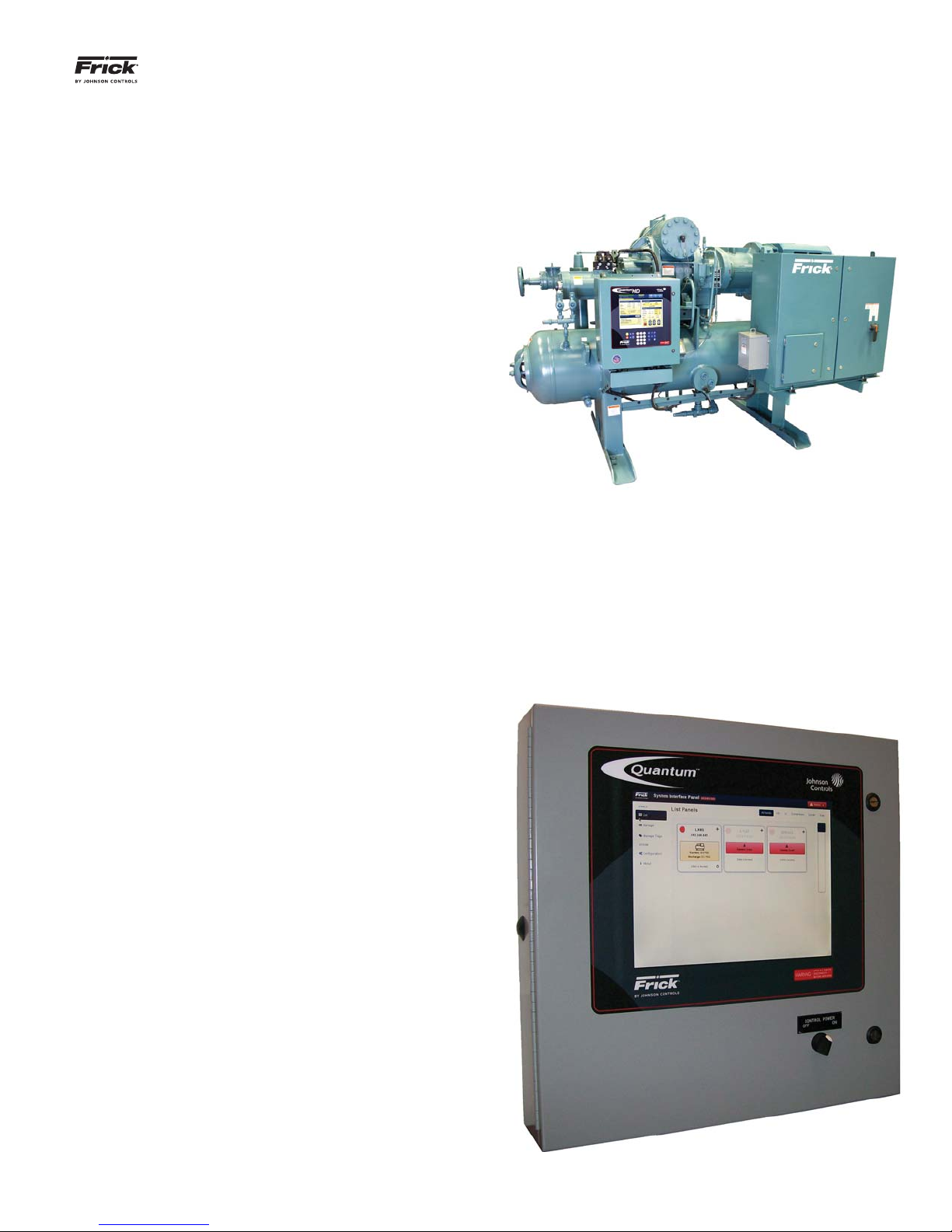
Typical Compressor Package
The following information is presented to help the user to connect and interact with the SIP.
INTRODUCTION TO THE SYSTEM INTERFACE PANEL
General Description
The primary function of the System Interface Panel (SIP)
is to allow a common access point for networking multiple
Frick Quantum™ LX and/or HD panels together, for the
purpose of monitoring and control.
This System Interface Panel (SIP) has been designed to
allow an operator to effi ciently access, control and moni-
tor the operation of all confi gured Quantum™ LX and HD
packages from a single access point, when all units are
connected through a common Ethernet network. The
touch screen control panel is used for intuitive navigation.
The screen display and function is based on web browser
technology, and will closely resemble the look of typical
internet web browser. NOTE: If using a web browser, it
is advisable to use Google Chrome, rather than Internet
Explorer.
The supplied hardware platform consists of a 15 inch (measured diagonally) color resistive touchscreen, and the Q5
microprocessor packaged in a Nema-4 steel enclosure. It is
recommended that a properly confi gured multi-port Ethernet
switch be utilized for the purpose of connecting all desired LX
and HD panels.
System Interface Panel (SIP)
090.030-IOM (OCT 13)
Quantum™ LX
Page 4
QUANTUM™ LX/HD SYSTEM INTERFACE PANEL
INSTALLATION-OPERATION-MAINTENANCE
BASIC SIP CONNECTIONS
The Frick SIP may be connected directly to a single Quan-
tum™ LX or HD panel for a minimum system confi guration, or
it may be connected to an existing Ethernet network.
Connecting the SIP to an existing Quantum™ LX or HD control panel is accomplished by routing a recommended CAT-5
Ethernet cable to each of the panels that you wish to include
in your network (the recommended cables and parts may be
found in any of the Quantum™ LX or HD communications
manuals).
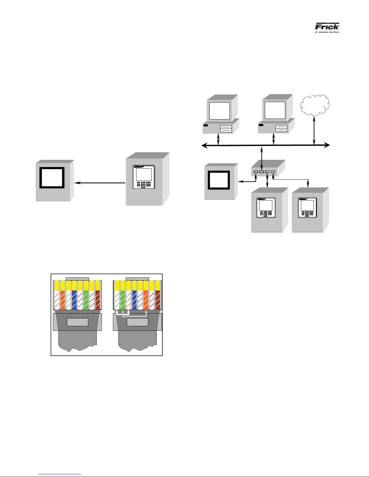
For a Single Panel (Minimum Confi guration) – Only one
CAT-5 cable will need to be run from the panel, and it may
plug directly into the SIP.
Crossover Cable
SIP
Note: Most pre-made, store-bought Ethernet cables
are the straight pin-to-pin variety, and work in most
confi gurations. However, if you want to connect two
Ethernet devices directly together, in this case one
SIP to one Quantum™ LX or HD panel, you will need
to use a crossover Cat-5 cable. Refer to the following
pictorial to construct a crossover cable:
Quantum™ LX or HD
For multiple Panels - Each cable should be routed back
from the Quantum™ LX or HD panel to a common area,
where the ends can be plugged into a switch. The switch
will then have a single cable that connects to the SIP (and
to an optional existing Ethernet network).
Ethernet Network
Switch
Internet
SIP
Quantum™ LX Quantum™ LX
Quantum™ LX or HD Quantum™ LX or HD
1 2 3 4 5 6 7 8
Left (Not Crossed)
3 6 1 4 5 2 7 8
Right (Crossed)
Both Ends of a crossover-cable
CAT-5 Ethernet cable color codes
1 – White w/orange stripe 5 – White w/blue stripe
2 – Orange w/white stripe 6 – Green w/white stripe
3 – White w/green stripe 7 – White w/brown stripe
4 – Blue w/white stripe 8 – Brown w/white stripe
QUANTUM™ LX/HD SYSTEM INTERFACE PANEL
INSTALLATION-OPERATION-MAINTENANCE
LOCATING THE ETHERNET CONNECTIONS
090.030-IOM (OCT 13)
Page 5
NOTE: All Quantum™ HD panels utilize the Q5 processor
board, however, the Quantum™ LX panel may have either a Q4
or Q5 controller. Refer to the photos in this section to identify
which control board is in each of the panels that you propose
to confi gure for SIP usage.
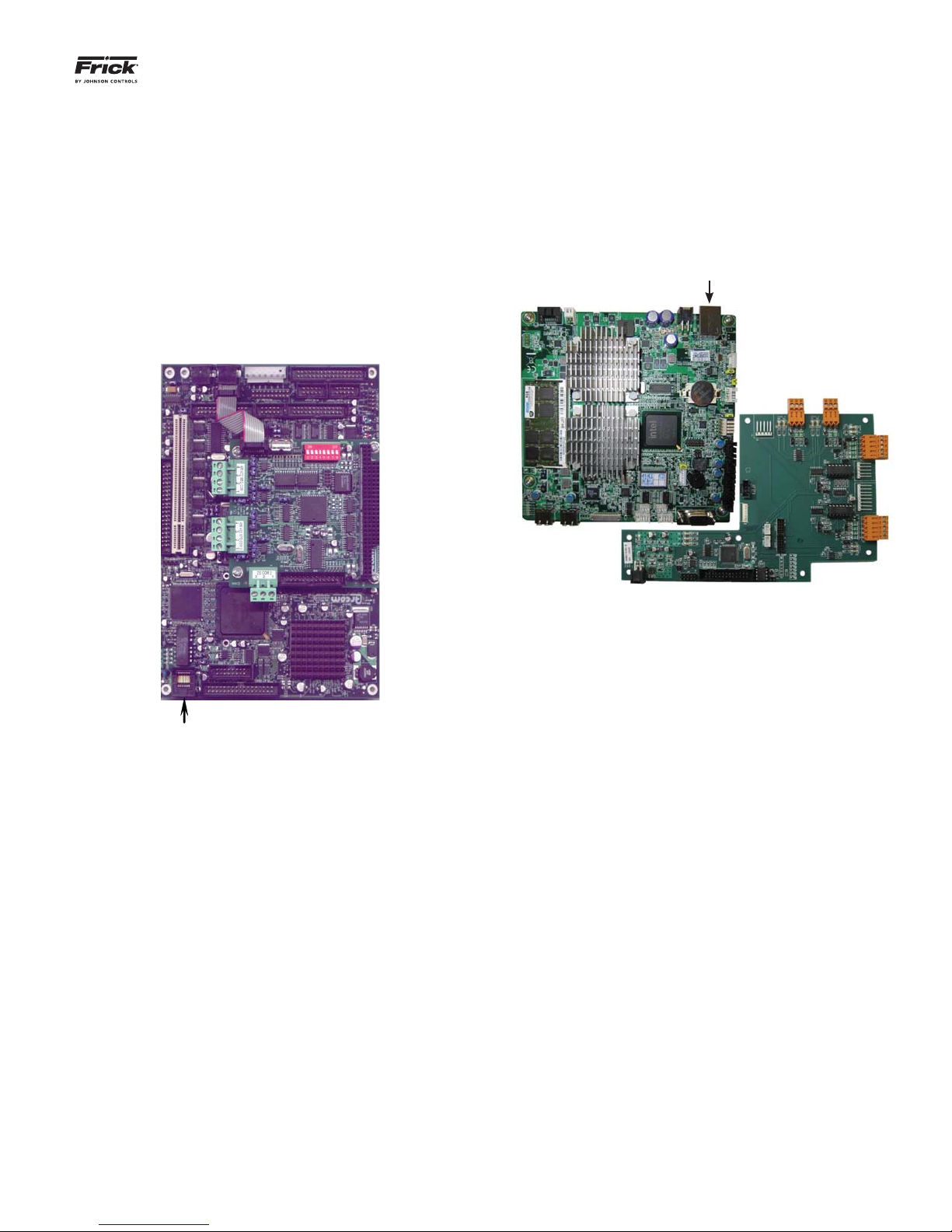
For a Quantum™ LX with a Q4 processor:
The Ethernet connector for the LX Q4 panel can be found
by opening the control panel door, and locating the Q4
controller, as shown here:
For a Quantum™ LX or HD with a Q5 processor:
The Ethernet connector for the Q5 panel can be found by
opening the control panel door, and locating the Q5 controller, as shown here:
Ethernet Connector
Q5 Processer
Ethernet
Connector
Q4 Processor
Plug one end of the cable into the port as labeled. Route
the cable out of the box, and to the point at which it will
either tie into a switch (for multiple connections), or directly to the SIP in the event of a single panel network.
On the SIP Side
Open the panel door of the SIP, and look at the inside of
the door. The location of the Ethernet connection within
the SIP is the same location as shown above for the Q5
processor.

090.030-IOM (OCT 13)
Page 6
QUANTUM™ LX/HD SYSTEM INTERFACE PANEL
INSTALLATION-OPERATION-MAINTENANCE
CALIBRATING THE SIP
Touch Screen Calibration
As the SIP comes from the factory, calibration has already
been performed, and as such, should not be needed. However, it is possible that from time to time, re-calibration
may be warranted. If the cursor does not move to your
fi nger when you touch the screen, then the touch screen
should be re-calibrated.
There are two methods by which the screen may be calibrated. One is to perform a power cycle, the other is to
access the screen calibration button (this second method
will be described in the Confi guration Page section, de-
scribed later).
To perform a power cycle:
1. Turn the Control Power switch to off.
2. Wait several seconds, then turn the Control
Power switch back on.
3. The display will show a series of boot screens,
then the HD logo will appear. Following the HD
logo screen, a prompt will appear for 5 seconds,
allowing access to the Screen Calibration feature:
4. Pressing anywhere on the screen within the fi ve
second countdown will cause the screen to show
the following image in the upper left corner:
5. Notice that the symbol collapses and expands.
Try to touch the red dot within the circle as
closely as possible. When the screen senses your
touch, the symbol will move to its next calibration point. Continue to touch the red dot at each
new location.
6. After the last calibration point has been touched,
the screen is now calibrated, and will either return to the Confi guration screen (if this is where
the calibration was initiated from, or it will fi nish
the boot process if calibration was initiated during power cycle.
NOTE: If, for any reason, after completing the calibration,
the cursor still does not appear where it should be, the
calibration will need to be repeated.
Proper calibration is very important to effi cient screen opera-
tion, especially when utilizing the on-screen keyboard. If the
touch screen is out of a calibration, it can mean that the area
being touched is actually being applied somewhere else, which
can translate into the wrong button keyboard button being
sensed, or the wrong setpoint area detected.

QUANTUM™ LX/HD SYSTEM INTERFACE PANEL
INSTALLATION-OPERATION-MAINTENANCE
SIP PAGE INTRODUCTION
General Information
All available pages will have two areas that are identical.
Using the List page as an example:
Header
Page List
090.030-IOM (OCT 13)
Page 7
Header - The area at the top of all pages shows the Frick
logo, the name “System Interface Panel”, the IP Address,
and fi nally an Alarm notifi cation (described later).
Page List - The area at the left side of all pages provides
a menu to navigate between pages:
• List - Selecting this from any screen will return you
to the List screen.
• Manage - Selecting this will allow you to confi gure all
of the devices that will be controlled and monitored
through the SIP.
• Manage Tags - Selecting this will allow custom naming of panel groups.
• Confi guration - Use this page to confi gure the Ether-
net settings for the SIP.
• About - An informational screen that provides information about the software that this SIP is running.
Some pages will have a slider bar as shown at the right side
of the above screen. Moving the slider up or down will allow
more of the screen content (if present) to be viewed.
090.030-IOM (OCT 13)
Page 8
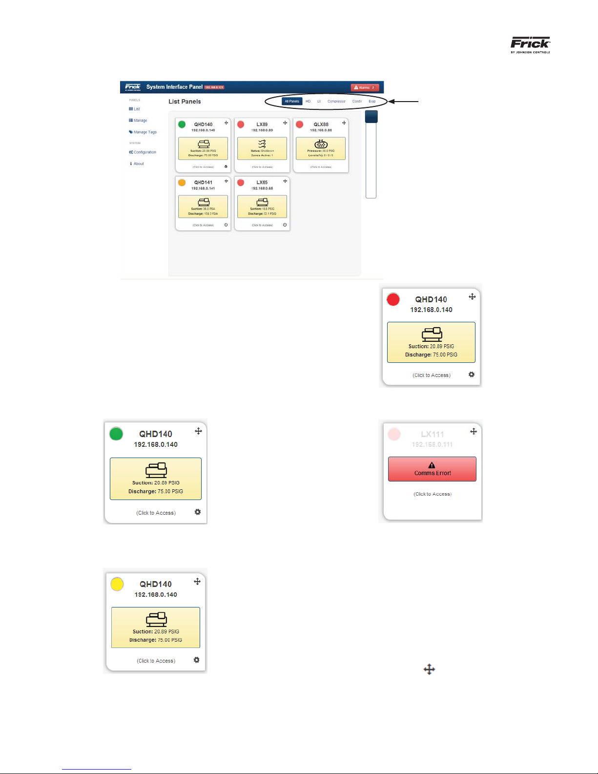
The List page can be thought of as a Home page. It is from
here that an overall picture of the entire system can be viewed.
The List Page displays all the units recognized and accessible
through the System Interface Panel by accessing the Work
Group Tag Names. Any confi gured units will appear with an
icon and a descriptive label. If an icon is touched, the web
browser will be directed to display the Quantum™ LX/HD control page that the icon has been programmed for (described
later).
QUANTUM™ LX/HD SYSTEM INTERFACE PANEL
INSTALLATION-OPERATION-MAINTENANCE
LIST Page
Work Group
Tag Names
The following pictorial shows an example of a confi gured de-
vice:
The green dot in the upper left corner of this icon indicates
that the unit is operating normally and has no active alarms.
A red dot will appear in the upper left corner if the unit is in
shutdown.
A red banner will appear if there is a communications issue
with the unit as well as the words “Comms Error” on the red
bar, indicating a problem with the confi gured device such as:
• The unit may be turned off or not powered
• The unit is not properly confi gured (incorrect IP ad-
dress, etc.)
• Ethernet cable problem.
Notice that each confi gured device icon shown has a 4-way
arrow in the upper right corner:
The yellow dot in the upper left corner of this icon indicates
that the unit has an active alarm/warning.
By touching the arrow in the icon, the device box may be
moved so that the list of all icons may be re-arranged.
If the SIP has not yet been confi gured, then this screen will
have nothing listed for units.
QUANTUM™ LX/HD SYSTEM INTERFACE PANEL
g
g
INSTALLATION-OPERATION-MAINTENANCE
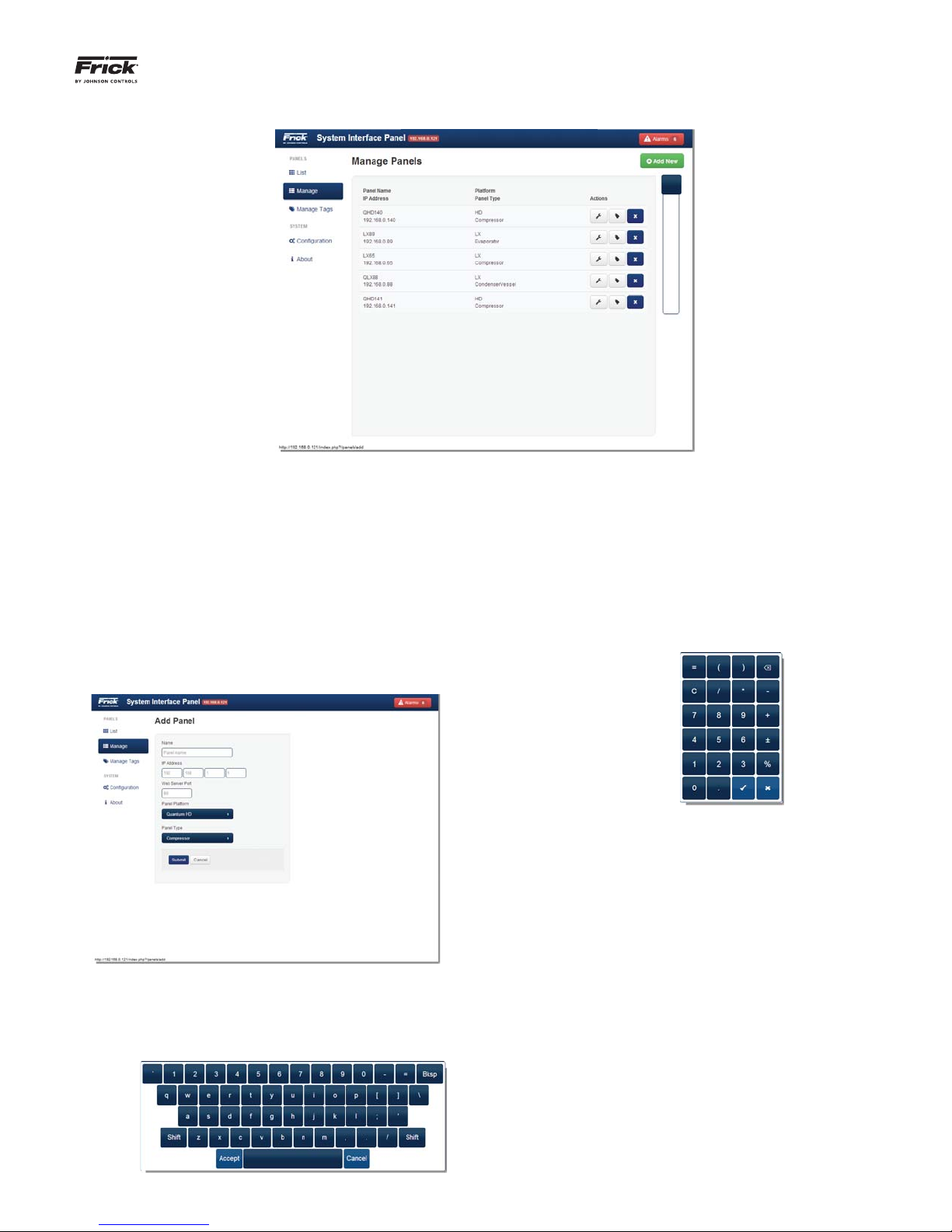
MANAGE PANELS Page
090.030-IOM (OCT 13)
Page 9
This page provides a detailed listing of all panels that have
been confi gured for this system. Panels that are confi gured
here, will be displayed on the List page. A new panel coming
from the factory or one that requires a new program will have
this screen unpopulated, and it will need to be confi gured. Any
time that a new panel is added to the system, or if an existing
panel has to be updated, this page will be used to make those
changes/additions.
To ADD a new panel to this list:
Select the green [Add New] button. The following
screen will appear:
Use this keyboard to enter a unique name that helps
to describe the location or function that applies to the
panel being added. The Name is tied with the IP address. As each IP address is unique, the Panel Name
must be unique also. It is much simpler to identify a
panel by a name rather than a number. Select [Ac-
cept] once satisfi ed with the entry.
IP Address – By selecting the left hand box below the
IP Address designation, a graphic keypad will appear:
Using the keypad, enter the IP address of the device
into the four provided boxes.
Web Server Port - This is traditionally set to 80
which all web browsers understand to be the default
port. It is advisable to consult with the network administrator about this value.
The selections on this screen are:
Name - By selecting inside the box below the Name
designation, a graphic keyboard will appear:
Panel Platform - Select the type of operating platform for the panel, using the following selections:
• Quantum™ LX
• Quantum™ HD
Panel Type - Enter the type of panel (product) using
one of the following choices:
• Condenser/Vessel
• Compressor
• AcuAir
• Evaporator

090.030-IOM (OCT 13)
Page 10
QUANTUM™ LX/HD SYSTEM INTERFACE PANEL
INSTALLATION-OPERATION-MAINTENANCE
Once the above entries have been made, select the [Submit]
button to update the Manage Panels page. The [Cancel] button
will void all changes and return you to the Add Pages screen.
Once a panel or panels have been added, they will now appear
on the Manage Panels page.
Actions -
Selecting this ICON will cause the
Modify Panel page to appear.
Selecting this ICON will cause the
Modify Tag page to appear.
Selecting this ICON will delete
the entire row.

QUANTUM™ LX/HD SYSTEM INTERFACE PANEL
g
INSTALLATION-OPERATION-MAINTENANCE
MANAGE TAGS Page
090.030-IOM (OCT 13)
Page 11
DESCRIPTION: A Tag is simply a name that you may assign for
a Work Group. Each Work group can contain one or multiple
panels. Work Groups do not need to be created, but in facilities where multiple panels exist it can be a benefi t. Use the
Manage Tags page to change the names of Work Groups as
they appear on the List page. Work Group tag names are customizable names that can be created to allow for grouping of
similar product panels. Tags can be created to represent common locations, such as a freezer, dock, warehouse, etc., or by
package type such as Evaporator, Compressor, etc.:
Work Group Tag Names
Confi gured
panels
within a
Work Group
List Panel Page
Actions -
Selecting this ICON will cause the
Edit Tag page to appear (see below).
Selecting this ICON will delete
the entire row.
Edit Tag Page

090.030-IOM (OCT 13)
g
Page 12
This page provides information about the panel.
QUANTUM™ LX/HD SYSTEM INTERFACE PANEL
INSTALLATION-OPERATION-MAINTENANCE
ABOUT Page
These pieces of information will be necessary if factory assistance is ever required.

QUANTUM™ LX/HD SYSTEM INTERFACE PANEL
g
INSTALLATION-OPERATION-MAINTENANCE
CONFIGURATION Page
090.030-IOM (OCT 13)
Page 13
NOTE 1: The proper setup of this screen is critical, and is
best left to the network administrator to perform.
This page is used to provide all of the necessary information so that an existing network will properly recognize
the SIP as a valid device when connected to an existing
Ethernet network. It is basically the same type of procedure you would use when connecting a new desktop or
laptop computer to a network. Once a network recognizes
the SIP, the SIP can be accessed by any computer on the
network, thereby giving the capability to view, monitor,
and change parameters from anywhere on the network.
NOTE 2: It is critical that proper safeguards be in place to
limit this access through passwords and any other security
measures deemed necessary.
The screen consists of the following setpoint boxes:
IP Address – (Internet Protocol) Four setpoint boxes
are provided here. Every machine on an Internet or
Ethernet network must be assigned a unique identifying number, called an IP Address. The IP address
is how the network identifi es each device that is at-
tached. A typical IP address would look like this:
• 216.27.61.137
Gateway Address – Four setpoint boxes are provided
here. The network administrator will provide this address if it is required.
Subnet Mask - Like IP addresses, a subnet mask
contains four bytes (32 bits) and is often written using the same “dotted-decimal” notation. Subnet
masks accompany an IP address and the two values
work together. Applying the subnet mask to an IP address splits the address into two parts, an extended
network address and a host address. For a subnet
mask to be valid, its leftmost bits must be set to ‘1’.
Conversely, the rightmost bits in a valid subnet mask
must be set to ‘0’, not ‘1’. All valid subnet masks contain two parts: the left side with all mask bits set to
‘1’ (the extended network portion) and the right side
with all bits set to ‘0’ (the host portion).
NOTE 3: In the event the web server port or IP address settings are changed, the panel may need to
perform a reboot before these changes take effect.
This it will do automatically, and the user will be notifi ed when this is about to occur.
There are three button selections at the right side of this
screen when viewed locally at the panel. If viewing the SIP
remotely through a web browser, only the Calibration button
will appear:
Calibration - Selecting this button will cause the screen
to be replaced with the Calibrate Touch Screen page, as
described on the CALIBRATING THE SIP page. Simply fol-
low steps 4, 5 and 6 on the CALIBRATING THE SIP page to
perform a screen calibration.
Upgrade Software - This feature is reserved for future
use.
Remove Setpoints - If this button has been selected, you
will be prompted with a warning message asking if you
would like to continue. If you answer YES to the prompt,
ALL setpoint values will be reset to factory default.

090.030-IOM (OCT 13)
g
Page 14
QUANTUM™ LX/HD SYSTEM INTERFACE PANEL
INSTALLATION-OPERATION-MAINTENANCE
ALARM page
The Alarm Page can be accessed from any page by simply
selecting the red button in the upper right corner. If no alarms
are present within the system, that Alarms button will show
zero, otherwise, the number of active alarms will be shown
within the button.
All confi gured panels will be listed on this page, each panel will
be shown on it’s own row. Notice that there is a PLUS symbol
at the beginning of each row. Selecting this PLUS symbol will
show the actual alarm message that is active for that panel
(if any alarms are present). The third column will show a blue
button with a number in it, representing the number of alarms
for that panel. Selecting the Alarm button for any panel, will
allow you to remotely view that particular panel.
QUANTUM™ LX/HD SYSTEM INTERFACE PANEL
INSTALLATION-OPERATION-MAINTENANCE
SIP MAINTENANCE
Q5 CONTROLLER BOARD
090.030-IOM (OCT 13)
Page 15
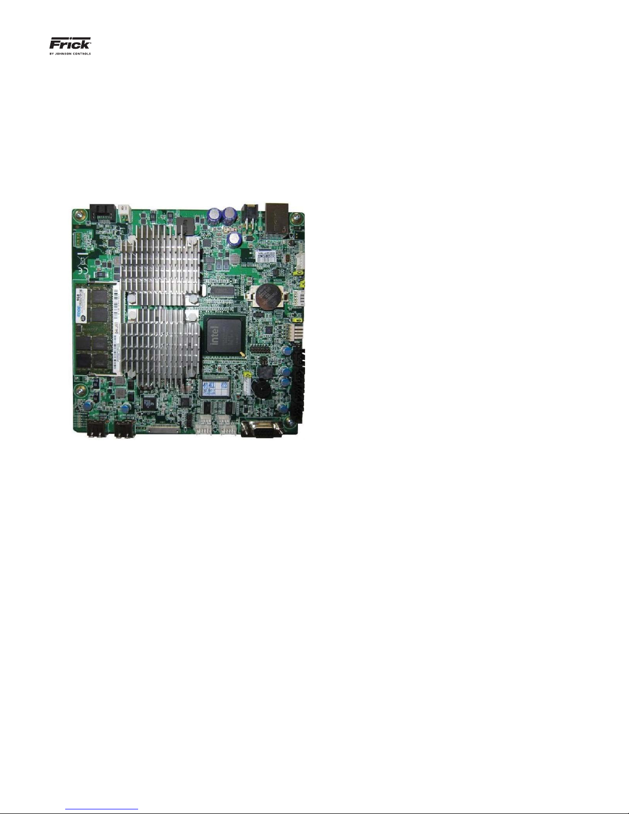
INTRODUCTION
Frick® Controls has released the latest version of the
Quantum ™ Control System. The micro-processor is the
brains of the system and is referred to as the Q5. A photo
of this board appears here:
WHAT IF THE SIP LIST PAGE IS NOT SHOWN
If the List page is not shown, check the following items:
1. If no LED’s are lit on the Q5 board, then check AC
and DC power. Refer to the Power Supply section.
2. Check if the lighting of the LED’s is occurring as
described in the What Should Occur When Applying Powering section.
• If the powering up sequence continues to
repeat without displaying the List page, then
there is a booting problem.
3. Check all plugged connectors for proper seating.
4. Check if an error message is displayed when
booting.
• Be sure to write down any error messages
exactly as they appear, as well as the top
line on the screen where the message appears.
5. Check that the software is OK:
• Is the correct software installed?
FEATURES
The Q5 board includes the following features:
• 6 total USB ports (4 are dedicated, 2 are available)
• 10/100/1000 Mbps Ethernet Connection
• External Video monitor connection
• LED indicators to verify proper operation of various
on board areas (power, Ethernet connectivity, etc.)
• 2 GB RAM memory
• Battery to maintain date and time
WHAT SHOULD OCCUR WHEN APPLYING POWER
When powering up, the following sequence of events are
indicative of a properly working main processor board:
• The six LED’s in the lower left corner should turn
on solid.
• The on-board “buzzer” should “beep” once.
• The display should show several DOS (text) style
screens. A penguin image will appear in the upper left corner of the screen as the boot sequence progresses.
• A Windows style screen with the letters HD will
appear.
• The List (Home) page will appear.
• Did you just install new software?
6. Check the display. If the Q5 board is booting but
you have no display, check the following:
• Check the LED backlight sticks. Look very
closely at the display to see if anything is
visible on the screen. If only a portion look
darkened, it may be that one of the backlights has failed. If the entire screen is dark
(and it is not is sleep mode), use a beam type
source of good lighting, such as a fl ashlight,
look for any ghost type image. If it appears
that there is something on the screen but
very dark, the problem may be with either
the backlight harness, the display or the Q5
board. Check to ensure that both ends of
the backlight harness is plugged in securely.
There is a sticker on the display mounting
plate, that will have a part number that describes the type of display.
• Verify that both the display cable and the
backlight cable are fi rmly seated. It may be
necessary to remove the video cable from
the back of the LCD display and re-seat it
to be sure it is connected properly. Note:
This is a small connector. Caution should
be observed so that it is not damaged due
to excessive force.
090.030-IOM (OCT 13)
Page 16
QUANTUM™ LX/HD SYSTEM INTERFACE PANEL
INSTALLATION-OPERATION-MAINTENANCE
BATTERY FUNCTION AND REPLACEMENT
The Q5 board utilizes a battery to maintain correct date
and time for the purpose of stamping warnings and shutdowns with the date and time that they occurred. If the
date and time are not being maintained properly, this may
indicate that the battery is not functioning, and should be
replaced. The battery may be ordered through Baltimore
Parts (P/N 333Q0001786) or may be purchased at most
electronic shops (manufacturers P/N CR-2032).
The battery is fully assessable, but is surrounded by sensitive electronic components, so care should be taken when
changing.
To replace the battery, ensure that the Control Power
switch has been turned OFF.
Locate the Battery socket, as shown on the following
drawing:
Once a static wrist band is properly donned, place your
fi ngernail under the edge of the battery, and gently lift up.
The battery should release itself from the socket easily.
Take a new battery and place it into the holder in the same
orientation as the old battery (the side with the writing
must be facing out). Return the Control Power switch
back to ON.
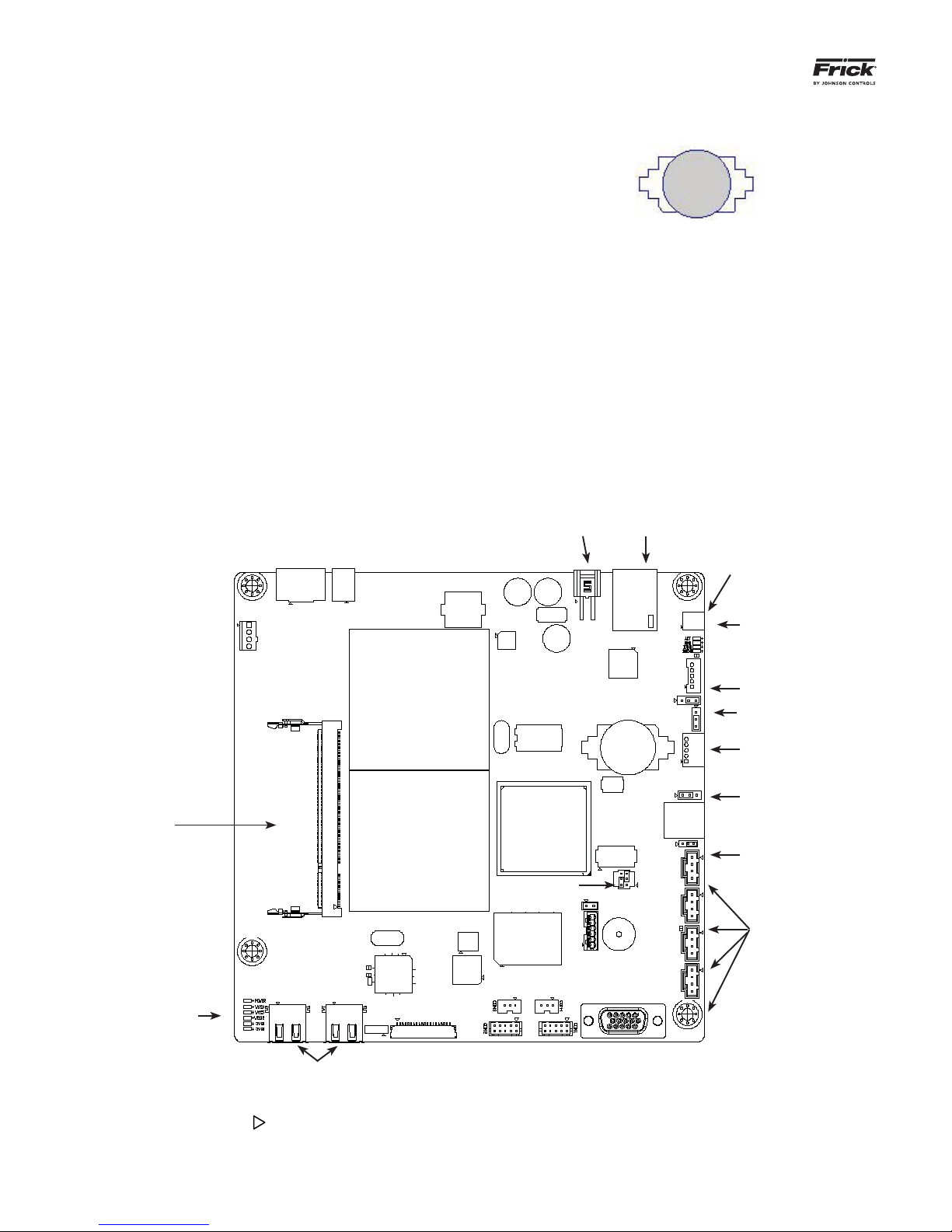
Q5 BOARD PICTORIAL
FUSE
CN_POWER1
Power
Connector
CN1
Ethernet
Connector
Flash Card
located under
the board
here
Ethernet
LED’s
JLVDS3
JLVDS2
BH1
Battery
DIMM1
CN1000
POWER
LED’s
USB
Ports
NOTE 1: The triangle symbol ( ) denotes Pin 1 on connectors. Refer to the chart on the following page for jumper settings.
LVDS1
Display
Connector
CRT1
Video
Monitor
INVERTER1
Inverter
Connector
CMOS1
CN3
USB
Ports
NOTE 2: Do NOT remove the CN4 jumper. Removal of this jumper will cause the processor to not power up.
NOTE 3: Although the Q5 board is the main controller, most of customer connections will be to the Interface board, as shown later.
QUANTUM™ LX/HD SYSTEM INTERFACE PANEL
6
4
2
6
4
2
5
3
1
INSTALLATION-OPERATION-MAINTENANCE
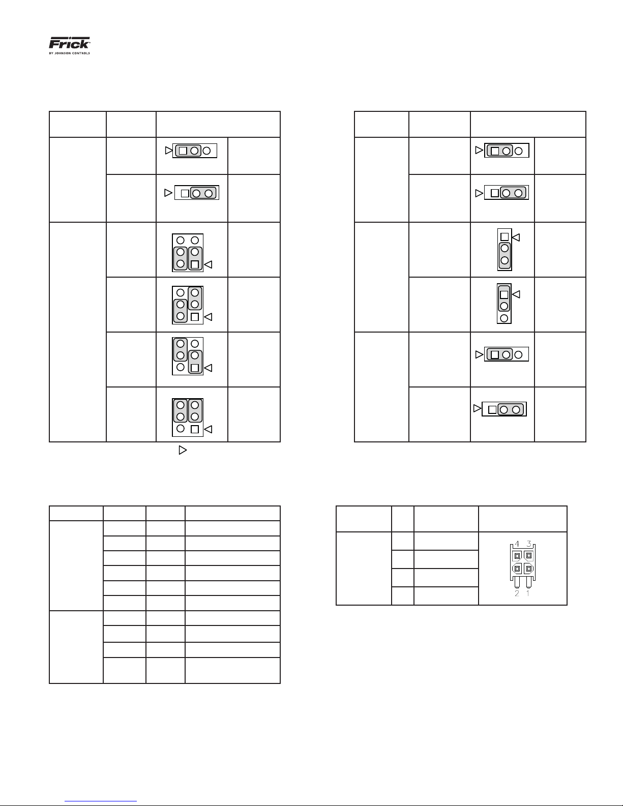
Q5 BOARD JUMPERS, LED’S AND CONNECTORS
JUMPER TABLE
090.030-IOM (OCT 13)
Page 17
Jumper
Title
CMOS1
(CMOS
Clear)
CN1000
(LCD
Resolution
Selector)
Function Jumper Setting
Normal
(default)
Clear
CMOS
24-bit
800x600
24-bit
1024x768
(default)
6
4
2
1 2 3
1 2 3
Closed
Closed
1-3 Closed
5
3
2-4 Closed JLVDS2
1
5
3-5 Closed
3
2-4 Closed
1
18-bit
800x600
18-bit
640x480
6
4
2
1-3 Closed
4-6 Closed JLVDS3
3-5 Closed
5
3
4-6 Closed
1
1 - 2
2 - 3
&
&
&
&
Jumper
Title
CN3
(Touch
Panel Type
Selector)
(Backlight
Level Se-
lector)
(Backlight
Control
Mode)
Function Jumper Setting
5-Wire
Touch
Screen
1 2 3
8-Wire
Touch
Screen
1 2 3
(default)
1
0– 5V
(default)
0 – 2.5V
2
3
1
2
3
Voltage
Mode
1 2 3
PWM Mode
(Pulse Width
Modulation)
1 2 3
(default)
1-2 Closed
2-3 Closed
2-3 Closed
1-2 Closed
1-2 Closed
2-3 Closed
NOTE 1: The triangle symbol ( ) denotes Pin 1 on connectors.
NOTE 2: Jumper CN4 is not shown on this chart, as it must always be installed.
LED DEFINITION TABLE
LED Title Label Color Function
LED1 Red 5VSB
CONNECTOR PINOUT TABLE
Connector
Title
LED2 Red 3VSB
Power
LED’s
LED3 Green VCC 12V
LED4 Green VCC 5V
CN_PWR1
(Power
Input)
LED5 Green VCC 3V
LED6 Blue Power On OK Status
1000MB Green Giga – LAN Speed
CN1000
(LCD
Resolution
Selector)
100MB Yellow 100MB - LAN Speed
10MB Red 10MB –LAN Speed
ACT
Green
(Blinks)
LINK Activity
Pin Function
1 Ground (GND)
2 Ground (GND)
3 VCC 12V
4 VCC 5V
090.030-IOM (OCT 13)
Page 18
QUANTUM™ LX/HD SYSTEM INTERFACE PANEL
INSTALLATION-OPERATION-MAINTENANCE
OPERATOR INTERFACE
DESCRIPTION
The Quantum™ SIP Operator Interface consists of two
components: A color 15” (diagonally measured) graphic
display and a resistive touchscreen and a membrane touch
overlay. The display is used to view information coming
from the Q5 controller, while the touchscreen allows the
operator to navigate the menus.
DISPLAY ASSEMBLY
The Display assembly consists of a 1024 x 768 resolution
LCD screen (which includes LED backlight sticks, and a
wiring harness). Refer to the Parts List at the end of this
manual for specifi c replacement part numbers.
NOTE: Before replacing a display unit, ensure that the
symptom is not actually being caused by a bad backlight LED stick, harness or jumper setting.
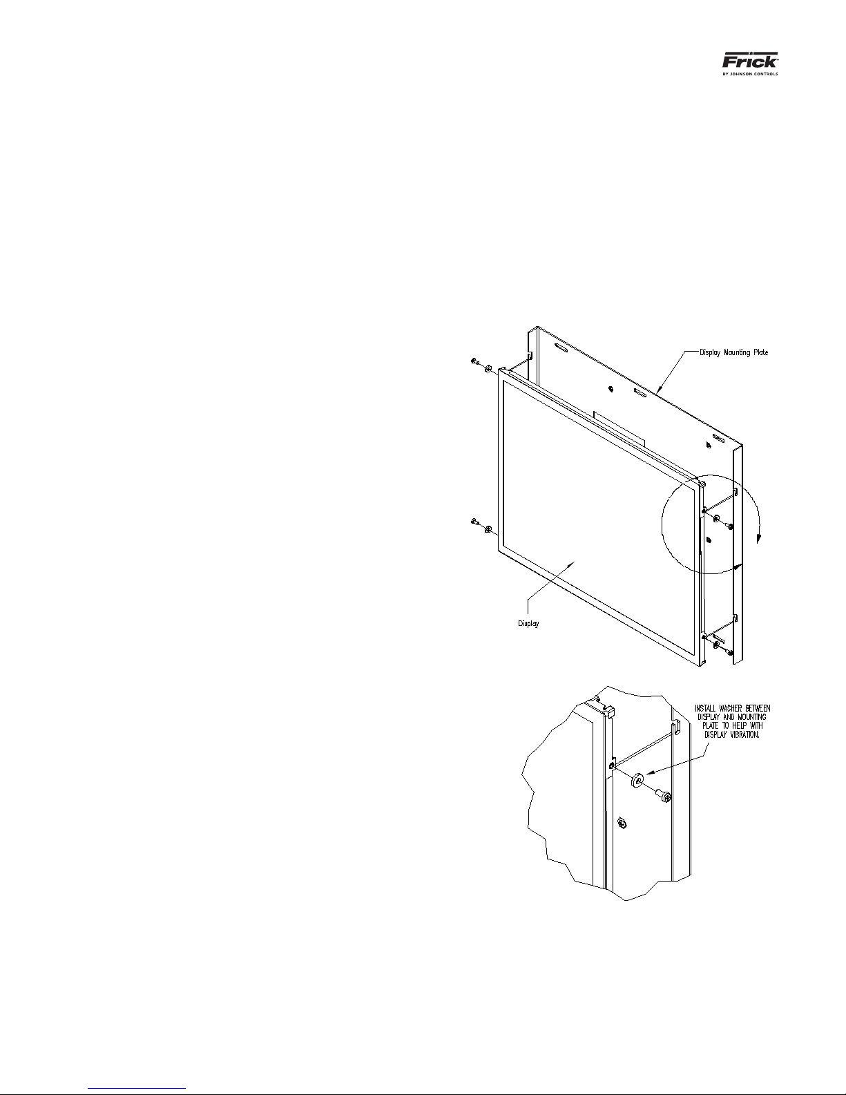
DISPLAY REPLACEMENT
1. Shut off control power.
2. Carefully unplug the touchscreen connector
from the Q5 board. Ensure that you are familiar
with the relocation of this connector.
3. Remove the six nuts that mount the display plate
to the door.
10. Carefully reconnect the display and backlight
connectors on the back of the display.
11. Look at the display from the front of the panel
door. Ensure that the display is centered in the
display opening. Once centered, tighten the six
nuts. Re-centering the display may be necessary
after these steps have been completed.
12. Verify the Q5 Motherboard Display jumper settings per the table shown at on the previous
page.
A
4. Carefully lay the display plate down on a table or
bench, with the display side up.
5. Loosen the four screws located on the display
plate as shown in detail A that follows.
6. Once all four screws have been loosened, carefully slide the display out of the slotted mounting
holes.
7. Remove the four screws and washers located at
the sides of the display.
8. Reinstall the new display by reversing steps 7
and 6, in that order. Use the tool marks left by
the hardware to position the new display.
9. Reinstall the display plate back into position on
the panel door, and loosely reinstall the six hex
nuts, do not tighten yet.
DETAIL A

QUANTUM™ LX/HD SYSTEM INTERFACE PANEL
INSTALLATION-OPERATION-MAINTENANCE
090.030-IOM (OCT 13)
Page 19
TOUCHSCREEN DESCRIPTION
The Quantum™ SIP utilizes an 8-wire resistive touchscreen interface to facilitate operator interaction. It consists of a transparent sheet of glass, which covers the
entire display area, and has numerous rows and columns
of micro wires embedded into its surface. Touching anywhere on the glass will cause an adjacent row and column
of these micro wires to sense the pressure, and signals
the control electronics that a connection has occurred,
and converts the signal to a cursor location. The action is
very similar to the way a computer mouse would be utilized, in that manipulating a mouse moves a cursor around
on the screen, but in the case of a touchscreen, a fi nger
tip causes the cursor to move. The touchscreen allows
the operator to simply touch active areas of the display for
the purpose of changing setpoints, selecting menus, and
accessing other operational features.
If for any reason, the touch screen either doesn’t respond to your touch, or can’t be suffi ciently calibrated
as described previously, a short term solution for screen
navigation can be achieved by using a standard USB style
computer mouse until repairs can be made.
To use a USB compatable computer mouse:
NOTE: Always be aware of the presence of live AC
voltage within the control enclosure!
Open the control panel door, then use the following instructions:
Locate the two USB connections on the Q5
control board, and plug the USB end of the
mouse cable into either one.
The external USB mouse is now active and
ready to use.
If using a mouse, note that by moving it, the onscreen cursor will track it’s movement. Simply
navigate the cursor using the mouse to simulate
a fi nger tip. Click on the screen areas that you
wish to access by pressing the left hand mouse
button. Use the on-screen data and keyboard
entry boxes that appear to enter values and text.
090.030-IOM (OCT 13)
Page 20
QUANTUM™ LX/HD SYSTEM INTERFACE PANEL
INSTALLATION-OPERATION-MAINTENANCE
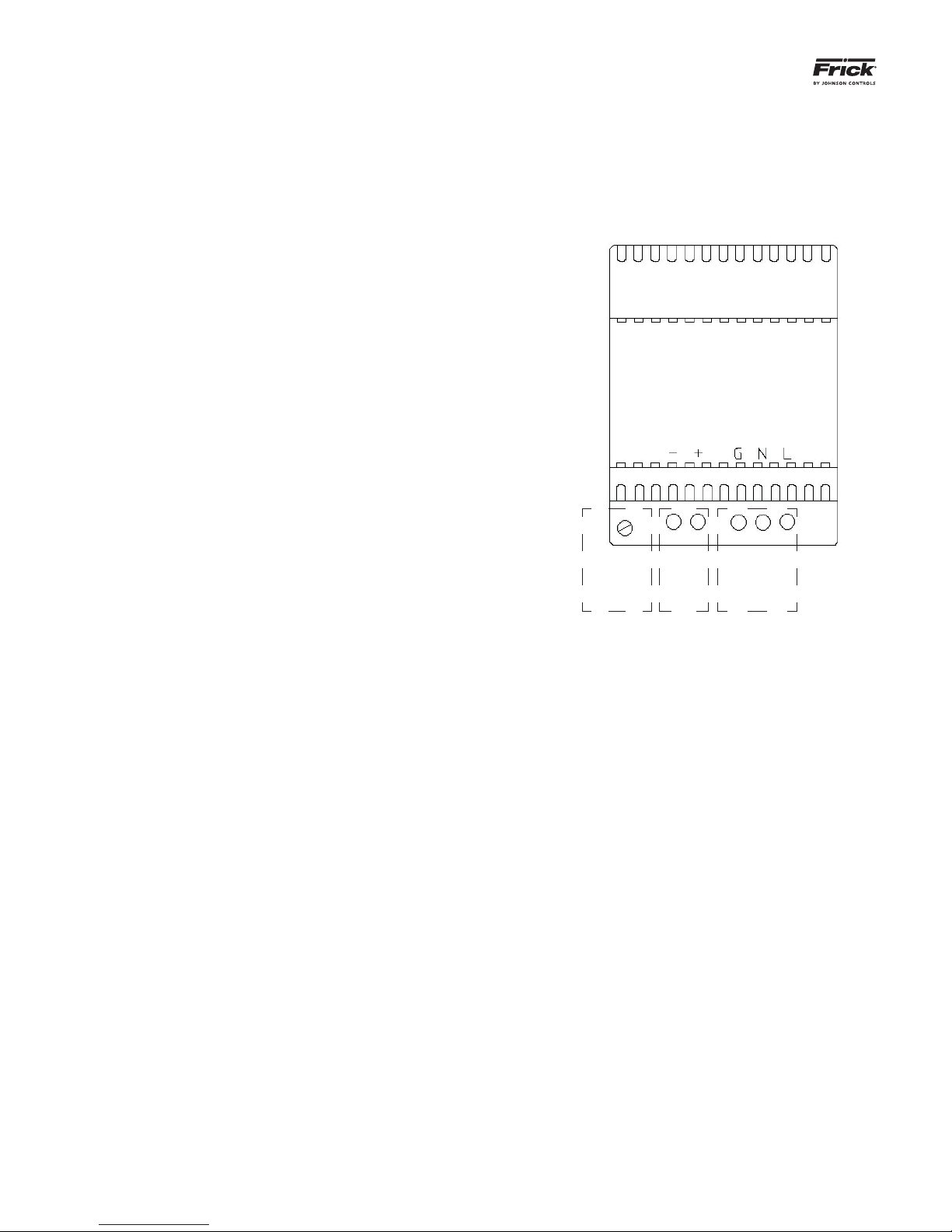
POWER SUPPLY
DESCRIPTION
The power supply of the SIP control panel consists of a
DIN rail mounted 12 VDC power supply, located on the
inside of the front door.
This supply is adjustable and has a green LED indicator to
show that it is powered.
POWER DISTRIBUTION
DC power from the power supply is wired directly to a wiring harness that supplies power to the Q5 control board.
MEASURING VOLTAGE
CAUTION! Measuring and adjusting the power supply
voltage requires the control power switch to be energized. Extreme care must be observed when taking any
readings, as 120 or 230 VAC (depending on incoming system voltage) will be present next to the power supply.
Adjusting the supply requires the use of a small insulated
Philips screwdriver inserted into the supply to access an
adjusting potentiometer. CAUTION: It is possible for the
screwdriver (and the person making the adjustment)
to come into contact with potentially lethal voltages.
Proper Personal Protective Equipment (PPE) measures
need to be observed.
The Q5 control panel requires accurately adjusted DC
voltages to function properly. Periodic measurement and
adjustment of the DC power system is recommended for
optimum system operation. Over time, it is possible for
temperature, humidity, vibration and component age, to
degrade the accuracy of these voltages. If the DC voltage
begins to stray from its optimum range, mysterious problems can begin to arise.
Some examples of problems could be:
• Loss of or intermittent communications failures.
• Q5 reboots for no apparent reason.
• LED's on the Q5 are lit, but nothing appears on
the display.
To perform measurements and adjustment on the power
supply voltage, use a reliable, calibrated Digital Volt Meter
(DVM). The DVM should be accurate to 1/100 of a volt DC.
With the control power switch turned ON, wait until the
List page appears. This is because the graphics required
to create this screen will draw more current than when
the screen is not fully booted. If the screen never appears
however (possibly due to a voltage problem), you will
need to proceed regardless of what is or is not displayed.
In order to properly measure the DC power, it must be
checked at the DC power supply.
V or equivalent), as well as observing proper wire polarity.
The acceptable range for the supply is as follows:
• 12 Volt Supply (+12.10 to +12.20 Vdc)
DCDC
Voltage
Adjust
120 VAC
or
240 VAC
Power Supply
+12 VDC Adjustment
Place the negative lead on the minus (-) terminal
of the supply, and the positive lead on plus (+).
Verify that the DVM is displaying in the range of
+12.10 to +12.20.
If adjustment is required, locate the adjustment access hole on the supply, as previously
shown. While watching the DVM, slowly rotate
the screwdriver blade clockwise to increase the
voltage or counter-clockwise to decrease until
the voltage is correctly adjusted. NOTE: Extreme
care must be used when adjusting the potentiometer. Adjustment should only be performed by qualifi ed personnel. The use of a
non-conductive device is recommended.
POWER SUPPLY REPLACEMENT
If the power supply is found to be bad, or not capable
of acceptable adjustment, the supply will need replacing. Refer to the Recommended Spare Parts list
for the part number.
Ensure that the meter is set to the proper range (DC, 0-50
QUANTUM™ LX/HD SYSTEM INTERFACE PANEL
INSTALLATION-OPERATION-MAINTENANCE
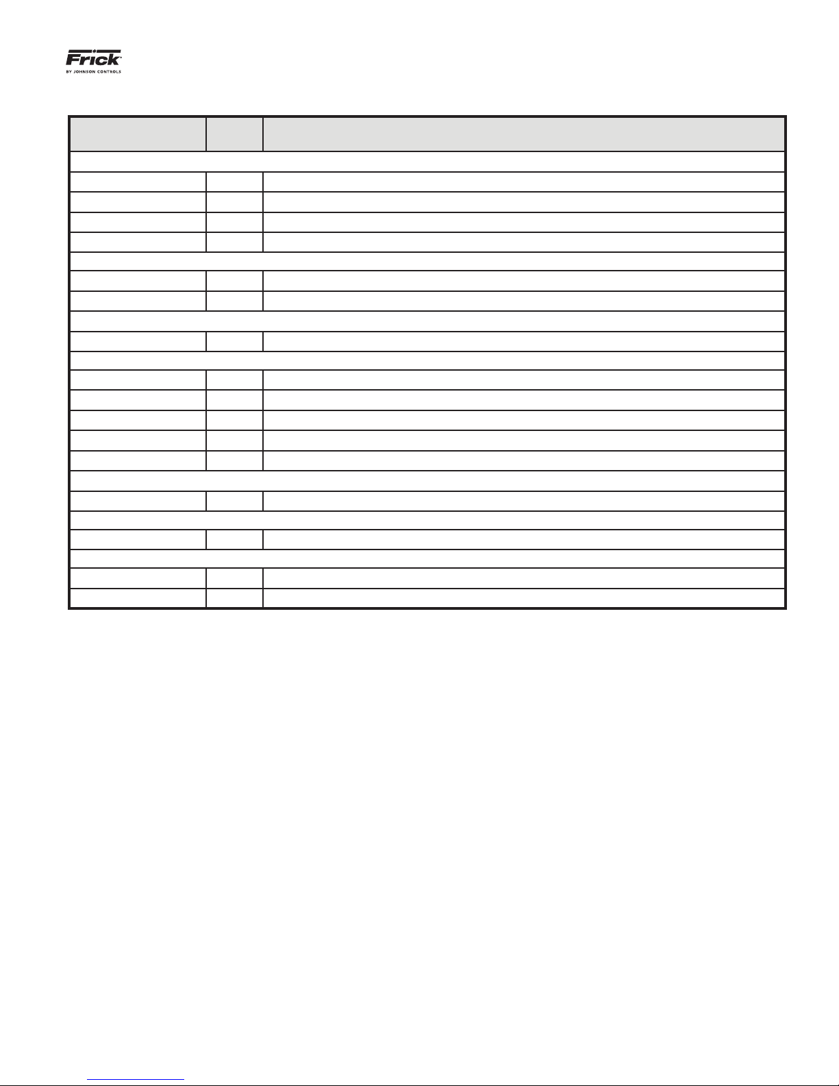
SIP REPLACEMENT PARTS
Frick
Number
639A0185H10 483963 2-Pos. Selector Switch (Control Power)
639A0185H30 483966 Latch, 3 Across (Attaches contact block to switch mechanism)
639A0185H31 483967 Normally Open Contact Block (for Control Power Switch)
639A0206H05 484047 Circuit Breaker, 5 Amp.
639D0199H01 703164 15” Color Display (Indoor)
649D6101G01 1032704 Touchscreen glass w/overlay of Frick logo
639A0290G07 1073320 Quantum™ SIP Program Flash Card (Version 2.00)
639B0116H01 677556 DC power-I/O Comms harness
639D0236H01 105758 SIP Harness, Ground
639B0118H01 670744 Display Harness
639B0126H01 884854 LED Inverter Harness
639D0191H03 696516 Harness Kit, Q5 to Interface Board Interconnect
333Q0001786 N/A Battery, 3V (located on Q5 board)
639B0115H02 642308 DC power supply – 12 VDC
649C1158G01 1034948 Q5 (Advantech Q5) (Does not include interconnect harness kit)
639B0116H01 677556 Interface Board (Does not include interconnect harness kit)
SAP
Number
Description
Control Power
Display Accessories
Flash Cards and Software
Harnesses
Miscellaneous
Power Supply
Q5 Boards
090.030-IOM (OCT 13)
Page 21
090.030-IOM (OCT 13)
Page 22
QUANTUM™ LX/HD SYSTEM INTERFACE PANEL
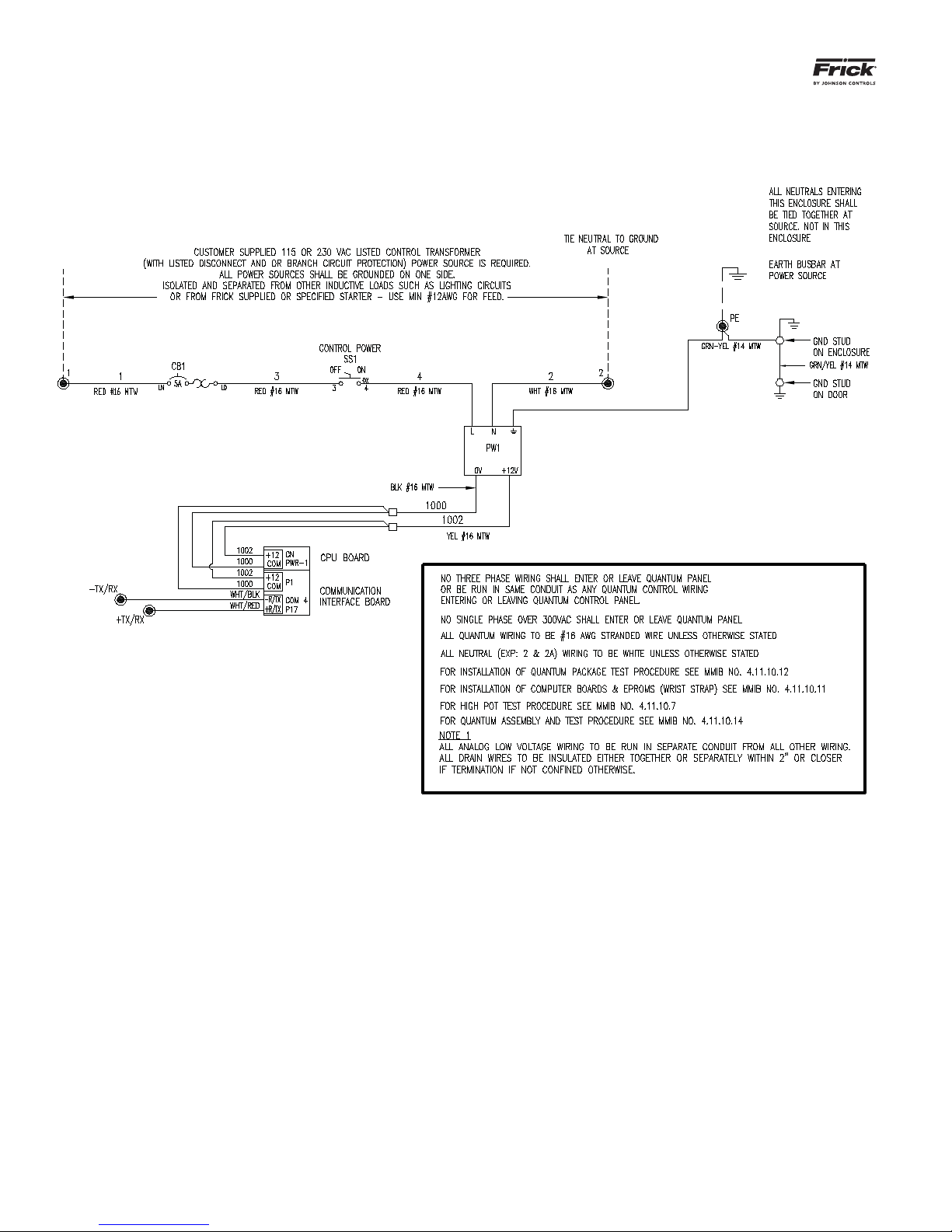
INSTALLATION-OPERATION-MAINTENANCE
Wiring Schematic

QUANTUM™ LX/HD SYSTEM INTERFACE PANEL
INSTALLATION-OPERATION-MAINTENANCE
090.030-IOM (OCT 13)
Page 23

090.030-IOM (OCT 13)
Page 24
QUANTUM™ LX/HD SYSTEM INTERFACE PANEL
INSTALLATION-OPERATION-MAINTENANCE
Form 090.030-IOM (2013-10)
Supersedes: 090.030-O MAR 12
Subject to change without notice
2013 Johnson Controls Inc. - ALL RIGHTS RESERVED
Printed In USA - GUI 1M .20
JOHNSON CONTROLS
100 CV Avenue P.O. Box 997
Waynesboro, PA USA 17268-0997
Phone: 717-762-2121 FAX: 717-762-8624
www.johnsoncontrols.com
 Loading...