

Frick Quantum ACUair Service Manual

S90-500 O/JUL 2002
File: SERVICE MANUAL - SECTION 90
Replaces: S90-500 O/APR-2001
Dist: 3, 3a, 3b, 3c
OPERATION
FRICK® QUANTUM™
®
ACUair
CONTROL PANEL
Version 2.1x

S90-500 O FRICK® QUANTUM™ ACUair® CONTROL PANEL
Page 2 OPERATION
Table of Contents
OVERVIEW OF OPERATOR INTERFACE ...............................................................................................................3
OPERATOR ACCESS......................................................................................................................................... 3
Keys And Key Functions ............................................................................................................................... 4
Keypad Keys........................................................................................................................................... 4
Screen Keys ........................................................................................................................................... 5
To Change Setpoints........................................................................................................................ 5
INITIAL SETUP PROCEDURE............................................................................................................................ 6
GRAPHIC SCREENS.................................................................................................................................................6
“AIR HANDLING UNIT OVERVIEW” SCREEN ................................................................................................... 6
Screen Key Set ............................................................................................................................................. 7
UNIT SELECTED - "OPERATING STATUS" SCREEN ......................................................................................8
Air Handling Unit Data Box............................................................................................................................ 8
Alarm Status Box........................................................................................................................................... 8
Demand Output Box...................................................................................................................................... 8
Analog Readings Box.................................................................................................................................... 9
Operator Selection Keys ............................................................................................................................... 9
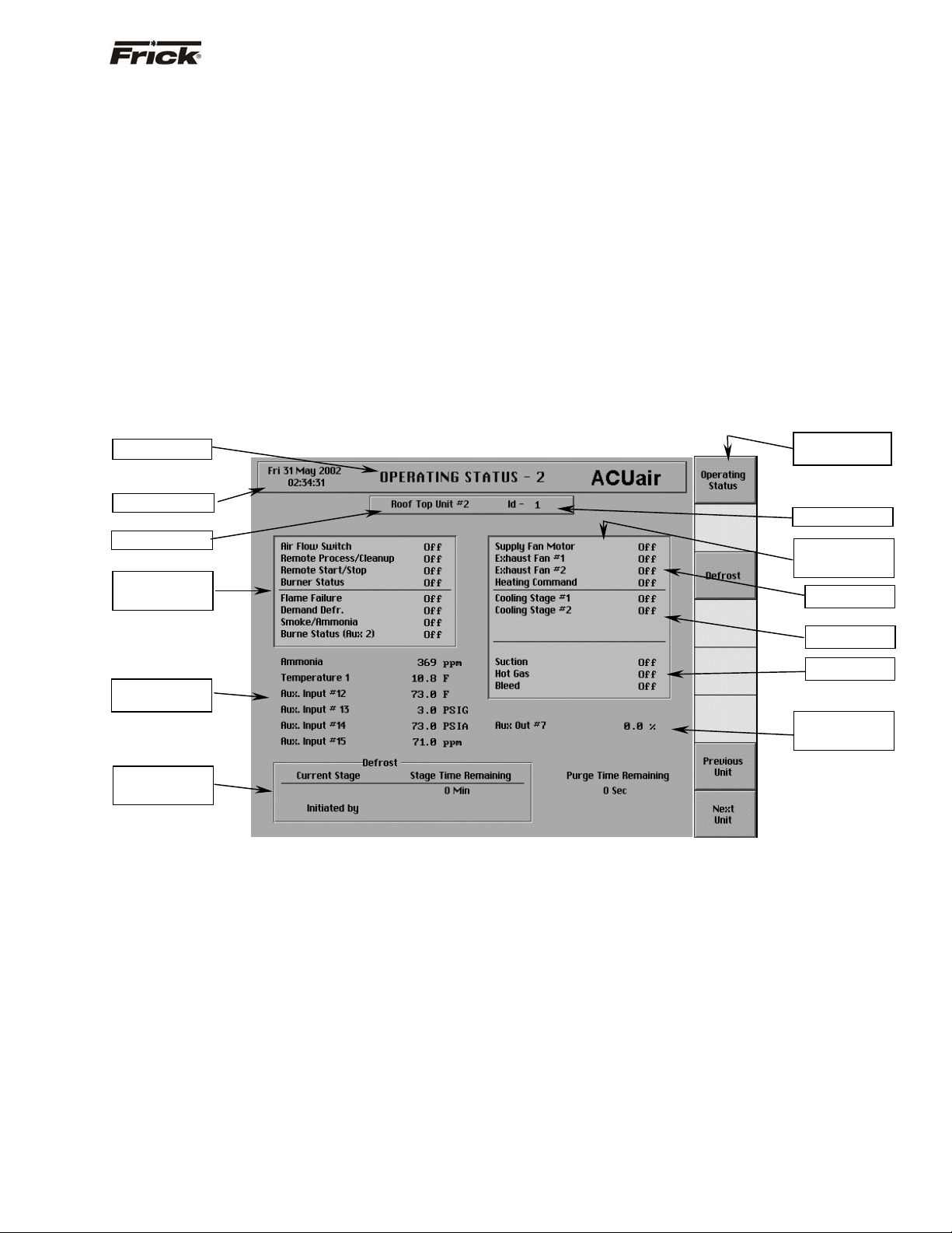
UNIT SELECTED - "OPERATING STATUS - 2" SCREEN ................................................................................. 9
ACUair® Input Status Box............................................................................................................................. 9
ACUair® Output Status Box.......................................................................................................................... 9
Sensor Indication......................................................................................................................................... 11
Defrost Status Box ...................................................................................................................................... 11
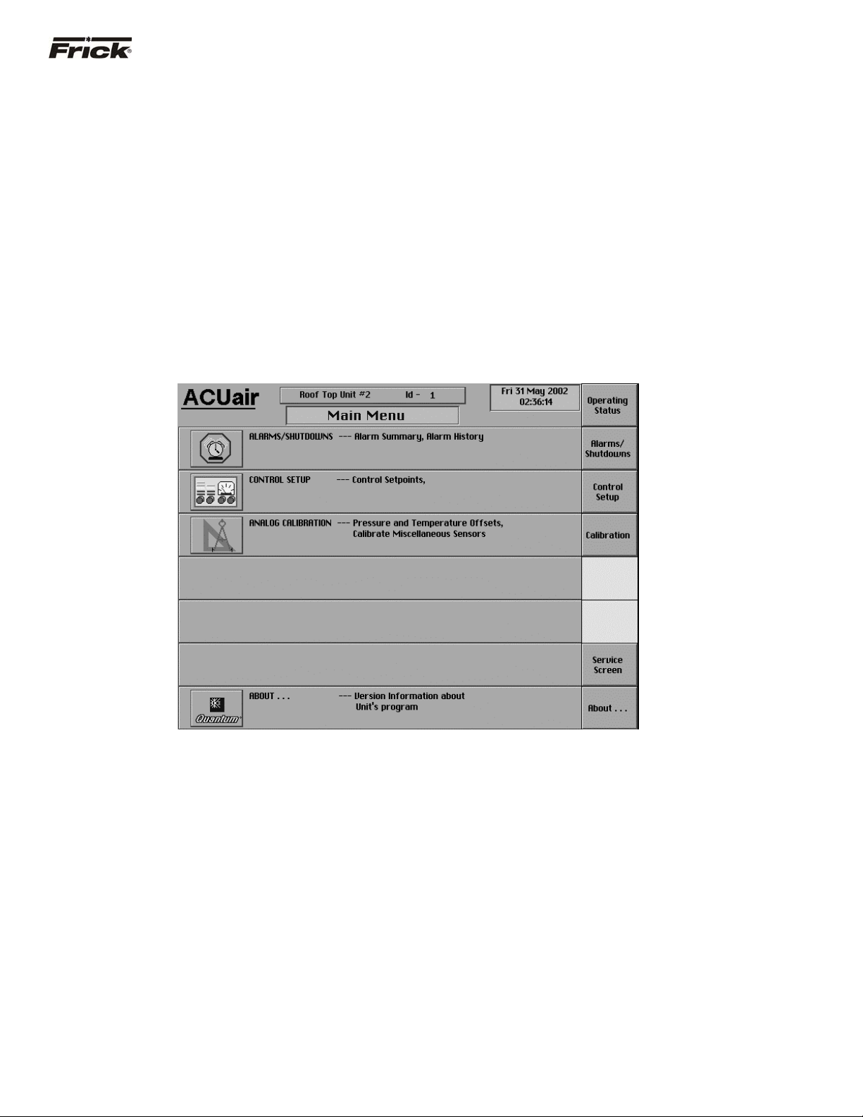
UNIT SELECTED - "MAIN MENU" SCREEN .................................................................................................... 11
Screen Key Set ........................................................................................................................................... 11
MAIN MENU SELECTION
"Alarms/Shutdowns" Screen................................................................................................................................... 11
"Alarms/Shutdowns History" Screen .............................................................................................................. 11
Main Menu Selection - "Control Setup" (1) Screen ............................................................................................. 12
Main Menu Selection - "Control Setup" (2) Screen ............................................................................................. 13
CONTROL SETUP
“Cooling Control Setup” Screen .................................................................................................................. 14
"Heating Control Setup" Screen .................................................................................................................. 15
“Exhaust Control Setup” Screen.................................................................................................................. 16
“Damper Control Setpoint” Screen .............................................................................................................. 17
“Heat Profile Control” Screen................................................................................................................ 18
“Safety Setpoints” Screen ........................................................................................................................... 18
ANALOG CALIBRATION
"Main Menu" Screen.................................................................................................................................... 18
"Analog Calibration" Screen.................................................................................................................. 19
"Pressure Calibration" Screen ..............................................................................................................20
"Temperature Calibration" Screen ........................................................................................................ 21
"Other Calibration" Screen.................................................................................................................... 22
PANEL SETUP
“Panel Setup” Screen .................................................................................................................................. 23
SECURITY SETUP SCREEN............................................................................................................................ 25
PANEL STATUS
"Real Time Trending" Screen...................................................................................................................... 26
"Real Time Trending" Screen – Data Log View .................................................................................... 27
"Real Time Trending" Screen – Trending View ....................................................................................28
"History Trending" Screen ........................................................................................................................... 29
ALARMS/SHUTDOWNS MESSAGES ....................................................................................................................30
INDEX ......................................................................................................................................................................31

FRICK® QUANTUM™ ACUair® CONTROL PANEL S90-500 O
g
OPERATION Page 3
Warnin
!
The Quantum™ has the capability of being modified by the user/owner in order to obtain different performance
characteristics. Any modification to the standard default settings may have a severe negative impact on the
operation and performance of the equipment. Any modification to these control settings is the sole responsibility of
the user/owner and Frick® disclaims any liability for the consequences of these modifications. It is possible that the
modification of these settings may cause improper operation and performance that results in property damage,
personal injury or death. It is the responsibility of the user/owner to evaluate and assess the consequences of their
actions prior to modifying the controls for this unit.
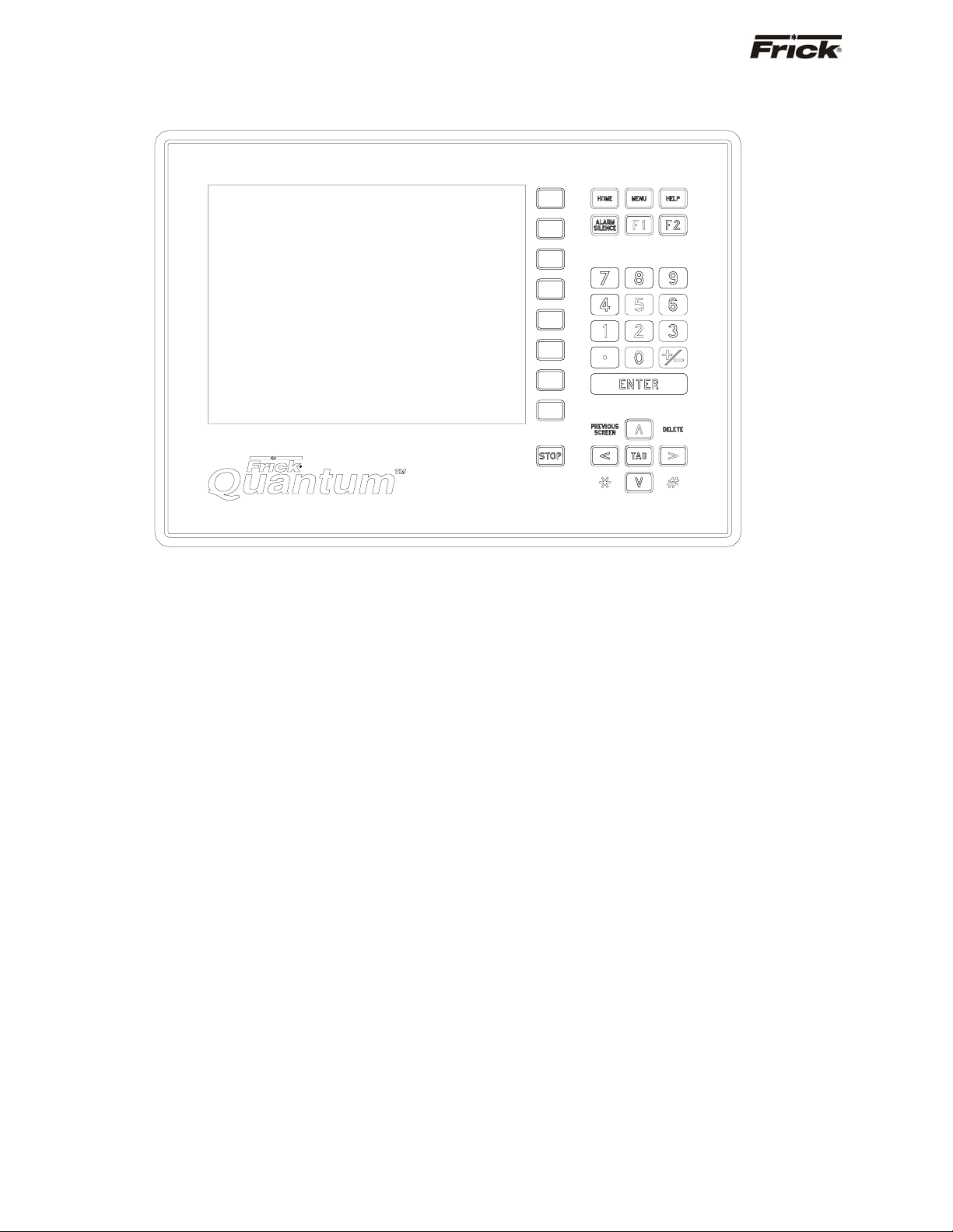
OVERVIEW OF OPERATOR INTERFACE
The panel user interface has been designed to allow an
operator to efficiently access and control the operation of
the units. The control panel screen is used for graphic
displays. By pressing a key on the keypad, the labeled or
described function is recognized by the control processor.
The following information is presented to help the operator
interact with the graphic screens and the Quantum™
ACUair® control panel. This manual is intended to
describe all presently available features.
OPERATOR ACCESS
Operator access to this system is through various
screens. A screen is the physical representation of data
on the display. Icons have been used to help an operator
quickly identify functions. An icon is a small graphic
symbol representation. Each screen has a title area. The
title is descriptive of the screen. The current date and time
is shown in this title area. The day of the week, Sunday
(Sun.) through Saturday (Sat.) is displayed. The month of
the year from January (Jan.) to December (Dec.) is
displayed. The day of the month from 1 to 31 and the year
from 0001 to 9999 is displayed. The time displayed is the
current time in 24 hours (military) format. The hours,
minutes and seconds are displayed. The labeled keys on
the panel keypad provide quick access to the operator's
needs. By pressing a labeled key on the keypad, the
corresponding function is recognized. Most of the screens
have screen keys that describe or show a function that is
recognized when the coinciding key found at the right of
the display screen is pressed. The screen keys provide
access to other screens or commands. For easier
viewing, related information is separated into boxes. The
setup and setpoint entry is separated into logical control
components. Setup selection of features and options has
been provided to prevent the operator from unnecessary
viewing and entering of unused control settings. The
required control settings are clearly presented. To further
assist the operator, an on-line help is provided.
Sometimes selections appear differently to indicate that
the feature is unavailable.
S90-500 O FRICK® QUANTUM™ ACUair® CONTROL PANEL
Page 4 OPERATION
KEYS AND KEY FUNCTIONS
KEYPAD KEYS
Following is a list of the labeled keypad keys and the
actions that occur when they are pressed:
[HOME] – If an operator is logged on to an individual unit
and the “Operating Status” screen is not presently
showing, then this unit’s “Operating Status” screen is
shown when this key is pressed. Otherwise, the “Air
Handling Unit Overview” screen is shown. All the pertinent
readings and operational status of a unit is shown on the
“Operating Status” screen. An overview of the most
important information about all the units is shown on the
“Air Handling Unit Overview” screen.
[MENU] - Shows the "Main Menu" screen. This screen
has the main selections for an individual unit, allowing
access to information, setup of options, and setpoint
entry.
[HELP] - Displays the on-line "HELP". Information is
shown for the operation of the ACUair
[F1] - A function key that is only active when a screen
indicates it as a selection key. Its function is dependent on
what the screen indicates will occur.
[F2] - A function key that is only active when a screen
indicates it as a selection key. Its function is dependent on
what the screen indicates will occur.
NUMERALS [0] - [9] - The numerical keys are used to
enter a value in a data field.
®
control panel.
DECIMAL [.] - The decimal point is used when entering a
decimal value in a data field.
[+/-] - When changing a value in a data field, this key will
toggle the value between negative and positive.
[ENTER] - When changing data in a data entry field, this
key will input the change.
[PREVIOUS SCREEN] - Shows the screen that was
viewed previously to the current screen. Also is used to
return to the previous set of screen keys when accessing
different sets of screen key selections on the same
screen.
[DELETE] - When changing a value in a data field, this
key will delete the selected character.
Up Arrow [Ù]- When in the mode of changing setpoints,
this arrow is used to go to the previous data entry field.
Down Arrow [Ú]- When in the mode of changing setpoints,
this arrow is used to go to the next data entry field.
Right Arrow [>]- When in the mode of changing setpoints,
this arrow is used to go to the next data entry field. When
in the mode of changing a data entry field, this arrow is
used to go to the next character.
Left Arrow [<]- When in the mode of changing setpoints,
this arrow is used to go to the previous data entry field.
When in the mode of changing data entry field, this arrow
is used to go to the previous character.

FRICK® QUANTUM™ ACUair® CONTROL PANEL S90-500 O
g
OPERATION Page 5
SCREEN KEYS
Most of the screens have screen keys that are graphically
depicted. They describe or show a function that is
recognized when the coinciding keypad key to the right of
the screen is pressed. A set of screen command keys
have a title area to describe the command control.
Following are descriptions of the commonly used screen
keys:
[Change Setpoints] - When on a screen that has
adjustable setpoint values, this positions the cursor at
the first data entry field. (See “To Change Setpoints”
for more information.)
[OK] - Available when in the mode of changing
setpoints, this accepts all data changes. Available as
a response to a message, this approves continuing.
[CANCEL] - Available when in the mode of changing
setpoints, this rejects all data changes. Available as a
response to a message, this disapproves continuing.
Arrows - Available when in the changing setpoints
mode, they function the same as the panel keypad
arrows.
[Increase Value] - Available when in the changing
setpoints mode, this increases the selected setpoint
by one unit each time it is pressed.
[Decrease Value] - Available when in the changing
setpoints mode, this decreases the selected setpoint
by one unit each time it is pressed.
[Up One] - Scrolls the data on the screen to show the
previous line of data.
[Down One] - Scrolls the data on the screen to show
the next line of data.
[Page Up] - Scrolls the data on the screen to show
the previous page of data.
[Page Down] - Scrolls the data on the screen to
show the next page of data.
[Goto Start] – Scrolls the data on the screen to show
the most recent data.
[Goto End] - Scrolls the data on the screen to show
the oldest data.
[More…] - Available when the selections are on more
than one screen. Used to go to the next selections.
[…Back] - Available when the selections are on more
than one screen. Used to go back to the previous
selections.
[Enable] - Available to place the indicated control
setpoints or option into usage.
[Disable] - Available to remove the usage of the
indicated control setpoints or option.
TO CHANGE SETPOINTS
Warnin
!
The Quantum™ has the capability of being modified
by the user/owner in order to obtain different
performance characteristics. Any modification to the
standard default settings may have a severe negative
impact on the operation and performance of the
equipment. Any modification to these control settings
is the sole responsibility of the user/owner and Frick
disclaims any liability for the consequences of these
modifications. It is possible that the modification of
these settings will cause improper operation and
performance that results in property damage,
personal injury or death. It is the responsibility of the
user/owner to evaluate and assess the consequences
of their actions prior to modifying the controls for this
unit.
The setpoints define the operation and limits of the air
units. Adjustable setpoints are setpoints that an operator
can easily change in the field. These setpoints are stored
in EPROM (non-volatile memory).
NOTE: Adjustable Setpoints are not lost after power is
interrupted. However, we suggest that a list of Adjustable
Setpoints be recorded and stored safely to facilitate
reentry, in case there is a need to return to the original
settings.
1. From an adjustable setpoint screen, select the
[Change Setpoints] key. This positions the
cursor at the first data entry field. The data entry
field that is selected is identifiable by the black
background and white text.
2. Use the arrow keys to move the cursor to the
data entry field to be modified.
3. Having selected the setpoint to be changed, the
numerical keys and the decimal key may be used
to enter the new setpoint. Typing a new value will
completely erase the old value.
4. To remove a typing mistake, the left and right
arrow key can be used to position the cursor to
the left of the mistake and then press the
[DELETE] key to erase it.
5. Press the [ENTER] key to input the new data in
the data entry field and to move to the next data
entry field.
6. If the value is out of bounds, an error message
box displays the proper range of values. Press
the [OK] key to acknowledge the error message.
Re-enter the correct value.
7. When finished making any changes to the data
on an adjustable setpoint display press the [OK]
key to accept all changes or press the
[CANCEL] key to ignore all changes.
®
S90-500 O FRICK® QUANTUM™ ACUair® CONTROL PANEL
Page 6 OPERATION
INITIAL SETUP PROCEDURE
1. “Panel Setup” is performed first. “Panel Setup” is
used to setup panel features and options that later
can be changed by an operator. Features such as the
panel time, and screen color are changed here.
2. “Unit Board Setup” is performed next. “Unit Board
Setup” is used to setup the customer specific control
features and options to be used by a unit controller
board. This setup should not need to be changed by
operators. “Unit Board Setup” is intended to be
GRAPHIC SCREENS
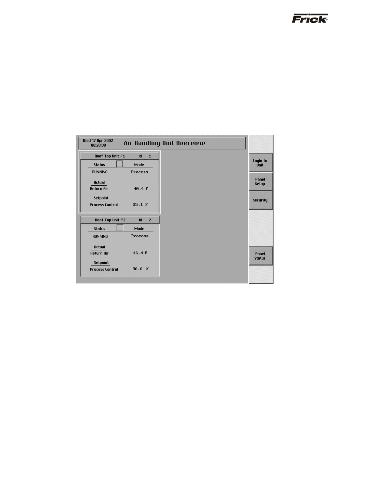
“AIR HANDLING UNIT OVERVIEW” SCREEN
accessed and performed only by a Factory
Representative or Distributor.
3. Calibrate the control devices.
4. From Control Setup enter and setup the control
settings.
5. From Security Setup, establish the desired access
rights of the operators.
The panel now provides quick access to the most
important information and controls of the units and their
subsystems.
Also called the "Home" screen. This screen shows an
overview of the most important information about the
units. This screen is shown when power is first turned on
and when a key is pressed after the screen saver has
turned off the backlight. The "Air Handling Unit Overview"
screen is continuously updated and provides the current
status of each unit's condition and performance.
The following information is shown on this screen:
· ID - The identification number of the unit
displayed.
· Name - The identification name that describes
the unit that is displayed.
· Status – The present operation status of the unit.
· Mode - The present mode of the unit, either
Cleanup or Process.
· Actual - The current reading of the present
analog control value.
· Setpoint - The setpoint that is currently being
maintained.
Several types of failures and alarms are also
indicated on this screen. If a unit stops
communicating with the Quantum™, the information
specific to that unit is shown in red text. After
communications with the unit has been restored, the
text color will return to black. In addition, a list of the
units that have previously been communicating with
the Quantum™ is saved even when powered off. If a
unit in that list does not respond to the Quantum™
during the starting sequence, the words “Not Found”
are displayed in red in place of that unit’s name.
Once a proper connection with the unit is made,
logging in to the unit will replace the words “Not
Found” with the unit’s name. Finally, when a unit is in
an alarm condition, a red circle flashes in the small
box between "Status" and "Mode" until the alarm is
cleared.
FRICK® QUANTUM™ ACUair® CONTROL PANEL S90-500 O
OPERATION Page 7
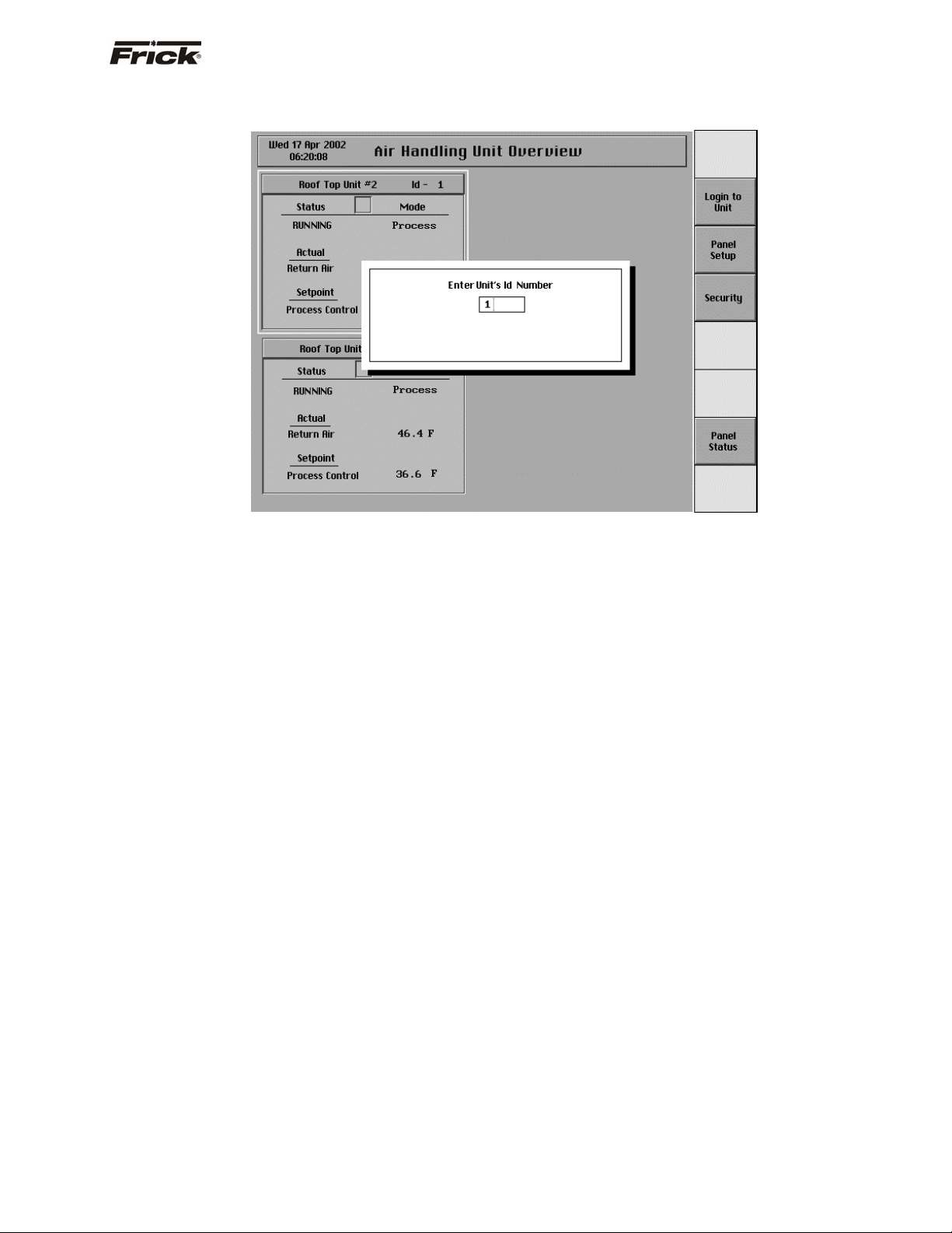
“AIR HANDLING UNIT OVERVIEW” SCREEN –
SCREEN KEY SET
Following are the screen key selections for the "Air
Handling Unit Overview" screen:
· [Login to Unit] - Shows a selection box for the
Unit ID. After a valid ID is entered, the “Operating
Status” screen for that unit is displayed.
· [Panel Setup] - Shows the "Panel Setup"
screen. This screen has the following menu
items for setup:
· Change Current Time and Date
· Temperature Units
· Change Communications
· Selectable Options
· Screen Setup
· [Security] - Shows the current security privilege
level and whether setpoints can be changed from
the keypad. Security can be changed on this
screen.
· [Panel Status] – Shows the Quantum™ control
panel internal temperature, as well as the Panel
Control status (manual or remote). This screen
also shows the last time the Quantum™ panel
was powered up and powered down.
S90-500 O FRICK® QUANTUM™ ACUair® CONTROL PANEL
y
Page 8 OPERATION
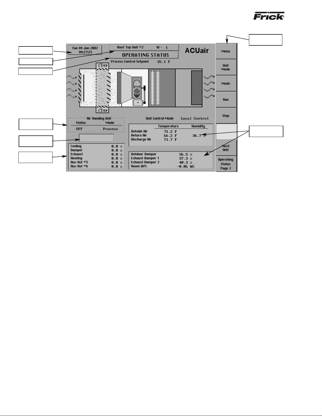
UNIT SELECTED - "OPERATING STATUS" SCREEN
Date and Time
Unit Name
Screen Title
Air Handling
Unit Data Box
Alarm Status
Box
Demand Output
Box
The most important information about the unit is displayed
here. In the middle of the screen is a diagram of an
ACUair® unit that shows the current state of the unit. The
supply fan and both exhaust fans spin, a flame is
displayed when the burner is on, and the cooling coils are
colored blue when they are open and white when they are
closed. The outside air dampers, the return air dampers,
and both exhaust dampers are drawn to match the state
of the dampers on the ACUair® unit.
Above this diagram, the Process Control Setpoint is
displayed. This setpoint is maintained when the unit is in
Process Mode. To the right of this setpoint, the word
"Economizer" is displayed when the Economizer
conditions are met. Below the diagram, the Unit Control
Mode is displayed. When in Local Control Mode the unit is
controlled from the Quantum™ Interface panel. When it is
set to Remote Control mode the unit can be turned on and
off and toggled between Process and Cleanup at the unit
itself.
The following information is shown on the left side of this
screen:
AIR HANDLING UNIT DATA BOX:
Shows the present operating status of the unit:
· Status - One of the following messages is
shown:
· Off
· Running
· Starting - The unit has turned on but air flow
has not been detected.
· Mode - One of the following messages is shown:
· Process – The unit is maintaining optimum
air conditions for processing product.
· Cleanup - The unit is modifying air
conditions to support the cleanup procedure.
Operator
Selection Ke
Analog
Readings Box
s
ALARM STATUS BOX:
The alarm status is displayed in the indented box
below the air handling unit data box. The status box
is blank with no message if there are no alarms
present.
The following message could be shown:
· ALARM - This message flashes when an alarm
is present. An alarm is a condition that requires
an operator to acknowledge it and allows the unit
to continue its operation.
· SHUTDOWN - This message flashes when the
unit is in a shutdown condition. During a
shutdown situation, the unit remains off until an
operator acknowledges the shutdown and
restarts the unit.
An Alarm message indicates an Alarm point has been
reached or exceeded. Select the [Alarms/Shutdown]
key from the "Main Menu" screen for details. For
additional shutdown information, select the
[Alarms/Shutdown] key from the "Main Menu"
screen and then the “Alarms/Shutdowns History”
screen.
DEMAND OUTPUT BOX:
The bottom box on the left side of the screen holds
the demand control values. These values range from
0 - 100% and are the results of PID calculations.
Larger percentages indicate that input readings have
moved away from setpoint and increased air
modification is necessary.
The following demand values are shown:
· Cooling
· Damper
· Exhaust
· Heating
· Aux. Output #5
· Aux. Output #6
FRICK® QUANTUM™ ACUair® CONTROL PANEL S90-500 O
OPERATION Page 9
ANALOG READINGS BOX:
The following analog input readings are possible.
They are shown if they were enabled during the
board setup.
· Outside Air Temperature
· Room/Return Air Temperature
· Discharge Air Temperature
· Coil Air Temperature
· Humidity
· Outdoor Damper
· Exhaust Damper 1
· Exhaust Damper 2
· Room Differential
UNIT SELECTED - "OPERATING STATUS - 2" SCREEN
Screen Title
Date and Time
Unit Name
ACUair® Input
Status Box
OPERATOR SELECTION KEYS
Following are the screen key selections for the
"Operating Status" screen:
· [Menu] – Shows the “Main Menu” screen for the
selected Unit.
· [Unit Mode] – The following control mode can be
selected:
· [Remote] – The unit is turned on and off and
set to either Process or Cleanup Mode
through digital inputs. The unit can be
returned to local mode by pressing the
"Mode", "Run" or "Stop" buttons.
· [Mode] – Toggles the unit between Process and
Cleanup Mode.
· [Run] - Starts the unit if it is currently stopped.
· [Stop] - Turns the unit off.
· [Operating Status Page 2] - Shows the
“Operating Status - 2” screen.
Operator
Selection Keys
Unit ID
ACUair Output
Status Box:
First Block
Sensor
Indication
Defrost Status
Box
The Operating Status – page 2, displays additional
information that cannot be shown on the first Operating
Status screen. Along the left side of the page is the Input
Status Box while on the right side of the page is the
Output Status Box. Below these boxes, the current
Ammonia reading and other sensor values may be
displayed if they are enabled.
ACUair® INPUT STATUS BOX:
The present operating status of the digital inputs is shown.
One of the following messages is displayed:
· On – The input is energized or turned on.
· Off - The input is de-energized or turned off.
The following inputs are shown in the first block (if they
were enabled during the board setup).
Second Block
Third Block
Additional
Analog Outputs
· Remote Start/Stop
· Burner Status
The following inputs are shown in the second block (if
they were enabled during the board setup).
· Flame Failure
· Demand Defrost
· Smoke/Ammonia
· Burner Status (Aux. 2)
ACUair® OUTPUT STATUS BOX:
The present operating status of the digital outputs is
shown. One of the following messages is displayed:
· On – The output is energized or turned on
· Off - The output is de-energized or turned off.
· Air Flow Switch
· Remote Process/Cleanup
FRICK® QUANTUM™ ACUair® CONTROL PANEL S90-500 O
OPERATION Page 10
The following outputs are shown in the first block (if they
were enabled during the board setup):
· Supply Fan Motor
· Exhaust Fan #1
· Exhaust Fan #2
· Burner Command
The following outputs are shown in the second block (if
they were enabled during the board setup):
· Cooling Stage #1
· Cooling Stage #2
· Cooling Stage #3
· Cooling Stage #4
The following outputs are shown in the third block (if they
were enabled during the board setup):
· Preheat Command
UNIT SELECTED - "MAIN MENU" SCREEN
· Suction
· Hot Gas
· Bleed
The following outputs are shown in the Additional Analog
Outputs block (if they were enabled during the board
setup):
· Aux. Output #7
· Aux. Output #8
SENSOR INDICATION:
The current values of all the analog inputs that have been
selected and installed are shown.
DEFROST STATUS BOX:
If Defrost has been enabled, the current status of the
Defrost cycle is shown.
SCREEN KEY SET
The "Main Menu" screen provides a selection of screen
keys to guide the operator through all the screens. The
following are descriptions of each screen selection and a
listing of further selections:
· [Operating Status] - Shows the "Operating
Status" screen.
· [Alarms/Shutdowns] - Shows the Alarms /
Shutdowns" screen which shows in red text the
current Failures, and the Date, and Time of the
Failure. The following selections are available:
· [Clear Alarms]
· Alarms/Shutdowns History Screen
· [Control Setup] - Shows the "Control Setup"
menu screen. The following items are selections:
· [Cooling Control]
· [Heating Control]
· [Preheat Control]
· [Exhaust Control]
· [Damper Control]
· [Humidity Control]
· [Safety Setpoints]
· [Defrost]
· [Variable Fan]
· [Analog Aux. Input]
· [Analog Aux. Output]
· [Calibration] - Shows the "Analog calibration"
screen. From this screen, the following
calibrations can be selected:
· Change Temperature Probe Types, Ranges
and Offsets
· Calibrate Miscellaneous Sensors

FRICK® QUANTUM™ ACUair® CONTROL PANEL S90-500 O
OPERATION Page 11
MAIN MENU SELECTION - "ALARMS/SHUTDOWNS" SCREEN
The following are the "Alarms/Shutdowns" screen
selection keys:
· [Clear Alarms] - Selecting this key will clear all
alarms and/or shutdowns from this screen.
· [Alarms/Shutdown History] - A full screen of
failures is stored, along with the Last Fail
Date/Time of the failure. The stored data shows
on the "Alarms/Shutdowns History" screen. The
data is saved, even if there is a power outage.
To resume normal operation it will be necessary to go
through the following steps:
1. Correct the conditions causing the alarm.
MAIN MENU SELECTION - "ALARMS/SHUTDOWNS HISTORY" SCREEN
2. To clear or reset the "Alarms/Shutdowns" screen
and turn off any alarm annunciation device, from
the screen press the [Clear Alarms] key. This
will also clear the “ALARM” or “SHUTDOWN”
message from the "Operating Status" screen.
3. If the conditions causing the alarm have not been
corrected or a new fault has occurred, a new
“ALARM” or “SHUTDOWN” message will appear.
The Alarms/Shutdowns history screen keeps a
record of the alarms and shutdowns. This
information will help troubleshoot persistent
Refer to the "Alarms/Shutdowns Message" section for a
list of all the possible alarms.
operational problems.
 Loading...