

Page 1

S90-010 CS/APR 2008
File: SERVICE MANUAL - SECTION 90
Replaces: S90-010 CS/APR 04
Dist: 3, 3a, 3b, 3c
COMMUNICATIONS SETUP
FRICK® QUANTUM™
COMPRESSOR
CONTROL PANEL
VERSION 5.0x
Page 2

®
S90-010 CS (APR 08) FRICK
Page 2 COMMUNICATIONS SETUP
QUANTUM™ COMPRESSOR CONTROL PANEL
Table of Contents
QUANTUM™ IDENTIFICATION _______________________________________________________4
Setting Up the Quantum™ for Communication ________________________________________________ 4
Com-2 Pinouts for Quantum™ 3 ________________________________________________________ 4
Com-2 Pinouts for Quantum™ 4 ________________________________________________________ 4
RS-232 Communications _________________________________________________________________ 5
Quantum™ 3 _______________________________________________________________________ 5
Quantum™ 4 _______________________________________________________________________ 5
Converting an RS-232 Serial Port to RS-422 or RS-485 _________________________________________ 5
Change Communications_________________________________________________________________ 6
COMMUNICATIONS LOOPBACK TEST ________________________________________________7
Hardware Setup for RS-422 Testing ________________________________________________________ 7
Hardware Setup for RS-485 Testing ________________________________________________________ 7
Software Setup For The Communications Loopback Test________________________________________ 8
Performing the Communications Loopback test________________________________________________ 8
PROTOCOL DESCRIPTION__________________________________________________________9
Quantum™ Communications Protocols ______________________________________________________ 9
Checklist For Setting Up Communication _________________________________________________ 9
®
Protocols _______________________________________________________________________ 11
Frick
Quantum™ $ Protocol Specifications_______________________________________________________ 15
®
# Protocol Specifications ________________________________________________________ 11
Frick
Data Packet _______________________________________________________________________ 15
CONVERSION CHART FOR DECIMAL / HEXADECIMAL / ASCII ___________________________ 23
ALLEN-BRADLEY COMMUNICATION ________________________________________________24
SLC-500 - Suggested Setup _____________________________________________________________ 24
Channel Configuration _______________________________________________________________ 24
Read Message Setup Example ________________________________________________________ 25
Write Message Setup Example ________________________________________________________ 25
PLC-5/30 - Suggested Setup _____________________________________________________________ 25
Channel Configuration _______________________________________________________________ 25
Read Message Setup Example ________________________________________________________ 26
Allen-Bradley Programming Overview ______________________________________________________ 26
Channel Configuration _______________________________________________________________ 26
General Configuration __________________________________________________________________ 26
System Configuration___________________________________________________________________ 26
Message Sequence Logic _______________________________________________________________ 27
Message Read Logic ___________________________________________________________________ 27
Message Read Setup Screen _________________________________________________________ 28
Message Write Logic ___________________________________________________________________ 29
Message Write Setup Screen _________________________________________________________ 30
MODBUS Protocol ________________________________________________________________ 31
Port Configuration of The Master __________________________________________________________ 31
Data Packet __________________________________________________________________________ 31
The Query ___________________________________________________________________________ 32
The Response ________________________________________________________________________ 32
Data Field____________________________________________________________________________ 32
Error Checking ________________________________________________________________________ 32
ASCII Framing ________________________________________________________________________ 32
Query (Read) Example__________________________________________________________________ 33
Write Example ________________________________________________________________________ 34
Response Example ____________________________________________________________________ 36
Modbus Notes ________________________________________________________________________ 37
YORK ISN DATA ACCESS _________________________________________________________38
Page 3

®
FRICK
QUANTUM™ COMPRESSOR CONTROL PANEL S90-010 CS (APR 08)
COMMUNICATIONS SETUP Page 3
HYPERTERMINAL ________________________________________________________________41
Setting up Hyperterminal_________________________________________________________________41
Testing Communications_________________________________________________________________ 46
General Notes _________________________________________________________________________46
QUANTUM™ DATA TABLE _________________________________________________________48
Allen-Bradley and Modbus Data Access _____________________________________________________ 48
Modbus Addressing Note _____________________________________________________________48
ALARMS/SHUTDOWNS MESSAGE CODES ___________________________________________71
QUANTUM™ 3 MAIN BOARD HISTORY AND IDENTIFICATION ___________________________73
Quantum™ 3 Main Board Photo ___________________________________________________________73
Quantum™ 3 Communications Jumpers_____________________________________________________74
Communications Board Jumpers _______________________________________________________ 74
Com-1_________________________________________________________________________74
Com-2_________________________________________________________________________74
Communications WIRING_____________________________________________________________ 74
QUANTUM™ 4 MAIN BOARD HISTORY AND IDENTIFICATION ___________________________75
Quantum™ 4 Main Board Photo ___________________________________________________________75
Quantum™ 4 Communications Jumpers_____________________________________________________76
Communications Board Jumpers _______________________________________________________ 76
Com-1 (TB1)____________________________________________________________________76
Com-2 (TB2 - TB3)_______________________________________________________________76
Communications Wiring ______________________________________________________________76
COMMUNICATIONS WIRING DIAGRAMS _____________________________________________77
To Customer Remote Computer/Dcs _______________________________________________________77
RS-485 Communications _____________________________________________________________77
RS-422 Communications _____________________________________________________________77
Multicompressor Sequencing (Lead-Lag) ____________________________________________________77
RS-485 Communications _____________________________________________________________77
RS-422 Communications _____________________________________________________________77
CONNECTIONS __________________________________________________________________78
INDEX __________________________________________________________________________80
The Quantum™ has the capability of being modified by the user/owner in order to obtain different performance characteristics.
Any modification to the standard default settings may have a severe negative impact on the operation and performance of the
equipment. Any modification to these control settings is the sole responsibility of the user/owner and Frick
liability for the consequences of these modifications. It is possible that the modification of these settings may cause improper
operation and performance that results in property damage, personal injury or death. It is the responsibility of the user/owner
to evaluate and assess the consequences of their actions prior to modifying the controls for this unit.
WARNING
!
®
disclaims any
Page 4
®
S90-010 CS (APR 08) FRICK
QUANTUM™ COMPRESSOR CONTROL PANEL
Page 4 COMMUNICATIONS SETUP
Frick
QUANTUM™ IDENTIFICATION
®
Controls has over the years, strived to remain on
the cutting edge of microprocessor technology and
development. Because of the ever-increasing speed,
memory, features, and power of microprocessors, Frick
®
Controls will continue to introduce the latest advancement
in microprocessor control technology.
Our microprocessor family has shared the name
Quantum™, over the past five years. There are currently
four controllers within this family. The first two of these
controllers (known as Quantum™ 1 and Quantum™ 2) are
no longer in production, and as such, will not be further
mentioned in this manual. The two current members in
production of the Quantum™ family are the Quantum™ 3,
and the Quantum™ 4. It is critical to the end user to be
able to identify the differences between these controllers.
Refer to the section in this manual entitled Quantum™ 3
Main Board History and Identification and Quantum™ 4
Main Board History and Identification for additional
information as to how to identify the particular Quantum™
controller that you have.
Throughout this manual, the two different controllers will
be talked about for the most part as one (as they do
function the same). Where there is a difference between
these boards, as in jumpers or wiring, the different models
will be identified by name. This is why it is important for
you to be aware of which Quantum™ board you have.
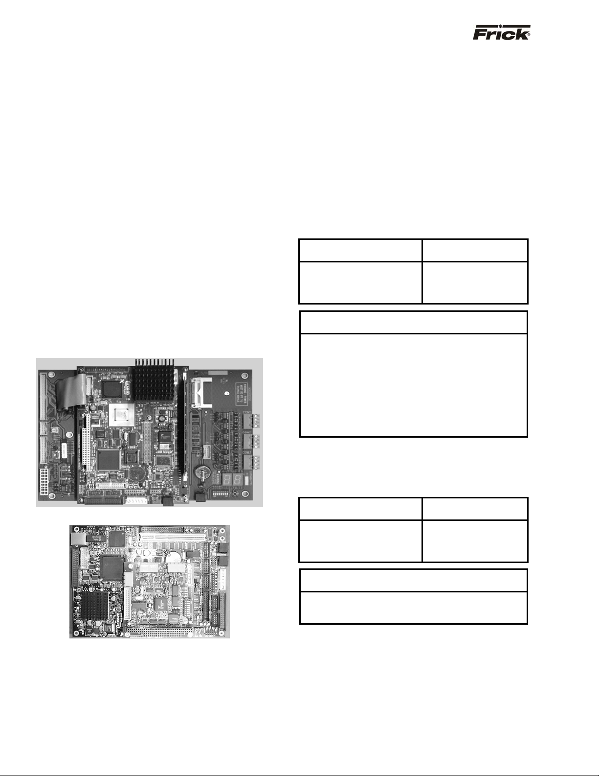
Quantum™ 3
Quantum™ 4
Setting Up the Quantum™ for
Data communication to and from the Quantum™ can be
through a modem, remote data communications terminal,
programmable controller, or master computer via either
RS-422, RS-232, or RS-485 connections to the
Quantum™ Com-2 port. Reference the Main Board
Communications section for the correct jumpering of RS422, RS-232, or RS-485. Also, reference the drawing of
the Quantum™ Main Board section to identify wiring
configurations for Com-2.
COM-2 PINOUTS FOR QUANTUM™ 3
Following is the RS-422, RS-485, and the RS-232 pin
descriptions for communications port 2 (also referred to as
Com-2 or Comm-2):
RS-422 Pinout
(4-Pin Connector)
1 - RX (Receive) 1 - RX / - TX
2 + RX (Receive) 2 + RX / + TX
3 - TX (Transmit)
4 + TX (Transmit)
1 Data Communication Device
2 Data Set Ready
3 Received Data
4 Request to Send
5 Transmit Data
6 Clear to Send
7 Data Terminal Ready
8 Ring Indicator
9 Ground
10 Not Used
COM-2 PINOUTS FOR QUANTUM™ 4
Following is the RS-422, RS-485, and the RS-232 pin
descriptions for communications port 2 (also referred to as
Com-2 or Comm-2):
RS-422 Pinout
(4-Pin Connector)
1 - RX (Receive) 1 - RX / - TX
2 + RX (Receive) 2 + RX / + TX
3 - TX (Transmit)
4 + TX (Transmit)
1 Transmit Data
2 Received Data
3 Ground
Communication
RS-485 Pinout
(4-Pin Connector)
RS-232 Pinout
(10-Pin Connector)
RS-485 Pinout
(4-Pin Connector)
RS-232 Pinout
(3-Pin Connector)
Page 5
®
j
(
FRICK
QUANTUM™ COMPRESSOR CONTROL PANEL S90-010 CS (APR 08)
COMMUNICATIONS SETUP Page 5
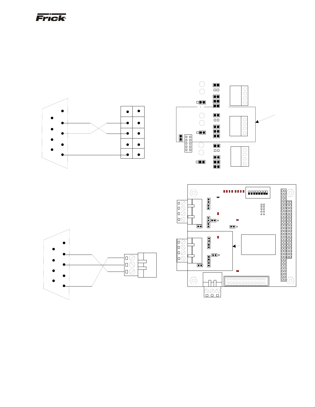
RS-232 Communications
Following is the pin connections showing how to wire a
standard 9-Pin RS-232 connector directly to the 10-Pin
RS-232 connector on the Quantum™ 3, and the 3-pin
connector on the Quantum™ 4:
QUANTUM™ 3
Reference the drawing of the main processor board for the
location and positioning of the 10-Pin RS-232 connector.
Following is the pin positions of the 10-Pin connector:
9-Pin
Connector
1
6
2
7
3
8
4
9
RXD RXD
TXD
COM COM
Quantum™ 3
10-Pin Connector
1 2
TXD
10
Note: The TX2 and RX2 are I/O communication activity
lamps on the Quantum™ Main Processor Board that can
be monitored to see if the Com-2 port is receiving (RX2)
and transmitting (TX2) data.
QUANTUM™ 4
Reference the drawing of the main processor board for the
location and positioning of the 3-Pin RS-232 connector.
Following is the pin positions of the 3-Pin connector:
9-Pin
Connector
1
6
2
7
3
8
4
9
5
RXD
TXD
COM
Quantum™ 4
3-Pin Connector
3
COM
TXD
1
Converting an RS-232 Serial Port to RS-422 or
In order to communicate to the Quantum™ controller via
RS-422 (or RS-485), you will need to convert the RS-232
signal from the source.
One converter that has proven to be effective is the Opto22 AC7A/B card. This card will allow the conversion from a
standard RS-232 signal to either RS-422 or RS-485. The
AC7A card is powered from a 115 VAC source, while the
AC7B card is powered from a 220 VAC source. They can
be used in a standalone panel along with an Allen Bradley
SLC 5/04 or along with an external modem. Keeping the
jumpers installed the same way they are received from the
factory, it is easy to wire for either RS-422 or RS-485.
RS-485
NOTE: Refer to the manual that comes with the AC7A/B
card for specific jumper information (as the configuration
shown is only a suggestion that has worked in most
applications).
Once jumpers on the converter card have been verified,
you will need to verify the jumper settings of the
Quantum™ controller. Refer to the following diagrams for
the Quantum™ 3 and Quantum™ 4:
COM-2
RS-232
LK19
RX1
TX1
B
A
RX2
TX2
B
A
RX3
TX3
LK18
B
A
LK16
LK17
LK1
LK2
LK3
LK4
LK5
LK6
LK7
LK8
LK9
LK10
LK11
LK12
LK13
LK14
LK15
COM-1
RS-422/RS-485
1 2 3 4
COM-2
RS-422/RS-485
1 2 3 4
COM-3
Future Use)
1 2 3 4
Verify the
umpers in this
location.
Quantum™ 3
COM-1
RS-422
RS-485
COM-2
RS-422
RS-485
TB1
TB2
COM-2
RS-232
4 3 2 1
4 3 2 1
LK1
LK8 LK7
TB3
3 2 1
LK10 LK9
LK6 LK5
LK4 LK3
PORT
D5
D4
D7
D3
D2 D1
LK16
O
D8
D13
D11
D12
D10
D6
B
A
LK11
jumpers in this
B
A
LK17
D8
DIP
1 2 3 4 5 6 7 8
Verify the
location.
PL2
SW1
PL1
PL4
PL3
0
1
4 5 6
7
2
3
Quantum™ 4
NOTE: Some of these jumper settings may need to be
modified to ensure optimum communications
performance. Typically, the termination jumper should be
installed in the last Quantum™ in the communications
daisy chain only (Link 7 for the Quantum™ 3, Link 1 for
the Quantum™ 4).
Page 6

®
S90-010 CS (APR 08) FRICK
QUANTUM™ COMPRESSOR CONTROL PANEL
Page 6 COMMUNICATIONS SETUP
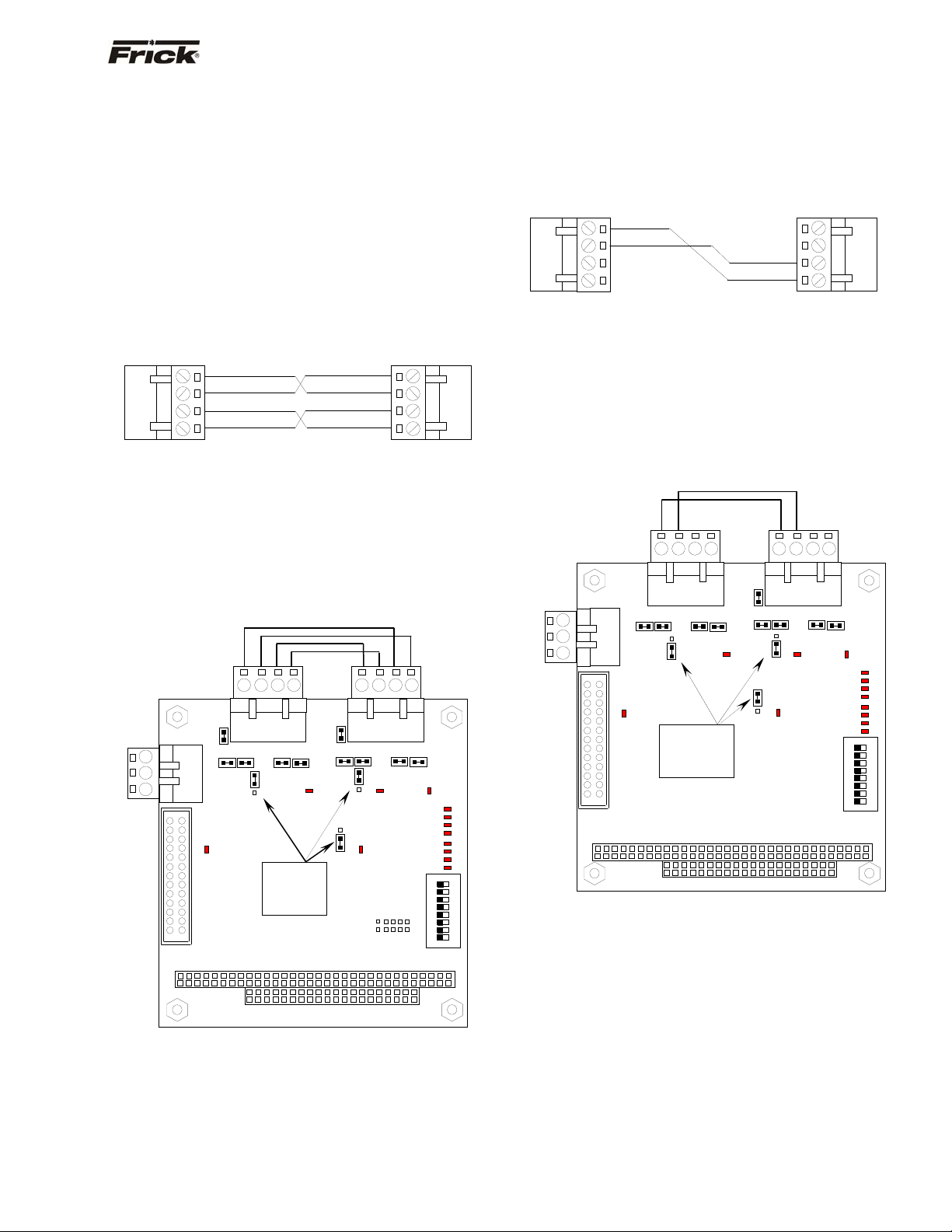
After verifying both the Converter card and Quantum™
jumper settings, the interconnecting wiring must be done.
Be sure to use 4-conductor shielded communications
cable (two wires for transmit, two for receive). Refer to the
following diagrams for RS-422 and RS-485:
4-Pin
connector
1
2
3
4
Quantum
™
COM-2
-RX
+RX
-TX
+TX
Hard wire
TO-
TO+
FO-
FO+
RS-422 To RS-232
25-Pin Male
connector
2
3
7
AC7A
Converter
RXD
TXD
CTS
9-Pin Female
connector
RXD
2
TXD
3
RTS
5
RS-232
Computer
Port
RS-422
4-Pin
connector
1
2
3
4
Quantum
™ COM-2
-RX/-TX
+RX/+TX
Hard wire
TO-
TO+
FO-
FO+
RS-485
25-Pin Male
connector
2
3
7
AC7A
To RS-232
Converter
RXD
TXD
CTS
9-Pin Female
connector
RXD
2
TXD
3
RTS
5
RS-232
Computer
Port
RS-485
Change Communications
We have used both an Opto 22 AC7A/B and an Opto 22
AC422 adapter card. They can be wired to use either RS422 or RS-485.
Following is the pin connections showing how to wire a
DB9 connector on this adapter card to the Quantum™ for
RS-422 communication:
Quantum™ COM-2 DB9
1 5
2 4
3 9
4 8
Following is the pin connections showing how to wire for
RS-485 to the terminal connections on this adapter card
from the Quantum™:
Quantum™ Terminal
1 (-RX/-TX) FO-
2 (+RX/+TX) TO+
The card can be connected RS-232 to another device.
Following is the pin connections showing how to wire the
25-Pin RS-232 connector on this adapter card to a 9-Pin
connector of the SLC 5/04:
DB9 DB25
5 7
2 3
3 2
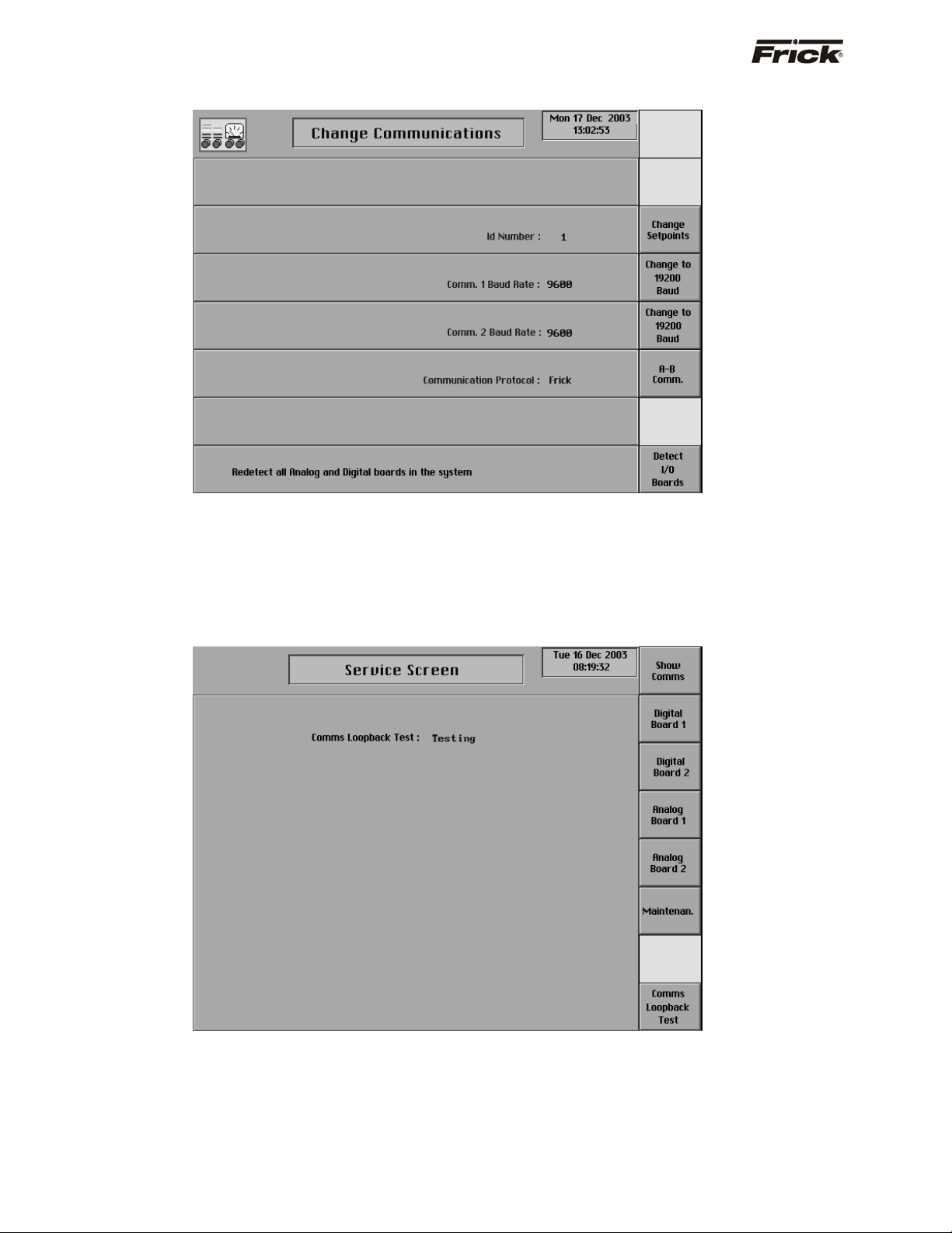
This screen is accessed by pressing the [Change
Comms.] key on the Panel Setup screen.
The following information is shown here:
• ID Number
• Comm. 2 Baud Rate
• Communication Protocol
• Comm. 1 Baud Rate
Page 7
®
T
T
QUANTUM™ COMPRESSOR CONTROL PANEL S90-010 CS (APR 08)
FRICK
COMMUNICATIONS SETUP Page 7
COMMUNICATIONS LOOPBACK TEST
With version 5.0x Quantum™ software, a method of
testing the onboard RS-422 and RS-485 communications
ports was developed. By utilizing a loopback test harness
(as shown below), the maintenance technician now has
the ability to locally test the Quantum™ communications
hardware and jumper configuration.
Hardware Setup for RS-422 Testing
To create the test harness for RS-422 communications
loopback testing, use the following example:
1
-
+RX
-TX
+TX
4
-
Set the Quantum™ 4 communications jumpers as follows:
• Set LK11 to position B
• Set LK16 to position A
• Set LK17 to position A
• Plug the RS-422 test harness (as shown above)
into the com ports at TB1 and TB2 as shown
here:
COM-2
RS232
3
2
1
TB3
1 2 3
LK1
RS-422/RS-485
LK4 LK3
COM-2
LK17
4
TB2
TB1
LK2
LK7
LK6 LK5
A
B
D8
Verify the
LK11
jumpers in
these
locations.
PL1
RS-422 Test Configuration
4-Pin Connector4-Pin Connector
+TX
-TX
+RX
-RX
1 2 3
COM-1
RS-422/RS-485
LK8
A
B
D2D1
LK16
B
A
D6
PL2
4
1
4
LK10LK9
D3
POR
0
D4
1
D5
2
D7
3
D8
4
D10
5
D11
6
D12
7
D13
1
ON
2
3
4
5
6
7
DIP
8
SW1
Hardware Setup for RS-485 Testing
To create the test harness for RS-422 communications
loopback testing, use the following example:
4-Pin Connector
1
-RX/-TX
4-Pin Connector
4
4
-
-RX/-TX
1
Set the Quantum™ 4 communications jumpers as follows:
• Set LK11 to position B
• Set LK16 to position B
• Set LK17 to position B
• Plug the RS-485 test harness (as shown above)
into the com ports at TB1 and TB2 as shown
here:
COM-2
RS232
3
2
1
PL1
TB3
LK1
LK3
D8
12 3
COM-2
RS-422/RS-485
LK4
A
B
LK17
Verify the
jumpers in
these
locations.
4
LK6 LK5
123
TB1 TB2
LK2
RS-422/RS-485
LK8 LK7
A
B
LK16
B
A
D6
LK11
COM-1
D2D1
PL2
4
LK10LK9
D3
POR
0
D4
1
D5
2
D7
3
D8
4
D10
5
D11
6
D12
7
D13
1
ON
2
3
4
5
6
7
DIP
8
SW1
RS-485 Test Configuration
Page 8
®
S90-010 CS (APR 08) FRICK
QUANTUM™ COMPRESSOR CONTROL PANEL
Page 8 COMMUNICATIONS SETUP
Software Setup For The Communications Loopback Test
On the Change Communications screen (shown above),
ensure that the settings are as follows:
• ID Number: 0 - 99 (does not matter)
• Comm 1 Baud Rate: (does not matter, but it must
be set the same as Comm 2 Baud Rate)
Performing the Communications Loopback test
• Comm 2 Baud Rate: (does not matter, but it must
be set the same as Comm 1 Baud Rate)
Communication Protocol: Frick® (must be Frick®)
Upon properly setting up the Change Communications
screen, access the Service Screen. The center of the
screen will initially appear blank. The bottom key on the
right side of this screen is the Comms Loopback Test key.
Pressing the key will initiate the test. The blank center of
the screen will be replaced by one of three word lines:
• Testing - This will appear as the test is running.
NOTE: The test occurs so quickly that It may be
possible that the word Testing will not appear if
the test passes.
• Passed - If the test passes, the word Passed will
appear.
• Failed - If the test does not pass, this will appear.
Page 9

®
QUANTUM™ COMPRESSOR CONTROL PANEL S90-010 CS (APR 08)
FRICK
COMMUNICATIONS SETUP Page 9
PROTOCOL DESCRIPTION
The use of communication protocols, permits data
transmission between devices. Protocol determines how
contact is established and how the query (question) and
response (answer) takes place. The information in a
message command requires an identity of the intended
receiver (ID #), what the receiver is to do (read or write to
a setpoint, etc.), data needed to perform an action (the
value of a setpoint to be changed), and a means of
checking for errors (checksum).
When using Com-2 for communication, check what
communication protocol, if any has been selected, from
the Panel Setup – Change Communications screen. For
example, [A-B Comm] should be selected when using
Allen-Bradley’s communication protocol. The baud rate of
Com-2 and the panel ID number are also changed from
this screen, and should coincide with the setup of the
other device.
Note: The data communication protocols are continuously
being expanded and improved. Therefore, you should
consult Frick
®
Controls for the exact details on your
particular unit(s) before developing system software to
interface with the panel.
Quantum™ Communications Protocols
The Quantum™ controller has the capability of
communicating to the outside world through four software
protocols:
• Frick
®
• Allen-Bradley DF-1 serial
• ModBus ASCII serial
• YORK ISN
Note: When using Modbus protocol, a [Comm. 2
Advanced] key will appear. Pressing this key will
allow the user to modify the number of Data and Stop
bits, as well as Parity. This only applies to Modbus.
Modbus cannot be changed from ASCII to RTU
however. Refer to the section on Modbus for further
information.
Checklist For Setting Up Communication
0191 Decide which Quantum™ protocol you
can communicate with and want to use.
0191 Setup your device’s communication port
for the Quantum™ protocol and select a baud
rate.
Protocols
0191 Next, setup the Quantum™ for the desired
communication protocol. Select the protocol from
the Panel Setup – Change Communications
screen. For example, [A-B Comm] should be
selected when using Allen-Bradley’s
communication protocol.
0191 Setup the baud rate of Com-2 to coincide
with the setup of the your device’s
communication port.
0191 Enter the Quantum™ ID. This will be used
to identify commands that are sent to it.
0191 Wire to the first panel via RS-232, RS-
422, or RS-485 connections to the Quantum™
Com-2 port.
• If you are communicating to more than one
panel, then you will not be able to use RS-
232. You can however, convert RS-232 to
either RS-422 or RS-485 with an adapter
card. Reference the Converting an RS-232
Serial Port to RS-422 or RS-485 section for
information about an adapter card.
Page 10

®
S90-010 CS (APR 08) FRICK
QUANTUM™ COMPRESSOR CONTROL PANEL
Page 10 COMMUNICATIONS SETUP
• Reference the drawing of the Quantum™
Main Board in this manual to identify wiring
and jumpering locations for Com-2.
• Reference the Main Board Communications
Com-2 section in this manual for the correct
jumpering of RS-232, RS-422, or RS-485.
0191 Send a single command to read data from
this Quantum™ using its ID.
0191 Check if you received a data response at
your device.
0191 Troubleshooting when you don’t receive a
data response:
• Check if Com-2 on the Operating Status
screen is showing ACTIVE or OFF.
• ACTIVE is shown only when the Quantum™
understands it is receiving a properly
composed message to itself.
• Check that the RX2 I/O communication
activity lamp on the Quantum™ Main
Processor Board is blinking as it receives the
instruction from your device.
• A steady lit RX2 LED or one that isn’t
lighting, are signs of improper wiring.
• If the RX2 LED is properly blinking, then
check if the TX2 LED is blinking in response.
• If the TX2 is not blinking then check the
communication protocol setup at the panel,
the panel’s ID and the Com-2 baud rate
setting.
• If the TX2 is blinking, then check that the
Com-2 communication jumpers are correct.
• If you are sure that the wiring and
Quantum™ setup is correct, then select the
[Show Comms] key from the Service
Screen to see what is being received and
transmitted from Com-2.
Note: A useful tool for troubleshooting is Windows
HyperTerminal. Using HyperTerminal can help you
determine if you are wired OK. Reference the
HyperTerminal Setup section in this manual.
0191 If you properly receive data and you need
to communicate to more than one panel, then
setup and wire to another panel. Reference the
wiring diagram drawings in the back of this
manual. Send a single command to read data
from this Quantum™ using it’s ID and
troubleshoot as above, if necessary. To prevent
noise feedback which is possible when
communicating over a long distance, only the last
panel should have the termination for long
communications lines jumpered.
Page 11

®
QUANTUM™ COMPRESSOR CONTROL PANEL S90-010 CS (APR 08)
FRICK
COMMUNICATIONS SETUP Page 11
Frick® Protocols
All commands for Frick® protocols must be in ASCII to be
recognized (see the Conversion Chart For Decimal /
Hexadecimal / ASCII, located later in this manual). The
data should be setup as an 8 bit Word with no Parity, and
a Stop Bit. The commands can be in upper or lower case
letters. A compressor with an ID code of [00] is considered
disabled. ID codes from [01] through [99] are valid and
recognized by the microprocessor.
Frick® # Protocol Specifications
Frick® # protocol consists of commands that are available
for most other existing models of Frick control panels. The
®
Frick
# protocol does not utilize a checksum. It is better to
use Frick
communicating to Quantum™ panels.
®
Quantum™ ($) protocol when only
When there is more than one panel, a Quantum™ can be
wired from it’s Com-2 to another panels Com-2 or can be
wired from it’s Com-2 to Port 1 of a RWB, RDB, RXB or
RXF Micro Plus panel.
Frick® RWB, RDB, RXB, or RXF Panel Frick® #
Communications Port #1
RS-422 Pinout
9 - TX (Transmit)
8 + TX (Transmit)
5 - RX (Receive)
4 + RX (Receive)
The following is a complete list of available Frick® Protocol
# commands:
COMMAND CODE and DESCRIPTION
I = Returns compressor status information.
R = Compressor start control.
S = Compressor stop control.
V = Slide Valve/Slide stop control.
P = Return Pressures information.
A = Return full load amps information.
T = Return Temperatures information.
Q = Query setpoints data.
C = Enter Change setpoints mode.
MC = Change compressor mode.
MV = Change Slide Valve mode.
KF = Clear Failures.
KR = Clear remaining recycle delay time.
X = Return digital I/O status.
F = Return Failures.
All data is returned as integer values. If decimal positions
are assumed, then divide the data by the proper multiple
of 10 to get the actual value.
Temperature data, except for Suction Temperature, is
returned in the current temperature units as 3 characters
with no decimal position (i.e. 032 would represent 32
degrees Fahrenheit if the panel temperature units are in
Fahrenheit, or it would represent 32 degrees Celsius, if the
panel temperature units are in Celsius). Suction
Temperature is returned as 4 characters with a + or - as
the leading character (i.e. –010 would represent –10
degree).
Pressure data is usually returned in the current pressure
units. However, the Filter differential reading is always
returned in PSIA. When in PSIG or in PSIA, the pressure
data is returned as 3 characters with no decimal position.
However; in order to show the full transducer range, the
#IDPS command returns 4 characters with one decimal
position assumed. The #IDI, and #IDPA commands return
3 characters that assume one decimal position; therefore,
99.9 is the highest value that can be returned. When in
PSIG, suction pressure is returned in PSIA. When in Bar
and BarA, the pressure data is returned as 4 characters
with two decimal positions assumed. When in KpaA, the
pressure data is returned as 4 characters with no decimal
position.
The following is a detailed description of each command:
RETURN COMPRESSOR STATUS INFO: #01I
# Start of command sequence.
01 Compressor ID code.
I Return Status information command.
RETURNED ANSWER, ie: 090RRRN340
Character
Position
Description
of returned data
1, 2, 3 Slide Valve position.
4 Remote, Auto, Manual (Slide Valve)
5 Delay-recycle, Running, Off, Slide Valve
too high, Permissive Start not enabled,
d(I)fferential Pressure too high, s(T)opping,
au(X) not energized
6 Rem, M Keypad, Auto (Compressor mode)
7 Cutout (Shutdown), Alarm, Normal
8, 9, 10 Suction in PSIA.
(Carriage return, line feed.)
Note: The following control commands are for remote
control of a compressor. A compressor should be in both
remote compressor mode and remote Slide Valve or
capacity mode for remote control.
COMPRESSOR START CONTROL: #01R01
# Start command sequence.
01 Compressor ID code.
R Start compressor command.
01 ID code repeated for verification
NOTE: The compressor must be in the remote Start
mode for this command to be executed.
Returned answer: A01
Character
Position
Description
of returned data
1 Acknowledge of command sent.
2, 3 ID code of compressor.
(Carriage return, line feed.)
Page 12

®
S90-010 CS (APR 08) FRICK
QUANTUM™ COMPRESSOR CONTROL PANEL
Page 12 COMMUNICATIONS SETUP
COMPRESSOR STOP CONTROL: #01S01
Returned in the current temperature units as 3
characters with no decimal position (i.e. 032 would
represent 32 # Start command sequence.
01 Compressor ID code.
S Stop compressor command.
01 ID code repeated for verification
NOTE: The compressor must be in the remote
Start mode for this command to be executed.
RETURNED ANSWER: A01
Character
Position
Description of returned data
1 Acknowledge of command sent.
2,3 ID code of compressor.
(Carriage return, line feed.)
SLIDE VALVE CONTROL COMMANDS: #01VLXX
#01VUXX
#01VS
# Start command sequence.
01 Compressor ID code.
V Slide Valve/Slide Stop command.
L Load Slide Valve command.
U Unload Slide Valve command.
XX = 00 Turns selected output off.
XX = 01 to 15 Turns selected output on for XX seconds.
S Return Slide Valve position value.
If the command was #01VL00, then the load Slide
Valve output on compressor #1 would be turned off. If
the command was #01VL05, then the load Slide Valve
output on compressor #1 would be turned on for 5
seconds, and would then automatically turn off. NOTE:
RETURN PRESSURES COMMAND: #01PX
# Start command sequence.
01 Compressor ID code.
P Return pressures command.
X = S Return suction Pressure (PSIA).
X = D Return discharge Pressure (g/hg).
X = O Return oil Pressure (g).
X = F Return filter differential Pressure.
X = A Return all pressures.
If the command was #01PS, then the micro-processor
would dump the suction Pressure.
Note: Don’t send CR or LF
RETURNED ANSWER:
XXX = 3 characters followed by a carriage return, line
feed.
If using the A command, the returned data would be:
XXXXXXXXXXXX = 12 characters followed by a
carriage return, line feed.
RETURN FULL LOAD AMPS COMMAND: #01A
# Start command sequence.
01 Compressor ID code.
A Return full load amps command.
If the command was #01A, then the microprocessor
would dump the full load amps value
RETURNED ANSWER:
XXX = 3 characters followed by a carriage return, line
feed.
RETURN TEMPERATURES COMMAND: #01TX
the Slide Valve must be in the remote mode for this
command to be executed. Time is not accrued, each
command restarts timer.
RETURNED ANSWER (for L or U commands): A01
Character
Position
Description
of returned data
1 Acknowledge of command sent.
2, 3 ID code of compressor.
(Carriage return, line feed.)
RETURNED ANSWER (for S command), i.e. 090
1,2,3 Slide Valve position.
RETURN SLIDE STOP POSITION COMMAND: #01VP
# Start command sequence.
01 Compressor ID code.
V Slide Valve/Slide Stop command.
P Return Slide Stop position value.
RETURNED ANSWER:
Character
Position
Description
of returned data
1 Acknowledge of command sent.
2, 3 ID code of compressor.
4, 5, 6 Slide Stop position, i.e. 025=2.5.
(Carriage return, line feed.)
# Start command sequence.
01 Compressor ID code.
T Return temperature command.
X = S Return Suction Temperature.
X = D Return Discharge Temperature.
X = O Return Oil Temperature.
X = P Return Separator Temperature.
X = A Return all temperatures as a string of data.
If the command was #01TS, then the microprocessor
would dump the Suction Temperature.
Note: Don’t send CR or LF
RETURNED ANSWER:
XXX = 3 characters followed by a carriage return, line
feed.
If using the A command, then the returned data would
be:
XXXXXXXXXXXX = 12 characters followed by a
carriage return, line feed.
NOTE: The S command will return four (4) characters: a +
or - and xxx, followed by a carriage return, and a line feed.
Page 13

®
QUANTUM™ COMPRESSOR CONTROL PANEL S90-010 CS (APR 08)
FRICK
COMMUNICATIONS SETUP Page 13
QUERY SETPOINTS DATA - #IDQ1 will return
Position # Byte(s) Setpoint (Name/Comment)
1 1 Always 0
2, 3, 4, 5 4 Capacity Control Setpoint,
3 chars followed by g or h
14, 15 2 Prop band
16, 17 2 Dead band
18, 19 2 Cycle time
20, 21, 22, 23 4 Future
24, 25, 26, 27 4 Future
28, 29, 30, 31 4 Future
32, 33 2 Future
34, 35 2 Future
36, 37 2 Future
38, 39, 40, 41 4 High Discharge Pressure
Shutdown
42, 43, 44, 45 4 High Discharge Press. Alarm
46 1 ID (tenths position byte)
47 1 ID (ones position byte)
48 1 ID Checksum of all data (pos.
1 to 47)
49 1 CR code 13
50 1 LF code 10
51 1 0 null terminator char.
QUERY SETPOINTS DATA - #IDQ2 will return
Position # Byte(s) Setpoint (Name/Comment)
1, 2, 3 3 Future
4, 5, 6 3 Future
7, 8, 9 3 MLC amps stop load
10, 11, 12 3 MLC amps force unload
13, 14, 15 3 CT factor
16, 17 2 Recycle delay (setpoint, not
time left)
18 1 Aux 1 0=alarm, 1=shutdown
19 1 Aux 1 0=NO, 1=NC
20 1 Aux 2 0=alarm, 1=shutdown
21 1 Aux 2 0=NO, 1=NC
22 1 Future
23, 24 2 Future
25 1 Future
26 1 Future
27, 28 2 Future
29 1 Future
30 1 ID (tenths position byte)
31 1 ID (ones position byte)
32 1 ID Checksum of all data
(pos. 1 to 47)
33 1 CR code 13
34 1 LF code 10
35 1 0 null terminator char.
QUERY SETPOINTS DATA - #IDQ3 will return
Position # Byte(s) Setpoint (Name/Comment)
1, 2, 3, 4 4 Spaces
5, 6, 7, 8 4 Future
9 1 Setback active 1=yes, 0=no
10, 11, 12, 13 4 Auto. cycling comp. start
14, 15, 16, 17 4 Auto. cycling comp. stop
18, 19 2 Future
20, 21 2 Future
22, 23 2 Autocycle min. Slide Valve
24 1 Autocycle active 0=no 1=yes
25, 26, 27, 28 4 Future
29, 30, 31, 32 4 Future
33, 34 2 Future
35, 36 2 Future
37, 38 2 Future
39 1 Future
40 1 ID (tenths position byte)
41 1 ID (ones position byte)
42 1 ID Chksum of data (pos 1-47)
43 1 CR code 13
44 1 LF code 10
45 1 0 null terminator char.
CHANGE SETPOINTS COMMAND: #01C
# Start command sequence.
01 Compressor ID code.
C Change setpoint command.
xx Which setpoint
xxx New value
y g or h for gauge or inches
The following is the complete list of setpoints that may
be changed while in the change setpoints command:
01xxxy Capacity Control Setpoint
(y deleted for KpaA & BarA ver.)
02xxxy Change Low Suction Shutdown Setpoint
(y deleted for KpaA & BarA ver.)
03xxxy Capacity Low Suction Alarm Setpoint
(y deleted for KpaA & BarA ver.)
04xxx Change High Press. Shutdown Setpoint
(xxxx is used for KpaA & BarA ver.)
05xxx Change High Press. Alarm Setpoint
(xxxx is used for KpaA & BarA ver.)
06xxx Change MLC Stop Load Setpoint
07xxx Change MLC Force Unload Setpoint
08xx Change Recycle Delay Setpoint
09xxx Change CTF Setpoint
10xx Proportional Band
11xx Dead Band
12xx Cycle Time
01 Compressor ID code
RETURNED ANSWER:
Axxxx The new setpoint which was sent followed by a
carriage return, line feed. BAD followed by the
ID, CR, LF if unsuccessful.
If the command was sent #01C01300g01, the capacity
control setpoint would be changed to 30.0g and the
returned answer is A300g followed by a carriage return,
line feed. If the command was sent #01C0711001, the
MLC force unload setpoint would be changed to 110%
and the returned answer is A110 followed by a carriage
return, line feed. If the command sent was
#01C0520002, the returned answer is BAD followed by
the ID number and a carriage return, line feed.
Page 14

®
S90-010 CS (APR 08) FRICK
QUANTUM™ COMPRESSOR CONTROL PANEL
Page 14 COMMUNICATIONS SETUP
CHANGE COMPRESSOR MODE COMMAND:
#IDMCmID Change mode to m.
M or O = off A = Autocycle R = remote
Return message - A followed by the ID, CR, LF if
successful.
CHANGE SLIDE VALVE MODE COMMAND:
#IDMVmID Change Slide Valve mode.
to m. A = auto R = remote
Return message - A followed by the ID, CR, LF if
successful.
CLEAR FAILURE COMMAND:
#IDKFID Clear Fails
Return message - A followed by the ID, CR, LF if
successful.
CLEAR ANTIRECYCLE COMMAND:
#IDKRID Clear Recycle Delay
Return message - A followed by the ID, CR, LF if
successful.
RETURN FAILURE COMMAND:
#IDF Return Discrete Failure List Command:
Returns a 24 char data string followed by ID, CR, LF.
Position Alarm Description
1 High Discharge Pressure Shutdown
2 High Discharge Pressure Alarm
3 Low Suction Pressure Shutdown
4 Low Suction Pressure Alarm
5 Low Oil Pressure Shutdown and/or
Differential Oil Pressure Shutdown
6 Low Oil Pressure Alarm
7 High Oil Temperature Shutdown
8 High Oil Temperature Alarm
9 Low Oil Temperature Shutdown
10 Low Oil Temperature Alarm
11 High Discharge Temperature Shutdown
12 High Discharge Temperature Alarm
13 Compressor Aux. Fail- Shutdown
14 Pump Aux. Fail- Shutdown
15 Oil Level Shutdown
16 Unused - 0
17 High Oil Filter Pressure Alarm
18 Unused - 0
19 Auxiliary 1 Alarm/Shutdown
20 Auxiliary 2 Alarm/Shutdown
21 Low Motor Current - Shutdown
22 Sensor Fault
23 Unused - 0
24 Unused - 0
0 = safe 1 = alarm/shutdown
Page 15

®
QUANTUM™ COMPRESSOR CONTROL PANEL S90-010 CS (APR 08)
FRICK
COMMUNICATIONS SETUP Page 15
Quantum™ $ Protocol Specifications
Quantum™ ($) protocol commands have been added
specifically for the Quantum™. Unless otherwise shown, 9
characters are returned from the Quantum™ for a data
value. The data value includes two decimal fields and the
first character position is either; - if the value is negative,
or it is + if the value is positive. For example, if the data’s
value is 25.5; then the value +00002550 is sent. All
temperatures are in degree C and all pressures are in
PSIA. A mode such as Slide Valve mode is returned as an
integer value that represents the mode that it is in. For
example, a +00000000 is sent if it is in manual, or a
+00000100 is sent if it is in automatic, or a +00000200 is
sent if it is in remote. The value zero +00000000 is used to
represent an OFF status and a DISABLED option. The
value one +00000100, which is received as a 1, is used to
represent an ON status and an ENABLED option.
Setpoints are only changed if the value sent is within the
acceptable range. Reference the Frick
Control Panel Maintenance publication S90-010 M for the
setpoints default settings and ranges. The checksum is
the 2 byte hexadecimal sum of each character within the
command or returned answer excluding the command
type identifier, $. If the command’s checksum is replaced
with ??, the Quantum™ returns a response without using
checksum error checking on the received command (refer
to the Data Packet section for more information). If the
Quantum™ detects a checksum error, a N (Not
Acknowledged), the Compressor ID code, 02, Carriage
return, and Linefeed are returned.
This document will demonstrate how to communicate to the
Quantum™ panel using the tables that appear on the
following pages.
Data Packet
If you were interested in viewing the information that is
displayed on the Operating Status - Page 1 screen
(Home screen), you would want to refer to the table
entitled RETURN OPERATING STATUS Page 1 data:
$01D1 table on the next page.
The quickest and easiest way to demonstrate this protocol
is through Hyperterminal (see the section entitled
Hyperterminal later in this manual). After setting up
Hyperterminal and ensuring that all wiring and jumper
configurations are correct, type a $ symbol. This is the
character that will alert all of the Quantum™ panels on the
communications line that data is on its way. Following the $
symbol, type the ID code of the Quantum™ that you wish
to query (for instance 01 for the first Quantum™). After the
ID number, type a D1. The protocol code in the Quantum™
recognizes this portion of the data packet as a request for
the data that is displayed on the Operating Status - Page
1 screen.
Up to now you have typed the following information:
$01D1. The next thing that must be done is to enter a
checksum value. You may elect to type in a ?? as a
wildcard if you do not have the time to figure the correct
checksum, however, the information that is returned may or
may not always be reliable. The checksum will ensure
reliability.
®
Quantum™
To arrive at the checksum value for the command you have
just typed, you will need to convert each ASCII digit into
hexadecimal (do not include the $ symbol). For this
example, you will need to take the first digit 0, and referring
to the Conversion Chart at the end of this section, look
down the ASCII column until you find 0. You will notice that
the Hexadecimal equivalent for ASCII 0 is 30 hex. Repeat
the process of looking up each digit in the ASCII column,
and finding its equivalent in the Hexadecimal column, and
write each value down. When all four digits (01D1) have
been converted to hexadecimal, you will need to add the
four values together. Remember, the values are in
hexadecimal format, not decimal. If you are not familiar
with hexadecimal math, you may wish to utilize the
calculator that comes with Microsoft Windows. Look at the
following chart:
ASCII Value of
Data Packaet
Hexadecimal
Equivalent
0 30
1 31
D 44
1 31
Hex Total = D6
The answer that is arrived at from the previous chart is D6.
This will become the checksum for the data packet, and is
appended to the end of the data that has so far been typed
in.
NOTE: For any calculation that results in an answer of
more than two digits, use only the right most two digits, and
disregard all digits to the left.
The result should look like this:
$01D1D6
Press the [Enter] key. You should see an immediate
response. The format of this response should resemble
something (but not necessarily exactly) like:
A01+00006166+00008618+00008272+00002974+000154
15+00005314+00008501+00000000+00000000+0000000
0+00000341+00000231-00027249B6
Referring to the RETURN OPERATING STATUS Page 1
data: $01D1 table on the next page, we find that the first
line of the response, A01, indicates that an
Acknowledgement (A) was received from device 01 (01).
This is followed by +00006166 (Suction Pressure). The
plus (+) symbol indicates a positive value, followed by
00006166. Since there are two decimal positions assumed,
0006166 equals 61.66 PSIA. Using the +/- symbols as a
delimiter in the above example, each section of 8 digits can
be interpreted by comparing it with the Operating Status
table. The B6 value at the very end of the response is the
checksum value that the Quantum™ returned, not actual
data.
Page 16

®
S90-010 CS (APR 08) FRICK
QUANTUM™ COMPRESSOR CONTROL PANEL
Page 16 COMMUNICATIONS SETUP
The following is a complete list of available $ command
types:
COMMAND CODE and DESCRIPTION
D1 = Operating Status Display Page 1.
D2 = Operating Status Display Page 2.
D3 = Operating Status Display Page 3.
D4 = Operating Status Display Page 4.
s0 = Suction Pressure Capacity Control Page 0.
s1 = Suction Pressure Capacity Control Page 1.
s2 = Suction Pressure Capacity Control Page 2.
p0 = Process Temperature Capacity Control Pg.0.
p1 = Process Temperature Capacity Control Pg.1.
p2 = Process Temperature Capacity Control Pg.2.
p3 = Process Temperature Capacity Control Pg.3.
d0 = Discharge Pressure Capacity Control Page 0.
d1 = Discharge Pressure Capacity Control Page 1.
d2 = Discharge Pressure Capacity Control Page 2.
d3 = User Selectable Control Page 3.
d4 = User Selectable Control Page 4.
d5 = User Selectable Control Page 5.
F1 = Alarms/Shutdowns Annunciation Page 1.
F2 = Alarms/Shutdowns Annunciation Page 2.
F3 = Alarms/Shutdowns Annunciation Page 3.
CT = Compressor Start.
CP = Compressor stop.
CL = Compressor load.
CU = Compressor unload.
MM = Compressor mode - Manual.
MA = Compressor mode - Autocycle.
MR = Compressor mode - Remote.
VA = Slide Valve mode - Automatic.
VR = Slide Valve mode – Remote.
S2 = Compressor sequence – activate
S3 = Compressor sequence – de-activate.
T1 = Read a value from the Table.
CS = Change a setpoint in the Table.
The following is a detailed description of each command:
RETURN OPERATING STATUS Page 1 data: $01D1
$ Start of command sequence.
01 Compressor ID code.
D1 Operating Status – Page 1 command.
CS Checksum
CR Carriage Return
RETURNED ANSWER,
Starting
Character
Position
Description of returned data
1 A Acknowledge
2 01 Compressor ID code.
4 Suction Pressure
13 Suction Temperature
22 Discharge Pressure
31 Discharge Temperature
40 Oil Pressure
49 Oil Temperature
58 Filter Differential
67 Motor Current
76 FLA%
85 Kilowatts
94 Slide Valve
103 Slide Stop
112 Process Temperature
121 CS (Checksum followed by Carriage
return, Line feed.)
RETURN OPERATING STATUS Page 2 data: $01D2
$ Start of command sequence.
01 Compressor ID code.
D2 Operating Status – Page 1 command.
CS Checksum
CR Carriage Return
RETURNED ANSWER,
Starting
Character
Position
Description of returned data
1 A Acknowledge
2 01 Compressor ID code.
4 Alarm Status
13 Shutdown Status
22 Running Status
31 Slide Valve Load
40 Slide Valve Unload
49 Slide Stop Increase
58 Slide Stop Decrease
67 Stop Load/Force Unload Code
76 Separator Temperature
85 Balance Piston Pressure
94 Process Variable
103 Compressor Mode
112 CS (Checksum followed by Carriage
RETURN OPERATING STATUS Page 3 data: $01D3
return, Line feed.)
$ Start of command sequence.
01 Compressor ID code.
D3 Operating Status – Page 1 command.
CS Checksum
CR Carriage Return
RETURNED ANSWER,
Starting
Character
Position
Description of returned data
1 A Acknowledge
2 01 Compressor ID code.
4 Communication Port 1 Code
13 Communication Port 2 Code
22 I/O Communication Port Code
31 Capacity Control Mode
40 Process Control
49 Oil Pump Mode
58 Oil Pump Code
67 Oil Heater Code
76 Process Setpoint
85 Slide Valve Mode
94 Slide Stop Mode
103 Runtime Hours
112 CS (Checksum followed by Carriage
return, Line feed.)
Page 17

®
QUANTUM™ COMPRESSOR CONTROL PANEL S90-010 CS (APR 08)
FRICK
COMMUNICATIONS SETUP Page 17
RETURN OPERATING STATUS Page 4 data: $01D4
$ Start of command sequence.
01 Compressor ID code.
D4 Operating Status – Page 1 command.
CS Checksum
CR Carriage Return
RETURNED ANSWER,
Starting
Character
Position
Description of returned data
1 A Acknowledge
2 01 Compressor ID code.
4 Date as 00/00/00
13 Time as hh:mm:ss
23 Remaining Recycle time as mm:ss
30 CS (Checksum followed by Carriage
return, Line feed.)
RETURN Suction Pressure Capacity Control
Mode 1 & 2 setpoints – Page 0: $01s0
$ Start of command sequence.
01 Compressor ID code.
s0 Suction Press. Cap. Control Page 0
command.
CS Checksum
CR Carriage Return
RETURNED ANSWER,
Starting
Character
Position
Description of returned data
1 A Acknowledge
2 01 Compressor ID code.
4 Suction Pressure Control Setpoint 1
13 Suction Press. Upper Prop. Band 1
22 Suction Press. Lower Prop. Band 1
31 Suction Press. Upper Dead Band 1
40 Suction Press. Lower Dead Band 1
49 Suction Press. Upper Cycle Time 1
58 Suction Press. Lower Cycle Time 1
67 Suction Press. Auto Start Setpoint 1
76 Suction Press. Auto Stop Setpoint 1
85 Suction Press. Auto Start delay 1
94 Suction Press. Auto Stop delay 1
103 CS (Checksum followed by Carriage
return, Line feed.)
RETURN Suction Pressure Capacity Control
Mode 1 & 2 setpoints – Page 1: $01s1
$ Start of command sequence.
01 Compressor ID code.
S1 Suction Press. Cap. Control Page 1
command.
CS Checksum
CR Carriage Return
RETURNED ANSWER,
Starting
Character
Position
Description of returned data
1 A Acknowledge
2 01 Compressor ID code.
4 Suction Pressure Control Setpoint 2
13 Suction Press. Upper Prop. Band 2
22 Suction Press. Lower Prop. Band 2
31 Suction Press. Upper Dead Band 2
40 Suction Press. Lower Dead Band 2
49 Suction Press. Upper Cycle Time 2
58 Suction Press. Lower Cycle Time 2
67 Suction Press. Auto Start Setpoint 2
76 Suction Press. Auto Stop Setpoint 2
85 Suction Press. Auto Start delay 2
94 Suction Press. Auto Stop delay 2
103 CS (Checksum followed by Carriage
return, Line feed.)
RETURN Suction Pressure Capacity Control
Mode 1 & 2 setpoints – Page 2: $01s2
$ Start of command sequence.
01 Compressor ID code.
S2 Suction Press. Cap. Control Page 2
command.
CS Checksum
CR Carriage Return
RETURNED ANSWER,
Starting
Character
Position
Description of returned data
1 A Acknowledge
2 01 Compressor ID code.
4 Suction Press. Stop Load 1
13 Suction Press. Force Unload 1
22 Suction Press. Low Alarm 1
31 Suction Press. Low Shutdown 1
40 Suction Press. Low Alarm delay 1
49 Suction Press. Low Shutdown delay 1
58 Suction Press. Stop Load 2
67 Suction Press. Force Unload 2
76 Suction Press. Low Alarm 2
85 Suction Press. Low Shutdown 2
94 Suction Press. Low Alarm delay 2
103 Suction Press. Low Shutdown delay 2
104 CS (Checksum followed by Carriage
return, Line feed.)
Page 18

®
S90-010 CS (APR 08) FRICK
QUANTUM™ COMPRESSOR CONTROL PANEL
Page 18 COMMUNICATIONS SETUP
RETURN Process Temperature Capacity Control
Mode 1 & 2 setpoints – Page 0: $01p0
$ Start of command sequence.
01 Compressor ID code.
p0 Process Temperature Cap. Control Page 0
command.
CS Checksum
CR Carriage Return
RETURNED ANSWER,
Starting
Character
Position
Description of returned data
1 A Acknowledge
2 01 Compressor ID code.
4 Process Temperature Control 1
13 Process Temperature Upper Prop. Band 1
22 Process Temperature Lower Prop. Band 1
31 Process Temperature Upper Dead Band 1
40 Process Temperature Lower Dead Band 1
49 Process Temperature Upper Cycle Time 1
58 Process Temperature Lower Cycle Time 1
67 Process Temperature Auto Start Setpoint 1
76 Process Temperature Auto Stop Setpoint 1
85 Process Temperature Auto Start delay 1
94 Process Temperature Auto Stop delay 1
103 CS (Checksum followed by Carriage
return, Line feed.)
RETURN Process Temperature Capacity Control
Mode 1 & 2 setpoints – Page 1: $01p1
$ Start of command sequence.
01 Compressor ID code.
p1 Process Temperature Cap. Control Page 1
command.
CS Checksum
CR Carriage Return
RETURNED ANSWER,
Starting
Character
Position
Description of returned data
1 A Acknowledge
2 01 Compressor ID code.
4 Process Temperature Control 2
13 Process Temperature Upper Prop. Band 2
22 Process Temperature Lower Prop. Band 2
31 Process Temperature Upper Dead Band 2
40 Process Temperature Lower Dead Band 2
49 Process Temperature Upper Cycle Time 2
58 Process Temperature Lower Cycle Time 2
67 Process Temperature Auto Start Setpoint 2
76 Process Temperature Auto Stop Setpoint 2
85 Process Temperature Auto Start delay 2
94 Process Temperature Auto Stop delay 2
103 CS (Checksum followed by Carriage
return, Line feed.)
RETURN Process Temperature Capacity Control
Mode 1 & 2 setpoints – Page 2: $01p2
$ Start of command sequence.
01 Compressor ID code.
p2 Process Temperature Capacity Control
Page 2 command.
CS Checksum
CR Carriage Return
RETURNED ANSWER,
Starting
Character
Position
Description of returned data
1 A Acknowledge
2 01 Compressor ID code.
4 Process Temperature Stop Load 1
13 Process Temperature Force Unload 1
22 Process Temperature Low Alarm 1
31 Process Temperature Low Shutdown 1
40 Process Temperature Low Alarm delay 1
49 Process Temp. Low Shutdown delay 1
58 Process Temperature Stop Load 2
67 Process Temperature Force Unload 2
76 Process Temperature Low Alarm 2
85 Process Temperature Low Shutdown 2
94 Process Temperature Low Alarm Delay 2
103 Process Temp. Low Shutdown Delay 2
112 CS (Checksum followed by Carriage
return, Line feed.)
RETURN Process Temperature Capacity Control
Mode 1 & 2 setpoints – Page 3: $01p3
$ Start of command sequence.
01 Compressor ID code.
p3 Process Temperature Cap. Control Page 3
command.
CS Checksum
CR Carriage Return
RETURNED ANSWER,
Starting
Character
Position
Description of returned data
1 A Acknowledge
2 01 Compressor ID code.
4 Process Temp. Low Suction Stop Load 1
13 Process Temp. Low Suction Force Unload 1
22 Process Temp. Low Suction Alarm 1
31 Process Temp. Low Suction Shutdown 1
40 Process Temp. Low Suction Alarm delay 1
49 Process Temp. Low Suction Shutdown Dly 1
58 Process Temp. Low Suction Stop Load 2
67 Process Temp. Low Suction Force Unload 2
76 Process Temp. Low Suction Alarm 2
85 Process Temp. Low Suction Shutdown 2
94 Process Temp. Low Suction Alarm Delay 2
103 Process Temp. Low Suction Shutdown Dly 2
112 CS (Checksum followed by Carriage return,
Line feed.)
Page 19

®
QUANTUM™ COMPRESSOR CONTROL PANEL S90-010 CS (APR 08)
FRICK
COMMUNICATIONS SETUP Page 19
RETURN Discharge Pressure Capacity Control
Mode 1 & 2 setpoints – Page 0: $01d0
$ Start of command sequence.
01 Compressor ID code.
D0 Discharge Pressure Capacity Control
Page 0 command
CS Checksum
CR Carriage Return
RETURNED ANSWER,
Starting
Character
Description of returned data
Position
1 A Acknowledge
2 01 Compressor ID code.
4 Discharge Pressure Control 1
13 Discharge Pressure Upper Prop. Band 1
22 Discharge Pressure Lower Prop. Band 1
31 Discharge Pressure Upper Dead Band 1
40 Discharge Pressure Lower Dead Band 1
49 Discharge Pressure Upper Cycle Time 1
58 Discharge Pressure Lower Cycle Time 1
67 Discharge Pressure Auto Start Setpoint 1
76 Discharge Pressure Auto Stop Setpoint 1
85 Discharge Pressure Auto Start Delay 1
94 Discharge Pressure Auto Stop Delay 1
103 CS (Checksum followed by Carriage
return, Line feed.)
RETURN Discharge Pressure Capacity Control
Mode 1 & 2 setpoints – Page 1: $01d1
$ Start of command sequence.
01 Compressor ID code.
D1 Discharge Press. Cap. Control Page 1
command
CS Checksum
CR Carriage Return
RETURNED ANSWER,
Starting
Character
Position
Description of returned data
1 A Acknowledge
2 01 Compressor ID code.
4 Discharge Pressure Control 2
13 Discharge Pressure Upper Prop. Band 2
22 Discharge Pressure Lower Prop. Band 2
31 Discharge Pressure Upper Dead Band 2
40 Discharge Pressure Lower Dead Band 2
49 Discharge Pressure Upper Cycle Time 2
58 Discharge Pressure Lower Cycle Time 2
67 Discharge Pressure Auto Start Setpoint 2
76 Discharge Pressure Auto Stop Setpoint 2
85 Discharge Pressure Auto Start delay 2
94 Discharge Pressure Auto Stop delay 2
103 CS (Checksum followed by Carriage
return, Line feed.)
RETURN Discharge Pressure Capacity Control
Mode 1 & 2 setpoints – Page 2: $01d2
$ Start of command sequence.
01 Compressor ID code.
D2 Discharge Pressure Capacity Control
Page 2 command
CS Checksum
CR Carriage Return
RETURNED ANSWER,
Starting
Character
Position
Description of returned data
1 A Acknowledge
2 01 Compressor ID code.
4 Discharge Pressure Stop Load 1
13 Discharge Pressure Force Unload 1
22 Discharge Pressure Low Alarm 1
31 Discharge Pressure Low Shutdown 1
40 Discharge Pressure Low Alarm delay 1
49 Discharge Pressure Low Shutdown delay 1
58 Discharge Pressure Stop Load 2
67 Discharge Pressure Force Unload 2
76 Discharge Pressure Low Alarm 2
85 Discharge Pressure Low Shutdown 2
94 Discharge Pressure Low Alarm delay 2
103 Discharge Pressure Low Shutdown delay 2
112 CS (Checksum followed by Carriage
return, Line feed.)
RETURN Discharge Pressure Capacity Control
Mode 1 & 2 setpoints – Page 3: $01d3
$ Start of command sequence.
01 Compressor ID code.
D3 Discharge Press. Cap. Control Page 3
command
CS Checksum
CR Carriage Return
RETURNED ANSWER,
Starting
Character
Position
Description of returned data
1 A Acknowledge
2 01 Compressor ID code.
4 User Selectable Control 1
13 User Selectable Upper Prop. Band 1
22 User Selectable Lower Prop. Band 1
31 User Selectable Upper Dead Band 1
40 User Selectable Lower Dead Band 1
49 User Selectable Upper Cycle Time 1
58 User Selectable Lower Cycle Time 1
67 User Selectable Auto Start Setpoint 1
76 User Selectable Auto Stop Setpoint 1
85 User Selectable Auto Start Delay 1
94 User Selectable Auto Stop Delay 1
103 CS (Checksum followed by Carriage return
Line feed.)
Page 20

®
S90-010 CS (APR 08) FRICK
QUANTUM™ COMPRESSOR CONTROL PANEL
Page 20 COMMUNICATIONS SETUP
RETURN Discharge Pressure Capacity Control
Mode 1 & 2 setpoints – Page 4: $01d4
$ Start of command sequence.
01 Compressor ID code.
d4 Discharge Pressure Capacity Control
Page 4 command
CS Checksum
CR Carriage Return
RETURNED ANSWER,
Starting
Character
Position
Description of returned data
1 A Acknowledge
2 01 Compressor ID code.
4 User Selectable Control 2
13 User Selectable Upper Prop. Band 2
22 User Selectable Lower Prop. Band 2
31 User Selectable Upper Dead Band 2
40 User Selectable Lower Dead Band 2
49 User Selectable Upper Cycle Time 2
58 User Selectable Lower Cycle Time 2
67 User Selectable Auto Start Setpoint 2
76 User Selectable Auto Stop Setpoint 2
85 User Selectable Auto Start delay 2
94 User Selectable Auto Stop delay 2
103 CS (Checksum followed by Carriage return,
Line feed.)
RETURN Discharge Pressure Capacity Control
Mode 1 & 2 setpoints – Page 5: $01d5
$ Start of command sequence.
01 Compressor ID code.
d5 Discharge Press. Cap. Control Page 5
command
CS Checksum
CR Carriage Return
RETURNED ANSWER,
Starting
Character
Position
Description of returned data
1 A Acknowledge
2 01 Compressor ID code.
4 User Selectable Stop Load 1
13 User Selectable Force Unload 1
22 User Selectable Low Alarm 1
31 User Selectable Low Shutdown 1
40 User Selectable Low Alarm delay 1
49 User Selectable Low Shutdown delay 1
58 User Selectable Stop Load 2
67 User Selectable Force Unload 2
76 User Selectable Low Alarm 2
85 User Selectable Low Shutdown 2
94 User Selectable Low Alarm Delay 2
103 User Selectable Low Shutdown Delay 2
112 CS (Checksum followed by Carriage return,
Line feed.)
RETURN Alarms & Shutdowns – Page 1 $01F1
$ Start of command sequence.
01 Compressor ID code.
F1 Failure Annunciation command Page 1.
CS Checksum
CR Carriage Return
RETURNED ANSWER,
Starting
Character
Position
Description of returned data
1 A Acknowledge
2 01 Compressor ID code.
4 Message Code 1
7 Date 1 as mm/dd/yy
15 Time 1 as hh:mm:ss
23 Space
24 Message Code 2
27 Date 2 as mm/dd/yy
35 Time 2 as hh:mm:ss
43 Space
44 Message Code 3
47 Date 3 as mm/dd/yy
55 Time 3 as hh:mm:ss
63 Space
64 Message Code 4
67 Date 4 as mm/dd/yy
75 Time 4 as hh:mm:ss
83 Space
84 Message Code 5
87 Date 5 as mm/dd/yy
95 Time 5 as hh:mm:ss
103 Space
104 Message Code 6
107 Date 6 as mm/dd/yy
115 Time 6 as hh:mm:ss
123 Space
124 CS (Checksum followed by Carriage return,
Line feed.)
Page 21

®
QUANTUM™ COMPRESSOR CONTROL PANEL S90-010 CS (APR 08)
FRICK
COMMUNICATIONS SETUP Page 21
RETURN Alarms & Shutdowns – Page 2 $01F2
$ Start of command sequence.
01 Compressor ID code.
F2 Failure Annunciation command Page 2.
CS Checksum
CR Carriage Return
RETURNED ANSWER,
Starting
Character
Position
Description of returned data
1 A Acknowledge
2 01 Compressor ID code.
4 Message Code 7
7 Date 7 as mm/dd/yy
15 Time 7 as hh:mm:ss
23 Space
24 Message Code 8
27 Date 8 as mm/dd/yy
35 Time 8 as hh:mm:ss
43 Space
44 Message Code 9
47 Date 9 as mm/dd/yy
55 Time 9 as hh:mm:ss
63 Space
64 Message Code 10
67 Date 10 as mm/dd/yy
75 Time 10 as hh:mm:ss
83 Space
84 Message Code 11
87 Date 11 as mm/dd/yy
95 Time 11 as hh:mm:ss
103 Space
104 Message Code 12
107 Date 12 as mm/dd/yy
115 Time 12 as hh:mm:ss
123 Space
124 CS (Checksum followed by Carriage return,
Line feed.)
RETURN Alarms & Shutdowns – Page 3 $01F3
$ Start of command sequence.
01 Compressor ID code.
F3 Failure Annunciation command Page 3.
CS Checksum
CR Carriage Return
RETURNED ANSWER,
Starting
Character
Position
Description of returned data
1 A Acknowledge
2 01 Compressor ID code.
4 Message Code 13
7 Date 13 as mm/dd/yy
15 Time 13 as hh:mm:ss
23 Space
24 Message Code 14
27 Date 14 as mm/dd/yy
35 Time 14 as hh:mm:ss
43 Space
44 Message Code 15
47 Date 15 as mm/dd/yy
55 Time 15 as hh:mm:ss
63 Space
64 Message Code 16
67 Date 16 as mm/dd/yy
75 Time 16 as hh:mm:ss
83 Space
84 Message Code 17
87 Date 17 as mm/dd/yy
95 Time 17 as hh:mm:ss
103 Space
104 Message Code 18
107 Date 18 as mm/dd/yy
115 Time 18 as hh:mm:ss
123 Space
124 CS (Checksum followed by Carriage
return, Line feed.)
Page 22
®
E
S90-010 CS (APR 08) FRICK
QUANTUM™ COMPRESSOR CONTROL PANEL
Page 22 COMMUNICATIONS SETUP
RETURN DATA VALUE FROM TABLE $IDT1
$ Start of command sequence.
ID Compressor ID code.
T1 Return the value of a Table address.
0000 0000
0000 0000
0000 0000
0000 0000
0000 0000
0000 0000
0000 0000
0000 0000
®
Frick
Address(s) of data value in Table. Up
to 16 different addresses can be requested.
Example # 1: if requesting Suction
Temperature only, command would be (to
compressor ID of 1); $01T10128CSCR.
Example # 2: If requesting address 128
through 136, the command would be
$01T101280129013001310132013301340
1350136CSCR.
CS Checksum
CR Carriage Return
RETURNED ANSWER,
Starting
Character
Position
Description
of returned data
1 A Acknowledge
2 01 Compressor ID code.
4 Value(s) of requested data.
CS (Checksum followed by CR, LF)
The response to example # 1 above would
look like: A01+000018731F, the plus
symbol (+) indicates that the data value
returned is positive.
The response to example # 2 above would
look like:
A01+00001873+00004901+00002949+000
05652-0027249+00008211+00013354
CHANGE SETPOINT COMMAND: $IDCS
+00000656+0000288109
$ Start of command sequence.
ID Compressor ID code.
CS Change Table address’s setpoint value.
0000 Frick®’s Table address of the setpoint.
+/- Polarity indicator (for the new setpoint).
0000 0000 Value of the new setpoint. Decimal point
assumed to two places (0000 00.00)
CS Checksum
CR Carriage Return
RETURNED ANSWER, A followed by the ID,
and 1 CR, LF if successful.
and 0 CR, LF if unsuccessful.
CLEAR ALARMS COMMAND: $IDCA
followed by the CS, CR
RETURNED ANSWER, A followed by the ID,
CR, LF if successful.
NOTE: The following commands are for remote
control of a compressor. A compressor should be in
both remote compressor mode and remote Slide Valve
or capacity mode for remote control.
COMPRESSOR START COMMAND: $IDCT
followed by the CS, CR
RETURNED ANSWER, A followed by the ID,
CR, LF if successful.
COMPRESSOR STOP COMMAND: $IDCP
followed by the CS, CR
RETURNED ANSWER, A followed by the ID,
CR, LF if successful.
SLIDE VALVE CONTROL COMMANDS: $IDCLXX
$IDCUXX
$ Start command sequence.
ID Compressor ID code.
C Slide Valve/Slide Stop command.
L Load Slide Valve command.
U Unload Slide Valve command.
XX = 00 Turns selected output off.
XX=01 to 15 Turns selected output on for XX seconds.
If the command is $01CL00, then the load Slide Valve
output on compressor #1 would be turned off. If the
command is $01CL05, then the load Slide Valve output
on compressor #1 would be turned on for 5 seconds,
and would then automatically turn off. Time is not
accrued, each command restarts timer. NOTE: the
Slide Valve must be in the remote mode for this
command to be executed.
RETURNED ANSWER (for L or U commands): A01
Character
Position
Description of returned data
1 Acknowledge of command sent.
2,3 ID code of compressor. (CR, line feed.)
COMPRESSOR MODE - MANUAL COMMAND: $IDMM
followed by the CS, CR
RETURNED ANSWER, A followed by the ID,
CR, LF if successful.
COMPRESSOR MODE - AUTOCYCLE COMMAND:
$IDMA
followed by the CS, CR
RETURNED ANSWER, A followed by the ID,
CR, LF if successful.
COMPRESSOR MODE - REMOTE COMMAND: $IDMR
followed by the CS, CR
RETURNED ANSWER, A followed by the ID,
CR, LF if successful.
SLIDE VALVE MODE - AUTOMATIC COMMAND:
$IDVA
followed by the CS, CR
RETURNED ANSWER, A followed by the ID,
CR, LF if successful.
SLIDE VALVE MODE - REMOTE COMMAND: $IDVR
followed by the CS, CR
RETURNED ANSWER, A followed by the ID,
CR, LF if successful.
COMPRESSOR SEQUENCE - ACTIVATE
COMMAND: $IDS2
followed by the CS, CR
RETURNED ANSWER, A followed by the ID,
CR, LF if successful.
COMPRESSOR SEQUENCE – DE-ACTIVAT
COMMAND: $IDS3
followed by the CS, CR
RETURNED ANSWER, A followed by the ID,
CR, LF if successful.
Page 23
®
QUANTUM™ COMPRESSOR CONTROL PANEL S90-010 CS (APR 08)
FRICK
COMMUNICATIONS SETUP Page 23
CONVERSION CHART FOR DECIMAL / HEXADECIMAL / ASCII
Decimal
(DEC)
Hexadecimal
(HEX)
0 0 ctrl @ NUL 43 2B + 86 56 V
1 1 ctrl A SOH 44 2C , 87 57 W
2 2 ctrl B STX 45 2D - 88 58 X
3 3 ctrl C ETX 46 2E . 89 59 Y
4 4 ctrl D EOT 47 2F / 90 5A Z
5 5 ctrl E ENQ 48 30 0 91 5B [
6 6 ctrl F ACK 49 31 1 92 5C \
7 7 ctrl G BEL 50 32 2 93 5D ]
8 8 ctrl H BS 51 33 3 94 5E ^
9 9 ctrl I HT 52 34 4 95 5F _
10 A ctrl J LF 53 35 5 96 60 '
11 B ctrl K VT 54 36 6 97 61 a
12 C ctrl L FF 55 37 7 98 62 b
13 D ctrl M CR 56 38 8 99 63 c
14 E ctrl N SO 57 39 9 100 64 d
15 F ctrl O SI 58 3A : 101 65 e
16 10 ctrl P DLE 59 3B ; 102 66 f
17 11 ctrl Q DC1 60 3C < 103 67 g
18 12 ctrl R DC2 61 3D = 104 68 h
19 13 ctrl S DC3 62 3E > 105 69 i
20 14 ctrl T DC4 63 3F ? 106 6A j
21 15 ctrl U NAK 64 40 @ 107 6B k
22 16 ctrl V SYN 65 41 A 108 6C l
23 17 ctrl W ETB 66 42 B 109 6D m
24 18 ctrl X CAN 67 43 C 110 6E n
25 19 ctrl Y EM 68 44 D 111 6F o
26 1A ctrl Z SUB 69 45 E 112 70 p
27 1B ctrl [ ESC 70 46 F 113 71 q
28 1C ctrl \ FS 71 47 G 114 72 r
29 1D ctrl ] GS 72 48 H 115 73 s
30 1E ctrl ^ RS 73 49 I 116 74 t
31 1F ctrl _ US 74 4A J 117 75 u
32 20 SPACE 75 4B K 118 76 v
33 21 ! 76 4C L 119 77 w
34 22 " 77 4D M 120 78 x
35 23 # 78 4E N 121 79 y
36 24 $ 79 4F O 122 7A z
37 25 % 80 50 P 123 7B {
38 26 & 81 51 Q 124 7C |
39 27 ' 82 52 R 125 7D }
40 28 ( 83 53 S 126 7E
41 29 ) 84 54 T 127 7F DEL
42 2A * 85 55 U
ASCII Decimal
(DEC)
Hexadecimal
(HEX)
ASCII Decimal
(DEC)
Hexadecimal
(HEX)
ASCII
∼
Page 24

®
S90-010 CS (APR 08) FRICK
QUANTUM™ COMPRESSOR CONTROL PANEL
Page 24 COMMUNICATIONS SETUP
ALLEN-BRADLEY COMMUNICATION
To provide for the reading and writing of data to
Quantum™ panels using Allen-Bradley communication,
the Quantum™ has an Allen-Bradley DF1 communication
driver that recognizes both half-duplex and full duplex SLC
500 protected typed logical read and write commands.
This is a Master / Slave multi-drop communication
method. The Quantum™ talks Allen-Bradley SLC protocol
and is programmed to resemble an Allen-Bradley SLC500
slave station. The customer’s PLC or DCS must be setup
to initiate the reading and writing of data to a Quantum™.
The Quantum™ does not initiate any communications.
The Quantum™ panels ID number is used as its station
address and the target node. With the AB PLC, the MSG
(Message) instruction is used to send read and write
requests. A DCS (Distributed Control System) will use a
SLC 500 DF1 protocol driver to send protected typed
logical read with 3 address fields and protected typed
logical write requests with 3 address fields to a
Quantum™. Fifty (50) data elements can be read with one
read. The most desired data (information on the Operating
Status screen) exists in a fifty (50) element data area.
Setpoints are changed by sending a write command to
one element. Changing a setpoint causes the Quantum™
to save the new setpoint to Flash memory (non-volatile
memory). Be careful not to continuously request a
setpoint change. It is to be expected that
communications may slow down during the process
of writing setpoints or clearing alarms. Both of these
processes involve writing to either EEPROM or Flash
Memory and does take some time. If communication
requests are being sent faster than once every couple
of seconds, there will be temporary slowdowns during
these processes. Additionally, keeping the Quantum™
busy writing to Flash memory will interfere with the
Quantum™ communicating to it’s I/O Boards. A
communication failure to an I/O board will cause the
compressor to shutdown. Control commands such as
starting the compressor are also sent with a write
command. For more detail and a list of the data, reference
the Quantum™ Data Table section. For details about the
actual protocol, reference the AB publication 1770-6.5.16
DF1 Protocol and Command Set Reference Manual.
Because overrun can occur, the baud rate and commands
should be setup to produce the most desired throughput.
The master station should have the Stop Bit set to 1,
Parity set to none, Duplicate Detect disabled, and Error
Detect set for BCC or CRC.
When communication is between either your programming
software and a Quantum™ or an Allen-Bradley PLC and a
Quantum™ on a multi-drop link, the devices depend on a
DF1 Master to give each of them polling permission to
transmit in a timely manner. As the number of Quantum™
slaves increase on the link, the time between when each
Quantum™ is polled also increases. This increase in time
may become larger if you are using low baud rates. As
these time periods grow, the timeouts such as the
message timeout, poll timeout and reply timeout may need
to be changed to avoid loss of communication.
ACK Timeout - The amount of time in 20 milliseconds
increments that you want the processor to wait for an
acknowledgment to the message it has sent before the
processor retries the message or the message errors out.
Reply Message Wait Time - Define the amount of time in
20 millisecond increments that the master station will wait
after receiving an ACK (to a master-initiate message)
before polling the remote station for a reply. Choose a
time that is, at minimum, equal to the longest time that a
remote station needs to format a reply packet. Some
remote stations can format reply packets faster than
others.
Message Timeout - Defines the amount of time in
seconds that the message will wait for a reply. If this time
elapses without a reply, the error bit is set, indicating that
the instruction timed out. A timeout of 0 seconds means
that there is no timer and the message will wait indefinitely
for a reply. Valid range 0-255 seconds.
Note: Make sure the Allen-Bradley PLC and the
programming software is the most recent software
revision. Some revisions have been made that do not
allow the SLC Typed Logical Read/Write Message
Command.
SLC-500 - Suggested Setup
Channel Configuration
Configure the communication channel – Channel 0:
Current Communication Mode: System
Communication Driver: DF1 Half-Duplex Master or DF1
Full-Duplex
Baud Rate: 19200 (suggested)
Stop Bits: 1
Duplicate Detect: Disabled
ACK Timeout (x20ms): 30
Message Retries: 3
Parity: None
Station Address (Source ID): 5 (Master’s DF1 selected
ID#)
Error Detect: BCC / CRC
RTS off Delay (x20ms): 0
RTS Send Delay (x20ms): 0
Pre-Send Time Delay (x1 ms): 0
Control Line: No Handshaking
Polling Mode: Message Based (do not allow slave to
initiate messages)
Priority Polling Range - Low: 255, High: 0
Normal Polling Range - Low: 255, High: 0
Normal Poll Group Size: 0
Reply Message Wait Time (x20ms): 20
System Mode Driver: DF1 Half-Duplex Master or DF1 FullDuplex
User Mode Driver: Generic ASCII
Write Protect: DISABLED
Mode Changes: DISABLED
Mode Attention Character: \0x1b (default)
System Mode Character: S (default)
User Mode Character: U (default)
Edit Resource/File Owner Timeout (Sec): 60
Passthru Link ID (decimal): 1
Page 25

®
QUANTUM™ COMPRESSOR CONTROL PANEL S90-010 CS (APR 08)
FRICK
COMMUNICATIONS SETUP Page 25
READ MESSAGE SETUP EXAMPLE
Read/Write Message
Type: Peer-To-Peer
Read/Write: Read
Target Device: 500 CPU
Local/Remote: Local
Control Block: N11:0
Control Block Length: 14
Channel: 0
Target Node: 2 (002) (this is the Quantum™ Panel ID)
Local File Address: N12:0
Target File Address/Offset: N10:0
Message Length in Elements: 50
Message Time-out (seconds): 15
(Refer to the Allen-Bradley Programming Overview
Section for more information)
Write Message Setup Example
Read/Write Message
Type: Peer-To-Peer
Read/Write: Write
Target Device: 500 CPU
Local/Remote: Local
Control Block: N11:0
Control Block Length: 14
Channel: 0
Target Node: 2 (002) (this is the Quantum™ Panel ID)
Local File Address: N12:0
Target File Address/Offset: N55:3
Message Length in Elements: 1
Message Time-out (seconds): 15
Enter 20 into N12:0 to send the command to set the
compressor in remote mode.
(Refer to the Allen-Bradley Programming Overview
Section for more information)
PLC-5/30 - Suggested Setup
Channel 0 - 25-pin D-shell serial port; supports standard
EIA RS-232C and RS-423 and is RS-422A compatible.
NOTE: Channel 0 is optically-coupled (provides high
electrical noise immunity) and can be used with most
RS-422A equipment as long as:
• Termination resistors are not used
• The distance and transmission rate are reduced
The PLC-5’s switch 2 is used to select RS-232C, RS422A, or RS-423. Channel 0 can be wired for RS-422.
Following is the pin connections showing how to wire the
PLC-5 channel 0 connector to the Quantum™ for RS-422
communication:
to comply with RS-423 requirements
PLC-5 CH0 Quantum™ Com-2
Pin 2 (TXD.OUT+) Pin 1 (-RX)
Pin 3 (RXD.IN+) Pin 3 (-TX)
Pin 14 (TXD.OUT-) Pin 2 (+RX)
Pin 16 (RXD.IN-) Pin 4 (+TX)
Channel 0 Setup:
Port Maximum Cable
length
RS-232C 15 m (50 ft)
RS-422A 61 m (200 ft)
RS-423 61 m (200 ft)
Important guidelines:
• When channel 0 is configured for RS-422A
compatibility, do not use terminating resistors
anywhere on the link.
• When channel 0 is configured for RS-422A
(compatible) and RS-423, do not go beyond 61 m
(200 ft). This distance restriction is independent
from the transmission rate.
Channel Configuration
Channel 0 = System (Master) for half-duplex or System
(Point-To-Point) for full-duplex
Remote Mode Change: DISABLED
Mode attention Char: \0x1b
System mode char: S
User mode char: U
Baud rate: 19200 (suggested)
Stop bits: 1
Parity: None
Station address: 5 (this devices ID#)
Control line: No Handshaking
Reply Msg Wait (20ms):
ACK timeout (20ms):
DF1 retries: 3
Msg appl timeout(30 secs):2
Error detect: BCC / CRC
RTS send delay (20ms): 0
RTS off delay (20ms): 0
Polling mode: Message Based (Do Not Allow Slave to
initiate messages)
Master Message Transmit: Between Station Polls
System (Point-To-Point) additional setup:
Duplicate Detect: OFF
NAK Receive:0
DF1 ENQS:0
(Refer to the Allen-Bradley Programming Overview
Section for more information)
PLC-5 Series and Firmware that support SL C500
commands
Model Series Firmware must
be at least:
5/30
C L
D C
A M
5/40
B J
C G
A M
5/60
B J
C G
E B
Page 26
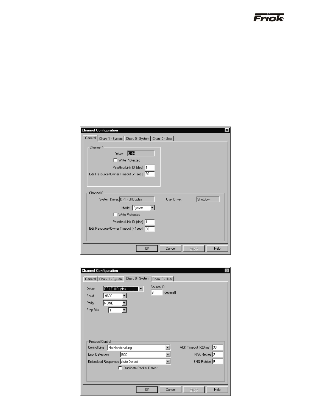
®
S90-010 CS (APR 08) FRICK
QUANTUM™ COMPRESSOR CONTROL PANEL
Page 26 COMMUNICATIONS SETUP
Read Message Setup Example
Instruction Entry for Message Block MG14:0:
Communication Command: SLC Typed Logical Read
PLC-5 Data Table Address: N9:3
Size in Elements: 20
Local/Remote: Local
Local Node Address: 004 (Quantum™ Panel’s ID)
Destination Data Table Address: N10:1
Port Number: 0
(Refer to the Allen-Bradley Programming Overview
Section for more information)
General Configuration
Allen-Bradley Programming Overview
This section contains programming examples for reading
data from, and writing data to the Frick
®
Quantum™
control panel from an Allen Bradley (AB) SLC500 or PLC5
processor. AB RSLogix500 programming software has
been used for the following examples, however, these
examples can also be used for the AB RSLogix5 software.
Channel Configuration
The following are representations of the channel
configuration screens from the AB RSLogix500
programming software for the SLC500. Enter values as
shown in order to establish communications via AB
Protocol.
System Configuration
Page 27

®
QUANTUM™ COMPRESSOR CONTROL PANEL S90-010 CS (APR 08)
FRICK
COMMUNICATIONS SETUP Page 27
Message Sequence Logic
Use the following logic to sequence read and write
message to the Quantum™ panel. This logic prevents
hang up due to lost communications or message errors.
Message Read Logic
Use the following logic to read data from the Quantum™
panel. To read more data or to read data from several
compressors, copy / paste these rungs as needed then
modify the control block and setup screen parameters
accordingly.
Page 28

®
S90-010 CS (APR 08) FRICK
QUANTUM™ COMPRESSOR CONTROL PANEL
Page 28 COMMUNICATIONS SETUP
Message Read Setup Screen
• This Controller: SLC500
• Data Table Address: Data file location in the
SLC500
• Size in Elements: # of data file to read
• Channel: Port location on the SLC processor
(Channel 0 is the RS-232 port)
The following setup screen is programmed to obtain 28
consecutive data files from the Quantum™ (ID#1) N10:1
register and place them into the SLC500’s N10:1 through
N10:28 register.
• Target Device: Quantum™ Panel
• Data Table Address: Data file location in the
Quantum™ controller.
• Local Node: Quantum™ ID# (Octal)
Page 29

®
QUANTUM™ COMPRESSOR CONTROL PANEL S90-010 CS (APR 08)
FRICK
COMMUNICATIONS SETUP Page 29
Message Write Logic
Use the following logic to write data from the Quantum™
panel. To write more data or to write data to several
compressors, copy / paste these rungs as needed then
modify the control block and setup screen parameters
accordingly.
Page 30

®
S90-010 CS (APR 08) FRICK
Page 30 COMMUNICATIONS SETUP
QUANTUM™ COMPRESSOR CONTROL PANEL
Message Write Setup Screen
The following setup screen is programmed to write the
• This Controller: SLC500
• Data Table Address: Data file location in the
SLC500
• Size in Elements: # of data file to read
• Channel: Port location on the SLC processor
(Channel 0 is the RS232 port)
compressor mode to the Quantum™ (ID#1) N55:3 data file
from the SLC500’s N55:3 data file.
• Target Device: Quantum™ Panel
• Data Table Address: Data file location in the
Quantum™ controller.
• Local Node: Quantum™ ID# (Octal)
Page 31

®
QUANTUM™ COMPRESSOR CONTROL PANEL S90-010 CS (APR 08)
FRICK
COMMUNICATIONS SETUP Page 31
MODBUS Protocol
Since Modbus protocol is a messaging structure, it is
independent of the underlying physical layer. It is
traditionally implemented using RS-232, RS-422, or RS485 communications hardware.
The Quantum™ controller is setup to communicate on
standard Modbus networks using ASCII (American
Standard Code for Information Interchange).
NOTE: With the Quantum™ Controller, ONLY Modbus
ASCII (7 or 8 data bits) is recognized, and all references to
Modbus protocol in this document will be as they relate to
ASCII. The mode and serial parameters must be the same
for all devices on a Modbus network, therefore, ensure
that your network is utilizing the Modbus ASCII protocol
before attempting to try to communicate to the Quantum™
portion of the network. Additionally, typical Modbus
protocols allow for network broadcasting, whereby a single
message can be sent to all devices simultaneously. This
Broadcasting is NOT allowed or supported by the
Quantum™ Controller.
The Quantum™ provides the capability to interface with
other devices that support serial data communications
using the Modbus ASCII protocol. This is a Master / Slave
multi-drop communication method whereby the
Quantum™ is setup to be a Modbus ASCII Slave. The
customer’s PLC (Programmable Logic Controller) or DCS
(Data Communications System, such as a desktop or
laptop computer) must be setup as a Modbus ASCII
Master. The Master initiates the reading and writing of
data (queries) to a Quantum™. The Quantum™ does not
generate its own data, it will only reply from a request by
the Master.
The Quantum™ ID number is used as the Modbus Slave
address. The Master uses Function Code 3 (Read Holding
Registers) to send a request to read data from the
Quantum™. The Master uses Function Code 6 (Load
Register) to request to change a setpoint or to send a
command such as starting the compressor. Up to fifty (50)
data elements can be read with one read request.
The most desired data (information on the Operating
Status screen) exists in a 50 (fifty) element data area. The
address references are numbered relative to the Frick
addresses in the Quantum™ Data Table (see MODBUS
Addressing Note in the Quantum™ Data Table section of
this manual for additional information). The Quantum™
only accepts one value with a Load Register request.
Changing a setpoint causes the Quantum™ to save the
new setpoint to nonvolatile memory. Be careful not to
continuously request a setpoint change. Keeping the
Quantum™ busy writing to memory will interfere with the
Quantum™ communicating to its I/O boards. A
communication failure to an I/O board will cause the
compressor to shutdown. For more detail and a list of the
data, reference the Quantum™ Data Table section of this
manual. For details about the actual protocol, reference
the Modicon website at http://www.modicon.com.
®
Port Configuration of The Master
7 or 8 Bits per Character (Data Bits)
Odd, Even or No Parity
1 or 2 Stop Bits
No Handshake
Data Packet
The Modbus protocol establishes the format for the
Master's query by creating a message (data packet) as
follows:
• Assign the device address (Quantum™ panel ID
#). The address field of a message frame
contains two characters (ASCII). Valid
Quantum™ device addresses are in the range of
01 – 99 decimal. A master addresses a
Quantum™ by placing the Quantum™ address in
the address field of the message. When the
Quantum™ sends its response, it places its own
address in this address field of the response to
let the Master know which Quantum™ is
responding.
• A function code defining the requested action
(Query):
• Function Code 3 - to read holding registers
(sends a request to read data from the
Quantum™).
- OR –
• Function Code 6 to load a register (to request to
change a setpoint or to send a command such as
starting the compressor).
• Any data to be sent (Response). The data field is
constructed using sets of two hexadecimal digits,
in the range of 00 to FF hexadecimal. These are
to be made from a pair of ASCII characters. The
data field of messages sent from a Master to the
Quantum™ devices contains additional
information which the Quantum™ must use to
take the action defined by the function code. This
can include items like discrete and register
addresses, the quantity of items to be handled,
and the count of actual data bytes in the field. If
no error occurs, the data field of a response from
a Quantum™ to a Master contains the data
requested. If an error occurs, the field contains
an exception code that the Master application
can use to determine the next action to be taken.
• An error-checking field.
Page 32

®
S90-010 CS (APR 08) FRICK
QUANTUM™ COMPRESSOR CONTROL PANEL
Page 32 COMMUNICATIONS SETUP
The Query
The function code in the query tells the addressed
Quantum™ what kind of action to perform. The data bytes
contain any additional information that the Quantum™ will
need to perform the function. For example, function code
03 will query the Quantum™ to read holding registers and
respond with their contents. The data field must contain
the information telling the Quantum™ which register to
start at and how many registers to read. The error check
field provides a method for the Quantum™ to validate the
integrity of the message contents.
The Response
If the Quantum™ makes a normal response, the function
code in the response is an echo of the function code in the
query. The data bytes contain the data collected by the
Quantum™, such as register values or status. If an error
occurs, the function code is modified to indicate that the
response is an error response, and the data bytes contain
a code that describes the error. The error check field
allows the master to confirm that the message contents
are valid.
Data Field
The data field is constructed using sets of two
hexadecimal digits, in the range of 00 to FF hexadecimal.
These can be made from a pair of ASCII characters.
The data field of messages sent from a master to the
Quantum™ devices contains additional information which
the Quantum™ must use to take the action defined by the
function code. This can include items like discrete and
register addresses, the quantity of items to be handled,
and the count of actual data bytes in the field.
For example, if the master requests a Quantum™ to read
a group of holding registers (function code 03), the data
field specifies the starting register and how many registers
are to be read.
If no error occurs, the data field of a response from a
Quantum™ to a Master contains the data requested. If an
error occurs, the field contains an exception code that the
Master application can use to determine the next action to
be taken.
Error Checking
When data is transmitted to and from the Quantum™
Controller, each message has an Error Checking value
appended to the end of the message. Because the
Quantum™ utilizes Modbus ASCII protocol, Longitudinal
Redundancy Check, or LRC, is used as the method for
verifying that the message sent from the transmitting
device, was properly received by the receiving device.
The Longitudinal Redundancy Check (LRC) field is one
byte, containing an eight-bit binary value. The LRC value
is calculated by the transmitting device, by adding together
successive eight-bit bytes of the message, discarding any
carries, and then two's complementing the result. It is
performed on the ASCII message field contents excluding
the colon character that begins the message, and
excluding the CRLF pair at the end of the message. The
LRC is then appended to the message as the last field
preceding the CRLF (Carriage – Line Feed) characters.
Each new addition of a character that would result in a
value higher than 255 decimal simply rolls over the field's
value through zero. Because there is no ninth bit, the carry
is discarded automatically.
The receiving device recalculates an LRC during receipt of
the message, and compares the calculated value to the
actual value it received in the LRC field. If the two values
are not equal, an error results.
ASCII Framing
In ASCII mode, messages start with a colon ( : ) character
(3A hex), and end with a carriage return-line feed (CRLF)
pair (0D and 0A hex).
The allowable characters transmitted for all other fields are
hexadecimal 0 - 9, A - F.
All Quantum™ panels connected to the network monitor
the network bus continuously for the colon character.
When one is received, each Quantum™ decodes the next
field (the address field) to find out if it is the addressed
device.
A Modbus message is placed by the transmitting device
into a frame that has a known beginning and ending point.
This allows receiving devices to begin at the start of the
message, read the address portion and determine which
device is addressed, and to know when the message is
completed. Partial messages can be detected and errors
can be set as a result.
A typical message frame as sent by the Master is shown
below.
START ADDRESS FUNCTION DATA LRC CHECK END
: 01 03 00870001 74 CRLF
1 CHAR 2 CHAR 2 CHAR 8 CHAR 2 CHAR 2 CHAR
Where
: = Start of Message
01 = Quantum™ ID
03 = Read Function
00 = H.O. address (hex)
87 = L.O. address (hex)
00 = H.O. # of Data Registers
01 = L.O. # of Data Registers
74 = Error Correction Code
CRLF = Carriage Return – Line Feed
Page 33

®
QUANTUM™ COMPRESSOR CONTROL PANEL S90-010 CS (APR 08)
FRICK
COMMUNICATIONS SETUP Page 33
Query (Read) Example:
To demonstrate how an address within the Quantum™
may be read, the following test can be performed using
Windows HyperTerminal:
As an example, a Modbus command will be created, and
sent to obtain the actual Discharge Pressure value of a
compressor. Using the address tables found later in this
manual, locate the address for Discharge Pressure. In this
case, it would be Frick
is the only address we are interested in obtaining the
value of, send the following message:
Where:
Start of Message
Quantum™ ID #
Read Function
H.O. address (hex)
L.O. address (hex)
H.O. # of Data Registers
L.O. # of Data Registers
Error Correction Code
Carriage Return – Line Feed
Look at this message on a more basic level, to understand
how the address that we are requesting is arrived at. We
want to know the actual value of the Discharge Pressure,
®
Frick
Address 135 (decimal).
The first part of the message will be a Colon (:). This
represents a heads up alert that data is coming down the
line.
Where:
Start of Message
Quantum™ ID #
Read Function
H.O. address (hex)
L.O. address (hex)
H.O. # of Data Registers
L.O. # of Data Registers
Error Correction Code
Carriage Return – Line Feed
®
Address 135 (decimal). Since this
: 01 03 00 87 00 01 74 CRLF
}
: 01 03 00 87 00 01 74 CRLF
Any time that a message is sent, all of the Quantum™
panels that are on the Modbus network will become active,
communications wise, once the Colon appears. Next, all
panels will look at the first byte following the Colon ( : ). If
this byte equals the Panel ID # of the particular
Quantum™ being queried, it will immediately finish
reading the remainder of the message. If the byte does not
equal its ID #, the message will be ignored.
Where:
Start of Message
Quantum™ ID #
Read Function
H.O. address (hex)
L.O. address (hex)
H.O. # of Data Registers
L.O. # of Data Registers
Error Correction Code
Carriage Return – Line Feed
In this particular example, we are strictly looking to request
to view a data value, so we will be performing a read
function (03):
Where:
Start of Message
Quantum™ ID #
Read Function
H.O. address (hex)
L.O. address (hex)
H.O. # of Data Registers
L.O. # of Data Registers
Error Correction Code
Carriage Return – Line Feed
135 decimal equals 87 hex. Looking at our example, we
see that we need a H.O. (High Order) address and a L.O.
(Low Order) address. Since all data sent and received is in
ASCII Hex Byte format, we need to look at 87 Hex as the
Low Order portion of the address. The High Order portion
is 00. Now our decimal 135 is formatted as 0087 Hex.
}
: 01 03 00 87 00 01 74 CRLF
}
: 01 03 00 87 00 01 74 CRLF
: 01 03 00 87 00 01 74 CRLF
Where:
Start of Message
Quantum™ ID #
Read Function
H.O. address (hex)
L.O. address (hex)
H.O. # of Data Registers
L.O. # of Data Registers
Error Correction Code
Carriage Return – Line Feed
}
Page 34

®
}
S90-010 CS (APR 08) FRICK
Page 34 COMMUNICATIONS SETUP
QUANTUM™ COMPRESSOR CONTROL PANEL
Since we are only looking for this one address, and no
other, we can say that we are only looking for one Data
Address. Our Data Address part of the data packet is also
looking for a High and a Low Order value. Fortunately, the
number one (1) is the same in decimal as it is in Hex,
therefore, the Low Order Address is 01 (hex). The High
Order Address is 00 (hex), so our decimal 1 is formatted
as 0001 (hex).
Where:
Start of Message
Quantum™ ID #
Read Function
H.O. address (hex)
L.O. address (hex)
H.O. # of Data Registers
L.O. # of Data Registers
Error Correction Code
Carriage Return – Line Feed
In order to ensure that the Quantum™ in question
receives the data request accurately, we must append an
Error Check byte to the end of the message. This is
accomplished by adding each of the byte pairs (hex) that
we have generated thus far:
01 + 03 + 00 + 87 + 00 + 01 = 8C hex
Next, subtract 8C (hex) from 100 (hex):
Where:
Start of Message
Quantum™ ID #
Read Function
H.O. address (hex)
L.O. address (hex)
H.O. # of Data Registers
L.O. # of Data Registers
Error Correction Code
Carriage Return – Line Feed
After the entire data packet has been created, simply
press the [Enter] key, a Line Feed will automatically be
sent also.
Where:
Start of Message
Quantum™ ID #
Read Function
H.O. address (hex)
L.O. address (hex)
H.O. # of Data Registers
L.O. # of Data Registers
Error Correction Code
Carriage Return – Line Feed
: 01 03 00 87 00 01 74 CRLF
100 (hex) - 8C (hex) = 74 (hex)
: 01 03 00 87 00 01 74 CRLF
: 01 03 00 87 00 01 74 CRLF
}
}
Write Example:
To demonstrate how an address within the Quantum™
may be written to, the following test can be performed
using Windows HyperTerminal:
As an example, a Modbus command will be created, and
sent to set the Quantum™ to set the Suction Pressure
Control Point 1 to 100.0 PSIA. First, be aware that data
sent to and received by the Quantum™ has one decimal
place assumed. This means that to send the value of
100.0, you actually need to send 1000. Using the address
tables found later in this manual, locate the address for the
Suction Pressure Control Point 1. In this case, it would be
®
Frick
Address 277 (decimal). Since this is the only
address we are interested in writing to, send the following
message:
Where:
Start of Message
Quantum™ ID #
Write Function
H.O. address (hex)
L.O. address (hex)
H.O. # of Data Value
L.O. # of Data Value
Error Correction Code
Carriage Return – Line Feed
Look at this message on a more basic level, to understand
how the address that we are writing to is arrived at. We
want to send the value of 1000 (100.0) to the Suction
Pressure Control Point 1, Frick
The first part of the message will be a Colon (:). This
represents a heads up alert that data is coming down the
line.
Where:
Start of Message
Quantum™ ID #
Write Function
H.O. address (hex)
L.O. address (hex)
H.O. # of Data Value
L.O. # of Data Value
Error Correction Code
Carriage Return – Line Feed
Any time that a message is sent, all of the Quantum™
panels that are on the Modbus network will become active,
communications wise, once the Colon appears. Next, all
panels will look at the first byte following the Colon (:). If
this byte equals the Panel ID # of the particular
Quantum™ being queried, it will immediately finish
reading the remainder of the message. If the byte does not
equal its ID #, the message will be ignored.
: 01 06 01 15 03 E8 F8 CRLF
®
Address 277 (decimal).
}
: 01 06 01 15 03 E8 F8 CRLF
Page 35

®
}
QUANTUM™ COMPRESSOR CONTROL PANEL S90-010 CS (APR 08)
FRICK
COMMUNICATIONS SETUP Page 35
In this particular example, we are strictly looking to write a
data value, so we will be performing a write function (06):
Where:
Start of Message
Quantum™ ID #
Write Function
H.O. address (hex)
L.O. address (hex)
H.O. # of Data Value
L.O. # of Data Value
Error Correction Code
Carriage Return – Line Feed
277 decimal equals 115 hex. Looking at our example, we
see that we need a H.O. (High Order) address and a L.O.
(Low Order) address. Since all data sent and received is in
ASCII Hex Byte format, we need to look at 15 Hex as the
Low Order portion of the address. The High Order portion
is 01. Now our decimal 277 is formatted as 0115 Hex.
Where:
Start of Message
Quantum™ ID #
Write Function
H.O. address (hex)
L.O. address (hex)
H.O. # of Data Value
L.O. # of Data Value
Error Correction Code
Carriage Return – Line Feed
The value that we wish to send is 100.0 (1000). Our Data
Value part of the data packet is looking for a High and a
Low Order value. The number 1000 (dec) must be
converted to hexadecimal. This conversion results in 03E8
(hex). Separating 03E8 into two bytes results in the Low
Order Value of E8 (hex) and the High Order Value of 03
(hex):
Where:
Start of Message
Quantum™ ID #
Write Function
H.O. address (hex)
L.O. address (hex)
H.O. # of Data Value
L.O. # of Data Value
Error Correction Code
Carriage Return – Line Feed
: 01 06 01 15 03 E8 F8 CRLF
: 01 06 01 15 03 E8 F8 CRLF
: 01 06 01 15 03 E8 F8 CRLF
}
}
}
In order to ensure that the Quantum™ in question
receives the data request accurately, we must append an
Error Check byte to the end of the message. This is
accomplished by adding each of the byte pairs (hex) that
we have generated thus far:
01 + 06 + 01 + 15 + 03 + E8 = 108 hex
Normally, we would subtract 108 (hex) from 100 (hex), as
in the previous read example. However, in this case we
see that 108 hex is greater than 100 hex. Since the math
in this particular example would yield a negative number
(FFFFFFF8), we need to modify the value of 108 in order
to provide a positive result. This is accomplished quite
simply by dropping the most left hand digit (108 becomes
08), and then subtracting 8 hex from 100 hex:
100 (hex) - 08 (hex) = F8 (hex)
Where:
Start of Message
Quantum™ ID #
Write Function
H.O. address (hex)
L.O. address (hex)
H.O. # of Data Value
L.O. # of Data Value
Error Correction Code
Carriage Return – Line Feed
After the entire data packet has been created, simply
press the [Enter] key, a Line Feed will automatically be
sent also.
Where:
Start of Message
Quantum™ ID #
Write Function
H.O. address (hex)
L.O. address (hex)
H.O. # of Data Value
L.O. # of Data Value
Error Correction Code
Carriage Return – Line Feed
: 01 06 01 15 03 E8 F8 CRLF
: 01 06 01 15 03 E8 F8 CRLF
}
Page 36

®
S90-010 CS (APR 08) FRICK
QUANTUM™ COMPRESSOR CONTROL PANEL
Page 36 COMMUNICATIONS SETUP
Response Example:
If the packet was properly received by the Quantum™,
you should see an immediate response in HyperTerminal.
In the Query Response (read function) example used
earlier, a response of :01030205D025 (hex) was received.
Once again, the first part of the message will be a Colon
(:). This represents a heads up alert that data is coming
down the line, but since the data is coming from the
Quantum™ to the Master this time, the Master will accept
it.
Where:
Start of Message
Quantum™ ID #
Read Function
Number of Bytes Returned
Data
Error Correction Code
After having received the Colon (:), the Master will look at
the two bytes that follows it, so that it may determine from
which Quantum™ the message is coming from.
Where:
Start of Message
Quantum™ ID #
Read Function
Number of Bytes Returned
Data
Error Correction Code
Now that the Master knows which panel is responding, it
needs to known which function the panel is responding to.
In this case, it sees that it is a read function, and the
Quantum™ is merely returning a value that was previously
requested.
Where:
Start of Message
Quantum™ ID #
Read Function
Number of Bytes Returned
Data
Error Correction Code
}
: 01 03 02 05 D0 25
}
: 01 03 02 05 D0 25
{
: 01 03 02 05 D0 25
The next byte tells the Master how many bytes of
information are being returned as a response. In this case,
there are two (2) bytes of valid data.
Where:
Start of Message
Quantum™ ID #
Read Function
Number of Bytes Returned
Data
Error Correction Code
: 01 03 02 05 D0 25
{
The next two bytes (in this case) are the actual data in
response to our original request.
Where:
Start of Message
Quantum™ ID #
Read Function
Number of Bytes Returned
Data
Error Correction Code
: 01 03 02 05 D0 25
We need to know what this value means. To break it
down, we must convert the pair of bytes from Hex to
Decimal:
05DO (hex) = 1488 (decimal)
Data to and from the Quantum™ are integer values with
one decimal field assumed unless shown otherwise or the
command is sent to select two decimal fields.
From the previous paragraph, we can assume that there is
one decimal place to be applied to the data value that was
returned. Therefore:
1488 (decimal) = 148.8 (decimal)
All temperatures are in degrees C and all pressures are in
PSIA unless the command is sent to select the units of the
panel. Therefore:
148.8 (decimal) = 148.8 PSIA
Page 37

®
QUANTUM™ COMPRESSOR CONTROL PANEL S90-010 CS (APR 08)
FRICK
COMMUNICATIONS SETUP Page 37
MODBUS NOTES:
This has been an example of how the Quantum™
Controller uses the Modbus Protocol. It is hoped that the
information provided here will assist the end user in writing
applications that will allow the Quantum™ to be
implemented into networks that the customer may already
have in use.
This information is subject to change at any time, and is
provided as a reference only. Not all areas of the Modbus
Protocol can be handled in this document. Some
additional information regarding Modbus Protocol that the
end user should be aware of:
• There are many versions of Modbus Protocol that
is available, and an application that works
properly on one system, may not function
identically on another.
• Some versions of Modbus Protocol may require
the user to increment any referenced addresses
by 1 (one). For instance, if you wanted to look at
®
Frick
Address 135, you may need to actually
look at address 136. The Quantum™ addressing
begins at 0 (zero), whereas some Modbus
Protocols begin at 1 (one), therefore, you may
need to compensate.
• DO use Modbus ASCII. DO NOT use Modbus
RTU.
• 7 or 8 Data bits may be used.
• 1 or 2 Stop bits may be used.
• Parity can be set to None, Odd or Even
• Follow the Frick
®
specifications for data
communications requirements.
NOTE: Be careful not to continuously request a
setpoint change. It is to be expected that
communications may slow down during the process
of writing setpoints or clearing alarms. Both of these
processes involve writing to either EEPROM or Flash
Memory and does take some time. If communication
requests are being sent faster than once every couple
of seconds, there will be temporary slowdowns during
these processes.
Page 38

®
S90-010 CS (APR 08) FRICK
QUANTUM™ COMPRESSOR CONTROL PANEL
Page 38 COMMUNICATIONS SETUP
YORK ISN DATA ACCESS
ISN Revision 7
The Quantum™ panels Com-2 serial port is connected to
a ISN’s RS-485 serial port that is configured for York Talk
communications. Wire the ISN’s –RX / -TX to the
Quantum™ P12 pin 1 (-RX / -TX) and wire the ISN’s +RX /
+TX to the Quantum™ P12 pin 2 (+RX / +TX). Check that
the ISN communication protocol has been selected from
the Panel Setup – Change Communications screen and
that the baud rate of Com-2 and the panel ID number
coincide with the setup of the ISN device. The Quantum™
ID number is used for the ISN Node number.
The data exchanged with the ISN is found on pages (P) in
feature (F) 54 of the ISN. All temperatures are in degree C
and all pressures are in PSIA. A mode such as Slide Valve
mode is sent as an integer value that represents the mode
it is in. For example, a zero (0) is sent if it is in manual, or
a 1 is sent if it is in automatic, or a 2 is sent if it is in
remote. When changing a setpoint, the setpoint range is
checked to see if the received value is an allowed setting.
If it is not allowed, the setting is not changed.
If the compressor is to be remotely controlled and the
settings being sent from the ISN are not wanted to be
used for control, then two digital bytes must be set to a
one (1) to tell the Quantum to ignore the control settings
being sent to it from the ISN. Sending a one (1) in the
Start/Stop Enable digital byte from the ISN will signal the
Quantum to ignore the Start/Stop digital value received
from the ISN. Sending a one (1) in the Change Setpoints
Enable digital byte from the ISN will signal the Quantum to
ignore the setpoint values received from the ISN.
If the compressor is to be remotely controlled from the ISN
settings, then the compressor must be in remote to accept
the start and stop commands that are sent through serial
communication and the Start/Stop Enable received from
the ISN must equal zero (0). To change a setpoint the
Following is a listing of the Quantum™ data that is sent to the ISN and the resulting ISN address:
ISN Address Description of Data
P11-A01 Suction Temperature
P12-A02 Discharge Temperature
P13-A03 Oil Temperature
P14-A04 Oil Separator Temperature
P15-A05 Leaving Process Temperature
P16-A06 Oil Pressure
P17-A07 Filter Differential Pressure
P18-A08 Discharge Pressure
P19-A09 Suction Pressure
P20-A10 Balance Piston Pressure
P21-A11 System Discharge Pressure
P22-A12 Calculated Slide Valve Position
P23-A13 Slide Stop Position
P24-A14 Motor Current Amps
P25-A15 Motor Full Load Amps %
P26-A16 Entering Process Temperature
P27-A17 User-Defined Pressure/Temperature #1 Monitor only
P28-A18 High Motor Amps Force Unload Setpoint
P29-A19 High Motor Amps Stop Load Setpoint
P30-A20 Anti Recycle Delay Setpoint
P31-A21 Slide Valve Minimum Start Setpoint
Change Setpoint Enable received from the ISN must equal
zero (0)
Note: The Quantum can still communicate to an ISN
panel that has revision 6 software if the baud rate is set for
1200, 2400, or 4800.
Quantum™ Receiving from ISN:
4 byte Analogs A1-A4
4 x 1 byte Digitals D1-D4
P03
Analog 1
P04
Analog 2
P05
Analog 3
P06
Analog 4
P07
Digital 1
P08
Digital 2
P09
Digital 3
P10
Digital 4
Capacity.Sp
Amps.Force_Unl.Sp
Amps.Stop_Load.Sp
Spare
Start Remote Start/Stop
Start/Stop Enable
Change Setpoints
Enable
Spare
Quantum™ Sending to ISN:
25 x 4 byte Analogs A01-A25
20 x 1 byte Digitals D01-D20
10 x 1 byte Codes (OC) OP CODE 01 - OP CODE 10
14 x 4 byte Analogs A26-A39
5 x 1 byte Digitals D21-D25
Total = 191 data bytes
Capacity setpoint for
the current capacity
Control
High Motor Amps
Force Unload
setpoint
High Motor Amps
Stop Load setpoint
0 = Enabled
1 = Disabled
0 = Enabled
1 = Disabled
Page 39

®
QUANTUM™ COMPRESSOR CONTROL PANEL S90-010 CS (APR 08)
FRICK
COMMUNICATIONS SETUP Page 39
ISN Address Description of Data Module Type Value Code
P32-A22 Current mode Autocycle Start
P33-A23 Current mode Autocycle Stop
P34-A24 Current mode Autocycle Start Delay Time
P35-A25 Current mode Autocycle Stop Delay Time
P36-D01 Compressor Start Output 0 = Off, 1 = On
P37-D02 Compressor Auxiliary Input 0 = Off, 1 = On
P38-D03 Oil Pump #1 Start/Run Output 0 = Off, 1 = On
P39-D04 Oil Pump #1 Auxiliary Input 0 = Off, 1 = On
P40-D05 Slide Valve Load Output 0 = Off, 1 = On
P41-D06 Slide Valve Unload Output 0 = Off, 1 = On
P42-D07 Slide Stop Increase Output 0 = Off, 1 = On
P43-D08 Slide Stop Decrease Output 0 = Off, 1 = On
P44-D09 Liquid Injection Output 0 = Off, 1 = On
P45-D10 Hi-Vi Liquid Injection Output 0 = Off, 1 = On
P46-D11 Economizer Output 0 = Off, 1 = On
P47-D12 Balance Piston Output 0 = Off, 1 = On
P48-D13 Oil Level Input 0 = Off, 1 = On
P49-D14 High Liquid Level from System Input 0 = Off, 1 = On
P50-D15 Enclosure Heater Output 0 = Off, 1 = On
P51-D16 Hot Gas Bypass Output 0 = Off, 1 = On
P52-D17 Aux. #1 Input 0 = Off, 1 = On
P53-D18 Aux. #2 Input 0 = Off, 1 = On
P54:D19 Process Mode Select Input 0 = 1st Mode, 1 = 2nd Mode
P55:D20 Capacity Control Setpoint #2 Input 0 = Mode 1, 1 = Mode 2
P80:D21 Oil Heater Output 0 = Off, 1 = On
P81:D22 Alarm Output 0 = None, 1 = Alarm
P82:D23 Shutdown Output 0 = Shutdown, 1 = None
P83:D24 Power Assist Output 0 = Off, 1 = On
P84:D25 SPARE
ISN Address Description of Data Value Code
P56-OC01 Recycle delay time in minutes
P57-OC02 Compressor Mode 0 = Manual
1 = Automatic cycling
2 = Remote Start
P58-OC03 Slide Valve Mode 0 = Manual
1 = Automatic
2 = Remote
3 = Remote Control Setpoint
P59-OC04 Compressor Running Status 0 = Off, 1 = Running, 2 = Starting
P60-OC05 Process Control Mode 0 = Suction Pressure Control Mode 1
1 = Suction Pressure Control Mode 2
2 = Temperature Control Mode 1
3 = Temperature Control Mode 2
4 = Discharge Pressure Control Mode 1
5 = Discharge Pressure Control Mode 2
6 = User Selectable Control Mode 1
7 = User Selectable Control Mode 2
P61-OC06 Capacity Control Mode 0 = Keypad
1 = Autocycle
2 = Remote
3 = Remote I/O
4 = Remote Communications
5 = Schedule
Page 40

®
)
)
S90-010 CS (APR 08) FRICK
QUANTUM™ COMPRESSOR CONTROL PANEL
Page 40 COMMUNICATIONS SETUP
ISN Address Description of Data Value Code
P62-OC07
Stop/Force Unload Status
0 = Not stopping or forcing unload
1 = Stop Load - High Motor Amps
2 = Stop Load - High Discharge Pressure
3 = Stop Load - High Discharge Temperature
4 = Stop Load - Low Suction Pressure
5 = Stop Load - High Suction Pressure
6 = Stop Load - Low Process Temperature
7 = Force Unload - High Motor Amps
8 = Force Unload - High Discharge Pressure
9 = Force Unload - High Discharge Temperature
10 = Force Unload - Low Suction Pressure
11 = Force Unload - High Suction Pressure
12 = Force Unload - Low Process Temperature
13 = Stop Load - Low Oil Flow
14 = Force Unload - Low Oil Flow
15 = Force Unload - VI OverRide
16 = At Maximum Load
17 = Stop Load - Separator Velocity
18 = Force Unload - Separator Velocity
19 = Force Unload - Stopping
20 = Stop Load - Low RPM
21 = Force Unload - Low RPM
22 = Stop Load - High Manifold Pressure
23 = Force Unload - High Manifold Pressure
24 = Warm-up Load Inhibit
25 = Slide Valve Pulldown
P63-OC08 Alarm Code (1)
P64-OC09 Alarm Code (2)
P65-OC10 Alarm Code (3)
ISN Address Description of Data
P66-A26 Current Capacity Control setpoint
P67-A27 Current Upper proportional band
P68-A28 Current Lower proportional band
P69-A29 Current Upper dead band
P70-A30 Current Lower dead band
P71-A31 Process Temperature mode Stop Load (Only process Temperature
P72-A32 Process Temperature mode Force Unload (Only process Temperature
P73-A33 Process Temperature mode low Temperature alarm (Only process Temperature )
P74-A34 Process Temperature mode low Temperature shutdown (Only process Temperature )
P75-A35 Current mode Low Suction Press. Stop Load
P76-A36 Current mode Low Suction Press. Force Unload
P77-A37 Current mode Low Suction Press. Alarm
P78-A38 Current mode Low Suction Press. Shutdown
P79-A39 SPARE
Page 41

®
QUANTUM™ COMPRESSOR CONTROL PANEL S90-010 CS (APR 08)
FRICK
COMMUNICATIONS SETUP Page 41
HYPERTERMINAL
HyperTerminal is a terminal emulation program which
resides in the MicroSoft Windows environment, and as
such, will normally be found on any computer that is
running Microsoft Windows. HyperTerminal provides a
method by which the end user may verify conclusively that
their Quantum™ controller is functioning properly, and as
designed, with respect to external communications to
remote devices.
Many times, the Quantum™ controller will be installed into
an environment whereby the end user wishes to
communicate to it, either through a PLC (Programmable
Logic Controller), a desktop computer for the purpose of
monitoring/controlling plant operations through HMI
(Human Machine Interface), or any number of other
communications applications.
The purpose of this desired communications typically
involves viewing and changing setpoints, starting and
stopping a compressor, viewing alarm and shutdown
information, and viewing current operating conditions.
When first connecting a Quantum™ panel to a
communications network, it would be highly desirable to
determine that all necessary parameters (jumper settings,
panel setup, and cabling) are properly met so that
communications may be established quickly with the
Quantum™, so that time is not lost in trying to
troubleshoot a potentially simple problem.
A modem or direct connection from a Comm port of a
computer running Microsoft Windows can be used to
connect to Com-2 of the Quantum™.
Setting up Hyperterminal
• You will need to locate either a lap top or desktop
computer, that has Hyperterminal installed.
• Turn on the power for the lap top.
• After the laptop has fully booted, locate the
Hyperterminal program. (Hyperterminal is usually
found in the Accessories folder). If Hyperterminal
can't be found there, try using the Find File
command, and search the entire hard drive.
• Be aware that the screens that are actually shown
on the test computer may or may not appear
exactly as shown here. Various versions of
Windows can affect the appearance, as well as
whether or not the screen has been maximized,
or if it has been scaled to a smaller size.
Regardless of how the screen work appears, the
function of the screen work is what is important,
and that function is not affected by the way the
screen looks.
• Once Hyperterminal has been located, execute it.
A dialog box will appear. You will be prompted to
enter a name for the New Connection. Type in
whatever name you would like to use, Frick
used in this example. This name will also create
a file once you are finished, saving all of the
setup parameters for future use. It is
recommended that a name be chosen to reflect
the type of Protocol that you will be using as you
may wish to setup for various protocols. Once
you have entered a name, click [OK].
®
was
Page 42

®
S90-010 CS (APR 08) FRICK
QUANTUM™ COMPRESSOR CONTROL PANEL
Page 42 COMMUNICATIONS SETUP
A new dialog box will be shown asking to select a Com
port (choose the Com port that your communications cable
The Com-1 properties dialog box will now appear. The
parameters in this box must match the requirements of the
protocol that you are wishing to use. The one box that
normally would need to be changed from one protocol to
the next is the Data Bits box. For Modbus, you would want
to use 7 data bits, for Frick
®
and Quantum™ protocols, use
8 data bits.
NOTE: Allen-Bradley protocol cannot be tested using
Hyperterminal.
For the purpose of this document, Frick
®
# protocol will be
used. Refer to the Modbus section of this manual for
information on Modbus.
is attached to, this will normally be Com-1). The phone
number box should be blank. Click on [OK].
Set the five boxes as follows, then click [OK].
• Bits per second: 9600 (must match the
Quantum™)
• Data bits: 8
• Parity: None
• Stop Bits: 1
• Flow Control: None
Page 43

®
QUANTUM™ COMPRESSOR CONTROL PANEL S90-010 CS (APR 08)
FRICK
COMMUNICATIONS SETUP Page 43
The following screen will appear. This is the screen
whereby all communications (out of the computer, and into
it) will be shown. When valid data is typed in here, then
sent, the connected device recognizes and responds to
A pull down menu will appear. From this menu, locate and
click on [Properties]. You will once again see the
that data, and a response will be shown below the sent
data. Click on [File].
following screen. This time, click on the [Settings] tab.
Page 44

®
S90-010 CS (APR 08) FRICK
QUANTUM™ COMPRESSOR CONTROL PANEL
Page 44 COMMUNICATIONS SETUP
The computer will need to be set up to match the
documentation as presented here, for everything to look
On the ASCII Setup screen, for best results, check the
boxes according to the following chart:
For Modbus:
• Send line ends with line feeds
• Echo typed characters locally
• Append line feeds to incoming line ends
• Wrap lines that exceed terminal width
and work as shown later. To do this, click on the [ASCII
Setup…] button.
For Frick
®
protocols (# and $):
• Echo typed characters locally
• Append line feeds to incoming line ends
• Wrap lines that exceed terminal width
Leave everything else on this dialog box unchanged, then
click on [OK].
Page 45

®
QUANTUM™ COMPRESSOR CONTROL PANEL S90-010 CS (APR 08)
FRICK
COMMUNICATIONS SETUP Page 45
The Properties screen will once again be shown. Click on
the [OK] button to proceed.
You will now be back to the main Hyperterminal
communications screen. This screen will be blank. All
communications, both from the computer, and to the
computer (from the Quantum™), will appear on this
screen. Proceed to the Testing Communications section.
Page 46

®
S90-010 CS (APR 08) FRICK
QUANTUM™ COMPRESSOR CONTROL PANEL
Page 46 COMMUNICATIONS SETUP
Testing Communications
Set the keyboard for CAPS (so that all capital letters will
If the communications is working properly, there should be
an immediate response from the first Quantum™. The
response should look something (but not necessarily
exactly) like #01I000AOMN609.
Go to the first Quantum™ in line, and check the Show
Comms screen that was described earlier. You should
see your message (and the Quantum™ reply) displayed
there.
If this portion of the test has passed, you can try to
communicate to the next (or any Quantum™, by changing
the value that you type into the HyperTerminal screen as
follows:
Instead of [#01], replace the 01 portion with the ID
that you would like to access. For instance, if you
wanted to talk to a fourth Quantum™ (ID 4), type in
[#04]. This should return a message from that
Quantum™.
This has been just a brief description of how to check your
communications and verify that it is working. Greater detail
can be found by consulting tables for each of the protocols
in this manual.
General Notes:
Ensure that the Quantum™ is set for the correct ID
number, BAUD rate and type of communications protocol
that is to be used. This setup can be found by pressing the
[Menu] key on the keypad, then pressing the [Panel
Setup] key that will appear at the right side of the display.
When the panel setup appears, look at the information at
the CHANGE COMMS line of the screen. This info must
match the communications that you are trying to establish
at the other end.
be typed). Type in the following command: #01I, then
press [ENTER]. (This command will request the
Quantum™ with ID 01 to send a packet of Information.)
There are two red LED’s associated with the Com-2 port
on the Quantum™ (TX2 & RX2). Ensure that neither of
these LED’s are on continuously. If one or the other (or
both) are on constantly, disconnect the Com cable. If the
status of the LED’s does not change, check the wiring
connections to the communications port. Ensure that the
wiring is not backwards. If the wiring is correct, power the
Quantum™ down, then back up. If either or both of the
LED’s is still on, a bad driver chip may be suspected on
the Quantum™, and the board should be replaced.
Once everything has been inspected (cables, jumpers,
and setup), try to develop communications from the
master. You should see the LED’s on the Com-2 port
flickering as the Quantum™ talks to the master. If nothing
happens, it would be best to consult the HyperTerminal
section of this memo for more detailed troubleshooting.
If you do see the LED’s flickering, but data at the master
device does not look correct, you can verify what is being
sent and received at the Quantum™ by:
Pressing the [Menu] key on the keypad, then when the
Main Menu screen appears, find and press the [MORE…]
button.
A second Main Menu screen will appear. Find and press
the [Service Screen] key
Page 47

®
QUANTUM™ COMPRESSOR CONTROL PANEL S90-010 CS (APR 08)
FRICK
COMMUNICATIONS SETUP Page 47
The Service Screen will appear. Press the [Show
Comms] key at the top right of the screen to view the
You will now be viewing all of the communications
information that Com-2 is receiving and transmitting. This
screen will require you to update it manually be pressing
the [Show Comms] key periodically.
This screen will display all data that is coming through the
Com ports. At the left of each line, you should see whether
the data is IN or OUT (Receive or Send). Followed by
COMM X (which com port of the Quantum™ is doing the
talking). And lastly, the actual data (in Hexadecimal
format).
Ensure that this Hex data matched the data at the master.
Refer to the Conversion Chart For Decimal / Hexadecimal
/ ASCII in this manual for assistance in decoding the
communications data.
If no data appears, or if the data does not match the
specific protocol requirements that you are using, then one
of the following things can be the problem:
• Quantum™ Panel Setup is wrong. Access the
Panel Setup screen and verify that the
Quantum™ ID is set to the same value that you
are trying to access. Also, check that the baud
rate matches that of the setup in the properties
section of the Hyperterminal example.
• Quantum™ jumpers. Verify the position of the
jumpers by comparing them with the section
communications information.
entitled Quantum™ 3 Communications Jumpers
for the Quantum™ 3, or entitled Quantum™ 4
Communications Jumpers, for the Quantum™ 4.
• Incorrect data is being entered in Hyperterminal.
Ensure that the data that you have entered,
exactly matches the example. Use capital letters.
• Go back through the Setting up Hyperterminal
section, and ensure that it has been followed
exactly. Repeat the process if necessary.
• If you are using a converter card (to convert the
RS-232 signal from the computer to RS-422 or
RS-485), then either verify that the converter card
is working properly with a different piece of
known functioning equipment, or eliminate it
completely by tying into the Quantum™ directly
through RS-232.
• The Communications port on the computer is
bad. Try to verify this by communicating to a
different piece of known good equipment.
• The Communications port on the Quantum™ is
bad.
Page 48

®
S90-010 CS (APR 08) FRICK
QUANTUM™ COMPRESSOR CONTROL PANEL
Page 48 COMMUNICATIONS SETUP
QUANTUM™ DATA TABLE
Allen-Bradley and Modbus Data Access
Data passed to and from the Quantum™ are integer
values with one decimal field assumed unless shown
otherwise or the command is sent to select two decimal
fields. For example, if the data’s value is 25.5 then the
value 255 is sent. All temperatures are in degree C and all
pressures are in PSIA unless the command is sent to
select the units of the panel. A mode such as Slide Valve
mode is sent as an integer value that represents the mode
it is in. For example, a 0 is sent if it is in manual, or a 10 is
sent if it is in automatic, or a 20 is sent if it is in remote.
The value zero (0) is used to represent an OFF status and
a DISABLED option. The value one (1), which is received
as a 10, is used to represent an ON status and an
ENABLED option. Only data values that are designated as
setpoints are modifiable. Read Only is used to help
identify what data is not modifiable. The setpoint range is
checked to see if it is an allowed setting.
If it is not allowed, the setting is not changed. Reference
the Frick
®
Quantum™ Control Panel Maintenance S90-010
M for the setpoints default settings and ranges. Reference
the Quantum™ Data Table in this manual for the address
listing and description of data.
A command has been provided that selects whether data
to and from the Quantum™ will be integer values with
either one or two decimal fields assumed. Another
command has been provided that selects whether data to
and from the Quantum™ will be returned in the units that
are the default (pressure in PSIA and temperature in
Degree C) or in the units that are selected to display at the
panel.
Modbus Addressing Note:
When using Modbus protocol (other than the
Hyperterminal example shown earlier), it is necessary to
use the Modbus Address as shown in the following tables.
These addresses should work for most applications.
Page 49

®
QUANTUM™ COMPRESSOR CONTROL PANEL S90-010 CS (APR 08)
FRICK
COMMUNICATIONS SETUP Page 49
®
DIGITAL BOARD 1 (READ ONLY):
Frick
Address
0 N50:0 40001 Compressor Start Output
1 N50:1 40002 Compressor Auxiliary Input
2 N50:2 40003 Oil Pump #1 Start/Run Output
3 N50:3 40004 Oil Pump #1 Auxiliary Input
4 N50:4 40005 Slide Valve Load Output
5 N50:5 40006 Slide Valve Unload Output
6 N50:6 40007 Slide Stop Increase Output
7 N50:7 40008 Slide Stop Decrease Output
8 N50:8 40009 Liquid Injection Output
9 N50:9 40010 Hi-Vi Liquid Injection Output
10 N50:10 40011 Economizer Output
11 N50:11 40012 Balance Piston Output
12 N50:12 40013 Oil Level Input
13 N50:13 40014 High Liquid Level from System Input
14 N50:14 40015 Enclosure Heater Output
15 N50:15 40016 Hot Gas Bypass Output
16 N50:16 40017 Aux. #1 Input
17 N50:17 40018 Aux. #2 Input
18 N50:18 40019 Process Mode Select Input
19 N50:19 40020 Capacity Control Setpoint #2 Input
20 N50:20 40021 Oil Heater Output
21 N50:21 40022 Alarm Output
22 N50:22 40023 Shutdown Output
23 N50:23 40024 Power Assist Output
AB
Address
Modbus
Address
Description of Data
Module
Type
Value Codes
0 = Off
1 = On
0 = Off
1 = On
0 = Off
1 = On
0 = Off
1 = On
0 = Off
1 = On
2 = Off
0 = Off
1 = On
2 = Off
0 = Off
1 = On
2 = Off
0 = Off
1 = On
2 = Off
0 = Off
1 = On
0 = Off
1 = On
0 = Off
1 = On
0 = Off
1 = On
0 = Off
1 = On
0 = Off
1 = On
0 = Off
1 = On
0 = Off
1 = On
0 = Off
1 = On
0 = Off
1 = On
st
0 = 1
Mode
nd
1 = 2
Mode
0 = Mode 1
1 = Mode 2
0 = Off
1 = On
0 = None
1 = Alarm
0 = Shutdown
1 = None
0 = Off
1 = On
Page 50

®
S90-010 CS (APR 08) FRICK
QUANTUM™ COMPRESSOR CONTROL PANEL
Page 50 COMMUNICATIONS SETUP
DIGITAL BOARD 2 (READ ONLY):
Frick®
Address
24 N50:24 40025 Ready-To-Run Output
25 N50:25 40026 Remote Enabled Output
26 N50:26 40027 Remote Start/Run/Stop Input
27 N50:27 40028 Remote Load Input
28 N50:28 40029 Remote Unload Input
29 N50:29 40030 In Recycle Delay Output
30 N50:30 40031 Slide Valve Setpoint #1 Output
31 N50:31 40032 Slide Valve Setpoint #2 Output
32 N50:32 40033 Aux. #3 Input
33 N50:33 40034 Aux. #4 Input
34 N50:34 40035 Aux. #5 Input
35 N50:35 40036 Aux. #6 Input
36 N50:36 40037 Aux. #7 Input
37 N50:37 40038 Aux. #8 Input
38 N50:38 40039 Oil Pump #2 Start Output
39 N50:39 40040 Oil Pump #2 Auxiliary Input
40 N50:40 40041 Permissive Start Input
41 N50:41 40042 Main Oil Injection Discharge Temp. Output
42 N50:42 40043 Dx Circuit #1 Output
43 N50:43 40044 Dx Circuit #2 Output
44 N50:44 40045 Condenser Control #1 Output
45 N50:45 40046 Condenser Control #2 Output
46 N50:46 40047 Condenser Control #3 Output
47 N50:47 40048 Condenser Control #4 Output
AB
Address
Modbus
Address
Description of Data
Module
Type
Value Codes
0 = Off
1 = On
0 = Off
1 = On
0 = Stop
1 = Start/Run
0 = Off
1 = On
0 = Off
1 = On
0 = Off
1 = On
0 = Off
1 = On
0 = Off
1 = On
0 = Off
1 = On
0 = Off
1 = On
0 = Off
1 = On
0 = Off
1 = On
0 = Off
1 = On
0 = Off
1 = On
0 = Off
1 = On
0 = Off
1 = On
0 = Off
1 = On
0 = Off
1 = On
0 = 1st Mode
nd
Mode
1 = 2
0 = Mode 1
1 = Mode 2
0 = Off
1 = On
0 = None
1 = Alarm
0 = None
1 = Shutdown
0 = Off
1 = On
Page 51

®
QUANTUM™ COMPRESSOR CONTROL PANEL S90-010 CS (APR 08)
FRICK
COMMUNICATIONS SETUP Page 51
CALCULATED/STATUS (READ ONLY):
Frick®
Address
97 N10:1 40098 Motor Full Load Amps %
99 N10:3 40100 Filter Differential
101 N10:5 40102 Motor/Engine Drive Type
102 N10:6 40103 Process Setpoint (Actual)
103 N10:7 40104 Process Control Mode
105 N10:9 40106 Compressor Mode
106 N10:10 40107 Alarm Status
107 N10:11 40108 Shutdown Status
108 N10:12 40109 Language
109 N10:13 40110 Temperature
110 N10:14 40111 Pressure
111 N10:15 40112 Compressor Running Status
113 N10:17 40114 Compressor Model
AB
Address
Modbus
Address
Description of Data Value Codes
0 = Electric - Constant
1 = Electric - VFD
2 = Engine
3 = Turbine
0 = Suction Pressure Control Mode 1
1 = Suction Pressure Control Mode 2
2 = Process Temperature Control Mode 1
3 = Process Temperature Control Mode 2
4 = Discharge Pressure Control Mode 1
5 = Discharge Pressure Control Mode 2
6 = Discharge Temperature Control Mode 1
7 = Discharge Temperature Control Mode 2
0 = Manual
1 = Automatic cycling
2 = Remote Start
0 = Off
1 = On
0 = Off
1 = On
0 = English
1 = Danish
2 = German
3 = Spanish
4 = French
0 = Fahrenheit
1 = Celsius
0 = PSIA
1 = PSIG
2 = BarA
3 = KPAA
4 = Bar
0 = Off
1 = Running
2 = Starting
0 = RWBII
1 = RXB
2 = RXF
3 = Other Compressor Manufacturer
4 = GSV II
5 = RDB 4-Step
6 = RDB 3-Step
7 = GST
8 = Var. VI
9 = GSB
10= Gram Other
11 = SC
12 = YLC
13 = YORK-S7
14 = RWF
15 = YORK-S5
16 = Recip - 0
17 = Recip - 1
18 = Recip - 2
19 = Recip - 3
Page 52

®
S90-010 CS (APR 08) FRICK
QUANTUM™ COMPRESSOR CONTROL PANEL
Page 52 COMMUNICATIONS SETUP
CALCULATED/STATUS (READ ONLY):
Frick®
Address
114 N10:18 40115 Pump Operation
115 N10:19 40116 Differential Pressure
116 N10:20 40117 Slide Valve Mode
117 N10:21 40118 Slide Stop Mode
118 N10:22 40119 Stop/Force Unload Status
119 N10:23 40120 Calculated Slide Valve Position
121 N10:25 40122 Recycle delay time in minutes
122 N10:26 40123 Oil Pump Mode
123 N10:27 40124 Process Variable
124 N10:28 40125 Capacity Control Mode
AB
Address
Modbus
Address
Description of Data Value Codes
0 = No Pump
1 = Prelube
2 = Cycling
3 = FullTime
4 = Shaft Driven with Aux. Pre-Lube
5 = Shaft Driven No Pump
6 = Demand
0 = Manual
1 = Automatic
2 = Remote
4 = Remote Control Setpoint
0 = Manual
1 = Automatic
0 = Not Stopping or Forcing Unload
1 = Stop Load - High Motor Amps
2 = Stop Load - High Discharge Pressure
3 = Stop Load - High Discharge Temperature
4 = Stop Load - Low Suction Pressure
5 = Stop Load - High Suction Pressure
6 = Stop Load - Low Process Temperature
7 = Force Unload - High Motor Amps
8 = Force Unload - High Discharge Pressure
9 = Force Unload - High Discharge Temperature
10 = Force Unload - Low Suction Pressure
11 = Force Unload - High Suction Pressure
12 = Force Unload - Low Process Temperature
13 = Stop Load - Low Oil Flow
14 = Force Unload - Low Oil Flow
15 = Force Unload - VI OverRide
16 = At Maximum Load
17 = Stop Load - Separator Velocity
18 = Force Unload - Separator Velocity
19 = Force Unload - Stopping
20 = Stop Load - Low RPM
21 = Force Unload - Low RPM
22 = Stop Load - High Manifold Pressure
23 = Force Unload - High Manifold Pressure
24 = Warm-up Load Inhibit
25 = Slide Valve Pulldown
26 = Stop Load - VariSpeed High Baseplate
27 = Force Unload - VariSpeed High Baseplate
28 = Stop Load - VariSpeed High Heatsink
29 = Force Unload - VariSpeed High Heatsink
30 = Stop Load - VariSpeed High Ambient
31 = Force Unload - VariSpeed High Ambient
32 = Stop Load - VariSpeed HF High Baseplate
33 = Force Unload - VariSpeed HF High Baseplt
0 = Manual
1 = Automatic
Actual Reading of current capacity control
variable
0 = Keypad
1 = Autocycle
2 = Remote
3 = Remote I/O
4 = Remote Communications
5 = Schedule
Page 53

®
QUANTUM™ COMPRESSOR CONTROL PANEL S90-010 CS (APR 08)
FRICK
COMMUNICATIONS SETUP Page 53
®
Frick
Address
AB
Address
Modbus
Address
Description of Data
128 N10:32 40129 Suction Temperature
129 N10:33 40130 Discharge Temperature
130 N10:34 40131 Oil Temperature
131 N10:35 40132 Oil Separator Temperature
132 N10:36 40133 Leaving Process Temperature
133 N10:37 40134 Oil Pressure
134 N10:38 40135 True Oil Filter Pressure
135 N10:39 40136 Discharge Pressure
136 N10:40 40137 Suction Pressure
137 N10:41 40138 Balance Piston Pressure
138 N10:42 40139 System Discharge Pressure
142 N10:46 40143 Slide Stop Position
143 N10:47 40144 Motor Current
146 N10:50 40147 Manifold Pressure
147 N10:51 40148 Entering Process Temperature
148 N10:52 40149 User-Defined Pressure/Temperature # 1 Monitor only
149 N10:53 40150 User-Defined Pressure/Temperature # 2 Monitor only
150 N10:54 40151 User-Defined Pressure/Temperature # 3 Monitor only
151 N10:55 40152 User-Defined Pressure/Temperature # 4 Monitor only
152 N10:56 40153 User-Defined Pressure/Temperature # 5 Monitor only
153 N10:57 40154 User-Defined Pressure/Temperature # 6 Monitor only
154 N10:58 40155 User-Defined Pressure/Temperature # 7 Monitor only
155 N10:59 40156 User-Defined Pressure/Temperature # 8 Monitor only
156 N10:60 40157 User-Defined Pressure/Temperature # 9 Monitor only
157 N10:61 40158 User-Defined Pressure/Temperature # 10 or Side Load Economizer
158 N10:62 40159 Oil Injection Pressure
159 N10:63 40160 KW Monitor
STARTER PANEL I/O (READ ONLY):
®
ANALOG DATA VALUES (READ ONLY):
Frick
Address
192 N10:96 40193 was DBS configured
193 N10:97 40194 Average Current
194 N10:98 40195 Elapsed Run Time Hrs
195 N10:99 40196 Starter Alarms
196 N10:100 40197 Starter Trips
197 N10:101 40198 Current Phase A
198 N10:102 40199 Current Phase B
199 N10:103 40200 Current Phase C
200 N10:104 40201 Heatsink Temperature
201 N10:105 40202 RTD Temperature
202 N10:106 40203 Thermal Capacity
203 N10:107 40204 Time till Start
204 N10:108 40205 Full Load Amps
205 N10:109 40206 Constant Current Level
206 N10:110 40207 Ramp Time
207 N10:111 40208 Thermal Overload Status
208 N10:112 40209 Constant Current/Step Ramp Mode
AB
Address
Modbus
Address
Description of Data Value Codes
0 = No alarm
3 = Current Unbalance
5 = RTD Temperature)
0 = No trip
1 = Short Circuit
2 = Thermal Overload
3 = Shorted SCR
4 = Phase Loss
5 = Phase Reversal
6 = Jam
7 = Heatsink Overtemperature
8 = RTD Overtemperature
0 = Constant Current
1 = Step Ramp
0 = Inline
1=Delta
Page 54

®
S90-010 CS (APR 08) FRICK
QUANTUM™ COMPRESSOR CONTROL PANEL
Page 54 COMMUNICATIONS SETUP
®
Frick
Address
AB
Address
Modbus
Address
Description of Data Value Codes
209 N10:113 40210 Starter Wiring
0 = A1
1 = A2
2 = B1
3 = B2
4 = B3
5 = B4
210 N10:114 40211 Starter Size
6 = C1
7 = C2
8 = C3
9 = D1
10 = D2
11 = D3
12 = E1
13 = E2
211 N10:115 40212 DBS Version
212 N10:116 40213 Bypass Time
213 N10:117 40214 Elapsed Run Time Min
207 N10:111 40208 Thermal Overload Status
EXTRA PORT (READ ONLY):
STARTER PANEL I/O (READ ONLY): Continued
Frick®
Address
223 N10:127 40224 Board Temperature
AB
Address
Modbus
Address
Description of Data
ANALOG OUTPUTS BOARD #1 (READ ONLY):
Frick®
Address
223 N10:127 40224 Board Temperature
241 N10:145 40242 PID/Programmable
242 N10:146 40243 PID/Programmable
243 N10:147 40244 Slide Valve Position
244 N10:148 40245 Remote Control
AB
Address
Modbus
Address
Description of Data
ANALOG OUTPUTS BOARD #2 (READ ONLY):
Frick®
Address
245 N10:149 40246 PID/Programmable
246 N10:150 40247 PID/Programmable
247 N10:151 40248 Variable Speed Drive
248 N10:152 40249 Condenser Analog Output
AB
Address
Modbus
Address
Description of Data
Page 55

®
y
y
QUANTUM™ COMPRESSOR CONTROL PANEL S90-010 CS (APR 08)
FRICK
COMMUNICATIONS SETUP Page 55
SETTINGS:
Frick®
Address
257 N15:0 40258 X Program Version ###.## x100
259 N15:2 40260 Discharge Temperature Control Point 1
260 N15:3 40261 Discharge Temperature Upper Proportional Band 1
261 N15:4 40262 Discharge Temperature Lower Proportional Band 1
262 N15:5 40263 Discharge Temperature Upper Dead Band 1
263 N15:6 40264 Discharge Temperature Lower Dead Band 1
264 N15:7 40265 Discharge Temperature Pulse Period 1
265 N15:8 40266 Process Temperature Control Point1
266 N15:9 40267 Process Temperature Upper Proportional Band 1
267 N15:10 40268 Process Temperature Lower Proportional Band 1
268 N15:11 40269 Process Temperature Upper Dead Band 1
269 N15:12 40270 Process Temperature Lower Dead Band 1
270 N15:13 40271 Process Temperature Mode 1 High Cycle Time
271 N15:14 40272 Process Temperature Control Point 2
272 N15:15 40273 Process Temperature Upper Proportional Band 2
273 N15:16 40274 Process Temperature Lower Proportional Band 2
274 N15:17 40275 Process Temperature Upper Dead Band 2
275 N15:18 40276 Process Temperature Lower Dead Band 2
276 N15:19 40277 Process Temperature Mode 2 High Cycle Time
277 N15:20 40278 Suction Pressure Control Point 1
278 N15:21 40279 Suction Pressure Upper Proportional Band 1
279 N15:22 40280 Suction Pressure Lower Proportional Band 1
280 N15:23 40281 Suction Pressure Upper Dead Band 1
281 N15:24 40282 Suction Pressure Lower Dead Band 1
282 N15:25 40283 Discharge Pressure Control Point 2
283 N15:26 40284 Suction Pressure Mode 1 High Cycle Time
284 N15:27 40285 Suction Pressure Control Point 2
285 N15:28 40286 Suction Pressure Upper Proportional Band 2
286 N15:29 40287 Suction Pressure Lower Proportional Band 2
287 N15:30 40288 Suction Pressure Upper Dead Band 2
288 N15:31 40289 Suction Pressure Lower Dead Band 2
289 N15:32 40290 Suction Pressure Mode 2 High Cycle Time
290 N15:33 40291 Suction Pressure Mode 2 Low Cycle Time
291 N15:34 40292 Process Temperature Mode 1 Low Cycle Time
292 N15:35 40293 Process Temperature Mode 2 Low Cycle Time
293 N15:36 40294 Slide Valve Start
294 N15:37 40295 Motor Load Control Stop Load
295 N15:38 40296 Motor Load Control Force Unload
296 N15:39 40297 X Com-1
297 N15:40 40298 X Com-2
298 N15:41 40299 X I/O & Analog Board Comm. Port
299 N15:42 40300 Discharge Pressure Mode 2 Low Alarm
300 N15:43 40301 Discharge Pressure Mode 2 Low Shutdown
301 N15:44 40302 Suction Pressure Mode 1 Low Alarm
302 N15:45 40303 Suction Pressure Mode 1 Low Shutdown
303 N15:46 40304 Discharge Pressure Mode 1 Low Alarm
304 N15:47 40305 Discharge Pressure Mode 1 Low Shutdown
305 N15:48 40306 Suction Pressure Mode 2 Low Alarm
306 N15:49 40307 Suction Pressure Mode 2 Low Shutdown
307 N15:50 40308 Discharge Pressure Mode 2 Low Alarm Delay
308 N15:51 40309 Discharge Pressure Mode 2 Low Shutdown Delay
309 N15:52 40310 Suction Pressure Mode 1 Low Alarm Dela
310 N15:53 40311 Suction Pressure Mode 1 Low Shutdown Delay
311 N15:54 40312 Discharge Pressure Mode 1 Low Alarm Delay
312 N15:55 40313 Discharge Pressure Mode 1 Low Shutdown Delay
313 N15:56 40314 Suction Pressure Mode 2 Low Alarm Dela
314 N15:57 40315 Suction Pressure Mode 2 Low Shutdown Delay
315 N15:58 40316 X Refrigerant
316 N15:59 40317 Sales Order Number
317 N15:60 40318 Discharge Pressure Control Point 1
318 N15:61 40319 Discharge Pressure Upper Proportional Band 1
AB
Address
Modbus
Address
Read
Only
Description of Data
Page 56

®
p
y
y
p
y
y
p
p
y
y
y
y
S90-010 CS (APR 08) FRICK
QUANTUM™ COMPRESSOR CONTROL PANEL
Page 56 COMMUNICATIONS SETUP
SETTINGS (CONTINUED):
Frick®
Address
319 N15:62 40320 Discharge Pressure Lower Proportional Band 1
320 N15:63 40321 Discharge Pressure Upper Dead Band 1
321 N15:64 40322 Discharge Pressure Lower Dead Band 1
322 N15:65 40323 Discharge Pressure Mode 2 High Cycle Time
323 N15:66 40324 Suction Pressure Mode 1 Stop Load
324 N15:67 40325 Suction Pressure Mode 1 Force Unload
325 N15:68 40326 Differential Pressure Setpoint
326 N15:69 40327 Suction Pressure Mode 1 Low Cycle Time
327 N15:70 40328 Suction Pressure Mode 1 Automatic Cycle Start
328 N15:71 40329 Suction Pressure Mode 1 Automatic Cycle Sto
329 N15:72 40330 Suction Pressure Mode 1 Automatic Cycle Start Dela
330 N15:73 40331 Suction Pressure Mode 1 Automatic Cycle Stop Dela
331 N15:74 40332 Suction Pressure Mode 2 Stop Load
332 N15:75 40333 Suction Pressure Mode 2 Force Unload
333 N15:76 40334 Suction Pressure Mode 2 Automatic Cycle Start
334 N15:77 40335 Suction Pressure Mode 2 Automatic Cycle Sto
335 N15:78 40336 Suction Pressure Mode 2 Automatic Cycle Stop Dela
336 N15:79 40337 Suction Pressure Mode 2 Automatic Cycle Start Dela
337 N15:80 40338 Discharge Pressure Mode 1 High Cycle Time
338 N15:81 40339 Discharge Pressure Mode 1 Low Cycle Time
339 N15:82 40340 Discharge Pressure Mode 1 Stop Load
340 N15:83 40341 Discharge Pressure Mode 1 Force Unload
341 N15:84 40342 Discharge Pressure Mode 1 Automatic Cycle Start
342 N15:85 40343 Discharge Pressure mode 1 Automatic Cycle Sto
343 N15:86 40344 Discharge Pressure mode 1 Automatic Cycle Stop Delay
344 N15:87 40345 Discharge Pressure mode 1 Automatic Cycle Start Delay
345 N15:88 40346 Discharge Pressure Upper Proportional Band 2
346 N15:89 40347 Discharge Pressure Lower Proportional Band 2
347 N15:90 40348 Discharge Pressure Upper Dead Band 2
348 N15:91 40349 Discharge Pressure Lower Dead Band 2
349 N15:92 40350 Discharge Pressure Mode 2 Low Cycle Time
350 N15:93 40351 High Discharge Temperature Shutdown
351 N15:94 40352 High Discharge Temperature Alarm
352 N15:95 40353 High Oil Temperature Shutdown
353 N15:96 40354 High Oil Temperature Alarm
354 N15:97 40355 Low Oil Temperature Shutdown
355 N15:98 40356 Low Oil Temperature Alarm
356 N15:99 40357 Low Oil Pressure Shutdown
357 N15:100 40358 Low Oil Pressure Alarm
358 N15:101 40359 Hi Filter Pressure Shutdown
359 N15:102 40360 Oil Heater Off Above
360 N15:103 40361 Discharge Pressure Mode 2 Stop Load
361 N15:104 40362 Discharge Pressure Mode 2 Force Unload
362 N15:105 40363 Discharge Pressure Mode 2 Autocycle Start
363 N15:106 40364 Discharge Pressure Mode 2 Autocycle Sto
364 N15:107 40365 Discharge Pressure Mode 2 Autocycle Stop Dela
365 N15:108 40366 Discharge Pressure Mode 2 Autocycle Start Dela
366 N15:109 40367 CT Factor
367 N15:110 40368 Anti Recycle Delay Setpoint
368 N15:111 40369 Volts
369 N15:112 40370 Service Factor
370 N15:113 40371 Horse Power
371 N15:114 40372 Name Plate Motor Amps
372 N15:115 40373 High Motor Load Shutdown
373 N15:116 40374 High Motor Load Shutdown Dela
374 N15:117 40375 High Motor Load Alarm
375 N15:118 40376 High Motor Load Alarm Dela
376 N15:119 40377 X Suction Pressure Capacity Control Enable
377 N15:120 40378 X Process Temperature Capacity Control Enable
378 N15:121 40379 X Discharge Pressure Capacity Control Enable
379 N15:122 40380 X Discharge Temperature Capacity Control Enable
AB
Address
Modbus
Address
Read
Only
Description of Data
Page 57

®
QUANTUM™ COMPRESSOR CONTROL PANEL S90-010 CS (APR 08)
FRICK
COMMUNICATIONS SETUP Page 57
SETTINGS – CONTINUED:
Frick®
Address
380 N15:123 40381 High Discharge Pressure Mode 1 Shutdown
381 N15:124 40382 High Discharge Pressure Mode 1 Alarm
382 N15:125 40383 High Discharge Pressure Mode 2 Shutdown
383 N15:126 40384 High Discharge Pressure Mode 2 Alarm
384 N15:127 40385 High Discharge Pressure Mode 1 Shutdown Delay
385 N15:128 40386 High Discharge Pressure Mode 2 Shutdown Delay
386 N15:129 40387 High Discharge Pressure Mode 1 Alarm Delay
387 N15:130 40388 High Discharge Pressure Mode 2 Alarm Delay
388 N15:131 40389 High Discharge Pressure Mode 1 Unload
389 N15:132 40390 High Discharge Pressure Mode 2 Unload
390 N15:133 40391 High Discharge Pressure Mode 1 Stop Load
391 N15:134 40392 High Discharge Pressure Mode 2 Stop Load
392 N15:135 40393 Process Temperature Mode 1 Autocycle Start
393 N15:136 40394 Process Temperature Mode 1 Autocycle Stop
394 N15:137 40395 Process Temperature Mode 1 Autocycle Start Delay
395 N15:138 40396 Process Temperature Mode 1 Autocycle Stop Delay
396 N15:139 40397 AutoCycle Minimum Slide Valve Start
397 N15:140 40398 Low Oil Pressure Shutdown Delay
398 N15:141 40399 Low Oil Pressure Alarm Delay
AB
Address
Modbus
Address
Read
Only
Description of Data
FREEZE DISPLAY:
Frick®
Address
399 N15:142 40400 X Freeze Recycle Delay
400 N15:143 40401 X Freeze Suction Pressure
403 N15:146 40404 X Freeze Shutdown
404 N15:147 40405 X Freeze Running
405 N15:148 40406 X Freeze Suction Temperature
406 N15:149 40407 X Freeze Discharge Pressure
407 N15:150 40408 X Freeze Discharge Temperature
408 N15:151 40409 X Freeze Oil Pressure
409 N15:152 40410 X Freeze Oil Temperature
410 N15:153 40411 X Freeze Oil Filter Pressure
411 N15:154 40412 X Freeze Oil Separator Temperature
412 N15:155 40413 X Freeze Balance Piston
413 N15:156 40414 X Freeze Process Temperature
414 N15:157 40415 X Freeze Process Setpoint
415 N15:158 40416 X Freeze Process Variable
416 N15:159 40417 X Freeze Compressor Mode
417 N15:160 40418 X Freeze Process Control Mode
419 N15:162 40420 X Freeze Slide Valve Position
420 N15:163 40421 X Freeze Slide Stop Position
421 N15:164 40422 X Freeze Slide Valve Mode
422 N15:165 40423 X Freeze Slide Stop Mode
423 N15:166 40424 X Freeze Slide Valve Increase
424 N15:167 40425 X Freeze Slide Valve Decrease
425 N15:168 40426 X Freeze Slide Stop Increase
426 N15:169 40427 X Freeze Slide Stop Decrease
427 N15:170 40428 X Freeze Stop/Force Unload
428 N15:171 40429 X Freeze Oil Pump Interlock
429 N15:172 40430 X Freeze Oil Heater
430 N15:173 40431 X Freeze Capacity Control Mode
431 N15:174 40432 X Freeze Oil Pump Mode
432 N15:175 40433 X Freeze Motor Current
433 N15:176 40434 X Freeze Motor Full Load Amps %
434 N15:177 40435 X Freeze KW Monitor
AB
Address
Modbus
Address
Read
Only
Description of Data
Page 58

®
y
y
p
y
y
p
y
y
k
®
p
y
y
y
y
S90-010 CS (APR 08) FRICK
QUANTUM™ COMPRESSOR CONTROL PANEL
Page 58 COMMUNICATIONS SETUP
SETTINGS – CONTINUED
Frick®
Address
435 N15:178 40436 Auxiliary 1 Dela
436 N15:179 40437 Auxiliary 2 Dela
437 N15:180 40438 X
438 N15:181 40439 ID#
439 N15:182 40440 Process Temperature mode 1 Stop Load
440 N15:183 40441 Process Temperature Mode 1 Force Unload
441 N15:184 40442 Process Temperature Mode 1 Low Temperature Alarm
442 N15:185 40443 Process Temperature Mode 1 Low Temperature Shutdown
443 N15:186 40444 Process Temperature Mode 1 Low Temperature Alarm Delay
444 N15:187 40445 Process Temperature Mode 1 Low Temperature Shutdown Delay
445 N15:188 40446 Process Temperature Mode 1 Low Pressure Stop Load
446 N15:189 40447 Process Temperature Mode 1 Low Pressure Force Unload
447 N15:190 40448 Process Temperature Mode 1 Low Pressure Alarm
448 N15:191 40449 Process Temperature Mode 1 Low Pressure Shutdown
449 N15:192 40450 Process Temperature Mode 1 Low Pressure Alarm Delay
450 N15:193 40451 Process Temperature Mode 1 Low Pressure Shutdown Delay
451 N15:194 40452 Process Temperature Mode 2 Autocycle Start
452 N15:195 40453 Process Temperature Mode 2 Autocycle Sto
453 N15:196 40454 Process Temperature Mode 2 Autocycle Start Dela
454 N15:197 40455 Process Temperature Mode 2 Autocycle Stop Dela
455 N15:198 40456 Process Temperature Mode 2 Stop Load
456 N15:199 40457 Process Temperature Mode 2 Force Unload
457 N15:200 40458 Process Temperature Mode 2 Low Temperature Alarm
458 N15:201 40459 Process Temperature Mode 2 Low Temperature Shutdown
459 N15:202 40460 Process Temperature Mode 2 Low Pressure Alarm Delay
460 N15:203 40461 Process Temperature Mode 2 Low Pressure Shutdown Delay
461 N15:204 40462 Process Temperature Mode 2 Low Pressure Stop Load
462 N15:205 40463 Process Temperature Mode 2 Low Pressure Force Unload
463 N15:206 40464 Process Temperature Mode 2 Low Pressure Alarm
464 N15:207 40465 Process Temperature Mode 2 Low Pressure Shutdown
465 N15:208 40466 Process Temperature Mode 2 Low Pressure Alarm Delay
466 N15:209 40467 Process Temperature Mode 2 Low Pressure Shutdown Delay
467 N15:210 40468 Discharge Temperature Low Cycle Time Period 1
468 N15:211 40469 Discharge Temperature Mode 1 Autocycle Start
469 N15:212 40470 Discharge Temperature Mode 1 Autocycle Sto
470 N15:213 40471 Discharge Temperature Mode 1 Autocycle Start Dela
471 N15:214 40472 Discharge Temperature Mode 1 Autocycle Stop Dela
472 N15:215 40473 Discharge Temperature Mode Stop Load
473 N15:216 40474 Discharge Temperature Mode Force Unload
474 N15:217 40475 Order item
476 N15:219 40477 External Communications –0= Fric
477 N15:220 40478 X Freeze Alarm
478 N15:221 40479 Discharge Temperature Mode 1 Low Pressure Stop Load
479 N15:222 40480 Discharge Temperature Mode 1 Low Pressure Force Unload
480 N15:223 40481 Discharge Temperature Mode 1 Low Pressure Alarm
481 N15:224 40482 Discharge Temperature Mode 1 Low Pressure Shutdown
482 N15:225 40483 Discharge Temperature Mode 1 Low Pressure Alarm Delay
483 N15:226 40484 Discharge Temperature Mode 1 Low Pressure Shutdown Delay
484 N15:227 40485 Discharge Temperature Mode 1 Autocycle Start
485 N15:228 40486 Discharge Temperature Mode 1 Autocycle Sto
486 N15:229 40487 Discharge Temperature Mode 1 Autocycle Start Dela
487 N15:230 40488 Discharge Temperature Mode 1 Autocycle Stop Dela
488 N15:231 40489 High Suction Pressure Unload
489 N15:232 40490 High Suction Pressure Force Unload
490 N15:233 40491 High Suction Pressure Shutdown
491 N15:234 40492 High Suction Pressure Alarm
492 N15:235 40493 High Suction Pressure Shutdown Dela
493 N15:236 40494 High Suction Pressure Alarm Dela
494 N15:237 40495 Discharge Temperature Mode 1 Low Pressure Stop Load
495 N15:238 40496 Discharge Temperature Mode 1 Low Pressure Force Unload
496 N15:239 40497 Discharge Temperature Mode 1 Low Pressure Alarm
AB
Address
Modbus
Address
Read
Only
Description of Data
Baud rate for Comm1 (0 = 1200 1 = 2400 2 = 4800 3 = 9600 4 = 19200
5 = 38400 6 = 76800 7 = 115200 )
, 1=AB, 2=Modbus 3 = YORK ISN Enabled
Page 59

®
y
y
y
y
y
y
y
y
y
y
y
y
QUANTUM™ COMPRESSOR CONTROL PANEL S90-010 CS (APR 08)
FRICK
COMMUNICATIONS SETUP Page 59
SETTINGS – CONTINUED
Frick®
Address
497 N15:240 40498 Discharge Temperature Mode 1 Low Pressure Shutdown
498 N15:241 40499 Discharge Temperature Mode 1 Low Pressure Alarm Delay
499 N15:242 40500 Discharge Temperature Mode 1 Low Pressure Shutdown Dela
800 N22:0 40801 Discharge Temperature Control Point 2
801 N22:1 40802 Discharge Temperature Upper Proportional Band 2
802 N22:2 40803 Discharge Temperature Lower Proportional Band 2
803 N22:3 40804 Discharge Temperature Upper Dead Band 2
804 N22:4 40805 Discharge Temperature Lower Dead Band 2
805 N22:5 40806 Discharge Temperature Pulse Period 2
806 N22:6 40807 Discharge Temperature Pulse Period 2
807 N22:7 40808 X Freeze Com-1
808 N22:8 40809 X Freeze Com-2
809 N22:9 40810 X Freeze I/O & Analog Board comm. Port
810 N22:10 40811 Low Oil Separator Temperature Shutdown
811 N22:11 40812 Low Oil Separator Temperature Alarm
812 N22:12 40813 Low Oil Separator Temperature Shutdown Delay
813 N22:13 40814 Low Oil Separator Temperature Alarm Dela
814 N22:14 40815 Low Oil Separator Temperature Start Inhibit
815 N22:15 40816 Oil Heater Off
816 N22:16 40817 High Oil Temperature Alarm Dela
817 N22:17 40818 High Oil Temperature Shutdown Dela
818 N22:18 40819 Low Oil Temperature Alarm Dela
819 N22:19 40820 Low Oil Temperature Shutdown Dela
820 N22:20 40821 High Filter Pressure Alarm
821 N22:21 40822 High Filter Pressure Shutdown Dela
822 N22:22 40823 High Filter Pressure Alarm Dela
823 N22:23 40824 Liquid Injection On
824 N22:24 40825 Oil Injection On
825 N22:25 40826 Liquid Injection On Dela
826 N22:26 40827 Oil Injection On Dela
827 N22:27 40828 Hi Discharge Temperature Alarm Dela
828 N22:28 40829 Hi Discharge Temperature Shutdown Dela
829 N22:29 40830 Minutes before power failure restart
830 N22:30 40831 Hours before power failure restart
831 N22:31 40832 Sequence Compressor Id 1
832 N22:32 40833 Sequence Compressor Id 2
833 N22:33 40834 Sequence Compressor Id 3
834 N22:34 40835 Sequence Compressor Slide Valve Position 1
835 N22:35 40836 Sequence Compressor Slide Valve Position 2
836 N22:36 40837 Sequence Compressor Slide Valve Position 3
837 N22:37 40838 X Sequence Compressor Activate/De-Activate
838 N22:38 40839 Suction Pull Down Start Pressure
839 N22:39 40840 Suction Pull Down Pressure Band
840 N22:40 40841 Suction Pull Down Amount of Time
841 N22:41 40842 Suction Pull Down Active/De-Active
842 N22:42 40843 Setback Monday Start Hour 1
843 N22:43 40844 Setback Monday Start Minute 1
844 N22:44 40845 Setback Monday Start Hour 2
845 N22:45 40846 Setback Monday Start Minute 2
846 N22:46 40847 Setback Monday Stop Hour 1
847 N22:47 40848 Setback Monday Stop Minute 1
848 N22:48 40849 Setback Monday Stop Hour 2
849 N22:49 40850 Setback Monday Stop Minute 2
850 N22:50 40851 Setback Tuesday Start Hour 1
851 N22:51 40852 Setback Tuesday Start Minute 1
852 N22:52 40853 Setback Tuesday Start Hour 2
853 N22:53 40854 Setback Tuesday Start Minute 2
854 N22:54 40855 Setback Tuesday Stop Hour 1
855 N22:55 40856 Setback Tuesday Stop Minute 1
856 N22:56 40857 SetbackTuesday Stop Hour 2
857 N22:57 40858 Setback Tuesday Stop Minute 2
AB
Address
Modbus
Address
Read
Only
Description of Data
Page 60

®
)
y
y
y
y
y
y
S90-010 CS (APR 08) FRICK
QUANTUM™ COMPRESSOR CONTROL PANEL
Page 60 COMMUNICATIONS SETUP
®
Frick
Address
AB
Address
Modbus
Address
Read
Only
Description of Data
858 N22:58 40859 Setback Wednesday Start Hour 1
859 N22:59 40860 Setback Wednesday Start Minute 1
860 N22:60 40861 Setback Wednesday Start Hour 2
861 N22:61 40862 Setback Wednesday Start Minute 2
862 N22:62 40863 Setback Wednesday Stop Hour 1
863 N22:63 40864 Setback Wednesday Stop Minute 1
864 N22:64 40865 Setback Wednesday Stop Hour 2
865 N22:65 40866 Setback Wednesday Stop Minute 2
866 N22:66 40867 Setback Thursday Start Hour 1
867 N22:67 40868 Setback Thursday Start Minute 1
868 N22:68 40869 Setback Thursday Start Hour 2
869 N22:69 40870 Setback Thursday Start Minute 2
870 N22:70 40871 Setback Thursday Stop Hour 1
871 N22:71 40872 Setback Thursday Stop Minute 1
872 N22:72 40873 Setback Thursday Stop Hour 2
873 N22:73 40874 Setback Thursday Stop Minute 2
874 N22:74 40875 Setback Friday Start Hour 1
875 N22:75 40876 Setback Friday Start Minute 1
876 N22:76 40877 Setback Friday Start Hour 2
877 N22:77 40878 Setback Friday Start Minute 2
878 N22:78 40879 Setback Friday Stop Hour 1
879 N22:79 40880 Setback Friday Stop Minute 1
880 N22:80 40881 Setback Friday Stop Hour 2
881 N22:81 40882 Setback Friday Stop Minute 2
882 N22:82 40883 Setback Saturday Start Hour 1
883 N22:83 40884 Setback Saturday Start Minute 1
884 N22:84 40885 Setback Saturday Start Hour 2
885 N22:85 40886 Setback Saturday Start Minute 2
886 N22:86 40887 Setback Saturday Stop Hour 1
887 N22:87 40888 Setback Saturday Stop Minute 1
888 N22:88 40889 Setback Saturday Stop Hour 2
889 N22:89 40890 Setback Saturday Stop Minute 2
890 N22:90 40891 Setback Sunday Start Hour 1
891 N22:91 40892 Setback Sunday Start Minute 1
892 N22:92 40893 Setback Sunday Start Hour 2
893 N22:93 40894 Setback Sunday Start Minute 2
894 N22:94 40895 Setback Sunday Stop Hour 1
895 N22:95 40896 Setback Sunday Stop Minute 1
896 N22:96 40897 Setback Sunday Stop Hour 2
897 N22:97 40898 Setback Sunday Stop Minute 2
898 N22:98 40899 X Setback Active/De-Active
899 N22:99 40900 X Enable/Disable Liquid Injection Cooling
900 N22:100 40901 X Oil Filter/No Oil Filter
901 N22:101 40902 X Enable Auxiliary 1 and / or 2 (0 = Disabled, 1 = Aux. 1, 2 = Aux. 2, 3 = Aux. 1&2
902 N22:102 40903 X Power Failure Restart Enable
903 N22:103 40904 X Input Module Capacity Control Selection enable
904 N22:104 40905 X Compressor SequencingEnable
905 N22:105 40906 X Condenser Control Enable
906 N22:106 40907 X Suction Pressure Pull Down Enable
907 N22:107 40908 X Screen Saver on / off
908 N22:108 40909 Number of minutes before enable
909 N22:109 40910 Low Motor Load Shutdown
910 N22:110 40911 Low Motor Load Shutdown Dela
911 N22:111 40912 Sequence Compressor Activate/De-Activate by Horse Power
912 N22:112 40913 Load Limiting Duration
913 N22:113 40914 High Discharge Pressure Shutdown Max Limit
929 N22:129 40930 Auxiliary 3 Dela
930 N22:130 40931 Auxiliary 4 Dela
931 N22:131 40932 Auxiliary 5 Dela
932 N22:132 40933 Auxiliary 6 Dela
933 N22:133 40934 Auxiliary 7 Dela
SETTINGS – CONTINUED
Page 61

®
y
y
)
)
)
)
y
y
y
y
y
y
y
y
y
QUANTUM™ COMPRESSOR CONTROL PANEL S90-010 CS (APR 08)
FRICK
COMMUNICATIONS SETUP Page 61
®
AB
Frick
Address
Address
Modbus
Address
Read
Only
Description of Data
934 N22:134 40935 Auxiliary 8 Dela
935 N22:135 40936 Remote Setpoint High End 1
936 N22:136 40937 Remote Setpoint High End 2
937 N22:137 40938 Remote Setpoint Low End 1
938 N22:138 40939 Remote Setpoint Low End 2
939 N22:139 40940 X Motor Starter connected to the system
940 N22:140 40941 Slide Valve Position Control DeadBand
941 N22:141 40942 Pumpdown Pressure Setpoint
942 N22:142 40943 Pumpdown Pressure Setpoint Dela
943 N22:143 40944 Condenser Upper Cycle Time
944 N22:144 40945 Condenser Lower Cycle Time
945 N22:145 40946 Condenser Control Setpoint
946 N22:146 40947 Condenser Response Time
947 N22:147 40948 X Condenser Active
948 N22:148 40949 Digital Control Upper DeadBand (Condenser
949 N22:149 40950 Digital Control Lower DeadBand (Condenser
950 N22:150 40951 Digital Control Upper Delay (Condenser
951 N22:151 40952 Digital Control Lower Delay (Condenser
952 N22:152 40953 X Device 1 Status
953 N22:153 40954 X Device 2 Status
954 N22:154 40955 X Device 3 Status
955 N22:155 40956 X Device 4 Status
956 N22:156 40957 Device 1 Order
957 N22:157 40958 Device 2 Order
958 N22:158 40959 Device 3 Order
959 N22:159 40960 Device 4 Order
960 N22:160 40961 X RAM Motor Starter Enabled/Disabled
961 N22:161 40962 Remote Out High end 1
962 N22:162 40963 Remote Out High end 2
963 N22:163 40964 Remote Out Low end 1
964 N22:164 40965 Remote Out Low end 2
965 N22:165 40966 X Auxiliary Analog 1 Enable/Disable
966 N22:166 40967 X Auxiliary Analog 2 Enable/Disable
967 N22:167 40968 X Auxiliary Analog 3 Enable/Disable
968 N22:168 40969 X Auxiliary Analog 4 Enable/Disable
969 N22:169 40970 X Auxiliary Analog 5 Enable/Disable
970 N22:170 40971 X Auxiliary Analog 6 Enable/Disable
971 N22:171 40972 X Auxiliary Analog 7 Enable/Disable
972 N22:172 40973 X Auxiliary Analog 8 Enable/Disable
973 N22:173 40974 X Auxiliary Analog 9 Enable/Disable
974 N22:174 40975 Auxiliary Analog 1 High Shutdown
975 N22:175 40976 Auxiliary Analog 2 High Shutdown
976 N22:176 40977 Auxiliary Analog 3High Shutdown
977 N22:177 40978 Auxiliary Analog 4 High Shutdown
978 N22:178 40979 Auxiliary Analog 5 High Shutdown
979 N22:179 40980 Auxiliary Analog 6 High Shutdown
980 N22:180 40981 Auxiliary Analog 7 High Shutdown
981 N22:181 40982 AuxiliaryAnalog 8 High Shutdown
982 N22:182 40983 Auxiliary Analog 9 High Shutdown
983 N22:183 40984 Auxiliary Analog 1 High Shutdown Dela
984 N22:184 40985 Auxiliary Analog 2 High Shutdown Dela
985 N22:185 40986 Auxiliary Analog 3 High Shutdown Dela
986 N22:186 40987 Auxiliary Analog 4 High Shutdown Dela
987 N22:187 40988 Auxiliary Analog 5 High Shutdown Dela
988 N22:188 40989 Auxiliary Analog 6 High Shutdown Dela
989 N22:189 40990 Auxiliary Analog 7 High Shutdown Dela
990 N22:190 40991 Auxiliary Analog 8 High Shutdown Dela
991 N22:191 40992 Auxiliary Analog 9 High Shutdown Dela
992 N22:192 40993 Auxiliary Analog 1 Low Shutdown
993 N22:193 40994 Auxiliary Analog 2 Low Shutdown
994 N22:194 40995 Auxiliary Analog 3 Low Shutdown
SETTINGS – CONTINUED
Page 62

®
y
y
y
y
y
y
y
y
y
y
y
y
y
y
y
y
y
y
y
y
y
y
y
y
y
y
y
y
y
y
y
S90-010 CS (APR 08) FRICK
QUANTUM™ COMPRESSOR CONTROL PANEL
Page 62 COMMUNICATIONS SETUP
SETTINGS – CONTINUED
Frick®
Address
995 N22:195 40996 Auxiliary Analog 4 Low Shutdown
996 N22:196 40997 Auxiliary Analog 5 Low Shutdown
997 N22:197 40998 Auxiliary Analog 6 Low Shutdown
998 N22:198 40999 Auxiliary Analog 7 Low Shutdown
999 N22:199 41000 Auxiliary Analog 8 Low Shutdown
1000 N22:200 41001 Auxiliary Analog 9 Low Shutdown
1001 N22:201 41002 Auxiliary Analog 1 Low Shutdown Dela
1002 N22:202 41003 Auxiliary Analog 2 Low Shutdown Dela
1003 N22:203 41004 Auxiliary Analog 3 Low Shutdown Dela
1004 N22:204 41005 Auxiliary Analog 4 Low Shutdown Dela
1005 N22:205 41006 Auxiliary Analog 5 Low Shutdown Dela
1006 N22:206 41007 Auxiliary Analog 6 Low Shutdown Dela
1007 N22:207 41008 Auxiliary Analog 7 Low Shutdown Dela
1008 N22:208 41009 Auxiliary Analog 8 Low Shutdown Dela
1009 N22:209 41010 Auxiliary Analog 9 Low Shutdown Dela
1010 N22:210 41011 Auxiliary Analog1 High Alarm
1011 N22:211 41012 Auxiliary Analog 2 High Alarm
1012 N22:212 41013 Auxiliary Analog 3 High Alarm
1013 N22:213 41014 Auxiliary Analog 4 High Alarm
1014 N22:214 41015 Auxiliary Analog 5 High Alarm
1015 N22:215 41016 Auxiliary Analog 6 High Alarm
1016 N22:216 41017 Auxiliary Analog 7 High Alarm
1017 N22:217 41018 Auxiliary Analog 8 High Alarm
1018 N22:218 41019 Auxiliary Analog 9 High Alarm
1019 N22:219 41020 Auxiliary Analog 1 High Alarm Dela
1020 N22:220 41021 Auxiliary Analog 2 High Alarm Dela
1021 N22:221 41022 Auxiliary Analog 3 High Alarm Dela
1022 N22:222 41023 Auxiliary Analog 4 High Alarm Dela
1023 N22:223 41024 Auxiliary Analog 5 High Alarm Dela
1024 N22:224 41025 Auxiliary Analog 6 High Alarm Dela
1025 N22:225 41026 Auxiliary Analog 7 High Alarm Dela
1026 N22:226 41027 Auxiliary Analog 8 High Alarm Dela
1027 N22:227 41028 Auxiliary Analog 9 High Alarm Dela
1028 N22:228 41029 Auxiliary Analog 1 Low Alarm
1029 N22:229 41030 Auxiliary Analog 2 Low Alarm
1030 N22:230 41031 Auxiliary Analog 3 Low Alarm
1031 N22:231 41032 Auxiliary Analog 4 Low Alarm
1032 N22:232 41033 Auxiliary Analog 5 Low Alarm
1033 N22:233 41034 Auxiliary Analog 6 Low Alarm
1034 N22:234 41035 Auxiliary Analog 7 Low Alarm
1035 N22:235 41036 Auxiliary Analog 8 Low Alarm
1036 N22:236 41037 Auxiliary Analog 9 Low Alarm
1037 N22:237 41038 Auxiliary Analog 1 Low Alarm Dela
1038 N22:238 41039 Auxiliary Analog 2 Low Alarm Dela
1039 N22:239 41040 Auxiliary Analog 3 Low Alarm Dela
1040 N22:240 41041 Auxiliary Analog 4 Low Alarm Dela
1041 N22:241 41042 Auxiliary Analog 5 Low Alarm Dela
1042 N22:242 41043 Auxiliary Analog 6 Low Alarm Dela
1043 N22:243 41044 Auxiliary Analog 7 Low Alarm Dela
1044 N22:244 41045 Auxiliary Analog 8 Low Alarm Dela
1045 N22:245 41046 Auxiliary Analog 9 Low Alarm Dela
1046 N22:246 41047 Entering Process High Alarm
1047 N22:247 41048 Entering Process High Shutdown
1048 N22:248 41049 Entering Process Low Alarm
1049 N22:249 41059 Entering Process Low Shutdown
1050 N22:250 41051 Entering Process High Alarm Dela
1051 N22:251 41052 Entering Process High Shutdown Dela
1052 N22:252 41053 Entering Process Low Alarm Dela
1053 N22:253 41054 Entering Process Low Shutdown Dela
1054 N22:254 41055 X Dual Pumps Enabled / Disabled
1055 N23:0 41056 Dual Pumps Lead/Lag Select (0 = Pump #1, 1 = Pump #2)
AB
Address
Modbus
Address
Read
Only
Description of Data
Page 63

®
y
y
y
y
y
y
y
y
QUANTUM™ COMPRESSOR CONTROL PANEL S90-010 CS (APR 08)
FRICK
COMMUNICATIONS SETUP Page 63
SETTINGS – CONTINUED
Frick®
Address
1056 N23:1 41057 DX 1 Circuit Slide Valve Setpoint On
1057 N23:2 41058 DX 1 Circuit Slide Valve Setpoint Off
1058 N23:3 41059 DX 2 Circuit Slide Valve Setpoint On
1059 N23:4 41060 DX 2 Circuit Slide Valve Setpoint Off
1060 N23:5 41061 X DX 1 Circuit while running or SV based
1061 N23:6 41062 X DX 2 Circuit while running or SV based
1062 N23:7 41063 X Kilowatt Monitor Enable/Disable
1063 N23:8 41064 Sequence Compressor 4 ID#
1064 N23:9 41065 Sequence Compressor Horse Power 1
1065 N23:10 41066 Sequence Compressor Horse Power 2
1066 N23:11 41067 Sequence Compressor Horse Power 3
1067 N23:12 41068 Sequence Compressor Horse Power 4
1068 N23:13 41069 Sequence Compressor Slide Valve Position 4
1069 N23:14 41070 Sequence Compressor Start Delay 1
1070 N23:15 41071 Sequence Compressor Start Delay 2
1071 N23:16 41072 Sequence Compressor Start Delay 3
1072 N23:17 41073 Sequence Compressor Start Delay 4
1073 N23:18 41074 Sequence Compressor Stop Delay 1
1074 N23:19 41075 Sequence Compressor Stop Delay 2
1075 N23:20 41076 Sequence Compressor Stop Delay 3
1076 N23:21 41077 Sequence Compressor Stop Delay 4
1077 N23:22 41078 Sequence Compressor Minimum Time 1
1078 N23:23 41079 Sequence Compressor Minimum Time 2
1079 N23:24 41080 Sequence Compressor Minimum Time 3
1080 N23:25 41081 Sequence Compressor Minimum Time 4
1081 N23:26 41082 Load Limiting Slide Valve Position
1082 N23:27 41083 Hot Gas Setpoint
1083 N23:28 41084 Slide Valve Setpoint 1
1084 N23:29 41085 Slide Valve Setpoint 2
1085 N23:30 41086 Power Assist Delay Setpoint
1086 N23:31 41087 X Power Assist Enable
1087 N23:32 41088 X
1088 N23:33 41089 X Analog Board1 connected to the system
1089 N23:34 41090 X Analog Board2 connected to the system
1090 N23:35 41091 X Analog Board3 connected to the system
1091 N23:36 41092 X Analog Board4 connected to the system
1092 N23:37 41093 X Digital Board1 connected to the system
1093 N23:38 41094 X Digital Board2 connected to the system
1094 N23:39 41095 X Digital Board3 connected to the system
1095 N23:40 41096 X Digital Board4 connected to the system
1096 N23:41 41097 Hi Level Shutdown Dela
1097 N23:42 41098 Auxiliary Analog 10 High Shutdown
1098 N23:43 41099 Auxiliary Analog 10 High Alarm
1099 N23:44 41100 Auxiliary Analog 10 Low Alarm
1100 N23:45 41101 Auxiliary Analog 10 Low Shutdown
1101 N23:46 41102 Auxiliary Analog 10 High Shutdown Dela
1102 N23:47 41103 Auxiliary Analog 10 High Alarm Dela
1103 N23:48 41104 Auxiliary Analog 10 Low Alarm Dela
1104 N23:49 41105 Auxiliary Analog 10 Low Shutdown Dela
1105 N23:50 41106 X Auxiliary Analog 10 Enable/Disable
1106 N23:51 41107 X Balance Piston Enable / Disable
1107 N23:52 41108 Balance Piston On setpoint Slide Valve Position
1108 N23:53 41109 Balance Piston Off setpoint Slide Valve Position
1109 N23:54 41110 Balance Piston Ignore Dela
1110 N23:55 41111 Balance Piston Fail Dela
1111 N23:56 41112 X Oil Log Enable / Disable
1112 N23:57 41113 Oil Log Dela
1113 N23:58 41114 RDB compressor type Forced Unload Load Inhibit Delay
1114 N23:59 41115 X Hot Gas Bypass enable/disable
1115 N23:60 41116 X Digital Auxiliary inputs enable/disable
1116 N23:61 41117 X DX Circuit enable/disable
AB
Address
Modbus
Address
Read
Only
Description of Data
Oil Injection Enable (0 = Disabled 1 = Main Oil Injection 2 = User Selected
3 = Chiller Control)
Page 64

®
y
p
y
y
g
y
S90-010 CS (APR 08) FRICK
Page 64 COMMUNICATIONS SETUP
QUANTUM™ COMPRESSOR CONTROL PANEL
SETTINGS – CONTINUED
Frick®
Address
1117 N23:62 41118 X Analog Auxiliary enable/disable
1118 N23:63 41119 X Entering Process enable/disable
1119 N23:64 41120 X Slide Valve Position Control enabled/disabled
1120 N23:65 41121 X Remote Setpoint enable/disable
AB
Address
Modbus
Address
Read
Only
Description of Data
POWER FAIL:
Frick®
Address
1121 N23:66 41122 Power Fail Suction Pressure
1122 N23:67 41123 Power Fail Suction Temperature
1123 N23:68 41124 Power Fail Discharge Pressure
1124 N23:69 41125 Power Fail Discharge Temperature
1125 N23:70 41126 Power Fail Oil Pressure
1126 N23:71 41127 Power Fail Oil Temperature
1127 N23:72 41128 Power Fail Oil Filter Pressure
1128 N23:73 41129 Power Fail Separator Temperature
1129 N23:74 41130 Power Fail Balance Piston Pressure
1130 N23:75 41131 Power Fail Process Temperature
1131 N23:76 41132 Power Fail Slide Valve Position
1132 N23:77 41133 Power Fail Slide Stop Position
1133 N23:78 41134 Power Fail Stop/Force Unload
1134 N23:79 41135 Power Fail Motor Current
1135 N23:80 41136 Power Fail Recycle dela
AB
Address
Modbus
Address
Read
Only
Description of Data
SETTINGS – CONTINUED
Frick®
Address
1136 N23:81 41137 Locked Rotor Current
1137 N23:82 41138 Jam Current Level
1138 N23:83 41139 DBS Service Factor
1139 N23:84 41140 Current Unbalance Alarm
1140 N23:85 41141 RTD Temperature Alarm
1141 N23:86 41142 RTD Temperature Tri
1142 N23:87 41143 Jam Current Level Dela
1143 N23:88 41144 Current Unbalance Alarm Dela
1144 N23:89 41145 Trending E2 Interval
1145 N23:90 41146 Trending RAM Interval
1146 N23:91 41147 Separator Velocity Reference
1147 N23:92 41148 Separator Velocity Reference Compression Ratio
1148 N23:93 41149 Starting Discharge Pressure
1149 N23:94 41150 High Vi Setpoint
1150 N23:95 41151 Low Vi Setpoint
1151 N23:96 41152 Permissive Start (0=Disabled 1=Always Active 2=Starting)
1152 N23:97 41153 York-S7 Setpoint
1153 N23:98 41154 York-S7 Proportional Band
1154 N23:99 41155 Slide Valve Stroke Length
1155 N23:100 41156 Oil Pump Shutdown when on
1156 N23:101 41157 Oil Pump Alarm when on
1157 N23:102 41158 Oil Pump On
1158 N23:103 41159 Oil Pump Off
1159 N23:104 41160 Economizer on
1160 N23:105 41161 Economizer off
1161 N23:106 41162 VI Deadband
1162 N23:107 41163 Oil Pump Shutdown when off
1163 N23:108 41164 Oil Pump Alarm when off
1164 N23:109 41165 Compressor Stopping Period
1165 N23:110 41166 Engine/Motor Warm up time
1166 N23:111 41167 X Main Oil Injection Safeties
1167 N23:112 41168 Engine Confirmed RPM runnin
1168 N23:113 41169 Engine Start dela
1169 N23:114 41170 Engine Low RPM Stop Load
AB
Address
Modbus
Address
Read
Only
Description of Data
Page 65

®
y
y
y
y
y
y
y
y
)
y
y
y
g
g
QUANTUM™ COMPRESSOR CONTROL PANEL S90-010 CS (APR 08)
FRICK
COMMUNICATIONS SETUP Page 65
SETTINGS – CONTINUED
Frick®
Address
1170 N23:115 41171 Engine Low RPM Force Unload
1171 N23:116 41172 Engine Low RPM Alarm
1172 N23:117 41173 Engine Low RPM Alarm Dela
1173 N23:118 41174 Engine Low RPM Shutdown
1174 N23:119 41175 Engine Low RPM Shutdown Dela
1175 N23:120 41176 Engine High RPM Alarm
1176 N23:121 41177 Engine High RPM Alarm Dela
1177 N23:122 41178 Engine High RPM Shutdown
1178 N23:123 41179 Engine High RPM Shutdown Dela
1179 N23:124 41180 Manifold Pressure Stop Load
1180 N23:125 41181 Manifold Pressure Force Unload
1181 N23:126 41182 Manifold Pressure Alarm
1182 N23:127 41183 Manifold Pressure Alarm Dela
1183 N23:128 41184 Manifold Pressure Shutdown
1184 N23:129 41185 Manifold Pressure Shutdown Dela
1185 N23:130 41186 Main Oil Injection Safety Setpoint
1186 N23:131 41187 Main Oil Injection Safety Dela
1187 N23:132 41188 DBS Stall Time
1188 N23:133 41189 Analog Output Channel 1
1189 N23:134 41190 Analog Output Channel 2
1190 N23:135 41191 Analog Output Channel 3
1191 N23:136 41192 Analog Output Channel 4
1192 N23:137 41193 VFD Minimum Percentage
1193 N23:138 41194 VFD Rate of Change
1194 N23:139 41195 VFD Cycle Time
1195 N23:140 41196 Oil Level Dela
1196 N23:41 41197 VFD Slide Valve Pos. to begin speed increase
1197 N23:42 41198 VFD Maximum Percentage
1198 N23:43 41199 VFD Output at max Slide Valve position
1199 N23:44 41200 Engine Idle Speed
1200 N23:45 41201 X Remote Enable Energized when in (0=Remote Start Only 1=Remote Start and
1201 N23:46 41202 X Digital Board 2 Module 1 Configuration (0=Ready to Run 1=PLC Control
1202 N23:47 41203 Pull Down Slide Valve Position
1203 N23:48 41204 Pull Down Slide Valve Position Dela
1204 N23:49 41205 Superheat Starting Shutdown
1205 N23:50 41206 Superheat Alarm
1206 N23:51 41207 Superheat Alarm Dela
1207 N23:52 41208 Superheat Shutdown
1208 N23:53 41209 Superheat Shutdown Dela
1209 N23:54 41210 X Superheat Enable/Disable
1210 N23:55 41211 Engine Cool Down Time
1211 N23:56 41212 Oil Pump Lube Time
1212 N23:157 41213 Analog Output Channel 5
1213 N23:158 41214 Analog Output Channel 6
1214 N23:159 41215 X PID 1 Control
1215 N23:160 41216 X PID 1 Action - Forward/Reverse Actin
1216 N23:161 41217 PID 1 Setpoint
1217 N23:162 41218 PID 1 DeadBand
1218 N23:163 41219 PID 1 Proportional Gain
1219 N23:164 41220 PID 1 Integral Gain
1220 N23:165 41221 PID 1 Derivative Gain
1221 N23:166 41222 PID 1 High Limit
1222 N23:167 41223 PID 1 Low Limit
1223 N23:168 41224 PID 1 Off Value
1224 N23:169 41225 X PID 2 Control
1225 N23:170 41226 X PID 2 - Forward/Reverse Actin
1226 N23:171 41227 PID 2 Setpoint
1227 N23:172 41228 PID 2 DeadBand
1228 N23:173 41229 PID 2 Proportional Gain
1229 N23:174 41230 PID 2 Integral Gain
1230 N23:175 41231 PID 2 Derivative Gain
AB
Address
Modbus
Address
Read
Only
Description of Data
Remote Slide Valve 2=Remote Start and Remote Slide Valve(4-20mA))
Page 66

®
g
g
S90-010 CS (APR 08) FRICK
QUANTUM™ COMPRESSOR CONTROL PANEL
Page 66 COMMUNICATIONS SETUP
SETTINGS – CONTINUED
Frick®
Address
1231 N23:176 41232 PID 2 High Limit
1232 N23:177 41233 PID 2 Low Limit
1233 N23:178 41234 PID 2 Off Value
1234 N23:179 41235 X PID 5 Control
1235 N23:180 41236 X PID 5 Action - Forward/Reverse Actin
1236 N23:181 41237 PID 5 Setpoint
1237 N23:182 41238 PID 5 DeadBand
1238 N23:183 41239 PID 5 Proportional Gain
1239 N23:184 41240 PID 5 Integral Gain
1240 N23:185 41241 PID 5 Derivative Gain
1241 N23:186 41242 PID 5 High Limit
1242 N23:187 41243 PID 5 Low Limit
1243 N23:188 41244 PID 5 Off Value
1244 N23:189 41245 X PID 6 Control
1245 N23:190 41246 X PID 6 Action - Forward/Reverse Actin
1246 N23:191 41247 PID 6 Setpoint
1247 N23:192 41248 PID 6 DeadBand
1248 N23:193 41249 PID 6 Proportional Gain
1249 N23:194 41250 PID 6 Integral Gain
1250 N23:195 41251 PID 6 Derivative Gain
1251 N23:196 41252 PID 6 High Limit
1252 N23:197 41253 PID 6 Low Limit
1253 N23:198 41254 PID 6 Off Value
1254 N23:199 41255 X PID 1 while Running selection but off Operation
1255 N23:200 41256 X PID 2 while Running selection but off Operation
1256 N23:201 41257 X PID 5 while Running selection but off Operation
1257 N23:202 41258 X PID 6 while Running selection but off Operation
1258 N23:202 41259 Economizer Override value
1259 N23:203 41260 Liquid Slug Alarm
1260 N23:204 41261 Liquid Slug Shutdown
1261 N23:205 41262 Maintenance for Oil Analysis
1262 N23:206 41263 Maintenance for Change Filters
1263 N23:207 41264 Maintenance for Clean Oil Strainers
1264 N23:208 41265 Maintenance for Clean Liquid Strainers
1265 N23:209 41266 Maintenance for Change Coalescers
1266 N23:210 41267 Maintenance for Check and Clean Suction Screen
1267 N23:211 41268 Maintenance for Vibration Analysis
1268 N23:212 41269 Maintenance for Check Coupling/Alignment
1269 N23:213 41270 Maintenance for Grease Motor
1270 N23:214 41271 Maintenance for User Maintenance Setpoint 1
1271 N23:215 41272 Maintenance for User Maintenance Setpoint 2
1272 N23:216 41273 Maintenance for User Maintenance Setpoint 3
1273 N23:217 41274 Maintenance for User Maintenance Setpoint 4
1274 N23:218 41275 Maintenance for User Maintenance Setpoint 5
1275 N23:219 41276 Maintenance for User Maintenance Setpoint 6
1276 N23:220 41277 Interval for Oil Analysis
1277 N23:221 41278 Interval for Change Filters
1278 N23:222 41279 Interval for Clean Oil Strainers
1279 N23:223 41280 Interval for Clean Liquid Strainers
1280 N23:224 41281 Interval for Change Coalescers
1281 N23:225 41282 Interval for Check and Clean Suction Screen
1282 N23:226 41283 Interval for Check Vibration Analysis
1283 N23:227 41284 Interval for Check Coupling/ Alignment
1284 N23:228 41285 Interval for Grease Motor
1285 N23:229 41286 Interval for User Maintenance Setpoint 1
1286 N23:230 41287 Interval for User Maintenance Setpoint 2
1287 N23:231 41288 Interval for User Maintenance Setpoint 3
1288 N23:232 41289 Interval for User Maintenance Setpoint 4
1289 N23:233 41290 Interval for User Maintenance Setpoint 5
1290 N23:234 41291 Interval for User Maintenance Setpoint 6
1291 N23:235 41292 X Slide Valve Unload Assist Enable/Disable
1292 N23:236 41293 User Selectable Control Channel #
AB
Address
Modbus
Address
Read
Only
Description of Data
Page 67

®
y
g
QUANTUM™ COMPRESSOR CONTROL PANEL S90-010 CS (APR 08)
FRICK
COMMUNICATIONS SETUP Page 67
SETTINGS – CONTINUED
Frick®
Address
1294 N23:238 41295 User Selectable Control Communications Timeout
1295 N23:239 41296 VI Proportional band
1296 N23:240 41297 Panel Heater Offset
1297 N23:241 41298 X Compressor Superheat
1298 N23:242 41299 Slide Valve Assist Percentage to change
1305 N24:005 41306 X VariSpeed Phase A Current
1306 N24:006 41307 X VariSpeed Phase B Current
1307 N24:007 41308 X VariSpeed Phase C Current
1308 N24:008 41309 X VariSpeed Percent of Full Load Amps
1309 N24:009 41310 X VariSpeed Output Frequenc
1310 N24:010 41311 X VariSpeed Output Voltage
1311 N24:011 41312 X VariSpeed DC Bus Voltage
1312 N24:012 41313 X VariSpeed Input Power
1313 N24:013 41314 X VariSpeed Baseplate Temperature
1314 N24:014 41315 X VariSpeed Ambient Temperature
1315 N24:015 41316 X VariSpeed Heatsink Temperature
1316 N24:016 41317 X VariSpeed Speed Command
1317 N24:017 41318 X VariSpeed Fault
1318 N24:018 41319 X VariSpeed Warnin
1319 N24:019 41320 X VariSpeed Operating Mode
1320 N24:020 41321 X VariSpeed Harmonic Filter Present
1321 N24:021 41322 X VariSpeed Harmonic Filter Operating Mode
1322 N24:022 41323 X Comm3
1327 N24:027 41328 Digital Output Control On Setpoint
1328 N24:028 41329 Digital Output Control Off Setpoint
1329 N24:029 41330 X VariSpeed Harmonic Filter Baseplate Temperature
1403 N24:103 41404 X Vibration Channel 1
1404 N24:104 41405 X Vibration Channel 2
1405 N24:105 41406 X Vibration Channel 3
1406 N24:106 41407 X Vibration Channel 4
1407 N24:107 41408 X Vibration Channel 5
1408 N24:108 41409 X Vibration Channel 6
1409 N24:109 41410 X Vibration Channel 7
1410 N24:110 41411 X Vibration Channel 8
1420 N24:120 41421 Vibration Alarm 1
1421 N24:121 41422 Vibration Alarm Delay 1
1422 N24:122 41423 Vibration Shutdown 1
1423 N24:123 41424 Vibration Shutdown Delay 1
1424 N24:124 41425 Vibration Alarm 2
1425 N24:125 41426 Vibration Alarm Delay 2
1426 N24:126 41427 Vibration Shutdown 2
1427 N24:127 41428 Vibration Shutdown Delay 2
1428 N24:128 41429 Vibration Alarm 3
1429 N24:129 41430 Vibration Alarm Delay 3
1430 N24:130 41431 Vibration Shutdown 3
1431 N24:131 41432 Vibration Shutdown Delay 3
1432 N24:132 41433 Vibration Alarm 4
1433 N24:133 41434 Vibration Alarm Delay 4
1434 N24:134 41435 Vibration Shutdown 4
1435 N24:135 41436 Vibration Shutdown Delay 4
1436 N24:136 41437 Vibration Alarm 5
1437 N24:137 41438 Vibration Alarm Delay 5
1438 N24:138 41439 Vibration Shutdown 5
1439 N24:139 41440 Vibration Shutdown Delay 5
1440 N24:140 41441 Vibration Alarm 6
1441 N24:141 41442 Vibration Alarm Delay 6
1442 N24:142 41443 Vibration Shutdown 6
1443 N24:143 41444 Vibration Shutdown Delay 6
1444 N24:144 41445 Vibration Alarm 7
1445 N24:145 41446 Vibration Alarm Delay 7
1446 N24:146 41447 Vibration Shutdown 7
1447 N24:147 41448 Vibration Shutdown Delay 7
AB
Address
Modbus
Address
Read
Only
Description of Data
Page 68

®
y
)
≠
)
)
≠
≠
≠
≠
≠
k
®
≠
≠
≠
≠
)
)
)
)
)
S90-010 CS (APR 08) FRICK
QUANTUM™ COMPRESSOR CONTROL PANEL
Page 68 COMMUNICATIONS SETUP
SETTINGS – CONTINUED
Frick®
Address
1448 N24:148 41449 Economizer pressure setpoint for Vi correction
1449 N24:149 41450 RDB compressor type Forced Unload Dela
1450 N24:150 41451 X Economizer pressure input mode (0=Disabled 1=Setpoint 2=Auxiliary Ch.#10
1451 N24:151 41452 Atmospheric Pressure at compressor site
1453 N24:153 41454 X VariSpeed Humidity Control Enable
AB
Address
Modbus
Address
Read
Only
Description of Data
COMMANDS: (Write Only)
Modbus
Address
5000 N55:0 45001 Start/Stop Compressor 0 = Stop, 1 = Start
5001 N55:1 45002 Load Command Pulse (Seconds
5002 N55:2 45003 Unload Command Pulse (Seconds
5003 N55:3 45004 Set Compressor Mode 0 = Manual 1 = Auto, 2 = Remote
5004 N55:4 45005 Slide Valve Mode 0 = Manual 1 = Auto, 2 = Remote
5005 N55:5 45006 Clear Alarms 0 = Clear for Modbus, 1 = Clear for Allen-Bradley
5006 N55:6 45007 Clear Remaining Recycle Delay time 0 = Clear for Modbus, 1 = Clear for A-B
5007 N55:7 45008 Compressor Sequence 0 = De-Activate, 1 = Activate
5008 N55:8 45009 Cap. Cont. Selection (see Fric
5009 N55:9 45010 Setback 0 = De-Activate, 1 = Activate
5010 N55:10 45011 Condenser 0 = Not Active, 1 = Active Always, 2 = When Running <0 or >2
5011 N55:11 45012 Remote Control Setpoint 0 = Disable, 1 = Enable
5012 N55:12 45013 Pressure & Temperature Units select 0 = PSIA, Deg. C. , 1 = Panel setup
5013 N55:13 45014 Data values select 0 = x10, 1 = x100
Note 1: The compressor must be in remote to accept the start and stop commands that are sent through serial
communications, and the Slide Valve must be in remote to accept load and unload commands that are sent.
Note 2: The Compressor sequence De-Activate command that is sent through communications will only work if the
Compressor sequence Activate command was last sent through communications.
Note 3: A Capacity Control can only be made Active if it was enabled for capacity control and Setback is not Active and Input
Module Capacity Control is not enabled.
Note 4: A write message for more than one element is allowed for the Allen Bradley N55:0 address. A maximum size of 14
elements can be written to. An invalid setting sent with a Write Message is ignored.
Note 5: Command Values need tenths field added. For example, to start the compressor, the table above states that 1 = Start.
However, being that one decimal place is assumed, a value of 10 actually needs to be sent.
AB
Address
Modbus
Address
Description of Command
address 103 for values and Note 3 for changing) <0 or >7
Ignored
Values
0& ≠1
<=0
<=0
1 & ≠2
1 & ≠2
0 & ≠1
0 & ≠1
0 & ≠3
0 & ≠1
0 & ≠1
0 & ≠1
0 & ≠1
SPECIAL:
Frick®
Address
2500 N25:0 42501 Read Alarm list (See Following Note 1 Below
2501 N25:1 42502 Read Run Time Hours (See Following Note 2 Below
2600 N25:100 42601 Read Run Time Hours (High Order 1000’s
2601 N25:101 42602 Read Run Time Hours (Low Order 1000’s
2602 N25:102 42603 Read Alarm # 1 Message (Most Recent
2603 N25:103 42604 Read Alarm # 1 Hrs.
2604 N25:104 42605 Read Alarm # 1 Min.
2605 N25:105 42606 Read Alarm # 1 Date High Order
2606 N25:106 42607 Read Alarm # 1 Date Low Order
2607 N25:107 42608 Read Alarm # 2 Message
2608 N25:108 42609 Read Alarm # 2 Hrs.
2609 N25:109 42610 Read Alarm # 2 Min.
2610 N25:110 42611 Read Alarm # 2 Date High Order
2611 N25:111 42612 Read Alarm # 2 Date Low Order
2612 N25:112 42613 Read Alarm # 3 Message
2613 N25:113 42614 Read Alarm # 3 Hrs.
2614 N25:114 42615 Read Alarm # 3 Min.
2615 N25:115 42616 Read Alarm # 3 Date High Order
2616 N25:116 42617 Read Alarm # 3 Date Low order
AB
Address
Modbus
Address
Read /
Write
Description Of Data
Page 69

®
QUANTUM™ COMPRESSOR CONTROL PANEL S90-010 CS (APR 08)
FRICK
COMMUNICATIONS SETUP Page 69
SPECIAL:
Frick®
Address
2617 N25:117 42618 Read Alarm # 4 Message
2618 N25:118 42619 Read Alarm # 4 Hrs.
2619 N25:119 42620 Read Alarm # 4 Min.
2620 N25:120 42621 Read Alarm # 4 Date High Order
2621 N25:121 42622 Read Alarm # 4 Date Low Order
2622 N25:122 42623 Read Alarm # 5 Message
2623 N25:123 42624 Read Alarm # 5 Hrs.
2624 N25:124 42625 Read Alarm # 5 Min.
2625 N25:125 42626 Read Alarm # 5 Date High Order
2626 N25:126 42627 Read Alarm # 5 Date Low Order
2627 N25:127 42628 Read Alarm # 6 Message
2628 N25:128 42629 Read Alarm # 6 Hrs.
2629 N25:129 42630 Read Alarm # 6 Min.
2630 N25:130 42631 Read Alarm # 6 Date High Order
2631 N25:131 42632 Read Alarm # 6 Date Low Order
2632 N25:132 42633 Read Alarm # 7 Message
2633 N25:133 42634 Read Alarm # 7 Hrs.
2634 N25:134 42635 Read Alarm # 7 Min.
2635 N25:135 42636 Read Alarm # 7 Date High Order
2636 N25:136 42637 Read Alarm # 7 Date Low Order
2637 N25:137 42638 Read Alarm # 8 Message
2638 N25:138 42639 Read Alarm # 8 Hrs.
2639 N25:139 42640 Read Alarm # 8 Min.
2640 N25:140 42641 Read Alarm # 8 Date High Order
2641 N25:141 42642 Read Alarm # 8 Date Low Order
2642 N25:142 42643 Read Alarm # 9 Message
2643 N25:143 42644 Read Alarm # 9 Hrs.
2644 N25:144 42645 Read Alarm # 9 Min.
2645 N25:145 42646 Read Alarm # 9 Date High Order
2646 N25:146 42647 Read Alarm # 9 Date Low Order
2647 N25:147 42648 Read Alarm # 10 Message
2648 N25:148 42649 Read Alarm # 10 Hrs.
2649 N25:149 42650 Read Alarm # 10 Min.
2650 N25:150 42651 Read Alarm # 10 Date High Order
2651 N25:151 42652 Read Alarm # 10 Date Low Order
2652 N25:152 42653 Read Alarm # 11 Message
2653 N25:153 42654 Read Alarm # 11 Hrs.
2654 N25:154 42655 Read Alarm # 11 Min.
2655 N25:155 42656 Read Alarm # 11 Date High Order
2656 N25:156 42657 Read Alarm # 11 Date Low Order
2657 N25:157 42658 Read Alarm # 12 Message
2658 N25:158 42659 Read Alarm # 12 Hrs.
2659 N25:159 42660 Read Alarm # 12 Min.
2660 N25:160 42661 Read Alarm # 12 Date High Order
2661 N25:161 42662 Read Alarm # 12 Date Low Order
2662 N25:162 42663 Read Alarm # 13 Message
2663 N25:163 42664 Read Alarm # 13 Hrs.
2664 N25:164 42665 Read Alarm # 13 Min.
2665 N25:165 42666 Read Alarm # 13 Date High Order
2666 N25:166 42667 Read Alarm # 13 Date Low Order
2667 N25:167 42668 Read Alarm # 14 Message
2668 N25:168 42669 Read Alarm # 14 Hrs.
2669 N25:169 42670 Read Alarm # 14 Min.
2670 N25:170 42671 Read Alarm # 14 Date High Order
2671 N25:171 42672 Read Alarm # 14 Date Low Order
2672 N25:172 42673 Read Alarm # 15 Message
2673 N25:173 42674 Read Alarm # 15 Hrs.
2674 N25:174 42675 Read Alarm # 15 Min.
2675 N25:175 42676 Read Alarm # 15 Date High Order
2676 N25:176 42677 Read Alarm # 15 Date Low Order
2677 N25:177 42678 Read Alarm # 16 Message
2678 N25:178 42679 Read Alarm # 16 Hrs.
AB
Address
Modbus
Address
Read /
Write
Description Of Data
Page 70

®
S90-010 CS (APR 08) FRICK
QUANTUM™ COMPRESSOR CONTROL PANEL
Page 70 COMMUNICATIONS SETUP
SPECIAL:
Frick®
Address
2679 N25:179 42680 Read Alarm # 16 Min.
2680 N25:180 42681 Read Alarm # 16 Date High Order
2681 N25:181 42682 Read Alarm # 16 Date Low Order
2682 N25:182 42683 Read Alarm # 17 Message
2683 N25:183 42684 Read Alarm # 17 Hrs.
2684 N25:184 42685 Read Alarm # 17 Min.
2685 N25:185 42686 Read Alarm # 17 Date High Order
2686 N25:186 42687 Read Alarm # 17 Date Low Order
2687 N25:187 42688 Read Alarm # 18 Message
2688 N25:188 42689 Read Alarm # 18 Hrs.
2689 N25:189 42690 Read Alarm # 18 Min.
2690 N25:190 42691 Read Alarm # 18 Date High Order
2691 N25:191 42692 Read Alarm # 18 Date Low Order
2692 N25:192 42693 Read Alarm # 19 Message
2693 N25:193 42694 Read Alarm # 19 Hrs.
2694 N25:194 42695 Read Alarm # 19 Min.
2695 N25:195 42696 Read Alarm # 19 Date High Order
2696 N25:196 42697 Read Alarm # 19 Date Low Order
NOTE 1: A read request to Frick
three values for each alarm. The alarm code, the hour the
alarm occurred, and the minutes after the hour the alarm
occurred. If the alarm code is 0, the hour and minutes are
not relative. The maximum number of alarms that can be
requested is 19. The message size value determines how
many alarms are returned. Multiply 3 times the number of
alarms to be requested and enter this number as the size
of the message. For example, if the data of 19 alarms is
desired, set the message size to 57. Reference the
numerical listing of the alarm codes in this manual. An
alternate way to access the alarm data is to utilize Frick
Addresses 2602 - 2696. Each alarm is accessible
independently. For instance, reading Frick
will return the value of the most recent alarm code. This
code value will correspond to the ALARMS/SHUTDOWNS
MESSAGE CODE near the back of this manual. Reading
the next address (2603) will return the hours integer (0 to
24) and the following address (2604) will give the minutes
integer (0 to 59). It should be pointed out that an alarm
value of zero indicates that although no alarm is present,
there is a still a time stamp returned. Simply ignore this
time stamp.
The High and Low Order Date values sent with the Alarm
information define a 32-bit number that describes the
number of seconds that have passed since January 1,
1970. The High Order Date holds the upper 16-bits of this
number, while the Low Order Date holds the lower 16-bits.
To combine these values into one number, the High Order
value must be multiplied by 2
value should then be added to the Low Order Value.
We can use the following values as an example: Alarm # 1
Date High Order = 14423, and Alarm # 2 Date Low order =
60660. First, we multiply 14423 x 65,536 = 945,225,728.
Then we add this value to 60660 and get 945,286,388.
This value represents the number of seconds that have
passed from January 1, 1970 to the time that Alarm # 1
occurred. A quick calculation will confirm that this number
does describe a date in late 1999:
AB
Address
Modbus
Address
Read /
Write
®
Address 2500 returns
®
Address 2602
16
or 65,536. The resulting
945,286,388 sec. * 60 sec. * 60 min. * 24 hr.
= 10,940.81 days
Description Of Data
10,940.81 days * 365 days = 29.97 yr. + 1970 = 1999.97
1999.97 indicates that the alarm occurred in 1999 and
97/100’s. If you take 97/100 * 365 yr. the answer would be
354.05 (or just 354). This would equate to the 354
1999, or December 20
to define an exact date and time, more precise
calculations must be used, including accounting for Leap
years. We realize that this is a rather involved calculation
which is why the Alarm’s Hour and Minute values are
provided. Only if Date and Time information is required
®
beyond Hours or Minutes, should the Date High Order and
Low order values be used.
These addresses have been provided in order to assist
the end user with their applications.
Note 2: A read request to Frick
values for the number of hours the machine has run. The
first value is the number of hours greater than 1000 and
the second value is the number of hours less than 1000.
The size of the read message must be set to two to
properly receive this data. An alternate way to access the
Run Time Hours is to utilize Frick
2601. Address 2600 now contains the hours greater than
1000, and address 2601 contains the hours less than
1000.
As an example, if the Quantum™ Run Time hours
displays 3,456 hours, this would break down as follows:
If the Quantum™ Run Time hours displays 32 hours, this
would break down as follows:
These addresses have been provided in order to assist
the end user with their applications.
th
, 1999. Of course, to use this value
®
Frick
Address 2600 = 003
®
Frick
Address 2601 = 456
®
Frick
Address 2600 = 000
®
Frick
Address 2601 = 032
th
day of
®
Address 2501 return two
®
Address 2600 and
Page 71

FRICK QUANTUM™ COMPRESSOR CONTROL PANEL S90-010 CS (APR 08)
COMMUNICATIONS SETUP Page 71
ALARMS/SHUTDOWNS MESSAGE CODES
000 No Alarm
001 Compressor Starting Failure - Aux.
002 Compressor Aux. Failure
003 Compressor Starting Failure - Low Motor Amps
004 Compressor Interlock Failure
005 Oil Pump Aux Failure
006 Oil Pump Shutdown Failure
007 Low Suction Pressure Alarm
008 Low Suction Pressure Shutdown
009 High Discharge Pressure Alarm
010 High Discharge Pressure Shutdown
011 Booster , High Discharge Pressure Alarm
012 Booster, High Discharge Pressure Shutdown
013 High Discharge Temperature Alarm
014 High Discharge Temperature Shutdown
015 Pump #1 Low Oil Pressure Alarm
016 Pump #1 Low Oil Pressure Shutdown
017 Pump #2 Low Oil Pressure Alarm
018 Pump #2 Low Oil Pressure Shutdown
019 Clock Error
020 Oil Pump #1 Aux. Alarm
021 Oil Pump #1 Aux. Failure Shutdown
022 Oil Pump #2 Aux. Alarm
023 Oil Pump #2 Aux. Failure Shutdown
024 High Oil Filter Pressure Alarm
025 High Oil Filter Pressure Shutdown
026 High Oil Temperature Alarm
027 High Oil Temperature Shutdown
028 Low Oil Temperature Alarm
029 Low Oil Temperature Shutdown
030 Low Oil Separator Temperature Alarm
031 Low Process Temperature Alarm
032 Low Process Temperature Shutdown
033 High Process Temperature Alarm
034 High Motor Current Alarm
035 High Motor Current Shutdown
036 High Liquid Level Shutdown
037 Check Valve Open Failure
038 Hi Suction Pressure Alarm
039 Hi Suction Pressure Shutdown
040 Auxiliary #1 Shutdown
041 Low Oil Pressure Shutdown
042 Low Oil Pressure Alarm
043 Auxiliary #1 Alarm
044 Auxiliary #2 Shutdown
045 Auxiliary #2 Alarm
046 Suction Pressure Sensor Fault
047 Discharge Pressure Sensor Fault
048 Oil Pressure Sensor Fault
049 Discharge Temperature Sensor Fault
050 Oil Temperature Sensor Fault
051 Separator Temperature Sensor Fault
052 Low Oil Pressure Shutdown
053 Low Oil Pressure Alarm
054 Low Motor Current Shutdown
055 Low Oil Separator Temperature Shutdown
056 Digital Board 1 Comm. Fail - Shutdown
057 Compressor Unable to Unload Alarm
058 Compressor Stopping Failure - Motor Amps
059 Compressor Stopping Failure - Aux.
060 False Start Failure - Motor Amps
061 False Start Failure - Aux.
062 Oil Level Shutdown
063 Auxiliary #3 Shutdown
064 Auxiliary #3 Alarm
065 Auxiliary #4 Shutdown
066 Auxiliary #4 Alarm
067 Auxiliary #5 Shutdown
068 Auxiliary #5 Alarm
069 Auxiliary #6 Shutdown
070 Auxiliary #6 Alarm
071 Auxiliary #7 Shutdown
072 Auxiliary #7 Alarm
073 Auxiliary #8 Shutdown
074 Auxiliary #8 Alarm
075 High Auxiliary Analog #1 Shutdown
076 High Auxiliary Analog #1 Alarm
077 Low Auxiliary Analog #1 Alarm
078 Low Auxiliary Analog #1 Shutdown
079 High Auxiliary Analog #2 Shutdown
080 High Auxiliary Analog #2 Alarm
081 Low Auxiliary Analog #2 Alarm
082 Low Auxiliary Analog #2 Shutdown
083 High Auxiliary Analog #3 Shutdown
084 High Auxiliary Analog #3 Alarm
085 Low Auxiliary Analog #3 Alarm
086 Low Auxiliary Analog #3 Shutdown
087 High Auxiliary Analog #4 Shutdown
088 High Auxiliary Analog #4 Alarm
089 Low Auxiliary Analog #4 Alarm
090 Low Auxiliary Analog #4 Shutdown
091 High Auxiliary Analog #5 Shutdown
092 High Auxiliary Analog #5 Alarm
093 Low Auxiliary Analog #5 Alarm
094 Low Auxiliary Analog #5 Shutdown
095 High Auxiliary Analog #6 Shutdown
096 High Auxiliary Analog #6 Alarm
097 Low Auxiliary Analog #6 Alarm
098 Low Auxiliary Analog #6 Shutdown
099 High Auxiliary Analog #7 Shutdown
100 High Auxiliary Analog #7 Alarm
101 Low Auxiliary Analog #7 Alarm
102 Low Auxiliary Analog #7 Shutdown
103 High Auxiliary Analog #8 Shutdown
104 High Auxiliary Analog #8 Alarm
105 Low Auxiliary Analog #8 Alarm
106 Low Auxiliary Analog #8 Shutdown
107 High Auxiliary Analog #9 Shutdown
108 High Auxiliary Analog #9 Alarm
109 Low Auxiliary Analog #9 Alarm
110 Low Auxiliary Analog #9 Shutdown
111 High Entering Process Temperature Shutdown
112 High Entering Process Temperature Alarm
113 Low Entering Process Temperature Alarm
114 Low Entering Process Temperature Shutdown
115 Digital Board 2 Comm. Fail - Shutdown
116 Digital Board 3 Comm. Fail - Shutdown
117 Digital Board 4 Comm. Fail - Shutdown
118 Analog Board 1 Comm. Fail - Shutdown
119 Analog Board 2 Comm. Fail - Shutdown
120 Analog Board 3 Comm. Fail - Shutdown
121 Analog Board 4 Comm. Fail - Shutdown
122 High Economizer Shutdown
123 High Economizer Alarm
124 Low Economizer Alarm
125 Low Economizer Shutdown
Page 72

®
S90-010 CS (APR 08) FRICK
Page 72 COMMUNICATIONS SETUP
QUANTUM™ COMPRESSOR CONTROL PANEL
126 Balance Piston Failure Shutdown
127 Oil Log Shutdown
128 Motor Starter Comm. Fail - Shutdown
129 DBS Trip
130 DBS Alarm
131 Missing Oil Pressure Shutdown 1
132 Missing Oil Pressure Alarm
133 Insufficient Main Oil Pressure Shutdown
134 Compressor Interlock Shutdown
135 High Starting Discharge Pressure - Shutdown
136 Missing Oil Pressure Shutdown 2
137 Low RPM Alarm
138 Low RPM Shutdown
139 High RPM Alarm
140 High RPM Shutdown
141 High Manifold Pressure Alarm
142 High Manifold Pressure Shutdown
143 Starting Failure
144 Low Main Oil Injection Pressure Shutdown
145 Digital Board 1 Reset -- Shutdown
146 Starting Superheat Shutdown
147 Discharge Temperature Saturation Alarm
148 Discharge Temperature Saturation Shutdown
149 Liquid Slug Alarm
150 Liquid Slug Shutdown
151 Maintenance - Oil Analysis
152 Maintenance - Change Filters
153 Maintenance - Clean Oil Strainers
154 Maintenance - Clean Liquid Strainers
155 Maintenance - Change Coalescers
156 Maintenance - Clean Suction Screen
157 Maintenance - Vibration Analysis
158 Maintenance - Check Coupling / Alignment
159 Maintenance - Grease Motor
160 Maintenance - User Defined #1
161 Maintenance - User Defined #2
162 Maintenance - User Defined #3
163 Maintenance - User Defined #4
164 Maintenance - User Defined #5
165 Maintenance - User Defined #6
166 VariSpeed Fault/Warning #1
167 VariSpeed Fault/Warning #2
168 VariSpeed Fault/Warning #3
169 VariSpeed Fault/Warning #4
170 VariSpeed Fault/Warning #5
171 VariSpeed Fault/Warning #6
172 VariSpeed Fault/Warning #7
173 VariSpeed Fault/Warning #8
174 VariSpeed Fault/Warning #9
175 VariSpeed Fault/Warning #10
176 VariSpeed Fault/Warning #11
177 VariSpeed Fault/Warning #12
178 VariSpeed Fault/Warning #13
179 VariSpeed Fault/Warning #14
180 VariSpeed Fault/Warning #15
181 VariSpeed Fault/Warning #16
182 VariSpeed Fault/Warning #17
183 VariSpeed Fault/Warning #18
184 VariSpeed Fault/Warning #19
185 VariSpeed Fault/Warning #20
186 Digital Board 2 Reset – Shutdown
187 Suction End Compressor Vibration Alarm
188 Discharge End Compressor Vibration Alarm
189 Shaft Side Drive Vibration Alarm
189 Shaft Side Drive Temperature Alarm
190 Opposite Shaft Side Drive Vibration Alarm
190 Opposite Shaft Side Drive Temperature Alarm
191 Motor Stator #1 Temp Alarm
192 Motor Stator #2 Temp Alarm
193 Motor Stator #3 Temp Alarm
194 Vibration Alarm 8
195 Suction End Compressor Vibration Shutdown
196 Discharge End Compressor Temp. Shutdown
197 Shaft Side Drive Vibration Shutdown
197 Shaft Side Drive Temperature Shutdown
198 Opposite Shaft Side Drive Vibration Shutdown
198 Opposite Shaft Side Drive Temperature Shutdown
199 Motor Stator #1 Temp Shutdown
200 Motor Stator #2 Temp Shutdown
201 Motor Stator #3 Temp Shutdown
202 Vibration Shutdown 8
203 VariSpeed Communication Alarm
Page 73

FRICK QUANTUM™ COMPRESSOR CONTROL PANEL S90-010 CS (APR 08)
COMMUNICATIONS SETUP Page 73
QUANTUM™ 3 MAIN BOARD HISTORY
AND IDENTIFICATION
The processor board shown on this page is known as the
Quantum™ 3 and has been in production since January
2000. Frick
successor to the Quantum™ 1 & 2 and it is based on the
Pentium microprocessor platform.
The Quantum™ 3 board can be identified by the presence
of a piggy-backed daughter board mounted to the main
board. This daughter board can be easily identified by the
presence of a large black heat sink mounted on the main
processor chip. There are also a number of jumpers (or
links) present on this smaller board. It is NOT advised to
modify these jumpers.
The main board (communications board) has a 2-digit LED
display (which during normal operation, will display a
constantly changing pattern of values), an 8 position DIP
switch pack on the main board, and a number of jumpers
(or links). The links on this main board MAY need to be
modified by factory qualified personnel to configure the
Quantum™ for specific applications. Refer to the next
page for more details on the settings of these Links.
®
Company developed this board as the
Unlike the Quantum™ 1 & 2, which utilized EPROMS for
the Operating Software, the Quantum™ 3 utilizes Flash
Card technology. There is a Flash Card socket located on
this main board. The Operating System has been preloaded at the factory, so this Flash Card feature will
primarily be utilized for future program updates.
When calling Frick
®
Company for service or help, it will
greatly assist us if the type of board is known, either
Quantum™ 1, 2 , 3 or 4 (Quantum™ 1 & 2 is described in
the Communications Manual S90-010 CS Version 3.5x/4.0
and previous versions). Additionally, Frick
®
will request the
Sales Order number, and the Operating System version
number (this can be found on the Menu About… screen).
The more information you have at the time of the call, the
better able we will be to assist you.
The information that follows will primarily describe the
jumper configuration for communications settings, as well
as wiring diagrams for the different types of
communications that are possible with the Quantum™ 3.
Quantum™ 3 Main Board Photo
Page 74

®
12V
+5V
G
+12
P7
P7
S90-010 CS (APR 08) FRICK
QUANTUM™ COMPRESSOR CONTROL PANEL
Page 74 COMMUNICATIONS SETUP
Quantum™ 3 Communications Jumpers
LCD
Display
Cable
LK11
LK10
HEAT SINK
LCD
Backlight
Cable
Keypad
Cable
Power-I/O
Com. Cable
+5VDC
+12VDC
-12VDC
GND
-RX/-TX
+RX/+TX
Communications Board
(large bottom board)
LK24
KB
TP3
+5
TP4
+12
TP5
-12
TP6
ND
-
RX4TX4
Processor Board
(small top board)
This assembly is shipped with
LK11 set to position B. If a
Samsung, NEC, or Sharp
display is being used, then
LK11 must be changed to
position A.
LK7
LK8
COMMUNICATIONS BOARD JUMPERS
Com-1
LK1
LK2
LK3
LK4
LK5
LK16
Pull down COM1
out*
No pull down
in
Terminate COM1
out*
No termination
in
Pull up COM1
out*
No pull up
in
Pull down COM1
out*
No pull down
in
Pull up COM1
out*
No pull up.
A * B COM1 RS-485
COM1 RS-422
RS-422/485 (Rx-/Tx-)
RS-422/485
RS-422/485 (Rx+/Tx+)
RS-422 (Tx-)
RS-422 (Tx+)
in
* Standard Setting
Com-2
in
LK6
LK7
LK8
LK9
LK10
LK17
LK19
out*
in
out*
in
out*
in
out*
in
out*
A * B COM2 RS-485
in *
out
* Standard Setting
Pull down COM2
No pull down
Terminate COM2
No termination
Pull up COM2
No pull up
Pull down COM2
No pull down.
Pull up COM2
No pull up
COM2 RS-422
Select RS-422/RS-485 for COM2
Select RS-232 for COM2
RS-422/485 (Rx-/Tx-)
RS-422/485
RS-422/485 (Rx+/Tx+)
RS-422 (Tx-)
RS-422 (Tx+)
COMMUNICATIONS WIRING
TB1 - COM1 RS-485/422 (Used for Sequencing):
Pin Signal (RS-422) Signal (RS-485)
4 COM1 TX+ 3 COM1 TX- 2 COM1 RX+ COM1 TX+ / RX+
1 COM1 RX- COM1 TX- / RX-
TB2 - COM2 RS-485/422 (Standard Communications):
Pin Signal (RS-422) Signal (RS-485)
4 COM2 TX+ 3 COM2 TX- 2 COM2 RX+ COM2 TX+ / RX+
1 COM2 RX- COM2 TX- / RX-
TB3- COM3 RS-485/422: 4-way screw terminal
Pin Signal (RS-422) Signal (RS-485)
4 COM3 TX+ 3 COM3 TX- 2 COM3 RX+ COM3 TX+ / RX+
1 COM3 RX- COM3 TX- / RX-
LK19
BAT1
LK20
4-way screw terminal
4-way screw terminal
LK25
COM2
FLASH
MEMORY
SOCKET
RX1
TX1
LK16
RX2
TX2
LK17
TX3 RX3
LK18
TP1
GND
Dip Switch
Pack
COM1
LK1
LK2
RS422
LK3
RS-
LK4
485
LK5
COM2
LK6
RS-
LK7
422
LK8
RS-
LK9
485
LK10
LK11
RS-
LK12
422
LK13
RS-
LK14
485
LK15
SW2
SW
ON
Page 75

FRICK QUANTUM™ COMPRESSOR CONTROL PANEL S90-010 CS (APR 08)
COMMUNICATIONS SETUP Page 75
QUANTUM™ 4 MAIN BOARD HISTORY
AND IDENTIFICATION
The processor board shown on this page is known as the
Quantum™ 4 and has been in production since October
2001. Frick
successor to the Quantum™ 3 and it is based on the
Pentium microprocessor platform.
The Quantum™ 4 board can be identified by the presence
of a piggy-backed daughter board mounted to the main
board. This daughter board is the communications portion
of the Quantum™, and it can be identified by the presence
of an 8 position DIP switch. There are also a number of
jumpers (or links) present on this smaller board, as well as
three green connectors (RS-232, RS-422 and RS-485
ports). The jumpers are used to set up the
communications parameters that are listed on the next
page.
The main board (larger of the two) has a number of
jumpers (or links) also. The links on this main board MAY
need to be modified by factory qualified personnel to
configure the Quantum™ for specific applications. Refer to
the Compressor Maintenance Manual (S90-010 M) for
more details on the settings of these Links.
®
Company developed this board as the
Unlike the Quantum™ 1 & 2, which utilized EPROMS for
the Operating Software, the Quantum™ 4 utilizes Flash
Card technology, as did the Quantum™ 3. There is a
Flash Card socket located on the under side of this main
board. The Operating System has been pre-loaded at the
factory, so this Flash Card feature will primarily be utilized
for future program updates.
The first version of software that was put into production
was 4.05.
When calling Frick
®
Company for service or help, it will
greatly assist us if the type of board is known, either
Quantum™ 1, 2, 3 or 4 (Quantum™ 3 is described in the
previous section). Additionally, Frick
®
will request the
Sales Order number, and the Operating System version
number (this can be found on the About… screen). The
more information you have at the time of the call, the
better able we will be to assist you.
The information that follows will primarily describe the
jumper configuration for communications settings, as well
as wiring diagrams for the different types of
communications that are possible with the Quantum™ 4.
Quantum™ 4 Main Board Photo
Page 76

®
3
1234567
8
)
(
)
)
(RX)
(TX)
(RX)
S90-010 CS (APR 08) FRICK
QUANTUM™ COMPRESSOR CONTROL PANEL
Page 76 COMMUNICATIONS SETUP
Quantum™ 4 Communications Jumpers
PL5
LK3
PL11
A
B
LK4
Flash Card
Socket
(Located
under
board)
COM-2
PL15
This assembly is
shipped with LK4 set to
B position for an LG
Philips display.
If using a Samsung, NEC
or Sharp Display, set
Display Cable
Keyboard Cable
PL3
PL4
A
B
LK5
LK6
COM-2
RS-422
TB
RS-232
2
PL1
RS-485
LK1
LK4LK3
LK17
KB
D8
To set Comm-2 for RS-232
operation, set LK11 to the A
To set Comm-2 for RS-422/485
operation, set LK11 to the B
234
A
COM2 (TX
B
position.
LK7
TB2
TB1
2
1
RS-422
LK2
LK6LK5
D1
LK7
B
A
LK11
A
B
LK16
COM2
RS-485
LK8
COM1
D2
D6
PL2
COMMUNICATIONS BOARD JUMPERS
LK2
LK7
LK8
LK9
LK10
LK16
* Standard Setting
LK 1
LK 3
LK 4
LK 5
LK 6
LK 11
LK 17
* Standard Setting
Processor Board (large
bottom board
Com-1 (TB1)
in
Terminate COM1
out*
No termination
in
Pull down COM1
out*
No pull down
in
Pull up COM1
out*
No pull up
in
Pull down COM1
out*
No pull down
in
Pull up COM1
out*
No pull up
A
COM1 RS-422 (TB1)
B*
COM1 RS-485 (TB1)
Com-2 (TB2 - TB3)
in
Terminate COM2
out*
No termination
in
Pull down COM2
out*
No pull down
in
Pull up COM2
out*
No pull up
in
Pull down COM2
out*
No pull down
in
Pull up COM2
out*
No pull up
A
Select RS-232 for COM2 (TB3)
B*
Select RS-422/RS-485 for COM2 (TB2)
A
COM2 RS-422 (TB2)
B*
COM2 RS-485 (TB2)
Communications Board
small top board
RS-422/485
RS-422/485 (Rx-/Tx-)
RS-422/485 (Rx+/Tx+)
RS-422 (Tx-)
RS-422 (Tx+)
RS-422/485
RS-422/485 (Rx-/Tx-)
RS-422/485 (Rx+/Tx+)
RS-422 (Tx-)
RS-422 (Tx+)
COMMUNICATIONS WIRING
TB1 - COM1 RS-485/422 (Used for Sequencing):
Pin Signal (RS-422) Signal (RS-485)
4 COM1 TX+ 3 COM1 TX- 2 COM1 RX+ COM1 TX+ / RX+
1 COM1 RX- COM1 TX- / RX-
TB2 - COM2 RS-485/422 (Standard Communications):
Pin Signal (RS-422) Signal (RS-485)
4 COM2 TX+ 3 COM2 TX- 2 COM2 RX+ COM2 TX+ / RX+
1 COM2 RX- COM2 TX- / RX-
TB3- COM2 RS-232 (Standard Communications):
PL1
PL8
I/O
Cable
PL13
PL18
PL19
LK1
PL7
PL9
PL12
PL17
LK2
PL6
PL10
PL14
LK8
LK10
0
1
2
LK9
3
4
5 6 7
ON
PL16
LK12
LK11
FLASH
PWR
SUSP
PL24
LK10LK9
D3
D12
PL2
COM-1
COM1
PORT 80H
D4
D5
D7
D8
D10
D11
D13
SW1
4-way screw terminal
4-way screw terminal
3-way screw terminal
Pin Signal (RS-232)
3 Ground
2 RX
1 TX
Power
Cable
+5VDC
RET / GND
RET / GND
+12VDC
-RX/-TX
+RX/+TX
Page 77

®
qua
q
ua
FRICK
QUANTUM™ COMPRESSOR CONTROL PANEL S90-010 CS (APR 08)
COMMUNICATIONS SETUP Page 77
To Customer
Remote
Computer / DCS
System
#24 AWG or E
To Customer
Remote
Computer / DCS
System
#24 AWG or E
QUANTUM™ 3 or 4
COM-1 (TB1)
-RX/-TX
+RX/+TX
CONTROLLING
COMPRESSOR (#1)
QUANTUM™ 3 or 4
COM-1 (TB1)
-RX
+RX
-TX
+TX
CONTROLLING
COMPRESSOR (#1)
COMMUNICATIONS WIRING DIAGRAMS
TO CUSTOMER REMOTE COMPUTER/DCS
RS-485 COMMUNICATIONS
QUANTUM™ 1 OR 2
-RX/-TX
+RX/+TX
- Cable -
Belden #9841
l
BLK
CLR
COM-2 (P12)
1
2
3
4
5
6
7
8
COMPRESSOR #1
TO CUSTOMER REMOTE COMPUTER/DCS
QUANTUM™ 1 OR 2
-TX
+TX
-RX
+RX
- Cable -
Belden #9829
l
BLK
GRN
BLK
RED
COM-2 (P12)
1
2
3
4
5
6
7
8
COMPRESSOR #1
MULTICOMPRESSOR SEQUENCING (LEAD-LAG)
QUANTUM™ 1 OR 2
COM-1 (P12)
- Cable -
Belden #9841
#24 AWG or Equal
1
2
BLK
CLR
3
4
COMPRESSOR #2
RWB II / RDB / RXB / RXF MULTICOMPRESSOR SEQUENCING (LEAD-LAG)
RWBII/ RDB/RXB/ RXF
PLUS PANEL
PORT #1
BLK
GRN
BLK
RED
COMPRESSOR #2
1
2
3
4
- Cable -
Belden #9829
#24 AWG or Equal
QUANTUM™ 3 OR 4
COM-2 (TB2)
BLK
CLR
BLK
1
CLR
2
3
4
COMPRESSOR #2
RS-422 COMMUNICATIONS
QUANTUM™ 3 OR 4
COM-2 (TB2)
BLK
GRN
BLK
RED
BLK
1
GRN
2
BLK
3
RED
4
COMPRESSOR #2
RS-485 COMMUNICATIONS
1
2
3
4
5
6
BLK
CLR
QUANTUM™ 3 OR 4
COM-1 (TB1)
7
8
COMPRESSOR #3
RS-422 COMMUNICATIONS
QUANTUM™ 1 or 2
9
8
5
4
BLK
GRN
BLK
RED
3
COM-1 (P12)
COMPRESSOR #3
QUANTUM™ 3 OR 4
COM-2 (TB2)
BLK
CLR
COMPRESSOR #3
RWBII/ RDB/RXB/ RXF
PLUS PANEL
PORT #1
COMPRESSOR #3
1
2
3
4
7
8
5
6
4
3
2
1
QUANTUM™ 3 OR 4
COM-2 (TB2)
1
2
BLK
CLR
3
4
1
2
3
4
-RX/-TX
+RX/+TX
COMPRESSOR #4
QUANTUM™ 3 OR 4
COM-2 (TB2)
BLK
5
GRN
4
BLK
9
RED
8
-RX
1
+RX
2
-TX
3
4
+TX
COMPRESSOR #4
QUANTUM™ 3 OR 4
BLK
CLR
COM-1 (TB1)
1
2
-RX/-TX
+RX/+TX
3
4
COMPRESSOR #4
QUANTUM™ 3 or 4
COM-1 (TB1)
BLK
GRN
BLK
RED
3
-TX
4
+TX
1
-RX
2
+RX
COMPRESSOR #4
Page 78

®
S90-010 CS (APR 08) FRICK
QUANTUM™ COMPRESSOR CONTROL PANEL
Page 78 COMMUNICATIONS SETUP
CONNECTIONS
RS-232
RS-422
RS-485
Direct to one
Generic DCS/PLC Setup
Quantum™
Quantum™
Quantum™
Quantum™
Quantum™
Quantum™
Quantum™
RS-422 / RS-485
Converter
MODBUS and/or our
protocol (SEE
AB SLC 500 DF1
RS-422 / RS-485
RS-232
ABOVE)
RS-232 to 422/485
RS-232
PLC
DCS (Distributed
Control System) OR
supports our
adapter card that
With serial interface
Direct to one
Quantum™
Typical MODBUS (ASCII) Setup
RS-422 / RS-485
Converter
RS-232 to 422/485
MODBUS
Modicon PLC with a
communications port
Quantum™
Quantum™
Quantum™
RS-232
Page 79

®
driver
Typical Allen-Bradley (DF1) Setup
PLC-5
RS-232
Direct to one
FRICK
Quantum™
Quantum™
Quantum™
RS-422 / RS-485
Quantum™
RS-232
SLC 504
QUANTUM™ COMPRESSOR CONTROL PANEL S90-010 CS (APR 08)
COMMUNICATIONS SETUP Page 79
Converter
RS-232 to 422/485
AB Special Application Examples
Quantum™
Quantum™
Quantum™
SLC 5/04
DH+
KF2
RS-232
Serial Card
ASCII RS-232
Installed in the DCS
DCS (Distributed
Control System) with
PLC-5 communication
RS-422 /
DH+
DH+
Quantum™
Quantum™
Quantum™
RS-485
SLC 5/04
PLC-5
Converter
RS-232 to 422/485
Panel View
Operator Interface
Quantum™
Quantum™
Quantum™
Page 80

®
S90-010 CS (APR 08) FRICK
Page 80 COMMUNICATIONS SETUP
QUANTUM™ COMPRESSOR CONTROL PANEL
A
AB protocol............................................................. 26
ACK timeout ........................................................... 24
Acknowledgement .................................................. 15
ACSII framing......................................................... 32
Active...................................................................... 10
Address .......................... 22, 24-26, 28, 30-40, 48-70
Allen-Bradley.................... 5, 9, 24, 25, 26, 42, 48, 68
Allen-Bradley Communication................................ 24
American Standard Code for Information
Interchange ......................................................... 31
ASCII ............9, 11, 15, 23, 24, 31, 32, 33, 35, 37, 44
B
Baud rate.......................................... 6, 24, 25, 46, 58
BCC.................................................................. 24, 25
Bits per second....................................................... 42
Broadcasting ..........................................................31
Byte .............................. 13, 15, 32, 33, 34, 35, 36, 38
Bytes ....................................................31, 32, 36, 38
C
Cable length ........................................................... 25
Cabling ................................................................... 41
Carriage Return............ 16, 17, 18, 19, 20, 21, 22, 32
Change communications.......................................... 9
Change communications screen.................... 6, 9, 38
Channel.......................................... 24, 25, 26, 28, 30
Character....11, 12, 16, 17, 18, 19, 20, 21, 22, 24, 31
Checksum..................................................... 9, 11, 15
Colon .......................................................... 33, 34, 36
Colon character...................................................... 32
Com-1............................................................... 74, 76
Com-2 ... 4-6, 9-11, 25, 38, 41, 46, 47, 55, 59, 74, 76
Communication failure ..................................... 24, 31
Communication jumpers ........................................ 10
Communication protocol .......................................... 6
Communications wiring .....................................74-77
Configure................................................................ 24
Connections ........................................................... 78
Control block ..........................................................25
Control commands ................................................. 24
Conversion chart for Decimal/Hex/ASCII............... 23
CRC.................................................................. 24, 25
CRLF ...................................................................... 32
D
Data address.................................................... 34, 35
Data bits ..................................................... 31, 37, 42
Data Communications Terminal............................... 4
Data elements .................................................. 24, 31
Data field .......................................................... 31, 32
Data file ............................................................ 28, 30
Data packet ...................................................... 15, 31
Data table................................. 24, 26, 28, 30, 31, 48
INDEX
DB9 connector.......................................................... 6
DCS ............................................................ 24, 31, 77
Decimal................... 11, 12, 15, 23, 24, 31-36, 48, 68
Destination.............................................................. 26
Device address....................................................... 31
DF1...................................................................24, 25
Direct connection.................................................... 41
Distributed Control System..................................... 24
Duplicate detect................................................ 24, 25
E
EPROM ..................................................................24
Error......................................................15, 24, 31, 32
Error Checking .......................................................32
Error Correction Code ............................................ 32
Error detect....................................................... 24, 25
Exception code................................................. 31, 32
F
Flow control ............................................................ 42
Frame ............................................................... 31, 32
Frick # protocol................................................. 11, 42
Frick protocols ........................................................ 11
Frick’s # protocol ....................................................11
Full-Duplex .............................................................24
Function code................................................... 31, 32
H
Half-Duplex.............................................................24
Handshake .............................................................31
Handshaking ....................................................24, 25
Hex ...........................................15, 33, 34, 35, 36, 47
Hexadecimal...................................15, 23, 31, 32, 47
High Order................................33, 34, 35, 68, 69, 70
HMI ......................................................................... 41
Holding registers ..............................................31, 32
Human Machine Interface ...................................... 41
Hyperterminal ......... 10, 15, 33, 34, 36, 41, 42, 45-48
I
I/O board...........................................................24, 31
I/O communication activity lamp............................. 10
ID code .......11, 12, 13, 15, 16, 17, 18, 19, 20, 21, 22
ID number................................................................. 6
Integer ......................................11, 15, 36, 38, 48, 70
ISN........................................................38, 39, 40, 58
ISN device .............................................................. 38
J
Jumper settings ..............................................5, 6, 41
L
Lead-Lag ................................................................77
Line feed..................................................... 32, 34, 35
Load register ..........................................................31
Local ..................................................... 25, 26, 28, 30
Page 81

®
FRICK
QUANTUM™ COMPRESSOR CONTROL PANEL S90-010 CS (APR 08)
COMMUNICATIONS SETUP Page 81
Local/Remote ................................................... 25, 26
Longitudinal Redundancy....................................... 32
Low order .................................33, 34, 35, 68, 69, 70
Low order address ........................................... 34, 35
LRC ........................................................................ 32
M
Master ............................4, 24, 25, 31, 32, 36, 46, 47
Master / Slave ..................................................24, 31
Message..............9, 10, 14, 24, 27, 31-36, 46, 68, 70
Message length...................................................... 25
Message timeout.................................................... 24
Modbus.......31, 32, 33, 34, 37, 42, 48, 58, 68, 69, 70
Modbus ASCII ........................................................ 31
Modbus Protocol .............................................. 31, 37
Modem ...........................................................4, 5, 41
Multi-drop .........................................................24, 31
N
NAK .................................................................. 23, 25
Network .......................................... 31, 32, 33, 34, 41
Node............................................... 25, 26, 28, 30, 38
Non-volatile memory ..............................................24
O
Opto 22 AC422 ........................................................ 6
Opto 22 AC7A/B....................................................... 6
Overrun .................................................................. 24
P
Packet ................................15, 24, 31, 34, 35, 36, 46
Panel ID...................................... 9, 25, 31, 33, 34, 38
Panel setup ..................................6, 9, 38, 41, 46, 47
Parity .............................................. 11, 24, 25, 31, 42
Peer-To-Peer ......................................................... 25
Pinouts ..................................................................... 4
PLC ................................................24, 25, 26, 31, 41
Polling............................................................... 24, 25
Port.................5, 9, 11, 16, 25, 26, 28, 30, 31, 55, 59
Pressures ....................................... 12, 15, 36, 38, 48
Programmable controller.......................................... 4
Programmable Logic Controller ....................... 31, 41
Protocol ... 9-11, 15, 24, 31, 32, 37, 38, 41, 42, 46-48
Protocol ............................................ 9, 11, 24, 37, 41
Protocol - Allen-Bradley DF-1 serial......................... 9
Protocol - Frick ......................................................... 9
Protocol - Setting Up Communication...................... 9
Protocol - YORK ISN RS-232 .................................. 9
Protocol description.................................................. 9
Protocol driver ........................................................ 24
Q
Quantum................................................................. 15
Quantum™ $ Protocol............................................ 15
Quantum™ 1................................................ 4, 73, 75
Quantum™ 1 & 2 ............................................. 73, 75
Quantum™ 2............................................................ 4
Quantum™ 3................................ 4, 5, 47, 73, 74, 75
Quantum™ 4................................ 4, 5, 47, 75, 76, 77
Quantum™ data table ............................................ 31
Quantum™ ID ......................9, 28, 30, 31, 32, 38, 47
Quantum™ protocols ...............................................9
Query.......................................... 9, 11, 15, 31, 32, 33
R
Read................................9, 10, 24, 27, 28, 30-36, 70
Read function .........................................................32
Receive......................................................... 6, 10, 70
Receiving device ....................................................32
Register ......................................................28, 31, 32
Remote ..4, 11, 12, 14-16, 22, 24, 25, 38, 39, 41, 48,
50-52, 61, 64, 68
Remote Terminal Unit ............................................31
Reply ................................................................24, 25
Reply timeout .........................................................24
Request .................. 15, 24, 31, 33-37, 46, 70, 73, 75
Response .................9, 10, 15, 31, 32, 36, 43, 46, 61
RS-232 ...........................4, 5, 6, 9, 10, 47, 74, 75, 76
RS-422 ...4, 5, 6, 9, 10, 11, 25, 31, 47, 74, 75, 76, 77
RS-422A................................................................. 25
RS-423 ...................................................................25
RS-485 ...............4, 5, 6, 9, 10, 38, 47, 74, 75, 76, 77
RS-485/422 ......................................................74, 76
RSLogix5................................................................ 26
RSLogix500............................................................ 26
RTS ..................................................................24, 25
RTU .................................................................. 31, 37
RX2............................................................... 5, 10, 46
S
Sequencing ..........................................60, 74, 76, 77
Serial ....................................................25, 31, 38, 68
Setting up Hyperterminal.................................. 41, 47
Setting Up the Quantum™ for Communication........ 4
Show Comms screen .............................................46
Slave...........................................................24, 25, 31
SLC...............................................5, 6, 24, 26, 28, 30
SLC 5/04 .............................................................. 5, 6
SLC 500.................................................................. 24
SLC protocol........................................................... 24
SLC500.................................................24, 26, 28, 30
SLC-500 .................................................................24
Start of message .................................................... 32
Status .............................................11, 15, 32, 46, 48
Stop Bit....................................................... 11, 24, 31
Stop bits......................................................24, 25, 42
T
Target device.............................................. 25, 28, 30
Temperatures .................................12, 15, 36, 38, 48
Termination ............................................................25
Testing communications................................... 45, 46
Timeout.............................................................24, 25
Transmit.............................................................. 6, 24
TX2............................................................... 5, 10, 46
U
Using RS-232 ......................................................... 31
Page 82

®
S90-010 CS (APR 08) FRICK
Page 82 COMMUNICATIONS SETUP
QUANTUM™ COMPRESSOR CONTROL PANEL
W
Warning .................................................................... 3
Write ................................... 24, 25, 29, 30, 68, 69, 70
Y
YORK ISN ................................................................9
York Talk ................................................................38
Page 83

®
FRICK
QUANTUM™ COMPRESSOR CONTROL PANEL S90-010 CS (APR 08)
COMMUNICATIONS SETUP Page 83
Page 84

®
–
j
S90-010 CS (APR 08) FRICK
QUANTUM™ COMPRESSOR CONTROL PANEL
Page 84 COMMUNICATIONS SETUP
Form S90-010 CS (0408)
Supersedes: JAN 2007
Subject to change without notice
© 2007 Johnson Controls Inc. – ALL RIGHTS RESERVED
Published In USA – GUI 1M
Johnson Controls
100 CV Avenue • P.O. Box 997
Waynesboro, PA USA 17268-0997
Phone: 717-762-2121 • FAX: 717-762-8624
www.
ohnsoncontrols.com • www.frickcold.com
Frick®
 Loading...