

Page 1

Form S90-021 O (MAY 2007)
OPERATION - ADVANCED
File: SERVICE MANUAL - SECTION 90
Replaces: S90-021 O/JUN 2005
Dist: 3, 3a, 3b, 3c
OPERATION – ADVANCED
(SESSION LEVEL 1)
FRICK® QUANTUM™ LX
COMPRESSOR
CONTROL PANEL
Version 6.5x
Page 2

®
S90-021 O (MAY 07) FRICK
Page 2 OPERATION - ADAVNCED
QUANTUM™ LX COMPRESSOR CONTROL PANEL
Table of Contents
OVERVIEW OF OPERATOR INTERFACE...............................................................................................................3
C
OMMON TERMINOLOGY ........................................................................................................................................3
PERATOR ACCESS...............................................................................................................................................3
O
Keys And Key Functions...............................................................................................................................4
MENU STRUCTURE .................................................................................................................................................5
OPERATING DISPLAY SCREENS...........................................................................................................................5
O
PERATING STATUS..................................................................................................................................................6
EQUENCING ............................................................................................................................................................9
S
START/STOP.............................................................................................................................................................9
SER DEFINED OPERATING STATUS ........................................................................................................................12
U
ODE SETUP..........................................................................................................................................................13
M
SAFETIES - HISTORY - CURRENT SAFETIES...............................................................................................................14
AFETIES - HISTORY - SAFETY HISTORY...................................................................................................................15
S
YSTEM STATUS -TRENDING - TRENDING SETUP ......................................................................................................16
S
S
YSTEM STATUS -TRENDING - REAL TIME TRENDING................................................................................................17
YSTEM STATUS -TRENDING - HISTORY TRENDING...................................................................................................18
S
YSTEM STATUS -TRENDING - REAL TIME DATA LOG................................................................................................19
S
SYSTEM STATUS -TRENDING - HISTORY DATA LOG...................................................................................................20
YSTEM STATUS - MAINTENANCE.............................................................................................................................21
S
YSTEM STATUS - EVENT LOG.................................................................................................................................22
S
SETPOINTS - CAPACITY CONTROL - MODE 1.............................................................................................................23
ETPOINTS -SEQUENCING - SYSTEM 1 SETUP ..........................................................................................................25
S
ETPOINTS -SCHEDULING........................................................................................................................................27
S
SETPOINTS -CONDENSER ........................................................................................................................................28
ETPOINTS -COMMUNICATIONS................................................................................................................................29
S
ETPOINTS - PANEL ................................................................................................................................................30
S
CALIBRATION 1........................................................................................................................................................31
ALIBRATION 2........................................................................................................................................................32
C
ONFIGURATION .....................................................................................................................................................33
C
COMPRESSOR...............................................................................................................................................33
NTERNET......................................................................................................................................................34
I
ECURITY .....................................................................................................................................................35
S
SESSION.................................................................................................................................................................36
ELP......................................................................................................................................................................37
H
SCREEN
BOUT....................................................................................................................................................................38
A
KEYS.....................................................................................................................................................37
To Change The Adjustable Setpoints.........................................................................................................37
MISCELLANEOUS SCREENS................................................................................................................................39
A
LPHA ....................................................................................................................................................................39
OPERATION OVERVIEW .......................................................................................................................................40
I
NITIAL SETUP PROCEDURE .....................................................................................................................................40
Compressor Start-Up Procedure ................................................................................................................40
Compressor Stopping Procedure................................................................................................................40
Setup For Automatic Control.......................................................................................................................40
Remote Control Of The Compressor ..........................................................................................................40
REMOTE CAPACITY CONTROL CHART..............................................................................................................41
WARNINGS/SHUTDOWNS MESSAGES...............................................................................................................42
INDEX ......................................................................................................................................................................52
Page 3

®
FRICK
QUANTUM™ LX COMPRESSOR CONTROL PANEL S90-021 O (MAY 07)
OPERATION - ADVANCED Page 3
OVERVIEW OF OPERATOR INTERFACE
The compressor unit is controlled by a computer based
machine control system. The controller continuously
monitors the conditions and operation of the compressor
unit and the various subsystems. It also directs the
operation of components.
The panel user interface is designed to all ow an operator
to efficiently access and control the operation of the
compressor unit and subsystems. The control panel
screen is used to display graphic screens. By pressing a
key on the keypad, the labeled or described function is
recognized by the control processor.
The following information is presented to help the operator
interact with the graphic screens and the Quantum™
compressor control panel. This manual is intended to
describe all presently available features for the
compressors listed in Compressor Model Differences.
Reference this section for the differences of the
compressor models that will apply to the displayed data
and the setup and setpoint entry. If applicable is used
throughout this manual to indicate when something might
apply. This is because of the compressor model (see
Compressor Model Differences) or because this feature or
option was selected from a setup.
COMMON TERMINOLOGY
Shutdown - A critical safety limit has been reached or
exceeded and the compressor has been shutdown.
Warning - A Warning setpoint has been reached or
exceeded. The compressor will continue to run if running.
Manual - The device is being controlled from direct
commands or keys at the local controller.
Auto (Automatic) - The device is being controlled from
setpoints at the local controller.
Remote - The device is being controlled by a remote
controller.
OPERATOR ACCESS
Operator access to this system is through various screens.
A screen is the physical representation of data on the
display. Icons have been used to help an operator quickly
identify functions. An icon is a small, graphic symbol
representation. Each screen has a title area. The title is
descriptive of the screen. The current day; date and time,
is shown in this title area. The day of the week; Sunday
through Saturday (Sun. - Sat.) is displayed. The month of
the year from January to December (Jan. - Dec.) is
displayed. The day of the month from 1 to 31 and the year
from 0001 to 9999 are displayed. The time displayed is the
actual time in 24 hours (military) format. The hours,
minutes, and seconds are displayed. The labeled keys on
the panel keypad provide quick access to the operator's
needs. By pressing a labeled key on the keypad, the
corresponding function is recognized. Most of the screens
have screen keys that describe or show a function that is
recognized when the coinciding keypad key to the right of
the screen is pressed. The screen keys provide access to
other screens or commands. For easier viewing, related
information is separated into boxes. The setup and
setpoint entry is separated into logical control
components. Setup selection of features and options hav e
been provided to prevent the operator from unnecessary
viewing and entering of unused control settings. The
required control settings are clearly presented. To further
assist the operator, on-line help is provided. Some
selections appear faded to indicate that this feature is
unavailable. A feature can be unavailable because of
setup selections such as the compressor model. Some
selections appear faded to indicate that this feature might
be available in a future software release.
Page 4
®
8
9
5
6
3
0
S90-021 O (MAY 07) FRICK
QUANTUM™ LX COMPRESSOR CONTROL PANEL
Page 4 OPERATION - ADAVNCED
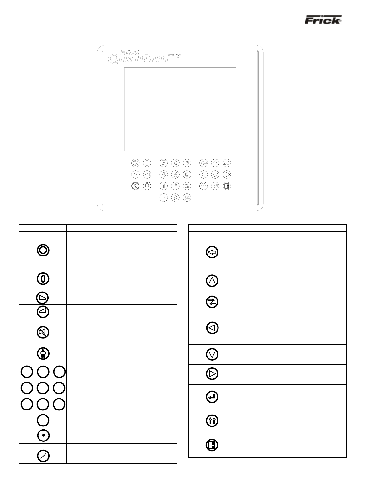
KEYS AND KEY FUNCTIONS
The following is a list of the labeled keypad keys and the actions that occur when they are pressed:
Key Function
[STOP] - When the compressor is
running in Manual Mode, pressing this
key immediately stops the compressor by
placing it into Stop Mode. The
compressor is stopped regardless of any
other conditions.
[START] - When in Manual Mode, this
key places the compressor unit into the
Start Mode for running.
[INCREASE
VALUE] - Increases
Capacity.
[DECREASE VALUE] - Decreases
Capacity.
[ALARM SILENCE] - Immediately
silences a sounding alarm and turns off
the alarm annunciation device that is
connected to this panel.
[MANUAL] - Changes the compressor
mode from its current mode to its
previous mode.
7
4
NUMERALS
[0] - [9] - The numerical
keys are used to enter a value in a data
1
2
field.
DECIMAL [.] - This key is used when
entering a decimal value in a data field.
[+/-] - When changing a value in a data
field, this key toggles the value between
negative and positive.
Key Function
[BACKSPACE] - Pressing this key will
cause the current location of the cursor to
backup one position per key depression.
When changing a value in a data field,
this key will delete the selected
character.
[UP ARROW] - Provides upward
navigation within the MAIN MENU
window.
[TAB] - When in the mode of changing
setpoints, pressing this key will cause the
cursor to jump to the next data entry field.
[LEFT ARROW] - When in the mode of
changing setpoints, this key is used to go
to the previous data entry field. When the
MAIN MENU is shown, pressing this key
will cancel the window.
[DOWN ARROW] - Provides downward
navigation within the MAIN MENU
window.
[RIGHT ARROW] - When in the mode of
changing a data entry field, this key is
used to go to the next character.
[ENTER] - When changing data in a data
entry field, this key will accept the
change. This key is also used to select
items on Menu Windows.
[SUBMIT] - After changing a setpoint
value, Use this key to enter (submit) the
change.
[MENU] - Shows the MAIN MENU
window. This window shows the main
selections for accessing information,
setup of options, and setpoint entry.
Page 5
®
g
g
y
FRICK
QUANTUM™ LX COMPRESSOR CONTROL PANEL S90-021 O (MAY 07)
OPERATION - ADVANCED Page 5
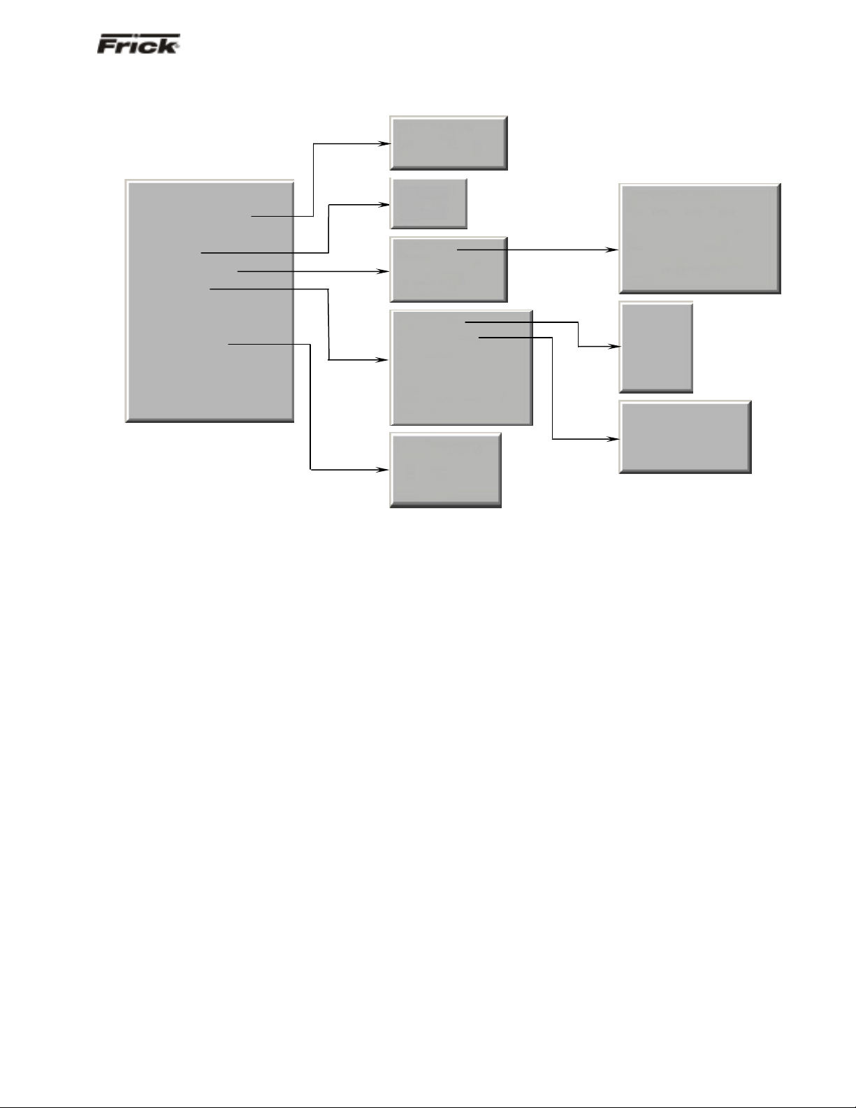
MENU STRUCTURE
Sequencing
User Defined
Home
Operating Values…
Modes
Safeties…
System Status…
Setpoints…
Calibration 1
Calibration 2
Configuration…
Session
Help
About
Current
History
Trending…
Maintenance
Event Lo
Capacity…
Sequencing…
Scheduling
Condenser
Communications
Panel
Compressor
Internet
Securit
The above graphic represents the menu structure, or tree,
of the Quantum™-LX screens. Use this tree when
accessing the various screens. When this document is
viewed electronically, passing the mouse pointer over
each of the above names, and then clicking on it, will take
Trending Setup
Real Time Trending
History Trending
Real Time Data Log
History Data Lo
Mode 1
Mode 2
Mode 3
Mode 4
System 1 Setup
System 2 Setup
System 3 Setup
you directly to the page with that screen. Please note that
this screen list is complete, and that certain screens may
not be available as shown here, depending upon the
enabled options.
Page 6
®
S90-021 O (MAY 07) FRICK
QUANTUM™ LX COMPRESSOR CONTROL PANEL
Page 6 OPERATION - ADAVNCED
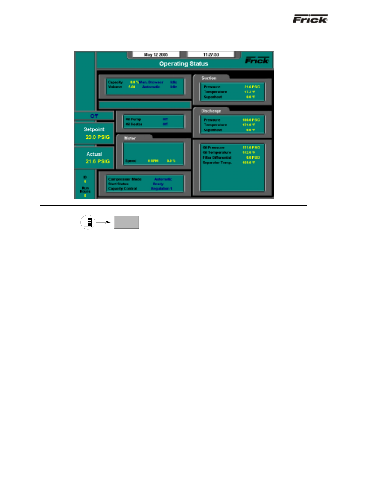
OPERATING DISPLAY SCREENS
Operating Status
SCREEN NAME: Operating Status or Home.
ACCESSING:
Home
DESCRIPTION: This is the default screen. When power is applied, this screen will appear. Also called the
Home screen. The most important information about the compressor and the applicable subsystems
operation is displayed here. This screen is shown when power is first turned on and wh en a key is pressed
after the screen saver has turned off the backlight. The Operating Status screen is continuously updated
and provides a variety of information with regard to the current condition and performance of the compres sor
unit and subsystem.
The following information is shown on this screen:
DATE - The actual date will be displayed in this box.
The date must first be set correctly on the
Configuration screen. Once set, the date will be
automatically adjusted for at the end of each month,
much like the calendar feature of most modern
watches. The primary use of the date feature is to
provide a date stamp for Warnings and Shutdowns.
(See also TIME)
TIME - The actual time will be displayed in this box.
The time must first be set correctly on the
Configuration screen. The time will also need to be
adjusted for those locations which observe Daylight
Savings Time. The primary use of the time feature is
to provide a time stamp for Warnings and Shutdowns.
(See also Date)
SCREEN TITLE - This is the title for the screen that is
showing. Each screen will have a title. The
Quantum™ LX manuals will extensively refer to
screens by these names. When referred to in these
manuals, screen names will be shown in bold italic
print, such as Operating Status.
COMPRESSOR MODEL - This is actually a rotating
marquee. It will alternately display the model name of
the compressor (such as RWF) and will then rotate to
show Frick
®
.
COMPRESSOR RUN STATUS -
• Off
• Running
• Starting
• Stopping
• Stopping - High Capacity
• Stopping - Pumpdown
PROCESS SETPOINT VALUE - This is the control
setpoint maintained by the internal capacity control.
PROCESS ACTUAL VALUE - The actual reading of
the pressure or temperature that was chosen as the
compressor control setpoint.
ID - The value shown here is the number that has
been assigned to this particular unit on the
Communications Setup screen.
RUN HOURS – The value shown here is the total
number of hours that the compressor has been
actually running, since the last start.
Page 7

®
FRICK
QUANTUM™ LX COMPRESSOR CONTROL PANEL S90-021 O (MAY 07)
OPERATION - ADVANCED Page 7
CAPACITY/VOLUME CONTROL BOX - Shows what
is presently controlling the Slide Valve and from what
source it was initiated. The following sources may be
shown:
Capacity:
• Manual
• Automatic
• Remote -- Communications
• Remote -- IO
• Remote -- 4-20 Input
• Remote -- Sequencing
VOLUME:
• Manual
• Automatic
WARNING/SHUTDOWNS STATUS BOX - The
Warning/Shutdowns Status is displayed in the
indented box below the Capacity/Volume status box.
This status box is blank with no message if there are
no warnings or shutdowns present.
One of the following messages could be shown:
WARNING - This message flashes when a
warning is present. A warning is a condition that
requires operator acknowledgement and allows
the compressor to continue to run if it is running.
SHUTDOWN - This message flashes when a
shutdown is present. A shutdown is a condition
that requires an operator to acknowledge it and
causes the compressor to shut down. If the
compressor cannot be stopped, it is minimally run
in a protected state.
A Warning or Shutdown message indicates a
Warning or Shutdown point has been
reached, or exceeded.
When a Shutdown occurs, the display
backlight will flash on and off to alert an
operator of the shutdown. This visual alarm
will help get the attention of the operator in a
noisy engine room environment where
audible alarms may not be heard. Pressing
any key on the keypad will clear the flashing
backlight.
OIL LUBRICATION DEVICE STATUS BOX - The
operating status is shown for the following devices:
Oil Pump - (If selected in the Configuration) –
The On or Off message is shown for the status of
the oil pump. The Manual or Auto message is
shown to indicate the position of the HAND-OFFAUTO switch. If dual pump control was enabled
in Configuration, the lead pump (either Oil Pump
1 or Oil Pump 2) is shown.
Oil Heater - The On or Off message is shown for
the status of the oil separator heater(s).
MOTOR STATUS BOX - The following items are
shown:
Motor Amps - The actual amps.
%FLA - The percentage of the drive motor full
load amperage rating that the motor is currently
using. % (FLA x SF)
Kilowatts - This is the estimated value of the
kilowatt usage of the compressor motor. It is
based on the calculation of Motor Amps * Volts *
2
3
/ 1000.
Recycle Delay - This message shows the
remaining time in minutes for Recycle Delay. If
the compressor has started and shuts down
within the recycle time delay setpoint period, the
Recycle Delay will prevent the compressor from
starting until the delay time expires. This time
delay is intended to prevent damage to the
compressor motor from successive restarts.
Note: The remaining recycle delay time can
be cleared from the Motor screen
COMPRESSOR STATUS BOX - Shows the present
operating status of the compressor and from what
source it has been initiated:
Compressor Mode - One of the following
messages is shown:
• Manual - A compressor manual start or
stop command was sent.
• Automatic - The compressor auto
command was sent. The compressor
starting and stopping is being controlled
from automatic cycling control setpoints
at the panel. The automatic cycling
control setpoints of the active capacity
control are used.
• Remote -- Communications - The
compressor remote communications
command was sent. The compressor
starting and stopping is through the
serial Com-2 channel.
• Remote -- IO - The compressor remote
I/O command was sent.
• Remote -- Sequencing - The
compressor remote sequencing
command was sent.
Note: If there is a shutdown in response to a
safety setting, a compressor in Remote or
Automatic mode is placed i nto Manual mode
requiring operator intervention.
Start Status - One of the following messages is
shown:
• Ready
• Start Inhibit In Shutdown
Page 8

®
S90-021 O (MAY 07) FRICK
QUANTUM™ LX COMPRESSOR CONTROL PANEL
Page 8 OPERATION - ADAVNCED
• Start Inhibit In Recycle Delay
• Start Inhibit High Discharge Temp.
• Start Inhibit High Oil Temperature
• Start Inhibit Low Separator Temperature
• Start Inhibit Slide Valve Too High
• Start Inhibit Still In Prelube
• Start Inhibit High Suction Pressure
• Start Inhibit High Suction/Discharge
Differential Start Inhibit Permissive Start
• Start Inhibit Digital Auxiliaries
• Power Fail Restart
Capacity Control - One of the following
messages is shown:
• Regulation 1
• Regulation 2
• Regulation 3
• Regulation 4
SUCTION PRESSURE & TEMPERATURE BOX The following sensor information is displayed:
Suction Pressure - Is measured at the
compressor inlet and the value is displayed along
with the unit of measure.
Suction Temperature - Is measured at the
compressor inlet and the value is displayed along
with the unit of measure.
Superheat - The temperature of the gas at
saturation temperature for a given period of time.
DISCHARGE PRESSURE & TEMPERATURE BOX The following sensor information is displayed:
Discharge Pressure - Is measured at the
compressor outlet and the value is displayed
along with the unit of measure.
Discharge Temperature - Is measured at the
compressor outlet and the value is displayed
along with the unit of measure.
Superheat - Superheat is the term used to
describe the difference between the vapor point
(ie., the temperature at which the refrigerant
evaporates at a given pressure) and the actual
temperature of the refrigerant exiting the
evaporator coil.
OTHER PRESSURES AND TEMPERATURE BOX The following sensor information is displayed:
Oil Pressure - Is measured prior to entering the
compressor and the value is displayed along wit h
the unit of measure.
Oil Temperature - Is measured prior to entering
the compressor and the value is displayed along
with the unit of measure.
Filter Differential - If applicable, pressure drop
across the oil filter. The main oil injection oil filter
pressure drop value (differential) is displayed
along with the unit of measure.
Separator Temperature - The Oil Separator
Temperature value is displayed along with the
unit of measure.
Process Temperature - If applicable, the
Leaving Process Temperature value is displayed
along with the unit of measure.
Balance Piston - If applicable, the Balance
Piston pressure reading is displayed along with
the unit of measure. This reading is a
measurement of the presence at the Balance
Piston.
Page 9
®
FRICK
QUANTUM™ LX COMPRESSOR CONTROL PANEL S90-021 O (MAY 07)
OPERATION - ADVANCED Page 9
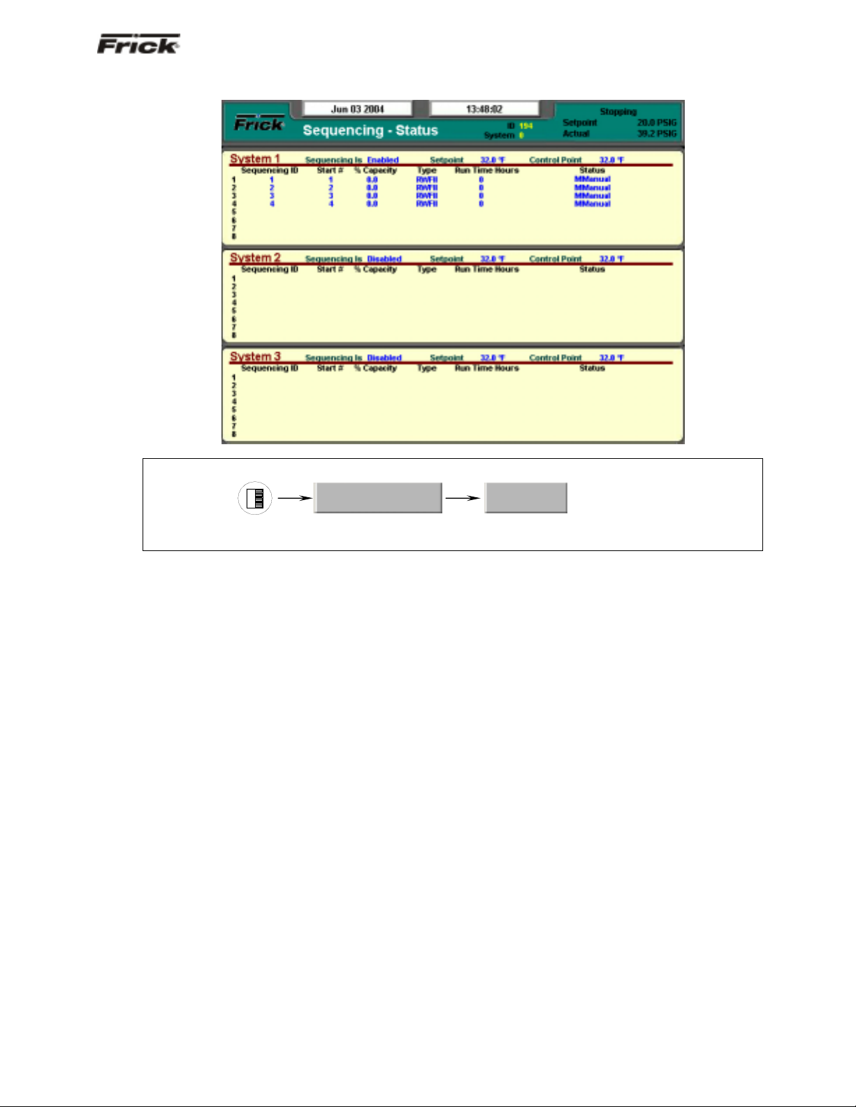
Sequencing
SCREEN NAME: Sequencing.
ACCESSING:
Operating Values…
DESCRIPTION: This screen will be available if Sequencing is enabled in Compressor configuration. This is
strictly a status screen, no values can be changed from here.
The following is a description of the Sequencing strategy:
Start/Stop
System Setup:
• Control Input – Suction Pressure
• Control Direction – Forward
• High Stage Link – Disabled
Start Procedure
Before starting a compressor, the master must
determine that all the running compressors are loaded
and that the Suction Pressure has risen to a point
where an additional compressor is needed.
First, the master checks that either no compressors
are running or all the running compressors average
90% capacity. If a running compressor is at less than
90% capacity but is in a Load Inhibit or Force Unload
condition, for the purposes of this calculation it is
assumed to be at 90% capacity.
If all the running compressors are loaded the master
next begins comparing its Suction Pressure to the
Autocycle Start setpoint. When the Suction Pressure
rises above the Start setpoint, the start timer is
initiated. If the start timer reaches the Autocycle Start
Delay setpoint time and the Suction Pressure has
remained above the Start setpoint for the entire time,
the master attempts to start an additional compressor.
If the Autocycle Start Delay setpoint is 0 minutes, the
Sequencing
master still waits 15 seconds before starting a
compressor.
To determine which compressor to start, the master
first sorts all the compressors in the system based on
their start number, low to high. If two compressors
have the same start number, the first one on the list
remains ahead of the second. Next, the master starts
at the top of the list and works down through list until
it finds a compressor that is available to run. To be
deemed available, a compressor must have good
sequencing communications and its Compressor
Mode and Capacity Mode must be set as Remote
Sequencing. In addition the compressor must be off,
and it cannot be in a Start Inhibit condition except for
the Start Inhibit Slide Value Too High condition. The
compressor with the lowest start number that also
meets these conditions is then sent a start command.
If no compressors are currently available to start, the
master will continue checking until one becomes
available or until the Suction Pressure drops below
the Start setpoint.
After a compressor has been sent a start command,
the master waits for that compressor to reach a
Running state. If 3 minutes passes and the
compressor has not yet begun to run, the master
sends it a stop command. This compressor is then
flagged as Unable to Start for 1 hour. After that time
the master may again try to restart the compressor if
additional capacity is needed. After a compressor
begins running or after one fails to start and is sent a
Page 10

®
S90-021 O (MAY 07) FRICK
QUANTUM™ LX COMPRESSOR CONTROL PANEL
Page 10 OPERATION - ADAVNCED
stop command, the master can begin the process of
starting another compressor.
Stop Procedure
If the Suction Pressure drops to a point where one of
the running compressors is no longer needed, the
master will stop the last compressor in the sequence
list.
When the Suction Pressure drops below the
Autocycle Stop setpoint, the stop timer is initiated. If
the stop timer reaches the Autocycle Stop Delay
setpoint time and the Suction Pressure has remained
below the Stop setpoint for the entire time, the master
attempts to stop one of the running compressors. If
the Autocycle Stop Delay setpoint is 0 minutes, the
master still waits 15 seconds before stopping a
compressor.
To select the compressor to stop, the master also
sorts all the compressors in the system according to
their start number. Then the master starts at the
bottom of the list and works up, looking for a running
compressor that can be stopped. To be selected a
compressor must have good sequencing
communications and its Compressor Mode and
Capacity Mode must be set as Remote Sequencing.
In addition, the compressor’s run time must be greater
than the compressor’s Minimum Run Time setpoint. If
the Minimum Run Time setpoint is 0 minutes, a
compressor can also be stopped if it is still in Starting
mode. The compressor with the highest start number
that meets these conditions is sent a stop command.
If no compressors are currently available to stop, the
master will continue checking until one becomes
available or until the Suction Pressure rises above the
Stop setpoint.
After a compressor has been sent a stop command,
the master waits for that compressor to go to off. If 3
minutes passes and the compressor has not yet
turned off, the master then flags this compressor as
Unable to Stop for 1 hour. After that time the master
may again try to stop the compressor. After a
compressor goes to off or after one fails to stop within
3 minutes, the master can begin the process of
stopping another compressor.
Load/Unload
System Setup:
Control Input – Suction Pressure
Control Direction – Forward
High Stage Link – Disabled
Load Procedure
If the master compressor’s Suction Pressure is above
the Capacity Control setpoint, the master calculates
the increase in capacity that is required. The
calculation is as follows:
Difference = Suction Pressure – (Capacity
Control Setpoint + Upper Dead Band)
If the Difference is less than the Upper Proportional
Band:
Capacity Change = (Difference / Upper
Proportional Band) * Upper Cycle Time
If the Difference is greater than the Upper
Proportional Band:
Capacity Change = Upper Cycle Time
After the capacity increase has been calculated, the
master then finds the compressor whose capacity
should be changed. To make this determination, the
master sorts all the compressors based on their start
number. Beginning at the compressor with the lowest
start number, the master finds the first compressor on
the list that is running but is not at its maximum
capacity. A compressor is at maximum capacity if it is
at 100 percent capacity or if it is in a Load Inhibit or
Force Unload condition.
If the selected compressor is running the Quantum LX
software, the capacity increase is added to the
compressor’s current capacity. This new value is then
sent to the compressor as its Capacity Command,
and that compressor will try to increase its capacity to
match the Command value.
If the selected compressor is controlled by a Quantum
1-4 or a Plus panel, the capacity increase is
interpreted as the time period for a load pulse and is
sent to the compressor as a load command. The
slave compressor will then turn on its load output for
the given number of seconds.
Unload Procedure
If the master compressor’s Suction Pressure is below
the Capacity Control setpoint, the master calculates
the decrease in capacity that is required. The
calculation is as follows:
Difference = (Capacity Control Setpoint - Upper
Dead Band) – Suction Pressure
If the Difference is less than the Lower Proportional
Band:
Capacity Change = (Difference / Lower
Proportional Band) * Lower Cycle Time
If the Difference is greater than the Lower
Proportional Band:
Capacity Change = Lower Cycle Time
After the capacity decrease has been calculated, the
master then finds the compressor whose capacity
should be changed. To make this determination, the
master sorts all the compressors based on their start
number. Beginning at the compressor with the highest
start number, the master finds the last compressor on
the list that is running and whose capacity is above its
Minimum Capacity setpoint. If two compressors are
currently running at or below their Minimum Capacity
setpoints, the master will not allow any additional
Page 11

®
FRICK
QUANTUM™ LX COMPRESSOR CONTROL PANEL S90-021 O (MAY 07)
OPERATION - ADVANCED Page 11
compressors to unload. This will allow the Suction
Pressure to continue to drop and will cause the
master to turn off one of the unloaded compressors. If
the master sees that only one compressor is running
in its system, it will continue to unload the compressor
down to the master’s Automatic Capacity Mode
Minimum Slide Valve Position setpoint.
If the selected compressor is running the Quantum LX
software, the capacity decrease is subtracted from the
compressor’s current capacity. This new value is then
sent to the compressor as its Capacity Command,
and that compressor will try to decrease its capacity
to match the Command value.
If the selected compressor is controlled by a Quantum
1-4 or a Plus panel, the capacity decrease is
interpreted as the time-period for an unload pulse and
is sent to the compressor as an unload command.
The slave compressor will then turn on its unload
output for the given number of seconds.
High Stage/Booster
The High Stage System Link setpoint is provided to
tie a system of Booster compressors to a system of
High Stage compressors. For example, if the Booster
compressors are setup on System #1 and the High
Stage Compressors are on System #2, the High
Stage System Link setpoint from System #1 would be
set as System 2.
When the Booster System’s master wants to start the
first Booster compressor, it first checks that a Booster
compressor is available to run and then sends a
signal to the High Stage System’s master telling it to
start a High Stage compressor. If all the High Stage
compressors are off, the High Stage System’s master
will start its first compressor, regardless of what the
High Stage Control Input is reading. When the
Booster System’s master observes that a High Stage
compressor is running, it will allow a Booster
compressor to start.
After the first High Stage compressor begins to run,
compressors in both systems will cycle on and off as
their Control Inputs move up and down. The only
stipulation to the control strategy is that one High
Stage compressor must always remain on as long as
at least one Booster compressor is running. If all the
Booster compressors turn off, the High Stage
compressor can then turn off as well.
Page 12
®
S90-021 O (MAY 07) FRICK
QUANTUM™ LX COMPRESSOR CONTROL PANEL
Page 12 OPERATION - ADAVNCED
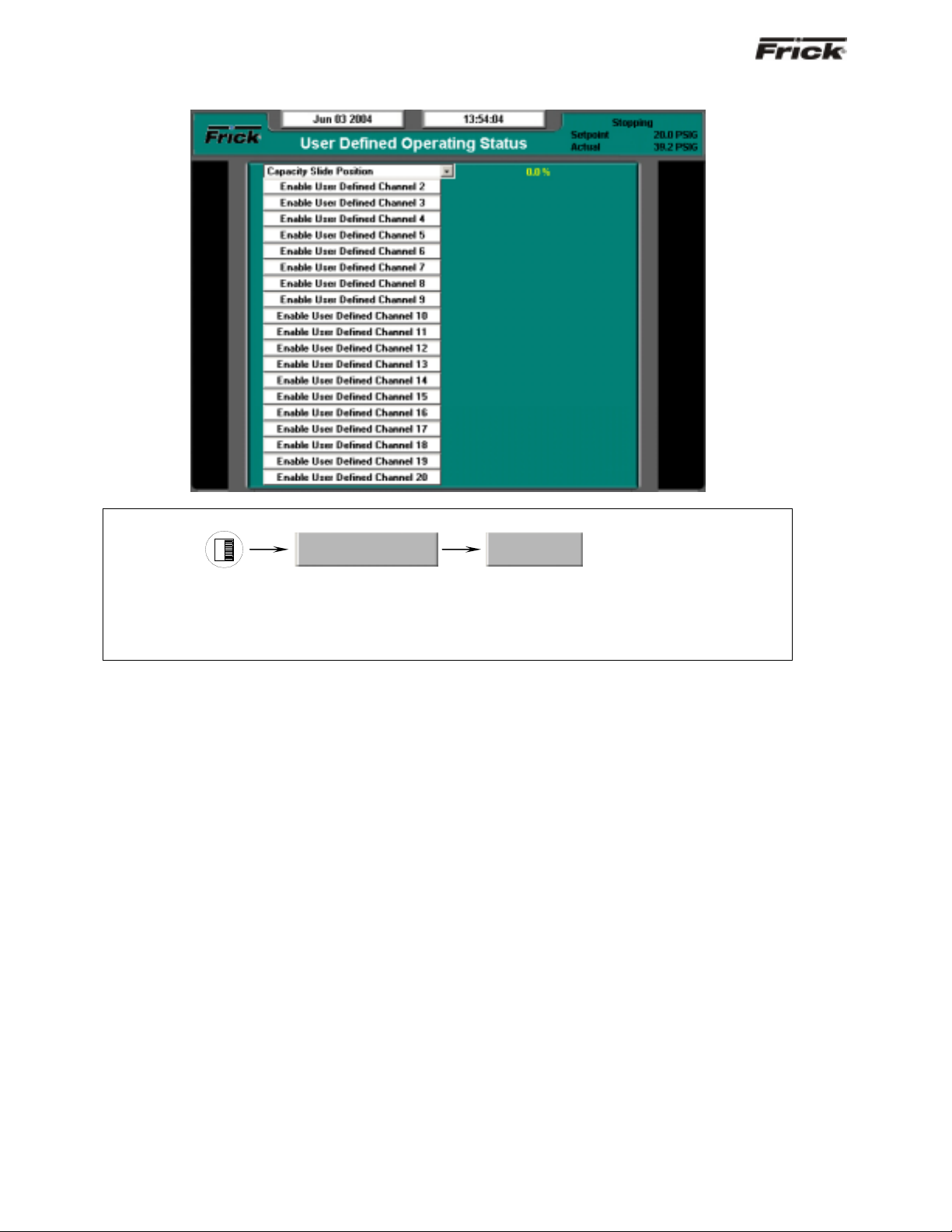
User Defined Operating Status
SCREEN NAME: User Defined Operating Status.
ACCESSING:
Operating Values…
DESCRIPTION: The purpose of this screen is to allow the user to assign additi onal analog channels to be
more readily viewable. Since the main Operating Status (Home) screen is capable of only showing a
limited number of pre-assigned analog values, it may be desirable for the user to have a method of viewin g
additional information that they can select, on a common screen. They may even select values that are
already being displayed on the Operating Status screen, as well as values that are not shown there.
As an example of how this screen works, assume that in
addition to the data that is shown on the Operating
Status screen, the user would like to monitor the Capacity
Slide Position, Suction Pressure and Motor Current.
Notice that both the Suction Pressure and the Motor
Current are already shown on the Operating Status
screen, but the user would also like to see Capacity Sli de
Position on the same screen as these other two. In order
to set this screen up this way, the user would highlight the
Enable User Defined Channel 1 (or whatever channel they
wish to use), by pressing the [Tab] key. Once the box is
highlighted, use the [Enter] key to cause the possible
settings for the channel to appear. Use the arrow keys to
scroll through the list. When the selection that you want to
use has been highlighted, press the [Enter] key to select
it. Once selected, a value will appear to the right of the list,
which corresponds to the analog value for that channel.
The following selections may be shown on this screen:
• Capacity slide position
• Volume slide position
• Suction pressure
• Discharge pressure
User Defined
• Oil pressure (Compressor)
• Main Oil Injection pressure
• Economizer pressure
• Filter pressure
• Intermediate pressure
• Balance piston pressure
• System discharge pressure
• Suction temperature
• Discharge temperature
• Oil temperature compressor
• Oil separator temperature
• Process/Brine temperature leaving
• Process/Brine temperature entering
• Motor Current
• RPM
• User defined analog inputs #1 - #20
• Compressor Vibration - Suction
• Compressor Vibration - Discharge
• Motor Vibration - Shaft Side
• Motor Vibration - Opposite Shaft Side
• None
Page 13
®
FRICK
QUANTUM™ LX COMPRESSOR CONTROL PANEL S90-021 O (MAY 07)
OPERATION - ADVANCED Page 13
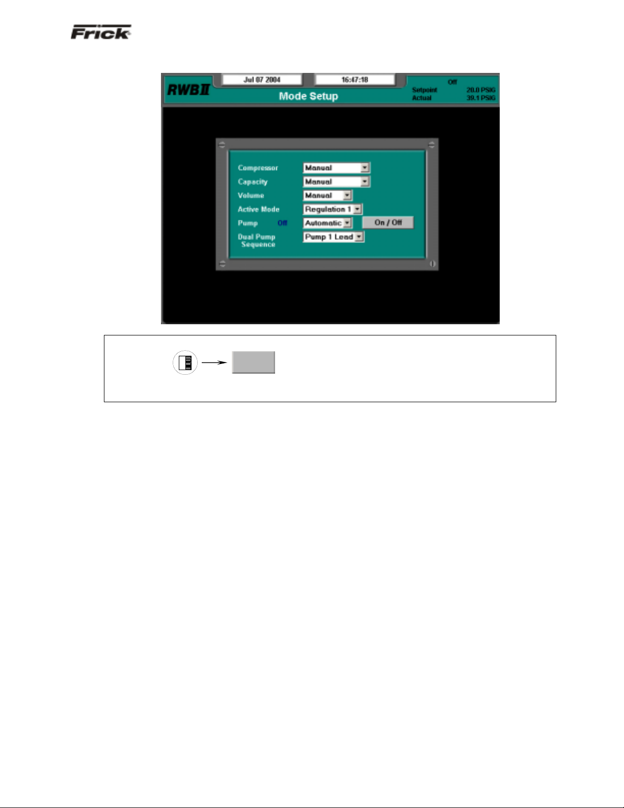
Mode Setup
SCREEN NAME: Mode Setup.
ACCESSING:
Mode
DESCRIPTION: The purpose of this screen is to allow the user to assign operational sta tes (such as m anu al
or automatic) to the various modes shown on the screen.
The following pull-down menus are shown here:
Compressor:
• Manual
• Automatic
• Remote -- Communications
• Remote -- IO
• Remote -- Sequencing
Capacity:
• Manual
• Automatic
• Remote -- Communications
• Remote -- IO
• Remote -- 4-20 Input
• Remote -- Sequencing
Volume:
• Manual
• Automatic
Active Mode:
• Regulation 1
• Regulation 2
• Regulation 3
• Regulation 4
Pump (if enabled):
A Pump On/Off indicator (blue text) is provided here
to alert the user as to the actual status of the Oil
Pump (if applicable). A drop down menu is also
provided, and there are two states that can be
selected for oil pump operation, they are:
• Manual
• Automatic
In Manual mode, the user has control over the
running of the pump. To run the pump, simply
observe the blue text indicator to ensure that the
pump is not already running, and if not, then press the
[On/Off] toggle button. The blue text indicator will
change from Off to On. To stop the pump, press the
toggle button again, and the pump indicator will
change to Off.
If the pump is set to Automatic mode, the Quantum™
LX software program is controlling the pump
operation. In this mode, if the toggle key is pressed,
the mode will be changed from Automatic to Manual
Mode, and the current state of the pump (digital
output 3) will toggle also.
Dual Pump Sequence (if enabled):
• Pump 1 Lead
• Pump 2 Lead
Page 14
®
S90-021 O (MAY 07) FRICK
QUANTUM™ LX COMPRESSOR CONTROL PANEL
Page 14 OPERATION - ADAVNCED
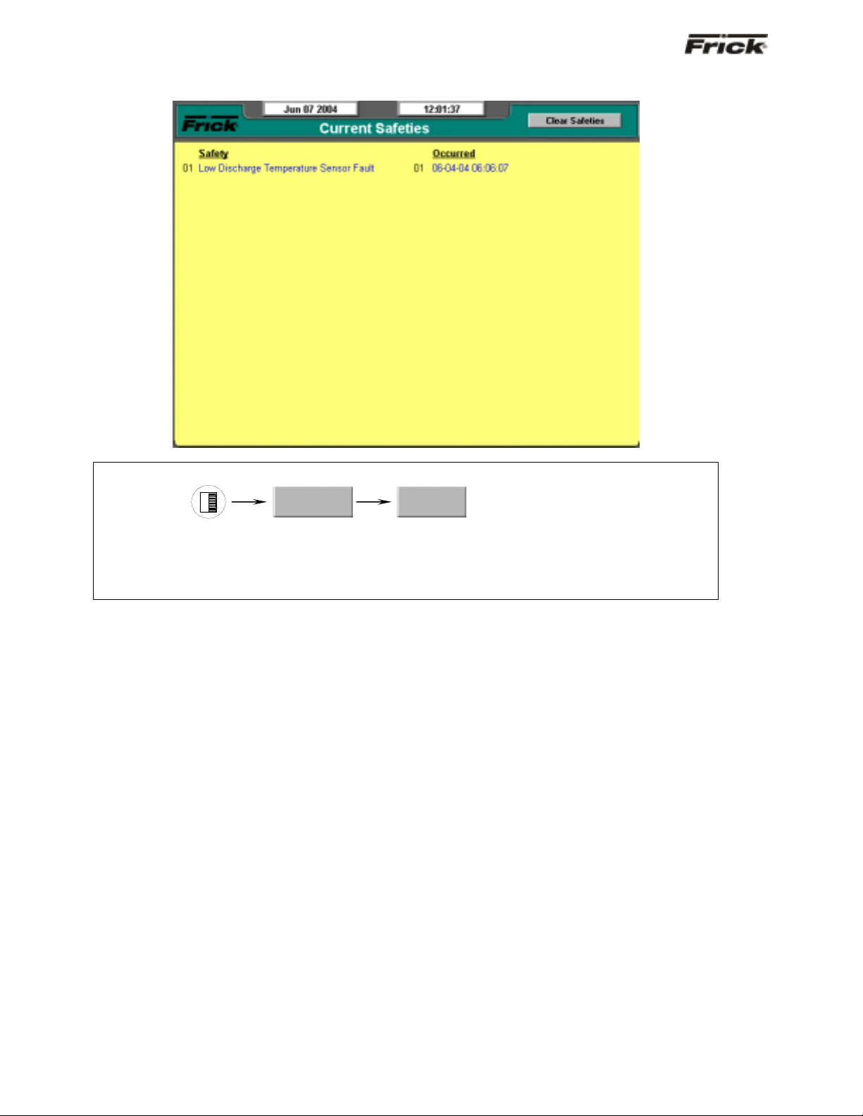
Safeties - History - Current Safeties
SCREEN NAME: Current Safeties.
ACCESSING:
Safeties…
DESCRIPTION: The Current Safeties screen shows the Warnings and Shutdowns that have recently
occurred (up to 50). When a warning or shutdown is triggered, a blue descriptive message shows on thi s
screen. The date and time of the warning or shutdown occurrence is shown to the right of its description.
The most recent message will appear on the top line of the screen with the oldest appearing at the bottom.
When a Warning or Shutdown is logged to this screen, it will also be logged to the Safety History screen.
The following Current Safeties screen key is provided:
[Clear Safeties] - Selecting this key will clear all
warnings and/or shutdowns from this screen. It also
de-energizes the Warning and Shutdown output
modules (digital outputs 23 and 24) to silence any
warning annunciation device. This will also place a
date/time stamp for the corresponding entry on the
Safety History screen showing that the particular
Warning or Shutdown was cleared. Clearing the entry
on the Current Safeties screen, will not clear it from
the Safety History screen.
To resume normal operation it will be necessary to go
through the following steps:
1. Correct the condition(s) causing the warning.
2. Press the [ALARM SILENCE] key. (This action
may precede correcting the condition(s) causing
the warning). Or, go to step 3.
3. To clear or reset the Warnings/Shutdowns
screen and turn off any warning annunciation
Current
device, from the screen, press the [Clear
Safeties] key. This will also clear the WARNING
or SHUTDOWN message from the Operating
Status screen.
4. If the conditions causing the warning have not
been corrected or a new fault has occurred, a
new WARNING or SHUTDOWN message will
appear. The Safety History screen keeps a
record of the warnings and shutdowns. This
information will help troubleshoot persistent
operational problems.
Refer to the Warnings/Shutdowns Message section for a
list of all the possible conditions.
When a Shutdown occurs, the screen backlight will flash
on and off to alert an operator of the shutdown. This visual
indication will help get the attention of the operator in a
noisy engine room environment where audible alarms may
not be heard. Pressing any key on the keypad will clear
the flashing backlight.
Page 15
®
FRICK
QUANTUM™ LX COMPRESSOR CONTROL PANEL S90-021 O (MAY 07)
OPERATION - ADVANCED Page 15
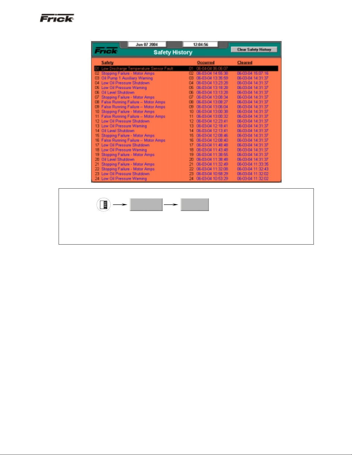
Safeties - History - Safety History
SCREEN NAME: Safety History.
ACCESSING:
Safeties…
History
DESCRIPTION: The Safety History screen shows the warnings and shutdowns that have recently occurred
(up to 50 maximum). When a warning or shutdown is triggered, a blue descriptive m essage shows on this
screen. The date and time of the warning or shutdown occurrence is shown to the right of its description,
followed by the date and time that the safety was cleared (if applicable, from the Current Safeties screen).
The most recent message will appear on the top line of the screen with the oldest appearing at the bottom.
Page 16
®
S90-021 O (MAY 07) FRICK
QUANTUM™ LX COMPRESSOR CONTROL PANEL
Page 16 OPERATION - ADAVNCED
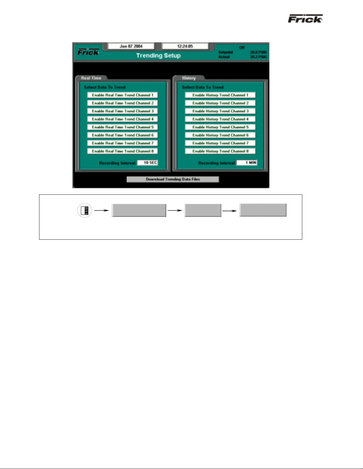
System Status -Trending - Trending Setup
SCREEN NAME: Trending Setup.
ACCESSING:
System Status…
DESCRIPTION: This is the Trending Setup screen. Up to eight channels can be monitored in real time
fashion (as the values are changing), and up to eig ht channels monitored as a history (l ong after they have
happened).
The following setpoints are provided:
Real Time Recording Interval – The time interval
that defines how often the trending data values are
recorded.
History Recording Interval – The time interval that
defines how often the trending data values are
recorded.
To program this screen with the data you wish to trend,
the user would highlight the Enable Real Time Trend
Channel 1 (or whatever channel they wish to use), by
pressing the [Tab] key. Once the box is highlighted, use
the [Enter] key to cause the possible settings for the
channel to appear. Use the arrow keys to scroll through
the list. When the selection that you want to use has been
highlighted, press the [Enter] key to select it. Once
selected, the value for this channel will be automatically
trended and shown on the Real Time Trending graph ( or
History Trending Graph), as well as on the Real Time
Trending Data Log (Or History Trending Data Log).
The following list is the selectable values that may be
shown on this screen:
• Capacity slide position
• Volume slide position
• Suction pressure
Trending…
Trending Setup
• Discharge pressure
• Oil pressure (Compressor)
• Main Oil Injection pressure
• Economizer pressure
• Filter pressure
• Intermediate pressure
• Balance piston pressure
• System discharge pressure
• Suction temperature
• Discharge temperature
• Oil temperature compressor
• Oil separator temperature
• Process/Brine temperature leaving
• Process/Brine temperature entering
• Motor Current
• RPM
• User defined analog inputs #1 - #20
• Compressor Vibration - Suction
• Compressor Vibration - Discharge
• Motor Vibration - Shaft Side
• Motor Vibration - Opposite Shaft Side
• None
The following screen command keys are provided:
Download Data Trending Files -
Page 17
®
FRICK
QUANTUM™ LX COMPRESSOR CONTROL PANEL S90-021 O (MAY 07)
OPERATION - ADVANCED Page 17
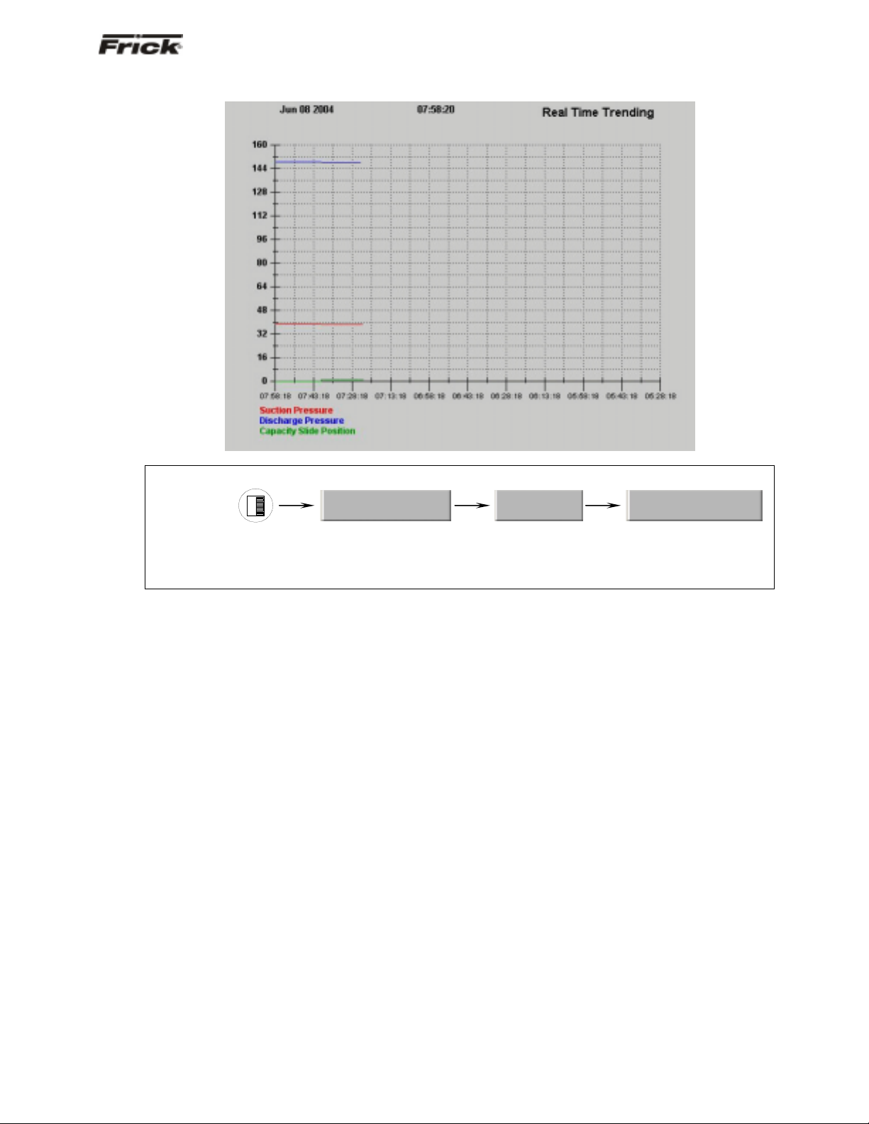
System Status -Trending - Real Time Trending
SCREEN NAME: Real Time Trending
ACCESSING:
System Status…
Trending…
Real Time Trending
DESCRIPTION: This is the Real Time Trending screen. This screen will display in a graphical chart format,
the data values as selected on the Real Time Trending Setup screen. Each of the possible eight selectable
channels will be shown at the bottom of the screen, each in a different color. The color data values displayed
in the chart, correspond to the matching color of the trending channels at the bottom of the screen.
Page 18

®
S90-021 O (MAY 07) FRICK
QUANTUM™ LX COMPRESSOR CONTROL PANEL
Page 18 OPERATION - ADAVNCED
System Status -Trending - History Trending
SCREEN NAME: Real Time Trending
ACCESSING:
System Status…
Trending…
History Trending
DESCRIPTION: This is the History Trending screen. It is accessible from the Main Menu by pressing
System Status…, then Trending, and finally History Trending. This screen will display in a graphical chart
format, the data values as selected on the Real Time Trending Setup screen. Each of the possible eight
selectable channels will be shown at the bottom of the screen, each in a different color. The color data
values displayed in the chart, correspond to the matching color of the trending channels at the bottom of the
screen.
Page 19

®
FRICK
QUANTUM™ LX COMPRESSOR CONTROL PANEL S90-021 O (MAY 07)
OPERATION - ADVANCED Page 19
System Status -Trending - Real Time Data Log
SCREEN NAME: Real Time Data Log.
ACCESSING:
System Status…
Trending…
Real Time Data Log
DESCRIPTION: This screen will display in a tabular format, the numerical data values as selected on the
Real Time Trending Setup screen. Each of the possible eight selectable channels will be shown at the
bottom of the screen, each in a different color. The color data values displayed in the chart, correspond to
the matching color of the trending channels at the bottom of the screen.
Page 20

®
S90-021 O (MAY 07) FRICK
QUANTUM™ LX COMPRESSOR CONTROL PANEL
Page 20 OPERATION - ADAVNCED
System Status -Trending - History Data Log
SCREEN NAME: History Data Log.
ACCESSING:
System Status…
Trending…
History Data Log
DESCRIPTION: This screen will display in a tabular format, the numerical data values as selected on the
Real Time Trending Setup screen. Each of the possible eight selectable channels will be shown at the
bottom of the screen, each in a different color. The color data values displayed in the chart, correspond to
the matching color of the trending channels at the bottom of the screen.
Page 21

®
FRICK
QUANTUM™ LX COMPRESSOR CONTROL PANEL S90-021 O (MAY 07)
OPERATION - ADVANCED Page 21
System Status - Maintenance
SCREEN NAME: Maintenance.
ACCESSING:
System Status…
DESCRIPTION: Using this screen, the user can view up to nine (9) pre-programmed maintenance
schedules, as well as eight (8) user definable maintenance schedules. Each of the user defined sch edules
may be custom named. This screen is based upon the Maintenance Schedule that is provided in the IOM
manual for the specific compressor package.
The usage of this screen is that the user can assign up to
seventeen different areas of compressor operation that
they would like to schedule routine maintenance for. As an
example, the above screen shows a row labeled as Oil
Analysis. The next column (Service Every) on the same
row has a value of 10000 Hrs. The last column (Next
Scheduled At) of this row has a value of 1000 Hrs. When
the compressor is running, this time value is being
clocked. After 1000 hours of compressor run time, a
message will be generated and placed on the Event Log
screen. This particular message will read Maintenance --
Oil Analysis. This is to notify the operator that it is time to
have the Oil checked. At this point, the operator should
notify the proper maintenance personnel that the
appropriate maintenance be performed. The user should
access the Event Screen on a regular basis (perhaps once
per week) to review the information provided there.
Once the message has been entered in the Event Log,
the values for the row will be automatically updated, with
new values as predetermined by an internal programmed
maintenance schedule, based upon the type of
compressor. The values for the Next Scheduled at column
are based upon the Compressor Run Time hours (shown
at the bottom of this screen).
At the bottom of the left most column is the user defined
Maintenance Required column. This is where custom
names may be entered for the various items that the user
would like to track.
Maintenance
Modifying numerical values
To modify any of the numerical boxes on this screen,
simply use the [Tab] key to scroll down the lists, or
the [Left Arrow] key to scroll up the lists. When the
box that you wish to change is highlighted, you may
enter the new value using the numerical keys, then
press the [Enter] key to accept the value.
Modifying Text (User Defined) Boxes
To modify any of the text boxes on this screen, simply
use the [Tab] key to scroll down the lists, or the [Left
Arrow] key to scroll up the lists. When the box that
you wish to change is highlighted, use the [Up Arrow]
key. A new screen (Alpha) showing a numerical
keypad will appear. Refer to the Alpha screen
description for information on entering text messages.
Press the [Enter] key to accept the text. The user
may type in a custom name up to 20 characters long.
The following additional information is provided on this
screen:
Run Hours - The value shown here are the total
number of hours that the compressor motor has
actually been in the running state. This value can b e
reset (or changed to any value from 0 to 1,000,000
Hours) from the Panel screen.
Page 22

®
S90-021 O (MAY 07) FRICK
Page 22 OPERATION - ADAVNCED
QUANTUM™ LX COMPRESSOR CONTROL PANEL
System Status - Event Log
SCREEN NAME: Event Log.
ACCESSING:
DESCRIPTION: This screen is used to log certain messages and events that are generated through normal
unit operation. Occurrences such as normal power up and power down sequences, as well as all
maintenance schedule messages (see the Maintenance screen for more information on these messages).
The messages that appear on this screen cannot be
cleared, they will be stored indefinitely. The user can use
System Status…
Event Log
the arrow keys on the keypad to scroll down through the
list.
Page 23

®
FRICK
QUANTUM™ LX COMPRESSOR CONTROL PANEL S90-021 O (MAY 07)
OPERATION - ADVANCED Page 23
Setpoints - Capacity Control - Mode 1
SCREEN NAME: Capacity Control.
ACCESSING:
DESCRIPTION: The Mode 1 and Mode 2 screens are identical in appeara nce. All setpoints having to do
with Capacity Control, Autocylce, Regulation Safeties and Low Suction are found here.
CAPACITY CONTROL - The following setpoint boxes are
provided:
Setpoint - This setpoint is used to control the loading
and unloading of the compressor when the Slide
Valve Position is in the Automatic (AUTO) mode.
Proportional Band High - A band, measured in the
units of the Capacity Control setpoint, above the Dead
Band High, where proportional load control is used. If
the actual reading rises into this proportional band,
the load output will be pulsed as explained below in
the description about proportional band.
Proportional Band Low - A band, measur ed in the
units of the Capacity Control setpoint, below the Dead
Band Low, where proportional unload control is used.
If the actual reading falls into this proportional band,
the unload output will be pulsed as ex plaine d below i n
the description about proportional band.
A Note About Proportional Band: The
Proportional Band setpoint determines a range of
Capacity Control values where pulsed output is
used. Beyond the proportional band the output is
continuously energized. The length of time the
output will be pulsed on is proportional to the
distance the actual reading is from the Capacity
Control setpoint. The further the distance from
Setpoints…
Capacity…
Dead Band High - A band, measured in the units of
the Capacity Control setpoint, above the setpoint at
which the compressor will neither load nor unload.
Dead Band Low - A band, measured in the units of
the Capacity Control setpoint, below the setpoint at
which the compressor will neither load nor unload.
Cycle Time High - This setpoint determines the
amount of time in seconds that the load output is on
and off, when in the upper proportional band. Refer to
the above description about cycle time.
Cycle Time Low - This setpoint determines the
amount of time in seconds that the unload output is
on and off, when in the lower proportional band.
Refer to the above description about cycle time.
Mode1
setpoint, the longer the output is pulsed on and
the shorter the output is off. The closer the
distance to setpoint, the shorter the output is
pulsed on and the longer the output is off. If the
actual reading is midpoint from setpoint, the
output is on and off an equal amount of time.
A Note About Cycle Time: The Cycle Time
setpoint determines the amount of time the
output is on and off, when in the proportional
band. At the completion of the cycle time, the
Page 24

®
S90-021 O (MAY 07) FRICK
QUANTUM™ LX COMPRESSOR CONTROL PANEL
Page 24 OPERATION - ADAVNCED
actual reading and necessary response is reevaluated. If a four-second period has been
selected, then the following will result:
Proportional
Distance
Actual Reading
Output
Pulsed On
(sec)
Output Off
(sec)
is From Setpoint
0 0 4
1/4 1 3
1/2 2 2
3/4 3 1
1 4 0
The following status indicator is provided:
Channel - Shows which analog channel is bein g
used to control this mode. The possible states of
this indicator are:
• Capacity slide position
• Volume slide position
• Suction pressure
• Discharge pressure
• Oil pressure (Compressor)
• Main Oil Injection pressure
• Economizer pressure
• Filter pressure
• Intermediate pressure
• Balance piston pressure
• System discharge pressure
• Suction temperature
• Discharge temperature
• Oil temperature compressor
• Oil separator temperature
• Process/Brine temperature leaving
• Process/Brine temperature entering
• Motor Current
• RPM
• User defined analog inputs #1 - #20
AUTOCYCLE - The following setpoint boxes are
provided:
Start - The compressor is st arted at this setpoint
when it is under automatic control.
Start Delay - The minimum time in minutes that
the actual Capacity Control value must equal or
exceed the start autocycle (automatic cycling)
setpoint before the compressor will start. This
timer helps prevent cycling a compressor on and
off due to short or sudden changes in load within
the refrigeration system.
Stop- The compressor is stopped at this setpoint
when it is under automatic control.
Stop Delay - The minimum time in minutes that
the actual Capacity Control value must equal or
exceed the stop autocycle (automatic cycling)
setpoint before the compressor will stop. This
timer helps prevent cycling a compressor on and
off due to short or sudden changes in load within
the refrigeration system.
REGULATION SAFETIES - The following setpoint
boxes are provided:
• Load Inhibit
• Force Unload
• Warning
• Warning Delay
• Shutdown
• Shutdown Delay
Each of the four Regulation Modes has a set of
Regulation Safeties and Low Suction Safeties.
Additionally, each also has a Control Channel and is
configured with a Control Direction of either Forward
or Reverse. The Regulation Safety Setpoints monitor
the Control Channel for their Regulation Mode.
If the Control Direction for a Regulation Mode is set
to Forward, its Regulation Safeties are activated as
the Control Channel’s value drops below the
Regulation Safety Setpoints.
Example:
Control Channel = Process Temperature
Control Direction = Forward
Regulation Safety Warning Setpoint = 35.0 F
Note: For the above conditions a Regulation
Warning will occur if the Process Temperature
drops below 35.0 F.
If the Control Direction for a Regulation Mode is set to
Reverse, its Regulation Safeties are activated as the
Control Channel’s value rises above the Regulation
Safety Setpoints.
Example:
Control Channel = Discharge Pressure
Control Direction = Reverse
Regulation Safety Load Inhibit Setpoint = 170.0
PSIG
Note: For the above conditions a Regulation
Load Inhibit condition will occur if the Discharge
Pressure rises above 170.0 PSIG.
If a Regulation Mode’s Control Channel is set to
Suction Pressure, and its Control Direction is set to
Forward, then both the Regulation Safeties and the
Low Suction Safeties are checking for the same
conditions. In this case, it is recommended that one
group of safeties be set lower than the other group so
that only one group will be actively monitoring the
channel. Otherwise, duplicate Warning and
Shutdown messages would be shown that could be
confusing.
LOW SUCTION - The following setpoint boxes are
provided:
• Load Inhibit
• Force Unload
• Warning
• Warning Delay
• Shutdown
• Shutdown Delay
Page 25

®
FRICK
QUANTUM™ LX COMPRESSOR CONTROL PANEL S90-021 O (MAY 07)
OPERATION - ADVANCED Page 25
Setpoints -Sequencing - System 1 Setup
SCREEN NAME: Sequencing - System 1 Setup.
ACCESSING:
Setpoints…
DESCRIPTION: This screen will be available if Sequencing is enabled in Compressor configuration. The
screen shown here represents System 1. There are additionally a System 2 and a Sys tem 3 setup screen,
which are not discussed further here, as all three screens show the sa me layout, although they may get
setup using differently, using different capacity modes for example. Use these screens to setup all of the
necessary operating parameters for performing compressor sequenci ng. The information from these three
screens will be shown on the Sequencing Status screen.
The following pull-down menus and setpoint boxes are
shown here:
Sequencing - Use this menu to set the current
condition of System 1:
• Disabled - The compressors that are listed
on this screen will not run as part of the
sequencing scheme (System 1 will be
ignored).
• Enabled - The compressors that are listed
on this screen will run when called for as part
of the sequencing scheme (System 1 will be
included).
Setpoint - Use this setpoint box to set the value that
you wish all compressors within this System to
maintain.
Control Point - This is the actual value for the
capacity control (as measured from the Master
compressor). The master compressor is the unit with
the lowest number shown on the Start # list. It is to
this value that the compressors will attempt to
maintain. This is strictly a displayed value, and cannot
be changed here (it is based off of the Setpoint box
directly above it).
Sequencing…
System 1 Setup
Minimum Run Time - This is the minimum amount of
time that each compressor within this system will run,
when called upon to do so.
High Stage System Link - The High Stage System
Link setpoint is provided to tie a system of Booster
compressors to a system of High Stage compressors.
IP Address - Each compressor will have a different IP
Address. This value should be entered by the network
or LAN administrator, and will be shown here. Use the
last three digits of this number for setting the
Sequencing ID number for each compressor within
the system. For example, from the IP shown on this
screen, use 194 to enter into one of the eight
Sequencing ID boxes at the left of the screen. This
will identify which compressor is being communicated
to with sequencing instructions.
There are eight rows of setpoint boxes shown at the
bottom of this screen. These rows correspond to up to
eight different compressors, which combined will make up
this system. The user may program as few or as many of
these rows as their situation requires:
Sequencing ID - Enter the last three digits of the IP
Address here. This will identify each of the possible
eight compressors to the Master.
Page 26

®
S90-021 O (MAY 07) FRICK
QUANTUM™ LX COMPRESSOR CONTROL PANEL
Page 26 OPERATION - ADAVNCED
Start # - Use the values of 1 - 8 here. The lowest
number will identify which compressor is to be the
Master. If the Master is for some reason turned off,
the next lowest numbered compressor will become
the Master, and so on.
Compressor Mode -
• Manual
• Automatic
• Remote Comm
• Remote IO
• Remote Seq.
Capacity Mode -
• Manual
• Automatic
• Remote Comm
• Remote 4-20
• Remote IO
Panel Type - Set this pull-down for the type of
controller on each of the associated compressors. If
the panel type is the Quantum / Plus version, then
use the Panel ID for these units as the Sequencing
ID. Ensure that the ID numbers are all different. The
two selections are:
• Quantum LX
• Quantum / Plus
Minimum Capacity -
Page 27

®
FRICK
QUANTUM™ LX COMPRESSOR CONTROL PANEL S90-021 O (MAY 07)
OPERATION - ADVANCED Page 27
Setpoints -Scheduling
SCREEN NAME: Scheduling.
ACCESSING:
Setpoints…
DESCRIPTION: Scheduling allows the user to program up to four different operating schedules for each day
of the week. This can be a great way to save energy. At night or on weekends an d holidays, or even over
lunch periods when room doors are kept closed, or production is minimized, a higher temperature can be set
to reduce energy consumption.
This screen shows a time schedule. Up to four different
modes can be entered for each day of the week. The
Schedule is only effective if the compressor is in
automatic.
Notice that there are four columns of Hour/Minute entries,
each followed by a Regulation mode (1 - 4). Use the left
most column (on the row for the day of the week that you
wish to schedule) to enter the time of day that you would
like the compressor to switch form it’s normal operating
mode, into the scheduled mode. When that time of day
arrives, whatever mode the compressor WAS running in,
will be switched over to the scheduled (Regulation 1 -4)
mode. This mode will then be the active running mode,
and will continue to be the active mode until the time in the
following column is reached. If the time in the next colum n
is 00:00, it will be skipped.
The Schedule must be activated to switch the presently
active Regulation mode to the Scheduling regulation mode
at the assigned time. An entry of 00:00 will void the time
Scheduling
entry field. If setback is required at midnight (00:00) use
00:01.
The following drop down menu is provided:
Scheduling
• Enabled - The user programmed Schedule
will be followed.
• Disabled - The Quantum™ LX will ignore
any schedule that may have been set.
The following are descriptions of the setpoints:
Time Column - The time of day that you want to
switch to the Scheduled regulation setpoints of the
active capacity control.
Mode Column - Set this to the Regulation Mode (1 -
4) that you want to run at the assigned time.
Page 28

®
S90-021 O (MAY 07) FRICK
Page 28 OPERATION - ADAVNCED
QUANTUM™ LX COMPRESSOR CONTROL PANEL
Setpoints -Condenser
SCREEN NAME: Condenser.
ACCESSING:
DESCRIPTION: If Condenser is enabled, this screen allows the end user to enter and view the basic
operating parameters related to condenser operation.
Setpoints…
Condenser
Page 29

®
FRICK
QUANTUM™ LX COMPRESSOR CONTROL PANEL S90-021 O (MAY 07)
OPERATION - ADVANCED Page 29
Setpoints -Communications
SCREEN NAME: Communications configuration.
ACCESSING:
Setpoints…
DESCRIPTION: This screen is used to set the compressor ID number, and the parameters for each of the
three communications channels, as well as to show the status of the internal I/O board status.
The following setpoints are provided:
Compressor ID - A number that is used by an
external communications application, to converse to
individual compressors. On interconnected systems,
this number must be unique. Valid values are from 0 -
99.
Comm1 - (Setup parameter definitions for Comm1, 2,
and 3 are identical) Communications related
information for the communications ports:
Status - Shows the current communications
status of the port. The possible messages are:
• Off - No communications are currently
taking place. NOTE: A delay of 15
seconds or more of inactive
communications (time between valid
responses) will cause this message to
display.
• Active - Valid communications are
actively occurring.
• Failed - An invalid command was
received by the port. This could be due
to a bad checksum value, a wiring
issue, or hardware problem at either the
transmitting (host) or receiving
(Quantum™ LX) end.
Communications
Baud Rate - Allows for the following selections:
Data Bits - Allows for the following selections:
Stop Bits - Allows for the following selections:
Parity - Allows for the following selections:
RS-485 Connection - Allows for the following
selections:
Protocol - Allows for the following selections:
• 1200
• 2400
• 4800
• 9600
• 19200
• 38400
• 57600
• 115200
• 7
• 8
• 1
• 2
• None
• Even
• Odd
• No
• Yes
• None
• Frick
Page 30

®
S90-021 O (MAY 07) FRICK
QUANTUM™ LX COMPRESSOR CONTROL PANEL
Page 30 OPERATION - ADAVNCED
• ModBus ASCII
• ModBus RTU
• AB DF1 Full Duplex
• AB DF1 Half Duplex
• DBS Motor Starter
• Vyper
Map File - Allows for the following selections:
• No
• Yes
I/O Comms - A status indicator is provided to show
the current state of the internal communications of the
I/O boards. The possible displayed states are:
• Off
• Active
• Failed
Select this key to detect all connected Analog and
Digital boards. If a board has been removed, a
communication error shutdown will be issued until this
key is selected. Reference the About screen to view
what has been detected.
Setpoints - Panel
SCREEN NAME: Panel configuration.
ACCESSING:
Setpoints…
DESCRIPTION: This screen is used to view and set basic compressor operational values.
The following information is provided:
Panel Temperature - The main processor board is
equipped with a temperature sensor. The panel has
an operational temperature range that should be
maintained. The operational temperature range is
documented in the specifications document.
Panel Heater - A Status message is showing the
current state of the Panel Heater:
• Off - Panel Heater is Off
• On - Panel Heater is On
Whether the Panel Heater is On or Off is determined
by the setting of the following two setpoints:
• On - If the sensor on the main processor
board detects that the temperature is less
than or equal to this setpoint, the Panel
Heater output is turned on.
Panel
• Off - If the sensor on the main processor
board detects that the temperature is greater
than or equal to this setpoint, the Panel
Heater output is turned off.
The following pull-down boxes are provided:
Permissive Start Remote Enable Output Run Hours PLC Interlock Input Module Capacity Mode Selection -
• Disabled
• Enabled
Page 31

®
FRICK
QUANTUM™ LX COMPRESSOR CONTROL PANEL S90-021 O (MAY 07)
OPERATION - ADVANCED Page 31
Calibration 1
SCREEN NAME: Calibration 1.
ACCESSING:
Calibration 1
DESCRIPTION: This screen is used to view and set calibration values.
This screen should be used anytime a sensor is found to
be out of calibration. The recommended practice for
adjusting the calibration reading is to first determine which
sensor(s) need to be calibrated. Once this is determined,
you must know the actual reading that the sensor should
be showing, This can be accomplished by comparing the
displayed reading shown here, with the actual value using
a separate measurement device, such as a Digital Volt
Meter, or temperature probe, etc. Determine the difference
between what the screen reading for the sensor is, and
what the reading of the separate device shows. As an
example, assume that the Suction Temperature on this
screen reads 120° F, but a separate device is showing a
reading of 123° F. Highlight the setpoint box for Suction
Temperature, and enter the value of 123. The new readin g
will now read 123, and should match your separate
reading.
The following fields are provided:
Pressure - The following sensor values are
displayed along with the unit of measure:
Suction Pressure - This value is measured at
the compressor inlet .
Discharge Pressure - This value is measured at
the compressor outlet.
Oil Pressure - This value is measured prior to
entering the compressor.
Filter (Differential) - If applicable, shows the
pressure drop across the oil filter. The main oil
injection oil filter pressure drop value (differential)
is displayed along with the unit of measure.
Balance Piston - If applicable, the Balance
Piston pressure reading is displayed along with
the unit of measure. This reading is a
measurement of the presence at the Balance
Piston.
Main Oil Injection -
Economizer -
System Discharge -
Temperature - The following sensor values are
displayed along with the unit of measure:
Suction Temperature - This value is measured
at the compressor inlet.
Discharge Temperature - This value is
measured at the compressor outlet.
Oil Temperature - This value is measured prior
to entering the compressor.
Separator Temp. - Oil Separator Temperature
value is displayed.
Process Leaving - If Process Temperature
Control Modes were enabled in Panel Setup, the
Leaving Process Temperature value is displayed.
Process Entering - If Process Temperature
Control Modes were enabled in Panel Setup, the
Leaving Process Temperature value is displayed.
Panel - This reading is measured on the
Quantum™ LX controller itself, and shows the
actual board temperature value.
Page 32

®
S90-021 O (MAY 07) FRICK
QUANTUM™ LX COMPRESSOR CONTROL PANEL
Page 32 OPERATION - ADAVNCED
Calibration 2
SCREEN NAME: Calibration 2.
ACCESSING:
Calibration 2
DESCRIPTION: This screen is used to view and set calibration values.
This screen should be used anytime a sensor is found to
be out of calibration. The recommended practice for
adjusting the calibration reading is to first determine which
sensor(s) need to be calibrated. Once this is determined,
you must know the actual reading that the sensor should
be showing, This can be accomplished by comparing the
displayed reading shown here, with the actual value using
a separate measurement device, such as a Digital Volt
Meter, or temperature probe, etc. Determine the difference
between what the screen reading for the sensor is, and
what the reading of the separate device shows. As an
example, assume that the Suction Temperature on this
screen reads 120° F, but a separate device is showing a
reading of 123° F. Highlight the setpoint box for Suction
Temperature, and enter the value of 123. The new readin g
will now read 123, and should match your separate
reading.
The following fields are provided:
Miscellaneous - The following sensor values are
displayed along with the unit of measure:
Motor Amps - This value is measured directly at
the Channel 16 input of analog board 1.
Kilowatts RPM -
Condenser Feedback External Input -
Auxiliary Analogs - The following sensor values are
displayed along with the unit of measure:
Auxiliary Analog 1 Auxiliary Analog 2 Auxiliary Analog 3 Auxiliary Analog 4 Auxiliary Analog 5 Auxiliary Analog 6 Auxiliary Analog 7 Auxiliary Analog 8 Auxiliary Analog 9 Auxiliary Analog 10 Auxiliary Analog 11 Auxiliary Analog 12 Auxiliary Analog 13 Auxiliary Analog 14 Auxiliary Analog 15 Auxiliary Analog 16 Auxiliary Analog 17 Auxiliary Analog 18 Auxiliary Analog 19 Auxiliary Analog 20 -
Page 33

®
FRICK
QUANTUM™ LX COMPRESSOR CONTROL PANEL S90-021 O (MAY 07)
OPERATION - ADVANCED Page 33
Configuration - Compressor
SCREEN NAME: Compressor configuration.
ACCESSING:
Configuration…
DESCRIPTION: This screen is used to view and set basic compressor oper ational values. It is from this
screen that most of the compressors operating characteristics are set.
The following drop-down menus are provided:
Date:
• Month (1 - 12)
• Day (1 - 31)
• Year (2000 - 2050)
Time:
• Hour (0 - 23)
• Minutes (0 - 59)
Miscellaneous:
• Sequencing
• Disabled
• Enabled
• Condenser
• Disabled
• Running
• Always
• Screen Saver (0 - 60 Min.)
Compressor
Capacity:
• Regulation 1, 2, 3 and 4
• Disabled
• Enabled
• Channel
• Capacity slide position
• Volume slide position
• Suction pressure
• Discharge pressure
• Oil pressure (Compressor)
• Main Oil Injection pressure
• Economizer pressure
• Filter pressure
• Intermediate pressure
• Balance piston pressure
• System discharge pressure
• Suction temperature
• Discharge temperature
• Oil temperature compressor
• Oil separator temperature
• Process/Brine temperature leaving
• Process/Brine temperature entering
• Motor Current
• RPM
• User defined analog inputs #1 - #20
• Direction
• Forward
• Reverse
Page 34

®
S90-021 O (MAY 07) FRICK
QUANTUM™ LX COMPRESSOR CONTROL PANEL
Page 34 OPERATION - ADAVNCED
Configuration - Internet
SCREEN NAME: Internet configuration.
ACCESSING:
DESCRIPTION: This screen is used to view and set basic internet operational values. It is from this screen
that all internet and e-mail based operating characteristics are set. NOTE: A valid internet account and
connection must be available for this feature to function. Refer to S90-020 CS for additional information.
The following fields are provided:
IP Data
Address Type - The following drop-down menu
is provided:
• Fixed (Static)
• DHCP )Dynamic)
This should be set by the network or LAN
administrator.
IP Address - Four setpoint boxes are provided
here. The network or LAN administrator will enter
the numerical IP address for this specific
compressor unit.
Gateway Address - Four setpoint boxes are
provided here. The network or LAN administrator
will enter the numerical Gateway address.
Web Server Port - One setpoint box is provided
here. The network or LAN administrator will enter
the numerical address for this Web port.
Naming Data
NOTE: The IP Address Type must be set to
DHCP (Dynamic) for this section to work.
Configuration…
Internet
Host Name – Enter here a distinct name that you
wish to be able to identify this particular
compressor by (for example; Unit1).
Work Group – All of the Quantum™ LX units
within a network may be grouped into different
categories. These categories could be unit
locations, or perhaps categorized by unit
function.
Server String – This is a comment area that can
be used in conjunction with the Host Name.
Email Data
Email Notification On Alarm or Shutdown -
For the E-mail notification feature to work, it must
be enabled (it is disabled as a default). The
following drop-down menu is provided:
• Disabled
• Enabled
Local Email Address - Use this setpoint box to
enter a valid E-mail address that has been
assigned to the internet account.
Alias Name For Local Email Address - Enter
here a custom name to identify more clearly the
local Email address. When a message is sent to
all recipients, this is the name that will appear in
the Email FROM column.
Page 35

®
FRICK
QUANTUM™ LX COMPRESSOR CONTROL PANEL S90-021 O (MAY 07)
OPERATION - ADVANCED Page 35
Subject - Enter here a custom subject that you
would like to have appear when a message
failure is sent. When a message is sent to all
recipients, this is the wording that will appear in
the Email SUBJECT column.
SMTP Server Name OR IP Address - SMTP
stands for Simple Mail Transfer Protocol. This
should be set by the network or LAN
administrator.
Configuration - Security
SMTP Server Port Number - This value is in
almost all cases going to be 25. This should be
set by the network or LAN administrator.
Comma-Delimited List of Email Recipients This is simply the list of the Email addresses that
you would like to have any messages sent to.
SCREEN NAME: Security configuration.
ACCESSING:
DESCRIPTION: This screen allows the user/supervisor to set the various levels of password protection. The
Security screen shown above can only be modified at the Quantum™ LX control panel via the keypad.
The various levels are:
• Level 0 - Also known as the BASIC level. This
level is not shown on the Security screen, as it is
the lowest level of system access, and as such,
does not require a password to activate. This is
the default level, and provides access to only the
very basics of machine operation.
• Level 1 - Also known as the ADVANCED level.
This requires a password to set. Only those users
who are authorized with the password may enter
this level. It provides greater access than Level 0
Configuration…
Security
(BASIC). The valid entry range is zero (0) to 5000.
To set the password protection for the each level, use the
keypad to highlight the box beside the level that you wish
to change. Set the level to either zero (0) or one (1), and
enter the appropriate password for that level in the next
box The valid range for password entry is -999999 to
999999.
NOTE: It is highly recommended that the supervisor
documents this password and stores it in a safe place. If
the password is ever forgotten, it can only be corrected by
calling the factory.
Page 36

®
S90-021 O (MAY 07) FRICK
QUANTUM™ LX COMPRESSOR CONTROL PANEL
Page 36 OPERATION - ADAVNCED
Session
SCREEN NAME: Session.
ACCESSING:
Session
DESCRIPTION: This screen allows the user/supervisor to access the various available user levels. This is
also where the user can select the language, pressure units, temperature units and date format.
The following Setpoints may be changed:
User Level - One of two possible levels may be
accessed here. Level one (0) is also referred to as the
BASIC level, and requires no password. Level one (1)
is referred to as ADVANCED, and requires a
password.
Password - The factory default password for Level 1
is 10. It is recommended that the supervisor change
this factory assigned password to a custom password,
much like a PIN (Personal Identification Number).
Write the new password down in a secure location,
and ensure that the password is known by only those
individuals (users) that you wish to have access to the
associated level. The user must match the password
for the particular level that they wish to access. Note:
Level 0 (Basic) does not require a password.
The following pull-down menus have been provided:
Language - You may choose from the following list:
• English
• French
• Chinese
• Portuguese
Pressure Units - You may choose from the following
list:
• Kpaa
• Bar
• BarA
• PSIA
• PSIG/hg
Temperature Units - You may choose from the
following list:
• Celcius
• Fahrenheit
Date Format - You may choose from the following
list:
• US
• Europe
Page 37

®
FRICK
QUANTUM™ LX COMPRESSOR CONTROL PANEL S90-021 O (MAY 07)
OPERATION - ADVANCED Page 37
Help
SCREEN NAME: Help.
ACCESSING:
Help
DESCRIPTION: This screen provides the user with specific information as to the function of all keypad keys,
as well as all screen keys, and changing Setpoints.
KEYPAD KEYS
This screen provides a written description for each of
the keys on the keypad. Refer to page 4 for more
information.
SCREEN KEYS
TO CHANGE THE ADJUSTABLE SETPOINTS
The adjustable setpoints define the operation and
limits of the compressor unit and subsystems
operation. Adjustable Setpoints are stored in
EEPROM (non-volatile memory) and are easily
changed in the field.
NOTE: Adjustable Setpoints are not lost after
power is interrupted. However, we suggest that a
list of Adjustable Setpoints be recorded and
stored safely to facilitate reentry, in case there is
a need to return to the original settings.
The [TAB] key is used to maneuver aroun d the
screen.
Use the arrow keys to move the cursor to the
data entry field to be modified.
Having selected the setpoint to be changed, the
numerical keys and the decimal key may be used
to enter the new setpoint. Typing a new value
will completely erase the old value.
To remove a typing mistake, the left and right
arrow key can be used to position the cursor on
the mistake and then use the [BACKSPACE] key
to erase it.
Press the [ENTER] key to input the new data in
the data entry field.
If the value is out of bounds, an error message
box shows and displays the proper value rang e.
Press the [OK] key to acknowledge that you saw
the error message. Re-enter the correct value.
Pressing the [Enter] key inputs the new setpoint
and selects the next data entry field.
When finished making any changes to the data
on an adjustable setpoint, press the [SUBMIT]
key to accept all changes or select another
screen to cancel all of the data changes.
Note: When the display units are selected
to display in PSIG, an entry of a pressure
value above 29.7 is assumed to be PSIG, an
entry less than or equal to 29.7 will cause a
message box to appear after pressing the
[ENTER] key. This message prompts the
operator to select the unit of measure. The
operator must select either the [HG] or the
[PSIG] key.
To resume normal operation it will be necessary
to go through the following steps:
Correct the conditions causing the alarm.
Page 38

®
S90-021 O (MAY 07) FRICK
QUANTUM™ LX COMPRESSOR CONTROL PANEL
Page 38 OPERATION - ADAVNCED
Press the [ALARM SILENCE] key. (This
action may precede correcting the conditions
causing the alarm).
To clear or reset the Warnings/Shutdowns, from
the Current Safeties screen press the [Clear
Safeties] key. This will also clear the WARNING
or SHUTDOWN message from the Operating
Status screen.
About
If the conditions causing the fault have not been
corrected or a new fault has occurred, a new
WARNING or SHUTDOWN message will appear.
The Warning/Shutdowns history screen keeps a
record of the warnings and shutdowns. This
information will help troubleshoot persistent
operational problems.
SCREEN NAME: About.
ACCESSING:
About
DESCRIPTION: The About screen shows all microprocessor-based circuit boards that have been detected
by the Quantum™ LX, as well other related software information.
The following information is shown here:
Linux Kernel - The Quantum™ LX controller runs on
a Linux programming architecture (rather than
Microsoft Windows). This is the software version
number for the main Linux Kernel (or program).
York Quantum Software - This is the version of the
software program that does the actual control of the
compressor. It runs in the Linux environment.
Sales Order - A six digit numerical value that has
been assigned to a specific compressor package by
Frick Company. It is very important to have this
number available when calling the factory for
assistance or parts ordering.
Item - This is actually an extension of the Sales Order
number. It would potentially be used for a multiple
compressor site, where the same Sales Order
number was assigned for all compressors. The Item
Number would be different for each compressor.
Analog Boards - Shows all analog boards that were
detected through communications at the last power
up. If a board is detected, the software version of the
program running on that board (with date of the
software) will be shown.
Digital Boards - Shows all digital boards that were
detected through communications at the last power
up. If a board is detected, the software version of the
program running on that board (with date of the
software) will be shown.
IO Boards - Shows all other I/O boards that were
detected through communications at the last power
up. If a board is detected, the software version of the
program running on that board (with date of the
software) will be shown.
Drive Controller - Shows motor or engine drive
controllers that were detected through
communications at the last power up. If a board is
detected, the software version of the program running
on that board (with date of the software) will be
shown.
Page 39

®
FRICK
QUANTUM™ LX COMPRESSOR CONTROL PANEL S90-021 O (MAY 07)
OPERATION - ADVANCED Page 39
MISCELLANEOUS SCREENS
Alpha
The Alpha screen shows a graphic representation of the
Quantum™-LX numerical keypad. It is accessible from
any screen that allows the user to enter alpha/numeric
data, such as the Maintenance screen, for example. The
symbols that appear above each key on this screen, are
the possible combinations of symbols that are associated
with the digital portion of the key. As an example, by
pressing the number 7 on the keypad will cause an alp ha
A to appear in the Current Character box. Pressing the
number 7 again will cause the capital A to be replaced
with a small a (this is the next letter in the line above the
numeral 7). Continuing to press the 7 key will cycle
through the remaining letters above the key, and then start
over.
As a example, suppose that you wanted to modify the text
line in the screen example shown above. You want to
change the line from reading Oil, to Low Oil 2. The first
thing you would do, is to use the [Left Arrow] key on the
keypad, to position the cursor (blinking vertical line), to the
far left side of the text. Press the number [4] key (notice
that the capital L, for Low, is one of the symbols in the line
right above the numeral [4] key). A capital J will appear in
the Current Character box. Continue press the numeral [4]
until the capital L appears there. Now press the [Up
Arrow] key, and notice that the L has been placed on the
text line in the first position. Next press the numeral [5]
key on the keypad, and continue pressing it until the small
o appears in the Current Character box. Press the [Up
Arrow] key to place the o on to the text line. Now to finish
the word Low, press the [2] key until the small w appears
in the Current Character box, then press the [Up Arrow].
This will complete the word Low, but we need to add a
space after it. The symbol for a space is
above the [+/-] key. Press the [+/-] key, until the Current
Character box contains nothing (the ٱ does not appear)
then press the [Up Arrow] key to enter it on the text line.
Finally, use the [Right Arrow] key, to move the blinking
cursor to the right of the word Oil, and press the [Up
Arrow] key again to enter the space (since the space was
the last character entered, it can continue to be placed as
many times as you would like on the line by pressing the
[Up Arrow] key). After entering the space, press the
numeral [2] key until the digit 2 appears in the Current
Character box, then press the [Up Arrow] key. When you
are satisfied with the changes that you have made, pres s
the [Enter] key to accept them, and you will be returned to
the previous screen.
With a little practice, the process for entering custom text
will become more understandable.
ٱ, which is located
Page 40

®
S90-021 O (MAY 07) FRICK
Page 40 OPERATION - ADAVNCED
QUANTUM™ LX COMPRESSOR CONTROL PANEL
OPERATION OVERVIEW
Initial Setup Procedure
1. Compressor Configuration should be performed by a
Factory Representative or Distributor to setup the
customer specific control features which should not
need to be changed by operators.
2. Configuration is performed to setup panel features
and options, which can later be changed by an
operator. Features such as the panel time, and
screen saver are changed here. Options such as
Condenser Control are enabled here. The operator
can avoid viewing and entering settings of unused
controls by keeping unused options disabled.
3. Calibrate the control devices.
4. Enter and setup all control settings.
5. Establish the desired access rights of the operators.
6. The Operating Status screen now provide quick
access to the most important information and controls
of the compressor unit and the subsystems.
Compressor Start-Up Procedure
• Starting is shown for the Compressor status on the
Operating Status screen.
• All the safeties are checked. If any shutdown
condition is present the corresponding alarm
message is shown and the compressor is prevented
from starting.
• If the compressor type has been set to Other
Compressor:
• The oil lubrication is checked. A Prelube pump
needs a 5 lb. oil pressure differential to allow the
compressor to start. A full time pump needs a 20
lb. Oil Pressure differential to allow the
compressor to start. Other compressor
manufacture’s Oil Pumps needs a 30 lb. Oil
Pressure differential to allow the compressor to
start. If one of these conditions is not present an
alarm message is issued and the compressor is
prevented from starting.
• The Slide Valve position is checked to see if it is less
than or equal to the Highest Slide Valve Position to
allow starting the compressor setpoint. If the Slide
Valve position is higher than this, the compressor is
prevented from starting.
• If none of the above conditions has prevented the
compressor from starting, a timer delay is started that
requires the starting conditions to remain satisfied for
a period of five seconds for all compressor model
types except [Other Compressor Manuf.]. The Other
compressor model type uses a 20 seconds delay.
After the time delay the compressor and the Recycle
Delay timer are started.
• If within 30 seconds, the Compressor Start Auxiliary
input has not been energized, or Motor Current is not
detected, then an alarm message is issued and the
compressor is shut down.
• When the compressor begins running, the Oil
Pressure values are in a state of change. For a period
of 10 seconds after the compressor status switches to
Running, the low Oil Pressure alarm and shutdown
safeties are ignored.
Compressor Stopping Procedure
During the compressor stopping, the Slide Valve unload
solenoid remains energized until the Slide Valve is
unloaded to or below the Highest slide valve position to
allow starting the compressor setpoint. If the Slide Valve
does not unload below this setpoint within 5 minutes, the
alarm message Compressor Unable to Unload - Alarm is
issued.
Setup For Automatic Control
In order to operate a compressor at peak efficiency, under
full load and part load conditions complex control
sequences must be used. In order to obtain the
efficiencies, Automatic Control is almost mandatory.
Automatic control of the Slide Stop and Slide Valve
increases the compressor efficiency over a wide operati ng
range. The following steps (which are relevant) should be
taken to control in Automatic:
• The compressor should be in automatic
(automatic cycling) so the compressor will start
and stop according to the Autocycle setpoints.
• The Oil Pump should be in auto because it’s
operation coincides with that of the compressor.
• The Slide Valve and the Slide Stop should be in
Automatic so they are controlled by setpoints and
internal control logic.
Note: If there is a shutdown in response to a safety
setting, a compressor in Automatic mode is placed
into Manual mode requiring operator intervention.
Remote Control Of The Compressor
The following digital outputs and inputs (on Digital Boar d
2) have been provided that can be used to control the
compressor from another controller such as a PLC:
• (Module 1) - Ready to Run - This output is
energized while the compressor is not shutdown
and the Recycle Delay has timed out.
• (Module 2) - Remote Enabled - This output is
energized while the compressor is in Remote
Start mode.
• (Module 3) - Remote Start / Run / Stop - If the
compressor is in Remote Start mode with no
Recycle Delay time and this input is energized,
the compressor is started. If this input is
Page 41

®
FRICK
QUANTUM™ LX COMPRESSOR CONTROL PANEL S90-021 O (MAY 07)
OPERATION - ADVANCED Page 41
energized and the compressor is started, it will
continue to run. If this input is de-energized, the
compressor is stopped.
• (Module 4) - Remote Load or Remote C.C step
1 for step units
• Remote Load - If the Slide Valve is in
Remote Mode and this input is energized,
the Slide Valve load solenoid will be
energized provided there are no safety
overrides preventing loading.
• Remote C.C step 1 for step units - If the
Capacity Mode is in Remote this input is
used to step on and off capacity according to
the Remote Capacity Control chart.
• (Module 6) - Remote Unload or Remote C.C
step 2 for step units
• Remote Unload - If the Slide Valve is in
remote and this input is energized, the Slid e
Valve unload solenoid will be energized.
• Remote C.C step 2 for step units - If the
Capacity Mode is in Remote this input is
used to step on and off capacity according to
the Remote Capacity Control chart.
Remote Capacity Control Chart
put \ %Capacity 25 50 75 100
3-Step Input 4
3-Step Input 5
4-Step Input 4
4-Step Input 5
OFF OFF ON
OFF ON ON
OFF ON OFF ON
OFF OFF ON ON
• Recycle Delay (If compressor is off) - This
output is energized while the remaining time
in minutes for Recycle Delay is greater than
zero (0). Recycle delay time is the time that
must elapse prior to allowing the compressor
to restart. This timer times out while the
compressor is running or stopped since the
Recycle Delay is a start-to-start protection.
The Recycle Delay time is intended to
prevent damage to the motor from
successive restarts. For further setup see
the Motor Control Setpoints screen
• Sequence Input (If compressor is on) –
Reports the status of Stop Load or Force
Unload (See Slide Valve and Slide Stop
Status box for further details).
The Hot Gas Bypas option can be used. This option, is
not available for all compressor models (Reference S90020 M; Compressor Model Differences).
The Remote Control Setpoint option can be used. This
option, which is enabled in Panel Setup, is not available
for all compressor models (Reference Compressor Model
Differences). This uses the Remote Control Setpoint
analog input and the Remote Control Setpoint analog
output for Capacity Control of compressors. For further
setup see the Calibrate Remote Control Setpoint screen
and the [Remote Setpoint] command key from the Slide
Valve Mode screen command keys on the Operating
Status screen.
The Remote Slide Valve Position option can be used. Thi s
option which is enabled in Panel Setup is not availabl e for
all compressor models (Reference Compressor Model
Differences). This uses a (4-20 ma) input signal to the
Remote Slide Valve Position analog input (Channel #13
on Analog Board #1) to control the Slide Valve. For further
setup see the Calibrate Slide Valve Position screen and
the [Remote Slide Valve] command key from the Slide
Valve Mode screen command keys on the Operating
Status screen.
The Slide Valve Position \ Capacity analog output can b e
used to determine the present Slide Valve position % or
Capacity % dependent on the compressor model
(Reference Compressor Model Differences). A (4-20 ma)
output signal to the Slide Valve Position \ Capacity analog
output (Channel #3 on Analog Board #1) corresponds to
the present (%) value displayed on the Operating Status
screen.
ASCII communication to the Com-2 port can be used
(reference S90-010 CS Communications Setup manual).
A compressor should be in both Remote Compressor
Mode and Remote Slide Valve or Capacity Mode for
Remote Control.
Note 1: If the compressor is in Remote mode and
communication through the communication port has
not occurred for 5 minutes, then the compressor is
placed into Automatic mode and the Slide Valve is
placed into Auto mode.
Note 2: If there is a shutdown in response to a safety
setting, a compressor in Remote mode is placed into
Manual mode requiring operator intervention.
Page 42

®
S90-021 O (MAY 07) FRICK
QUANTUM™ LX COMPRESSOR CONTROL PANEL
Page 42 OPERATION - ADAVNCED
Warnings/Shutdowns Messages
When a Shutdown occurs, the display backlight will flash
on and off to alert an operator of the shutdown. This visual
warning will help get the attention of the operator in a
noisy engine room environment where audible alarms may
not be heard. Pressing any key on the keypad will clear
the flashing backlight.
NOTE: refer to S100-200/210 IOM for further Vyper
message details.
Following is the alphabetical listing of all the possible
conditions:
Analog Board 1 Communications Shutdown - It has
been detected that the program is no longer able to
communicate to Analog Board 1.
Analog Board 2 Communications Shutdown - It has
been detected that the program is no longer able to
communicate to Analog Board 2.
Auxiliary Input 1-20 Shutdown - The Auxiliary #1-20
input module has been setup to indicate a shutdown wh en
it is de-energized and it became de-energized.
Auxiliary Input 1-20 Warning - The Auxiliary #1-20 input
module has been setup to indicate a warning when it is
de-energized and it became de-energized.
Balance Piston 1 Shutdown - Balance piston control has
been enabled. This shutdown will occur if the difference
between Discharge Pressure and Suction Pressure is les s
than 60 lb. and the Balance Piston output module (digital
output module 12) is de-energized, then the Balance
Piston pressure must be 1.1 times Suction Pressure plus
or minus 15 lb.
Balance Piston 2 Shutdown - Balance piston control has
been enabled. This shutdown will occur if the difference
Discharge Pressure and Suction Pressure is greater than
or equal to 60 lb. and the Balance Piston output modu le
(digital output module 12) is de-energized, then the
Balance Piston pressure must be 50 lb. below Dischar ge
Pressure plus or minus 15 lb.
Balance Piston 3 Shutdown - Balance piston control has
been enabled. This shutdown will occur if the Balance
Piston output module (digital output module 12) is
energized, then Balance Piston pressure must be within
20lb. of Oil Pressure.
Compressor Auxiliary Shutdown - This shutdown
message is issued if while the compressor is running, the
Compressor Auxiliary input module, which receives
feedback from the motor starter, becomes de-energized.
Compressor Capacity Unload Warning - While stopping
the compressor or if the compressor is off, this indicates
that the Slide Valve position has not unloaded below the
Highest Slide Valve Position to allow starting the
compressor setpoint.
DBS Communication Failure Warning – It has been
detected that the program is no longer able to
communicate to a RAM DBS Motor Starter.
DBS - Communication Failure Shutdown - It has been
detected that the program is no longer able to
communicate to a RAM DBS Motor Starter.
DBS - Current Unbalance – Either the current between
two phases has exceeded the setpoint value longer than
the time delay setpoint, or there is a voltage unbalance
between phases, or the SCR operation is abnormal.
DBS - Heatsink Over-temperature – Either the
temperature of the heat sink has exceeded the maximum
safe operating temperature of 85 deg. C. or heat sink
cable connection P2 is loose.
DBS – Jam – The current exceeded the Jam Trip level set
point longer than the time delay set point while in the RUN
state.
DBS - Phase Loss – This will occur if there is a loss of at
least one phase of supply voltage or the loss of at least
one phase of current feedback.
DBS - Phase Reversal – Either there is an incorrect
phase order at the DBS chassis input terminals, or the
control power was applied before the three phase power.
DBS - RTD Overtemperature –The RTD temperature
sensor is out of range.
DBS - RTD Temperature – The RTD temperature sensor
is out of range.
DBS - Short Circuit – The current exceeded 800% of FLA
set point while the motor was starting.
DBS - Shorted SCR – This failure may occur if there is a
defective SCR or a defective bypass contactor. It may also
occur if the motor is disconnected. Also, inspect the main
contacts of the bypass contactor.
DBS - Thermal Overload – Either the calculated thermal
capacity of the motor exceeded 100% of limit, or the motor
is "short-cycling".
Digital Board 1 Communications Shutdown - It has
been detected that the program is no longer able to
communicate to Digital Board 1.
Digital Board 1 Reset - If a reset of Digital Board 1
occurs, a shutdown will result to prevent the motor from
restarting.
Digital Board 2 Communications Shutdown - It has
been detected that the program is no longer able to
communicate to Digital Board 2.
Digital Board 2 Reset - If a reset of Digital Board 2
occurs, a shutdown will result to prevent the motor from
restarting.
Discharge Temperature Saturation Shutdown - This
Shutdown applies if Superheat has been enabled. When
running, a shutdown will occur if TDsat plus setpoint
temperature is greater than the Discharge Temperature for
the setpoint time.
Page 43

®
FRICK
QUANTUM™ COMPRESSOR CONTROL PANEL S90-021 O (MAY 07)
OPERATION - ADVANCED Page 43
Discharge Temperature Saturation Warning - This
warning applies if Superheat has been enabled. When
running, a warning will occur if TDsat plus setpoint
temperature is greater than the Discharge Temperature for
the setpoint time.
False Running Failure -- Compressor Confirmed
Running Input - This shutdown message is issued if while
the compressor is off the compressor auxiliary is
energized. While this condition is present, the Oil Pump (if
available) is on, and Liquid Injection (if available) is
allowed on and the Slide Valve is unloaded to 0% to
safeguard the compressor.
False Running Failure -- Motor Amps - This shutdown
message is issued if while the compressor is off, the Motor
Current reading is above the Low Motor Amps Shutdown
setpoint. While this condition is present, the Oil Pump (if
available) is on, and Liquid Injection (if available) is
allowed on and the Slide Valve is unloaded to 0% to
safeguard the compressor.
High Auxiliary Analog 1-20 Shutdown - The Auxiliary
Analog #1-20 value was greater than or equal to the high
Auxiliary Analog #1-20 shutdown setpoint for its time
delay.
High Auxiliary Analog 1-20 Warning - The Auxiliary
Analog #1-20 value was greater than or equal to the high
Auxiliary Analog #1-20 warning setpoint for its time delay.
High Compressor Vibration Shutdown - Suction - If the
Suction End Compressor Vibration sensor registers a
reading that is higher than the value that has been s et for
the Suction End High Shutdown, for the period of time as
set for the Suction End High Shutdown Delay , a Shutdow n
will be generated.
High Compressor Vibration Warning - Suction - If the
Suction End Compressor Vibration sensor registers a
reading that is higher than the value that has been s et for
the Suction End High Warning, for the period of time as
set for the Suction End High Warning Delay, a Warning
will be generated.
High Compressor Vibration Shutdown - Discharge - If
the Discharge End Compressor Vibration sensor registers
a reading that is higher than the value that has been set
for the Discharge End High Shutdown, for the period of
time as set for the Discharge End High Shutdown Delay, a
Shutdown will be generated.
High Compressor Vibration Warning - Discharge - If
the Discharge End Compressor Vibration sensor registers
a reading that is higher than the value that has been set
for the Discharge End High Warning, for the period of time
as set for the Discharge End High Warning Delay, a
warning will be generated.
High Discharge Pressure Shutdown – The Discharge
Pressure was greater than or equal to the active High
Discharge Pressure Shutdown setpoint for its time delay.
High Discharge Pressure Warning – The Discharge
Pressure was greater than or equal to the active High
Discharge Pressure Warning setpoint for its time delay.
High Discharge Pressure Shutdown -- Dual Discharge
Mode 1 - The Discharge Pressure was greater than or
equal to the active High Discharge Pressure Shutdown
setpoint for its time delay.
High Discharge Pressure Warning -- Dual Discharge
Mode 1 - The Discharge Pressure was greater than or
equal to the active High Discharge Pressure Warning
setpoint for its time delay.
High Discharge Pressure Shutdown -- Dual Discharge
Mode 2 - The Discharge Pressure was greater than or
equal to the active High Discharge Pressure Shutdown
setpoint for its time delay.
High Discharge Pressure Warning -- Dual Discharge
Mode 2 - The Discharge Pressure was greater than or
equal to the active High Discharge Pressure Warning
setpoint for its time delay.
High Discharge Pressure Sensor Fault - This shutdown
message is issued if the Discharge Pressure reading was
to the upper or maximum range (out of range) for its
sensor.
High Discharge Temperature Shutdown - The
Discharge Temperature was greater than or equal to the
High Discharge Temperature Shutdown setpoint for its
time delay.
High Discharge Temperature Warning - The Discharge
Temperature was greater than or equal to the High
Discharge Temperature Warning setpoint for its time
delay.
High Economizer Shutdown - The Auxiliary Analog #10
value was greater than or equal to the high Auxiliary
Analog #10 shutdown setpoint for its time delay.
High Economizer Warning - The Auxiliary Analog #10
value was greater than or equal to the high Auxiliary
Analog #10 warning setpoint for its time delay.
High Entering Process Temperature Shutdown - The
Entering Process Temperature was greater than or equal
to the High Entering Process Temperature Shutdown
setpoint for its time delay.
High Entering Process Temperature Warning - The
Entering Process Temperature was greater than or equal
to the High Entering Process Temperature Warning
setpoint for its time delay.
High Limit Discharge Pressure Shutdown - The
Discharge Pressure was greater than or equal to the
active High Discharge Pressure Shutdown setpoint for its
time delay.
High Limit Discharge Temperature Shutdown - The
Discharge Temperature was greater than or equal to the
active High Discharg e Temperature Shutdown setpoint for
its time delay.
High Liquid Level Shutdown - The corresponding input
module was de-energized.
Page 44

®
S90-021 O (MAY 07) FRICK
QUANTUM™ LX COMPRESSOR CONTROL PANEL
Page 44 OPERATION - ADAVNCED
High Manifold Pressure Shutdown - This shutdown
applies if Engine Drive was enabled. When the Manifold
Pressure exceeds this setpoint, an alarm will occur.
High Manifold Pressure Warning - This warning applies
if Engine Drive was enabled. When the Manifold Pressure
exceeds this setpoint, a warning will occur.
High Motor Current Shutdown - The motor amps was
greater than or equal to the High Motor Amps Shutdown
setpoint for its time delay.
High Motor Current Warning - The Motor Amps was
greater than or equal to the High Motor Amps Warning
setpoint for its time delay.
High Motor Stator #1 Temperature Warning – If Motor
Stator #1 temperature sensor registers a reading that is
higher than the value that has been set for the Motor
Stator #1 Temp. Warning, for the period of time as set for
the Motor Stator #1 Temp. Warning Delay, a warning will
be generated.
High Motor Stator #1 Temperature Shutdown – If Motor
Stator #1 temperature sensor registers a reading that is
higher than the value that has been set for the Motor
Stator #1 Temp. Shutdown, for the period of time as set
for the Motor Stator #1 Temp. Shutdown Delay, a
Shutdown will be generated.
High Motor Stator #2 Temperature Warning – If Motor
Stator #2 temperature sensor registers a reading that is
higher than the value that has been set for the Motor
Stator #2 Temp. Warning, for the period of time as set for
the Motor Stator #2 Temp. Warning Delay, a warning will
be generated.
High Motor Stator #2 Temperature Shutdown – If Motor
Stator #2 temperature sensor registers a reading that is
higher than the value that has been set for the Motor
Stator #2 Temp. Shutdown, for the period of time as set
for the Motor Stator #2 Temp. Shutdown Delay, a
Shutdown will be generated.
High Motor Stator #3 Temperature Warning – If Motor
Stator #3 temperature sensor registers a reading that is
higher than the value that has been set for the Motor
Stator #3 Temp. Warning, for the period of time as set for
the Motor Stator #3 Temp. Warning Delay, a warning will
be generated.
High Motor Stator #3 Temperature Shutdown – If Motor
Stator #3 temperature sensor registers a reading that is
higher than the value that has been set for the Motor
Stator #3 Temp. Shutdown, for the period of time as set
for the Motor Stator #3 Temp. Shutdown Delay, a
Shutdown will be generated.
High Motor Temperature Warning - Shaft Side – The
motor has temperature sensors that monitor the Shaft
Side bearing. If the temperature of this bearing exceeds
the Shaft Side High Warning setpoint, for a period of time
exceeding the Shaft Side High Warning Delay setpoint,
this Warning will occur. The default values for these
setpoints are 203° F and a delay of 5 seconds.
High Motor Temperature Warning - Opposite Shaft Side –
The motor has temperature sensors that monitor the
Opposite Shaft Side bearing. If the temperature of this
bearing exceeds the Opposite Shaft Side High Warning
setpoint, for a period of time exceeding the Opposite Shaft
Side High Warning Delay setpoint, this War ning will occur.
The default values for these setpoints are 203° F and a
delay of 5 seconds.
High Motor Temperature Shutdown - Shaft Side – The
motor has temperature sensors that monitor the Shaft
Side bearing. If the temperature of this bearing exceeds
the Shaft Side High Shutdown setpoint, for a period of
time exceeding the Shaft Side High Shutdown Delay
setpoint, this Shutdown will occur. The default values for
these setpoints are 221° F and a delay of 5 seconds.
High Motor Temperature Shutdown - Opposite Shaft Side –
The motor has temperature sensors that monitor the
Opposite Shaft Side bearing. If the temperature of this
bearing exceeds the Opposite Shaft Side High Shutdown
setpoint, for a period of time exceeding the Opposite Shaft
Side High Shutdown Delay setpoint, this Shutdown will
occur. The default values for these setpoints are 221° F
and a delay of 5 seconds.
High Motor Vibration Shutdown - Opposite Shaft Side
- If the Opposite Shaft Side Drive Vibration sensor
registers a reading that is higher than the value that has
been set for the Opposite Shaft High Shutdown, for the
period of time as set for the Opposite Shaft High
Shutdown Delay, a Shutdown will be generated.
High Motor Vibration Warning - Opposite Shaft Side -
If the Opposite Shaft Side Drive Vibration sensor registers
a reading that is higher than the value that has been set
for the Opposite Shaft High Warning, for the period of time
as set for the Opposite Shaft High Warning Delay, a
warning will be generated.
High Motor Vibration Shutdown - Shaft Side - If the
Shaft Side Drive Vibration sensor registers a reading that
is higher than the value that has been set for the Shaft
Side High Shutdown, for the period of time as set for the
Shaft Side High Shutdown Delay, a Shutdown will be
generated.
High Motor Vibration Warning - Shaft Side - If the Shaft
Side Drive Vibration sensor registers a reading that is
higher than the value that has been set for the Shaft Side
High Warning, for the period of time as set for the Shaft
Side High Warning Delay, a warning will be generated.
High Oil Filter Pressure Warning - The Oil Filter
Pressure was greater than or equal to the High Filter
Pressure Warning setpoint for its time delay.
High Oil Filter Pressure Shutdown - The Oil Filter
Pressure was greater than or equal to the High Filter
Pressure Shutdown setpoint for its time delay.
High Oil Pressure Sensor Fault - This shutdown
message is issued if the Oil Pressure reading was to the
upper or maximum range (out of range) for its sensor.
Page 45

®
FRICK
QUANTUM™ COMPRESSOR CONTROL PANEL S90-021 O (MAY 07)
OPERATION - ADVANCED Page 45
High Oil Pressure Shutdown – The Oil Pressure was
greater than or equal to the High Oil Pressure Shutdown
setpoint for its time delay.
High Oil Temperature Shutdown - The Oil Temperature
was greater than or equal to the High Oil Temperature
Shutdown setpoint for its time delay.
High Oil Temperature Warning - The Oil Temperature
was greater than or equal to the High Oil Temperature
Warning setpoint for its time delay.
High RPM Shutdown - This shutdown applies if Engine or
Turbine Drive was enabled. If the RPM's of the motor
exceeds this setpoint, a shutdown will occur.
High RPM Warning - This warning applies if Engine or
Turbine Drive was enabled. If the RPM's of the motor
exceeds this setpoint, a warning will occur.
High Suction Pressure Shutdown - The Suction
Pressure was greater than or equal to the active High
Suction Pressure Shutdown setpoint for its time delay.
High Suction Pressure Warning - The Suction Pressure
was greater than or equal to the active High Suction
Pressure Warning setpoint for its time delay.
Insufficient Main Oil Pressure Shutdown - The Slide
Valve is greater than 50% and the Oil Pressure (PSIA) is
less than or equal to the Suction Pressure (PSIA)
multiplied by 1.5 and then added to 15.0.
Kobe High Oil Pressure Shutdown – If the compressor
type is set to Other Manufacturer (Kobe), the oil pump
type is set to Demand and if Oil Pressure rises above 325
PSIA for more than 5 seconds this shutdown will occur.
This shutdown is only active when the compressor is
running and is also not checked for the first 90 seconds
after the compressor starts.
Kobe Low Oil Differential 1 Shutdown – If the
compressor type is set to Other Manufacturer (Kobe), the
oil pump type is set to Demand and if the differential
between Oil Pressure and Suction Pressure is less than
50 PSI for 5 seconds this shutdown will occur. This
shutdown is only active when the compressor is running
and is also not checked for the first 90 seconds after the
compressor starts.
Kobe Low Oil Differential 2 Shutdown – If the
compressor type is set to Other Manufacturer (Kobe), the
oil pump type is set to Demand and the differential
between Oil Pressure and Suction Pressure is less than
Suction Pressure times 0.8 for 5 seconds this shutdown
will occur. This shutdown is only active when the
compressor is running and is also not checked for the first
90 seconds after the compressor starts.
Liquid Slugging Shutdown - This shutdown is triggered
off of a sudden decrease in Discharge Temperature that is
greater than the Liquid Slugging Shutdown setpoint for a
five (5) second period. That is, if the Discharge
Temperature is 130 degrees F, and the Liquid Slug
Shutdown setpoint is 20 degrees F, then a sudden drop in
Discharge Temperature from 130 to 110 degrees F within
a five second period will generate a shutdown condition.
Liquid Slugging Warning - This warning is triggered off
of a sudden decrease in Discharge Temperature that is
greater than the Liquid Slug Warning setpoint for a five (5)
second period. That is, if the Discharge Temperature is
130 degrees F, and the Liquid Slugging Wa rning setpoint
is 10 degrees F, then a sudden drop in Discharge
Temperature from 130 to 120 degrees F within a five
second period will generate a warning condition.
Low Auxiliary Analog 1-20 Shutdown - The Auxiliary
Analog #1-20 value was less than or equal to the low
Auxiliary Analog #1-20 shutdown setpoint for its time
delay.
Low Auxiliary Analog 1-20 Warning - The Auxiliary
Analog #1-20 value was less than or equal to the low
Auxiliary Analog #1-20 warning setpoint for its time delay.
Low Discharge Pressure Sensor Fault - This shutdown
message is issued if the Discharge Pressure reading was
to the lower or minimum range (out of range) for its
sensor.
Low Discharge Temperature Sensor Fault - This
shutdown message is issued if the Discharge
Temperature reading was to the lower or minimum ran ge
(out of range) out of range for its sensor.
Low Economizer Shutdown - The Auxiliary Analog #10
value was less than or equal to the low Auxiliary Analog
#10 shutdown setpoint for its time delay.
Low Economizer Warning - The Auxiliary Analog #10
value was less than or equal to the low Auxiliary Analog
#10 warning setpoint for its time delay.
Low Entering Process Temperature Shutdown - The
Entering Process Temperature was less than or equal to
the Low Entering Process Temperature Shutdown setpoint
for its time delay.
Low Entering Process Temperature Warning - The
Entering Process Temperature was less than or equal to
the Low Entering Process Temperature Warning setp oint
for its time delay.
Low Main Oil Injection Pressure Shutdown - This
shutdown can occur if Oil Injection was enabled. The Oil
Injection Pressure (channel 15, Analog Board 2) must
greater than or equal to the Suction Pressure times 1.5,
plus the setpoint to be in the safe condition, otherwise this
shutdown will occur.
Low Motor Current Shutdown - This shutdown message
is issued if, while the compressor was running, the Motor
Amps reading was less than or equal to the Low Motor
Amps Shutdown setpoint.
Low Oil Pressure Sensor Fault - This shutdown
message is issued if the Oil Pressure reading was to the
lower minimum range (out of range) for its sensor.
Low Oil Pressure Shutdown - The compressor was
running. Either the Oil Pressure of a running pump was
less than or equal to the Low Oil Pressure Shutdown
Page 46

®
S90-021 O (MAY 07) FRICK
QUANTUM™ LX COMPRESSOR CONTROL PANEL
Page 46 OPERATION - ADAVNCED
setpoint, or the Oil Pressure of a not running pump was
less than or equal to the Low Oil Pressure Shutdown
setpoint for its time delay.
Low Oil Pressure Warning - The compressor was
running. Either the Oil Pressure of a running pump was
less than or equal to the Low Oil Pressure Warning
setpoint, or the Oil Pressure of a not running pump was
less than or equal to the Low Oil Pressure Warning
setpoint for its time delay.
Low Oil Temperature Sensor Fault - This shutdown
message is issued if the Oil Temperature reading was to
the lower or minimum range (out of range) for its sensor.
Low Oil Temperature Shutdown - The Oil Temperature
was less than or equal to the Low Oil Temperature
Shutdown setpoint for its time delay.
Low Oil Temperature Warning - The Oil Temperature
was less than or equal to the Low Oil Temperature
Warning setpoint for its time delay.
Low RPM Shutdown - This shutdown applies if Engine or
Turbine Drive was enabled. If the RPM's of the motor
drops below this setpoint, a shutdown will occur.
Low RPM Warning - This warning applies if Engine or
Turbine Drive was enabled. If the RPM's of the motor
drops below this setpoint, a warning will occur.
Low Separator Temperature Sensor Fault - This
shutdown message is issued if the Separator Temperature
reading was to the lower or minimum range (out of range)
for its sensor.
Low Separator Temperature Shutdown - The Oil
Separator Temperature was less than or equal to the Low
Oil Separator Temperature Shutdown setpoint for its time
delay.
Low Separator Temperature Warning - The Oil
Separator Temperature was less than or equal to the Low
Oil Separator Temperature Warning setpoint for its time
delay.
Low Suction Pressure Sensor Fault - This shutdown
message is issued if the Suction Pressure reading was to
the lower or minimum range (out of range) for its sensor.
Low Suction Shutdown -- Regulation Mode 1 - When
running in Regulation Mode 1, if the Suction Pressure was
less than or equal to the active Regulation Mode 1 Low
Suction Shutdown setpoint for its time delay.
Low Suction Warning -- Regulation Mode 1 - When
running in Regulation Mode 1, if the Suction Pressure was
less than or equal to the active Regulation Mode 1 Low
Suction Warning setpoint for its time delay.
Low Suction Shutdown -- Regulation Mode 2 - When
running in Regulation Mode 2, if the Suction Pressure was
less than or equal to the active Regulation Mode 2 Low
Suction Shutdown setpoint for its time delay.
Low Suction Warning – Regulation Mode 2 - When
running in Regulation Mode 2, if the Suction Pressure was
less than or equal to the active Regulation Mode 2 Low
Suction Warning setpoint for its time delay.
Low Suction Shutdown -- Regulation Mode 3 - When
running in Regulation Mode 3, if the Suction Pressure was
less than or equal to the active Regulation Mode 3 Low
Suction Shutdown setpoint for its time delay.
Low Suction Warning -- Regulation Mode 3 - When
running in Regulation Mode 3, if the Suction Pressure was
less than or equal to the active Regulation Mode 3 Low
Suction Warning setpoint for its time delay.
Low Suction Shutdown – Regulation Mode 4 - When
running in Regulation Mode 4, if the Suction Pressure was
less than or equal to the active Regulation Mode 4 Low
Suction Shutdown setpoint for its time delay.
Low Suction Warning – Regulation Mode 4 - When
running in Regulation Mode 4, if the Suction Pressure was
less than or equal to the active Regulation Mode 4 Low
Suction Warning setpoint for its time delay.
Missing Oil Pressure Shutdown A - The Oil Pressure
(PSIA) is less than the Suction Pressure (PSIA) multiplied
by 1.1 and then added to 15.0, then delayed by 2 min.
Missing Oil Pressure Shutdown B - The Oil Pressure
(PSIA) is less than the Suction Pressure (PSIA) added to
15.0, then delayed by 25 sec.
Missing Oil Pressure Warning - The Oil Pressure (PSIA)
is less than the Suction Pressure (PSIA) multiplied by 1.1
and then added to 15.0, then delayed by 25 sec.
Oil Level Shutdown - The corresponding input module for
low Oil Level was de-energized for five (5) minutes.
Oil Log Shutdown - Oil log was enabled and the
Compressor has not started and the Oil Pump has already
run for the fail delay time.
Oil Pump Auxiliary Failure - While starting the Oil Pump,
the Oil Pump Auxiliary input module did not energize
within five (5) seconds, or, while the Oil Pump was
running, the Oil Pump Auxiliary input module deenergized.
Oil Pump 1 Auxiliary Warning - While starting Oil Pump
#1, the Oil Pump #1 Auxiliary input module did not
energize within five (5) seconds, or, while this Oil Pump
was running, the Oil Pump #1 Auxiliary input module deenergized. This indicates Dual Pump Control and Pump
#1 is the lead pump.
Oil Pump 1 Auxiliary Shutdown - While starting Oil
Pump #1, the Oil Pump #1 Auxiliary input module did not
energize within five (5) seconds, or, while this Oil Pump
was running, the Oil Pump #1 Auxiliary input module deenergized. This indicates Dual Pump Control and Pump
#1 is the last pump to start.
Oil Pump 2 Auxiliary Warning - While starting Oil Pump
#2, the Oil Pump #2 Auxiliary input module did not
energize within five (5) seconds, or, while this Oil Pump
was running the Oil Pump #2 Auxiliary input module deenergized. This indicates Dual Pump Control and Pump
#2 is the lead pump.
Page 47

®
FRICK
QUANTUM™ COMPRESSOR CONTROL PANEL S90-021 O (MAY 07)
OPERATION - ADVANCED Page 47
Oil Pump 2 Auxiliary Shutdown - While starting Oil
Pump #2, the Oil Pump auxiliary input module did not
energize within five (5) seconds, or, while the Oil Pump
was running, the Oil Pump auxiliary input module deenergized. This indicates Dual Pump Control and Pump
#2 is the last pump to start.
Process Stopped - Check Event Log for Details – One
of the control program subroutine processes has stopped
functioning and a message has been entered into the
event log. This is a Warning message.
Regulation Mode 1 Shutdown – When the selected
regulation control process for Regulation Mode 1 has
exceeded it’s setpoint for the delay period, a Shutdown
occurs.
Regulation Mode 1 Warning – When the selected
regulation control process for Regulation Mode 1 has
exceeded it’s setpoint for the delay period, a Warning
occurs.
Regulation Mode 2 Shutdown – When the selected
regulation control process for Regulation Mode 2 has
exceeded it’s setpoint for the delay period, a Shutdown
occurs.
Regulation Mode 2 Warning – When the selected
regulation control process for Regulation Mode 2 has
exceeded it’s setpoint for the delay period, a Warning
occurs.
Regulation Mode 3 Shutdown – When the selected
regulation control process for Regulation Mode 3 has
exceeded it’s setpoint for the delay period, a Shutdown
occurs.
Regulation Mode 3 Warning – When the selected
regulation control process for Regulation Mode 3 has
exceeded it’s setpoint for the delay period, a Warning
occurs.
Regulation Mode 4 Shutdown – When the selected
regulation control process for Regulation Mode 4 has
exceeded it’s setpoint for the delay period, a Shutdown
occurs.
Regulation Mode 4 Warning - When the selected
regulation control process for Regulation Mode 4 has
exceeded it’s setpoint for the delay period, a Warning
occurs.
Sequencing Slide Valve Failure Shutdown – When in
sequencing mode, if the controlling compressor fails to
properly load the Slide Valve, a shutdown occurs, and
control moves to the next compressor.
Start Failure Shutdown For Engine And Turbine - This
message may be issued if Engine or Turbine was enabled,
and the start delay period to get to a running condition has
expired.
Starting Failure - Low Motor Amps - This shutdown
message is displayed if after 30 seconds from sending the
compressor start signal, the Motor Amps reading is not
greater than the Low Motor Amps Shutdown setpoint.
Starting Failure - No Compressor Auxiliary - This
shutdown message is displayed if after 450 seconds from
sending the compressor start command, the compressor
auxiliary input module is still not energized.
Starting Low Oil Pressure Shutdown – This safety is
active if the compressor type is set to Other Manufacturer,
Other Manufacturer (Kobe) or Other Manufacturer
(Mycom) and the oil pump type is set to Full Time. When
the compressor is starting, if Oil Pressure does not rise
above Discharge Pressure plus the Low Oil Pressure
Shutdown setpoint plus 10 PSI within 30 seconds this
shutdown will occur. The default value for the Low Oil
Pressure Shutdown setpoint is 20 PSI.
Starting Superheat Shutdown - This message may be
issued if Superheat was enabled. A shutdown will occur if
TDsat plus temperature setpoint is greater than the
Separator temperature.
Stopping Failure - Compressor Auxiliary - This
shutdown message is issued if while stopping the
compressor, after 8 seconds from the compressor stop
command, the compressor auxiliary is energized. While
this condition is present, the Oil Pump (if available) is on
and Liquid Injection (if available) is allowed on and the
Slide Valve is unloaded to 0% to safeguard the
compressor.
Stopping Failure - Motor Amps - This shutdown
message is issued if while stopping the compressor, after
12 seconds from the compressor stop command, the
Motor Current reading is above the Low Motor Amps
Shutdown setpoint. While this condition is present, the Oil
Pump (if available) is on, and Liquid Injection (if available)
is allowed on and the Slide Valve is unloaded to 0% to
safeguard the compressor.
Vyper - Interface Board Power Supply - This fault is set
on every power-up. It is immediately cleared, and logged
in the fault history to record the occurrence of the power
loss.
Vyper Communications Failure Warning - If Vyper
option is enabled and the Comms communication has
failed, this warning is shown.
Vyper - Interface Board to Panel Communications
Loss - This fault occurs when the Frick Interface Board
loses communications from the Quantum
™
LX Control
Panel, meaning it has not received any data for a period of
fifteen seconds. It is only applicable in automatic mode.
Vyper - Interface Board Motor Current > 15% - This
fault occurs whenever the Vyper
™ is running and a motor
current of less than 10 % FLA is detected for at least
twenty-five continuous seconds. This fault is only checked
when the Run Acknowledge output is engaged. Therefore,
it is NOT checked during STANDBY, which prevents this
fault from occurring during STANDBY.
Vyper - Interface Board Run Signal - This fault occurs if
the Run Signal from the Quantum Control Panel is high,
but the speed command being sent over the RS-485
communications link is zero. It may also occur if the Run
Signal is low, but the speed command is not zero. Both
Page 48

®
S90-021 O (MAY 07) FRICK
QUANTUM™ LX COMPRESSOR CONTROL PANEL
Page 48 OPERATION - ADAVNCED
conditions must be present for five seconds before the
fault is set, and are only applicable in automatic mode.
Vyper – Initialization - At power-up, all the boards go
through a process called initialization. At this time,
memory locations are cleared, jumper positions are
checked, and serial communications links are established.
Vyper - Stop Contacts - This fault occurs if the No Fault
signal from the Vyper™ is low. It indicates a fault is
present at the Vyper™ or the Harmonic Filter, but the
communications data contains no Vyper™ fault data for
twenty seconds. The Frick Interface Board will send
Initialize data requests while this fault is active.
Vyper - Harmonic Filter Logic Board Or
Communications – This fault occurs if the No Fault signal
from the Vyper™ is low, indicating a fault is present at the
Vyper™ or the Harmonic Filter, but the communications
data contains no Harmonic Filter fault data for twenty
seconds. The Frick Interface Board will send Initialize data
requests while this fault is active.
Vyper - Harmonic Filter High Total Demand Distortion
– This shutdown indicates that the filter is not operating
correctly or the input current to the Vyper™ / filter system
is not sinusoidal. This fault occurs when any of the three
phases of Total Demand Distortion is greater than 25.0 %,
for forty-five continuous seconds while the Vyper™ is
running.
Vyper - Harmonic Filter Input Frequency Out of Range
(Warning Only) - The Harmonic Filter monitors the line
frequency on its inputs. If this frequency is out of range, it
will cease filtering, and set a bit in the communications
packet. This warning is indicated whenever this bit is set.
Vyper - High Phase A Inverter Baseplate Temp. – A
thermistor sensor is located inside the IGBT Module on
the Vyper
a temperature of 175°F (79°C) or higher of the Phase A
Inverter, a shutdown will occur. The cooling fans and
coolant pump on the Vyper
shutdown, until the thermistor temperature has dropped to
below 165°F (74°C). This shutdown requires a manual
reset via the Reset push button on the Vyper
Vyper - High Phase B Inverter Baseplate Temp. – A
thermistor sensor is located inside the IGBT Module on
the Vyper
a temperature of 175°F (79°C) or higher of the Phase B
Inverter, a shutdown will occur. The cooling fans and
coolant pump on the Vyper
shutdown, until the thermistor temperature has dropped to
below 165°F (74°C). This shutdown requires a manual
reset via the Reset push button on the Vyper
Vyper - High Phase C Inverter Baseplate Temp. – A
thermistor sensor is located inside the IGBT Module on
the Vyper™ power unit. If at anytime this thermistor detects
a temperature of 175°F (79°C) or higher of the Phase C
Inverter, a shutdown will occur. The cooling fans and
coolant pump on the Vyper
shutdown, until the thermistor temperature has dropped to
below 165°F (74°C). This shutdown requires a manual
reset via the Reset push button on the Vyper
™
power unit. If at anytime this thermistor detects
™
will continue to run after the
™
logic board.
™
power unit. If at anytime this thermistor detects
™
will continue to run after the
™
logic board.
™
will continue to run after the
™
logic board.
Vyper - Low Phase A Inverter Baseplate Temp. – The
phase A heatsink temperature and the inverter module
base plate temperature are compared to a lower limit of
37°F. If the inverter module base plate temperature falls
below this limit the unit will trip and the Quantum
™
LX
Panel will display this message. In addition, if both the
inverter and converter temperatures fall below the 37°F
limit, the unit will trip and the fan(s) and water pump will be
energized.
Vyper - Low Phase B Inverter Baseplate Temp. – The
phase B heatsink temperature and the inverter module
base plate temperature are compared to a lower limit of
37°F. If the inverter module base plate temperature falls
below this limit the unit will trip and the Quantum
™
LX
Panel will display this message. In addition, if both the
inverter and converter temperatures fall below the 37°F
limit, the unit will trip and the fan(s) and water pump will be
energized.
Vyper - Low Phase C Inverter Baseplate Temp. – The
phase C heatsink temperature and the inverter module
base plate temperature are compared to a lower limit of
37°F. If the inverter module base plate temperature falls
below this limit the unit will trip and the Quantum
™
LX
Panel will display this message. In addition, if both the
inverter and converter temperatures fall below the 37°F
limit, the unit will trip and the fan(s) and water pump will be
energized.
Vyper - High Phase A Instantaneous Current – Phase A
of the output line to the motor is monitored via a current
transformer within the drive. The unit’s Phase A of
instantaneous output current is compared to a prescribed
limit which is contained in the hardware. If the peak
current limit is exceeded, the unit will trip and the
Quantum™ LX Panel will display this message.
Vyper - High Phase B Instantaneous Current – Phase B
of the output line to the motor is monitored via a current
transformer within the drive. The unit’s Phase B of
instantaneous output current is compared to a prescribed
limit which is contained in the hardware. If the peak
current limit is exceeded, the unit will trip and the
Quantum™ LX Panel will display this message.
Vyper - High Phase C Instantaneous Current – Phase
C of the output line to the motor is monitored via a current
transformer within the drive. The unit’s Phase C of
instantaneous output current is compared to a prescribed
limit which is contained in the hardware. If the peak
current limit is exceeded, the unit will trip and the
Quantum™ LX Panel will display this message.
Vyper - Phase A Gate Driver – The unit’s phase bank
assembly shall contain one IGBT gate driver control
board. This board monitors the saturation voltage drop
across the Phase A Gate Driver while gated on. If the
IGBT’s Phase A Gate Driver saturation voltage exceeds
the prescribed limit, the gate driver will make the
determination that a short circuit is present. This in turn
shall cause the unit to trip and the Quantum™ LX Panel
shall display this message. If the driver board’s power
supply voltage falls below the permissible limit, this same
message shall be generated.
Page 49

®
FRICK
QUANTUM™ COMPRESSOR CONTROL PANEL S90-021 O (MAY 07)
OPERATION - ADVANCED Page 49
Vyper - Phase B Gate Driver – The unit’s phase bank
assembly shall contain one IGBT gate driver control
board. This board monitors the saturation voltage drop
across the Phase B Gate Driver while gated on. If the
IGBT’s Phase B Gate Driver saturation voltage exceeds
the prescribed limit, the gate driver will make the
determination that a short circuit is present. This in turn
shall cause the unit to trip and the Quantum™ LX Panel
shall display this message. If the driver board’s power
supply voltage falls below the permissible limit, this same
message shall be generated.
Vyper - Phase C Gate Driver – The unit’s phase bank
assembly shall contain one IGBT gate driver control
board. This board monitors the saturation voltage drop
across the Phase C Gate Driver while gated on. If the
IGBT’s Phase C Gate Driver saturation voltage exceeds
the prescribed limit, the gate driver will make the
determination that a short circuit is present. This in turn
shall cause the unit to trip and the Quantum™ LX Panel
shall display this message. If the driver board’s power
supply voltage falls below the permissible limit, this same
message shall be generated.
Vyper - Single Phase Input Power – The Vyper’s SCR
Trigger Control board contains circuitry that checks the
three-phase mains for the presence of all three line
voltages. If all line voltages are not present, the unit will
trip and the Quantum™ LX Panel will display this
message.
Vyper - 105% Motor Current Overload – The Vyper™
Logic Board generates this shutdown by reading the
current from the 3 output current transformers. The
shutdown is generated when the Vyper™ Logic board has
detected that the highest of the three output phase
currents has exceeded 105% of the programmed 100%
full load amps (FLA) value for more than 40 seconds. If
this is detected, the unit will trip and the Quantum™ LX
panel will display the fault message.
Vyper - High DC Bus Voltage – The DC link overvoltage
trip level is determined by hardware on the l ogic board and
it is designed to trip the unit at 745 +/- 17 VDC for both 60
and 50 Hz VSD’s. If the DC bus current exceeds this level,
the unit will trip and the Quantum™ LX Panel will display
this message.
Vyper - Logic Board Power Supply – The various DC
power supplies which power the Logic Board are
monitored via hardware located on the Logic Board. If any
of these power supplies fall outside their allowable limits,
the unit will trip and the Quantum™ LX Panel will display
the fault message.
Vyper - Low DC Bus Voltage – The DC link under
voltage trip level must be set at 500 VDC for 60 Hz and
414 VDC for 50 Hz VSD’s. If the DC link drops below this
level, the unit will trip, and the Vyper™ Logic Board will
initiate a system shutdown.
Vyper - DC Bus Voltage Imbalance – The 1/2 DC link
voltage magnitude must remain within ± 88 VDC of the
total DC link voltage divided by two for both 60 and 50 Hz
VSD’s. If the 1/2 DC link magnitude exceeds the ± 88 volt
window, the unit will trip and the Quantum™ LX will
display this message.
Vyper - High Internal Ambient Temperature – The logic
board contains a temperature sensor which monitors the
unit’s internal ambient temperature. The magnitude of the
unit’s internal temperature is compared to a limit of 145°F.
If this limit is exceeded the unit will trip and the Quantum™
LX panel will display this message. The fan(s) and water
pump remain energized until the internal temperature
drops below 137°F. The fan(s) and water pump will be d eenergized when the internal temperature drops below
137°F.
Vyper - High Inverter Baseplate Temperature – A
thermistor sensor is located inside the IGBT Module on
the Vyper
a temperature of 175°F (79°C) or higher, a shutdown will
occur. The cooling fans and coolant pump on the Vyper
™
power unit. If at anytime this thermistor detects
™
will continue to run after the shutdown, until the thermistor
temperature has dropped to below 165°F (74°C). This
shutdown requires a manual reset via the Reset push
button on the Vyper
™
logic board.
Vyper - Logic Board Processor – This shutdown is
generated if a communications problem occurs between
the two microprocessors on the Vyper
shutdown occurs, replace the Vyper
™
Logic Board. If this
™
Logic board.
Vyper - Run Signal – Upon receipt of either of the two run
commands, a 5-second timer will start. If the missing run
signal is not asserted within the 5-second window, the un it
will trip and the Quantum
™
LX panel will display this
message.
Vyper - High Converter Heatsink Temperature – A
thermistor sensor is located behind the last SCR/Diode
block on the copper chill plate of the Vyper
™
Power Unit. If
at anytime this thermistor detects a temperature of 170°F
(76°C) or higher, a shutdown will occur. The cooling fans
and coolant pump on the Vyper
™
will continue to run after
the shutdown, until the thermistor temperature has
dropped to below 160°F (71°C). This shutdown requires a
manual reset via the Reset push button on the Vyper
™
Logic board.
Vyper - Invalid Current Scale Selection – The J1
connector on the Vyper
™
Logic board contains jumpers
along with wires from the output CTs. Since the part
number of the Logic board is the same on all horsepo wer
sizes, the jumpers tell the logic board the size of the
™
Vyper
being employed in order to properly scale the
output current. If the jumper configuration is found by the
Logic board to be invalid, the system will be shut down
and the above message will be generated.
Vyper - Low Inverter Baseplate Temperature – The
phase bank assembly heatsink temperature and the
inverter module base plate temperature are compared to a
lower limit of 37°F. If the inverter module base plate
temperature falls below this limit the unit will trip and the
Quantum
™
LX Panel will display this message.
Vyper - Serial Communication – When requesting
Status data, the response data from the Vyper
™
includes a
bit that indicates whether communications were lost from
Page 50

®
S90-021 O (MAY 07) FRICK
QUANTUM™ LX COMPRESSOR CONTROL PANEL
Page 50 OPERATION - ADAVNCED
the Frick Interface Board to the Vyper™. If this bit is high
for 22 consecutive seconds, this fault occurs. This fault
also occurs whenever a receive, timeout, or checksum
fault is detected on the Vyper
™
communications, for twenty
continuous seconds. While this fault is active, the Frick
Interface Board will send Initialize data requests in order to
reestablish the communications link. All serial input data is
also cleared.
Vyper - Precharge Lockout – If the Vyper
™
fails to meet
the precharge criteria, then the precharge circuit will wait
for a period of 10 seconds. During this time, the unit’s
cooling fans and coolant pump remain energized in order
to cool the input SCR’s. Following this 10-second cooldown period, precharge will again be initiated. The unit wil l
attempt to meet the precharge criteria three consecutive
times. If the Vyper
™
fails to meet the precharge criteria on
three consecutive tries, the Vyper™ will shut down, lock
out, and display this message. In order to initiate
precharge again, the Quantum
™
LX panel’s compressor
switch must first be placed into the STOP/RESET position.
Vyper - Low Converter Heatsink Temperature – The
phase bank assembly heatsink temperature and the
inverter module base plate temperature are compared to a
lower limit of 37°F. If the inverter base plate temperature
or the converter heat sink temperature falls below 37°F,
this message will be displayed. In addition, if both
temperatures fall below the 37°F limit, the unit will trip and
the fan(s) and water pump will be energized.
Vyper - Current Imbalance – When the average of the
three output phase currents exceeds 80% of the 100%
Job FLA, the % Output Current Imbalance is calculated
using the following equation: [ ( I
I
) / {2}{I
ave
ave}] [100]: Iave = {Ia + Ib + Ic}/3. If the %
Imbalance exceeds 30% continuously for 45 seconds the
unit shall trip and the Quantum
) + ( I
a-Iave
™
LX panel shall display this
b-Iave
) + ( I
c-
message. The imbalance fault is disabled when the
average of the three output phase currents drops below
80% FLA.
Vyper - Precharge / DC Bus Voltage Imbalance – The 1/2
DC link voltage magnitude will remain within ± 88VDC of
the total DC link voltage divided by two during the
precharge interval for both the 60 and 50 Hz VSD’s. If not,
the Quantum
™
LX panel will display this message. The
definition for this fault is identical to “VSD - DC Bus
Voltage Imbalance”, except that the fault has occurred
during the precharge period which begins during prelube.
Vyper - Precharge / High DC Bus Voltage – The DC link
voltage will reach at least 500 VDC within 20 seconds
after the precharge signal has been asserted on the 60 Hz
VSD and at least 414 VDC within 20 seconds on the 50
Hz VSD. If not, the Quantum
™
LX panel will display this
message.
Vyper - Precharge / Low DC Bus Voltage – This fault
has two different timing events. First, the DC Bus voltage
must be equal to or greater than 50 VDC for 60 Hz (41
VDC for 50 HZ) 4 seconds after precharge has begun.
Second, the DC Bus voltage must be equal to or greater
than 500 VDC for 60 Hz (414 VDC for 50 HZ) 20 seconds
after precharge has begun. The unit is shut down and this
message is generated if any of these conditions are not
met.
Vyper - Harmonic Filter High DC Bus Voltage – The
harmonic filter’s DC link voltage is continuously monitored
and if the level exceeds a range of 822 to 900 VDC, a
Filter Bus Over-Voltage shutdown is initiated.
Vyper - Harmonic Filter High Phase C Current – The
unit’s three phases of instantaneous output current are
compared to a prescribed limit, which is contained in the
hardware. If the Phase C signal exceeds the prescribed
limit, the filter will be inhibited from operating by inhibiting
the Current Regulator Run signal for five to six input line
voltage. If the Phase C signal exceeds the prescribed
threshold three times in 60 line cycles, the unit will trip and
the Quantum
™
LX panel will display this message.
Vyper - Harmonic Filter High Phase B Current – The
unit’s three phases of instantaneous output current are
compared to a prescribed limit, which is contained in the
hardware. If the Phase B signal exceeds the prescribed
limit, the filter will be inhibited from operating by inhibiting
the Current Regulator Run signal for five to six input line
voltage. If the Phase B signal exceeds the prescribed
threshold three times in 60 line cycles, the unit will trip and
the Quantum
™
LX panel will display this message.
Vyper - Harmonic Filter High Phase A Current – The
unit’s three phases of instantaneous output current are
compared to a prescribed limit, which is contained in the
hardware. If the Phase A signal exceeds the prescribed
limit, the filter will be inhibited from operating by inhibiting
the Current Regulator Run signal for five to six input line
voltage. If the Phase A signal exceeds the prescribed
threshold three times in 60 line cycles, the unit will trip and
the Quantum
™
LX panel will display this message.
Vyper - Harmonic Filter Phase Locked Loop – This
shutdown indicates that a circuit called a “phase locked
loop” on the Filter Logic board has lost synchronization
with the incoming power line for a period of time.
Vyper - Harmonic Filter Logic Board Power Supply – Th is
shutdown indicates that one of the low voltage power
supplies on the Filter Logic board have dropped below
their permissible operating voltage range.
Vyper - Harmonic Filter Precharge / High DC Bus Voltage – The
DC link voltage will reach at least 525 VDC within 5
seconds after the precharge relay is pulled in on the 60 Hz
519 filter and at least 425 VDC within 5 seconds on the 50
Hz 519 filter. If not, the Quantum
™
LX panel will display this
message.
Vyper - Harmonic Filter Precharge / Low DC Bus Voltage – The
DC link voltage will reach at least 50 VDC within 100 ms ec
after the precharge relay has been pulled in on the 60 Hz
519 filter and at least 41 VDC within 100 msec on the 50
Hz 519 filter. If not, the Quantum
™
LX panel will display this
message.
Vyper - Harmonic Filter DC Current Transformer 1 – During
initialization, the output voltage of DC Current Transformer
1 which sense the filter’s input current will be monitored
and compared against a level of ± 147 mv (± 6010 A to D
Page 51

®
FRICK
QUANTUM™ COMPRESSOR CONTROL PANEL S90-021 O (MAY 07)
OPERATION - ADVANCED Page 51
counts). If the offset error falls outside this range, the unit
will trip and the Quantum
™
LX panel will display this
message.
Vyper - Harmonic Filter DC Current Transformer 2 – During
initialization, the output voltage of DC Current Transformer
2 which sense the filter’s input current will be monitored
and compared against a level of ± 147 mv (± 6010 A to D
counts). If the offset error falls outside this range, the unit
will trip and the Quantum
™
LX panel will display this
message.
Vyper - Harmonic Filter High Baseplate Temp. – The
unit contains one heatsink assembly for the 305 Hp. The
Filter’s power module base plate temperature will feed the
Harmonic Filter Logic board. This temperature is
compared in software to a limit of 79°C and if this limit is
exceeded, the unit will trip and the Quantum
™
LX panel will
display this message.
Vyper - Harmonic Filter Low DC Bus Voltage – The DC
link voltage magnitude should remain within -80 VDC of
the bus voltage setpoint determined from the peak input
voltage. If the DC link voltage magnitude falls outside this
range for 100 msec the unit will trip and the Quantum
™
LX
panel will display this message.
Vyper - Harmonic Filter DC Bus Voltage Imbalance – Th e
1/2 DC link voltage magnitude will remain within ± 50VDC
of the total DC link voltage divided by two during the
precharge interval for both 60 and 50 Hz 519 filters. If not,
the Quantum
™
LX panel will display this message.
Vyper - Harmonic Filter 110% Input Current Overload – The
overload threshold and timer functions reside in software
on the Harmonic Filter’s Logic board. The unit’s three
phases of RMS output current are compared to the
overload threshold magnitude. If this threshold is
exceeded for 40 seconds the unit will trip and the
Quantum
™
LX panel will display this message.
Vyper - Harmonic Filter Run Signal – When a digital run
command is received at the filter logic board from the
™
Vyper
Logic board, a 1/10 second timer is begun. A
redundant run command must also occur on the serial
data link from the Vyper
expires. If not, the Vyper
™
Logic board before the timer
™
will be shut down and this Fault
message will be displayed.
Vyper - Interface Board NovRAM Failure – The integrity
of the NovRAM is verified on every power-up. A known
value is written to a specified location in NovRAM, read
back from that location, and compared to the value
originally written. If the two values do not match, the
NovRAM Failure fault is displayed.
Vyper - Harmonic Filter Serial Communication – When
requesting Status data, the response data from the
Harmonic Filter includes a bit that indicates whether
communications were lost from the Vyper
™
to the
Harmonic Filter. If this bit is high for twenty consecutive
seconds, this warning is indicated. This warning is also
indicated whenever a receive, timeout, or checksum fault
is detected on the Harmonic Filter communications, for
twenty continuous seconds.
Page 52

®
S90-021 O (MAY 07) FRICK
Page 52 OPERATION - ADAVNCED
QUANTUM™ LX COMPRESSOR CONTROL PANEL
A
Active..........................................................13, 29, 30
Actual .....................................................................24
Address Type.........................................................35
Alarm Silence.........................................4, 14, 38, 39
Alias Name.............................................................35
Alpha Screen.................................................... 21, 41
Analog Board 1 Comm. Fail - Shutdown................44
Analog Board 2 Comm. Fail - Shutdown................44
Analog Boards........................................................ 40
Auto..........................................................................3
Autocycle................................................9, 10, 24, 42
Automatic .........................3, 7, 11, 13, 23, 26, 42, 43
Auxiliary Shutdown...........................................44, 45
Auxiliary Warning .............................................44, 45
B
Backspace....................................................4, 38, 39
Balance Piston .............................................8, 32, 45
Baud Rate .............................................................. 29
C
Calibrate Remote Control Setpoint ........................ 43
Calibrate Slide Valve Position................................43
Capacity .................................................................43
Capacity Control.........................8, 10, 23, 24, 42, 43
Capacity Mode ...........................9, 10, 11, 26, 42, 43
Clear Safeties................................................... 14, 39
Comm1, 2, 3 ..........................................................29
Common Terminology..............................................3
Compressor ID.......................................................29
Compressor Mode..............................7, 9, 10, 26, 43
Compressor Model Differences..............................43
Compressor Start................................................... 42
Compressor Starting Failure - Aux......................... 51
Compressor Starting Failure - Low Motor Amps....51
Compressor Start-Up Procedure............................42
Compressor Status Box...........................................7
Compressor Stopping Failure - Aux.......................51
Compressor Stopping Failure - Motor Amps..........51
Compressor Stopping Procedure........................... 42
Compressor Unable To Unload - Warning.............45
Condenser..................................................28, 34, 42
Configuration..................................................6, 7, 42
Connection Type.................................................... 30
Control Point...........................................................25
Control Setup .........................................................42
Controller..........................................3, 26, 32, 40, 42
Cycle Time High.....................................................23
Cycle Time Low...................................................... 23
Cycle Time Setpoint............................................... 23
D
Data Bits.................................................................29
Date....................................................3, 6, 14, 15, 37
Index
Date Format............................................................37
DBS Failures ..........................................................45
Dead Band High.....................................................23
Dead Band Low......................................................23
Decimal...............................................................4, 38
Decrease Value..................................................4, 38
Digital Boards.........................................................40
Discharge Pressure....................8, 32, 45, 47, 48, 50
Discharge Pressure Sensor Fault ..........................47
Discharge Temperature............32, 45, 46, 47, 48, 50
Discharge Temperature Sensor Fault....................50
Down Arrow........................................................4, 38
Drive Controller ......................................................40
E
Economizer.........................12, 16, 24, 32, 34, 47, 50
EEPROM................................................................39
E-mail .....................................................................35
Enter.............................................................4, 38, 39
Event Log .........................................................21, 22
External Input ...........................................................8
F
Failed................................................................29, 30
False Start Failure - Aux.........................................46
False Start Failure - Motor Amps ...........................46
Filter Differential .................................................8, 32
FLA...........................................................................7
Force Unload..........................................9, 10, 24, 43
Freeze ..............................................................15, 39
G
Gateway Address...................................................35
H
High Suction Pressure Shutdown ..........................50
High Auxiliary Analog Shutdown......................46, 47
High Auxiliary Analog Warning.........................46, 47
High Discharge Pressure Shutdown ......................47
High Economizer Warning......................................47
High Economizer Shutdown...................................47
High Entering Process Temperature Warning.......47
High Entering Process Temperature Shutdown.....47
High Liquid Level Shutdown...................................48
High Manifold Pressure Shutdown.........................48
High Manifold Pressure Warning............................48
High Motor Amps....................................................48
High Motor Current Shutdown................................50
High Motor Current Warning..................................50
High Oil Filter Pressure Shutdown.........................48
High Oil Filter Pressure Warning............................48
High Oil Temperature Shutdown............................48
High Oil Temperature Warning...............................48
High RPM Shutdown..............................................48
High RPM Warning.................................................48
High Stage System Link...................................11, 25
Page 53

®
FRICK
QUANTUM™ COMPRESSOR CONTROL PANEL S90-021 O (MAY 07)
OPERATION - ADVANCED Page 53
High Stage/Booster................................................ 11
History Recording Interval......................................16
I
I/O Comms............................................................. 30
Increase Value ....................................................... 38
Initial Setup Procedure...........................................42
Insufficient Main Oil Pressure Shutdown...............48
IO Boards............................................................... 40
IP Address........................................................ 25, 35
IP Data ................................................................... 35
K
Keypad...........................................3, 4, 7, 14, 38, 44
Keypad Keys.......................................................... 38
Keys And Key Functions.......................................... 4
Kilowatts...................................................................7
L
Language ............................................................... 37
Leaving Process Temperature...............................32
Left Arrow...........................................................4, 38
Level 0.................................................................... 36
Level 1.................................................................... 36
Linux Kernal ........................................................... 40
Load Inhibit...................................................9, 10, 24
Low Auxiliary Analog Shutdown.......................48, 49
Low Auxiliary Analog Warning .........................48, 49
Low Economizer Shutdown....................................50
Low Economizer Warning......................................50
Low Entering Process Temperature Shutdown.....50
Low Entering Process Temperature Warning........50
Low Main Oil Injection Pressure Shutdown ........... 50
Low Motor Current Shutdown ................................ 50
Low Oil Pressure Shutdown................................... 51
Low Oil Pressure Warning ..................................... 51
Low Oil Separator Temperature Shutdwon............50
Low Oil Separator Temperature Warning..............50
Low Oil Temperature Shutdown ............................50
Low Oil Temperature Warning............................... 50
Low RPM Alarm ..................................................... 50
Low RPM Shutdown............................................... 50
Low Suction............................................................ 24
Low Suction Pressure Force Unload .....................24
M
Main MENU............................................................38
MAIN MENU....................................................... 4, 38
Main Oil Injection......................12, 16, 24, 32, 34, 50
Maintenance Required........................................... 21
Manual................................3, 4, 7, 13, 26, 38, 42, 43
MANUAL ............................................................ 4, 38
Map File..................................................................30
MENU.........................................................4, 5, 6, 38
Minimum Capacity............................................10, 26
Minimum Run Time..........................................10, 25
Missing Oil Pressure Alarm....................................51
Missing Oil Pressure Shutdown............................. 51
Mode Column.........................................................27
Motor ........................................................................7
Motor Control - Low Motor Amps Shutdown...46, 50,
51
Motor Status Box......................................................7
N
Numerals............................................................4, 38
O
Off...........................................................................24
Oil Heater .................................................................7
Oil Level Shutdown ................................................51
Oil Log Shutdown...................................................51
Oil Lubrication Devices Status Box..........................7
Oil Pressure..........................8, 32, 42, 45, 48, 50, 51
Oil Pressure Sensor Fault................................48, 50
Oil Pump...........................................7, 13, 42, 46, 51
Oil Pump Aux. Failure Shutdown...........................51
Oil Pump Warning..................................................51
Oil Temperature .....................................8, 32, 48, 50
On.....................................................................24, 31
Operating Status ..............................6, 14, 15, 42, 43
Other Compressor Manuf.......................................42
P
Panel ..............................................21, 26, 31, 32, 43
Panel Heater ..........................................................31
Panel Setup............................................................43
Panel Type.............................................................26
Parity ......................................................................29
Password................................................................37
Pressure............. 8-10, 12, 32, 33, 45, 47, 48, 50, 51
Pressure Units........................................................37
Process Actual Value...............................................6
Process Entering....................................................32
Process Leaving.....................................................32
Process Temperature.........................................8, 32
Proportional Band High..........................................23
Proportional Band Low...........................................23
Protocol ............................................................30, 35
Q
Quantum / Plus.......................................................26
Quantum™ LX..…5, 6, 10, 11,13, 26, 27, 29, 32, 36,
40, 41
R
Ready To Run ........................................................42
Real Time Recording Interval.................................16
Recycle Delay ....................................................7, 43
Regulation Safeties................................................24
Remote.....................................................................3
Remote -- 4-20 Input..........................................7, 13
Remote -- Communications................................7, 13
Remote -- IO.......................................................7, 13
Remote -- Sequencing .......................................7, 13
Remote Control Of The Compressor .....................42
Remote Enabled.....................................................42
Remote Slide Valve................................................43
Page 54

®
S90-021 O (MAY 07) FRICK
Page 54 OPERATION - ADAVNCED
QUANTUM™ LX COMPRESSOR CONTROL PANEL
Right Arrow.........................................................4, 38
Run Hours..............................................................21
S
Sales Order............................................................40
Scheduling..............................................................27
Screen......................... 3, 5, 6, 7, 9, 12-22, 25, 27-43
Screen Keys...........................................................39
Screen Title..............................................................6
Security .................................................................. 42
Separator Temp.................................................8, 32
Sequencing ................................9, 10, 25, 26, 30, 34
Sequencing ID........................................................ 25
Setpoint................................................10, 24, 25, 43
Setup For Automatic Control..................................42
Shutdown ......................3, 7, 8, 14, 24, 35, 39, 44-51
Shutdown - Digital Board Reset.............................45
Shutdown Delay.........................................24, 47, 48
Slide Stop.........................................................42, 43
Slide Valve ...........7, 8, 11, 23, 42, 43, 45, 46, 48, 51
Slide Valve Position ...............................................23
SMTP Server Name............................................... 35
SMTP Server Port Number....................................35
Start..........................................................................4
Start #...............................................................25, 26
Start Autocycle....................................................... 24
Start Delay..........................................................9, 24
Start Status...............................................................8
Starting Failure.......................................................51
Starting Superheat Shutdown................................51
Status..........................6, 7, 12, 15-22, 25, 29, 39, 43
Stop........................................4, 9, 10, 24, 38, 42, 43
Stop Bits.................................................................29
Stop Delay........................................................10, 24
Subject....................................................................35
Submit ..........................................................4, 38, 39
Suction Pressure...................8-12, 32, 45, 48, 50, 51
Suction Temperature....................................8, 32, 33
Superheat...............................................8, 45, 46, 51
System Discharge ..............................................8, 32
System Setup.....................................................9, 10
T
Tab ...............................................................4, 38, 39
Temperature................................8, 32, 33, 45-48, 50
Temperature Units..................................................37
Time...................3, 6, 7, 14-16, 21, 23, 42, 43, 45-51
Time..........................................................................6
Time Column..........................................................27
U
Up Arrow.............................................................4, 38
User Defined.....................................................12, 21
User Level ..............................................................37
W
Warning............................ 3, 7, 14, 15, 24, 39, 44-51
Warning Delay............................................24, 47, 48
Web Server Port.....................................................35
Y
York Quantum Software.........................................40
Page 55

®
FRICK
QUANTUM™ COMPRESSOR CONTROL PANEL S90-021 O (MAY 07)
OPERATION - ADVANCED Page 55
Page 56

®
S90-021 O (MAY 07) FRICK
QUANTUM™ LX COMPRESSOR CONTROL PANEL
Page 56 OPERATION - ADAVNCED
© 2007 Johnson Controls Inc. • ALL RIGHTS RESERVED • Subject to change without notice • Printed in USA - GUI 1M • Supersedes: S90-021 O (0605) • Form S90-021 O (0507)
 Loading...