


 Loading...
MC9S08AC60
MC9S08AC48
MC9S08AC32
Data Sheet
HCS08
Microcontrollers
MC9S08AC60 |
Rev. 2 |
3/2008 |
freescale.com |

MC9S08AC60 Series Features
8-Bit HCS08 Central Processor Unit (CPU)
•40-MHz HCS08 CPU (central processor unit)
•20-MHz internal bus frequency
•HC08 instruction set with added BGND instruction
Development Support
•Background debugging system
•Breakpoint capability to allow single breakpoint setting during in-circuit debugging (plus two more breakpoints in on-chip debug module)
•On-chip in-circuit emulator (ICE) Debug module containing two comparators and nine trigger modes. Eight deep FIFO for storing change-of-flow addresses and event-only data. Supports both tag and force breakpoints.
•Support for up to 32 interrupt/reset sources
Memory Options
•Up to 60 KB of on-chip FLASH memory with security options
•Up to 2 KB of on-chip RAM
Peripherals
•ADC — Up to 16-channel, 10-bit analog-to-digital converter with automatic compare function
•SCI — Two serial communications interface modules with optional 13-bit break. supports LIN 2.0 Protocol and SAE J2602; Master extended break generation; Slave extended break detection
•SPI — Serial peripheral interface module
•IIC — Inter-integrated circuit bus module to operate at up to 100 kbps with maximum bus loading; capable of higher baudrates with reduced loading. 10-bit address extension option.
•Timers — Up to two 2-channel and one 6-channel 16-bit timer/pulse-width modulator (TPM) module: Selectable input capture, output compare, and edge-aligned PWM capability on each channel. Each timer module may be configured for buffered, centered PWM (CPWM) on all channels
•KBI — Up to 8-pin keyboard interrupt module
•CRC - Hardware CRC generation using a 16-bit shift register
Clock Source Options
•Clock source options include crystal, resonator, external clock, or internally generated clock with precision NVM trimming using ICG module
System Protection
•Optional watchdog computer operating properly (COP) reset with option to run from independent 1kHz internal clock source or bus clock
•Low-voltage detection with reset or interrupt
•Illegal opcode detection with reset
•Cyclic Redundancy Check (CRC) Module to support fast cyclic redundancy checks on memory.
Power-Saving Modes
•Wait plus two stops
Input/Output
•Up to 54 general-purpose input/output (I/O) pins
•Software selectable pullups on ports when used as inputs
•Software selectable slew rate control on ports when used as outputs
•Software selectable drive strength on ports when used as outputs
•Master reset pin and power-on reset (POR)
•Internal pullup on RESET, IRQ, and BKGD/MS pins to reduce customer system cost
Package Options
•64-pin quad flat package (QFP)
•64-pin low-profile quad flat package (LQFP)
•48-pin quad flat pack no lead package (QFN)
•44-pin low-profile quad flat package (LQFP)
•32-pin low-profile quad flat package (LQFP)

MC9S08AC60 Series Data Sheet
Covers MC9S08AC60
MC9S08AC48
MC9S08AC32
MC9S08AC60 Series Rev. 2 3/2008

Revision History
To provide the most up-to-date information, the revision of our documents on the World Wide Web will be the most current. Your printed copy may be an earlier revision. To verify you have the latest information available, refer to:
http://freescale.com/
The following revision history table summarizes changes contained in this document. For your convenience, the page number designators have been linked to the appropriate location.
Revision |
Revision |
Description of Changes |
|
Number |
Date |
||
|
|||
|
|
|
|
1 |
2/2008 |
Preliminary customer release. |
|
|
|
|
|
2 |
3/2008 |
Market Launch Release. |
|
|
|
|
Freescale™ and the Freescale logo are trademarks of Freescale Semiconductor, Inc. © Freescale Semiconductor, Inc., 2008. All rights reserved.
MC9S08AC60 Series Data Sheet, Rev. 2
6 |
Freescale Semiconductor |

List of Chapters
Chapter |
Title |
Page |
Chapter 1 |
Introduction.............................................................................. |
19 |
Chapter 2 |
Pins and Connections ............................................................. |
25 |
Chapter 3 |
Modes of Operation ................................................................. |
35 |
Chapter 4 |
Memory ..................................................................................... |
41 |
Chapter 5 |
Resets, Interrupts, and System Configuration ..................... |
65 |
Chapter 6 |
Parallel Input/Output ............................................................... |
83 |
Chapter 7 |
Central Processor Unit (S08CPUV2) .................................... |
107 |
Chapter 8 |
Cyclic Redundancy Check (S08CRCV1).............................. |
127 |
Chapter 9 |
Analog-to-Digital Converter (S08ADC10V1)........................ |
135 |
Chapter 10 |
Internal Clock Generator (S08ICGV4) .................................. |
161 |
Chapter 11 |
Inter-Integrated Circuit (S08IICV2) ....................................... |
189 |
Chapter 12 |
Keyboard Interrupt (S08KBIV1) ............................................ |
209 |
Chapter 13 |
Serial Communications Interface (S08SCIV4)..................... |
215 |
Chapter 14 |
Serial Peripheral Interface (S08SPIV3) ................................ |
235 |
Chapter 15 |
Timer/PWM (S08TPMV3) ....................................................... |
251 |
Chapter 16 |
Development Support ........................................................... |
281 |
Appendix A |
Electrical Characteristics and Timing Specifications ....... |
303 |
Appendix B |
Ordering Information and Mechanical Drawings............... |
329 |
MC9S08AC60 Series Data Sheet, Rev. 2
Freescale Semiconductor |
7 |

Contents
Section Number |
Title |
Page |
|
|
Chapter 1 |
|
|
Introduction |
1.1 |
Overview ......................................................................................................................................... |
19 |
1.2 |
MCU Block Diagrams ..................................................................................................................... |
20 |
1.3 |
System Clock Distribution .............................................................................................................. |
22 |
Chapter 2
Pins and Connections
2.1 |
Introduction ..................................................................................................................................... |
25 |
||
2.2 |
Device Pin Assignment ................................................................................................................... |
25 |
||
2.3 |
Recommended System Connections ............................................................................................... |
29 |
||
|
2.3.1 |
Power (VDD, VSS, VDDAD, VSSAD) .................................................................................. |
31 |
|
|
2.3.2 |
Oscillator (XTAL, EXTAL) .............................................................................................. |
31 |
|
|
2.3.3 |
|
Pin |
31 |
|
RESET |
|||
|
2.3.4 |
Background/Mode Select (BKGD/MS) ............................................................................ |
32 |
|
|
2.3.5 ADC Reference Pins (VREFH, VREFL) .............................................................................. |
32 |
||
|
2.3.6 External Interrupt Pin (IRQ) ............................................................................................. |
32 |
||
|
2.3.7 General-Purpose I/O and Peripheral Ports ........................................................................ |
33 |
||
|
|
Chapter 3 |
|
|
|
Modes of Operation |
|
3.1 |
Introduction ..................................................................................................................................... |
35 |
|
3.2 |
Features |
........................................................................................................................................... |
35 |
3.3 |
Run Mode ........................................................................................................................................ |
35 |
|
3.4 |
Active Background Mode ................................................................................................................ |
35 |
|
3.5 |
Wait Mode ....................................................................................................................................... |
36 |
|
3.6 |
Stop Modes ...................................................................................................................................... |
36 |
|
|
3.6.1 |
Stop2 Mode ....................................................................................................................... |
37 |
|
3.6.2 |
Stop3 Mode ....................................................................................................................... |
38 |
|
3.6.3 Active BDM Enabled in Stop Mode ................................................................................. |
38 |
|
|
3.6.4 LVD Enabled in Stop Mode .............................................................................................. |
39 |
|
|
3.6.5 On-Chip Peripheral Modules in Stop Modes .................................................................... |
39 |
|
Chapter 4
Memory
4.1 MC9S08AC60 Series Memory Map ............................................................................................... |
41 |
4.1.1 Reset and Interrupt Vector Assignments ........................................................................... |
43 |
MC9S08AC60 Series Data Sheet, Rev. 2 |
|
|
|
Freescale Semiconductor |
9 |

|
|
|
|
|
Section Number |
Title |
Page |
||
4.2 |
Register Addresses and Bit Assignments ........................................................................................ |
|
44 |
|
4.3 |
RAM ................................................................................................................................................ |
|
|
50 |
4.4 |
FLASH |
............................................................................................................................................ |
|
51 |
|
4.4.1 |
Features ............................................................................................................................. |
|
51 |
|
4.4.2 Program and Erase Times ................................................................................................. |
|
51 |
|
|
4.4.3 Program and Erase Command Execution ......................................................................... |
52 |
||
|
4.4.4 |
Burst Program Execution .................................................................................................. |
|
53 |
|
4.4.5 |
Access Errors .................................................................................................................... |
|
55 |
|
4.4.6 |
FLASH Block Protection .................................................................................................. |
|
55 |
|
4.4.7 |
Vector Redirection ............................................................................................................ |
|
56 |
4.5 |
Security |
............................................................................................................................................ |
|
56 |
4.6 |
FLASH Registers and Control Bits ................................................................................................. |
|
57 |
|
|
4.6.1 FLASH Clock Divider Register (FCDIV) ........................................................................ |
57 |
||
|
4.6.2 FLASH Options Register (FOPT and NVOPT) ................................................................ |
59 |
||
|
4.6.3 FLASH Configuration Register (FCNFG) ........................................................................ |
59 |
||
|
4.6.4 FLASH Protection Register (FPROT and NVPROT) ....................................................... |
61 |
||
|
4.6.5 FLASH Status Register (FSTAT) ...................................................................................... |
|
61 |
|
|
4.6.6 FLASH Command Register (FCMD) ............................................................................... |
62 |
||
|
|
Chapter 5 |
|
|
|
|
Resets, Interrupts, and System Configuration |
||
5.1 |
Introduction ..................................................................................................................................... |
|
65 |
|
5.2 |
Features |
........................................................................................................................................... |
|
65 |
5.3 |
MCU Reset ...................................................................................................................................... |
|
65 |
|
5.4 |
Computer Operating Properly (COP) Watchdog ............................................................................. |
66 |
||
5.5 |
Interrupts ......................................................................................................................................... |
|
67 |
|
|
5.5.1 |
Interrupt Stack Frame ....................................................................................................... |
|
68 |
|
5.5.2 External Interrupt Request (IRQ) Pin ............................................................................... |
69 |
||
|
5.5.3 Interrupt Vectors, Sources, and Local Masks .................................................................... |
69 |
||
5.6 |
Low-Voltage Detect (LVD) System ................................................................................................ |
|
71 |
|
|
5.6.1 |
Power-On Reset Operation ............................................................................................... |
|
71 |
|
5.6.2 |
LVD Reset Operation ........................................................................................................ |
|
71 |
|
5.6.3 |
LVD Interrupt Operation ................................................................................................... |
|
71 |
|
5.6.4 |
Low-Voltage Warning (LVW) ........................................................................................... |
|
71 |
5.7 |
Real-Time Interrupt (RTI) ............................................................................................................... |
|
71 |
|
5.8 |
MCLK Output ................................................................................................................................. |
|
72 |
|
5.9 |
Reset, Interrupt, and System Control Registers and Control Bits ................................................... |
72 |
||
|
5.9.1 Interrupt Pin Request Status and Control Register (IRQSC) ............................................ |
73 |
||
|
5.9.2 System Reset Status Register (SRS) ................................................................................. |
74 |
||
|
5.9.3 System Background Debug Force Reset Register (SBDFR) ............................................ |
75 |
||
|
5.9.4 System Options Register (SOPT) ..................................................................................... |
|
75 |
|
|
5.9.5 System MCLK Control Register (SMCLK) ..................................................................... |
76 |
||
|
|
MC9S08AC60 Series Data Sheet, Rev. 2 |
|
|
|
|
|
|
|
10 |
|
|
|
Freescale Semiconductor |
|
|
|
|
|
Section Number |
Title |
Page |
||
|
5.9.6 |
System Device Identification Register (SDIDH, SDIDL) ................................................ |
77 |
|
|
5.9.7 |
System Real-Time Interrupt Status and Control Register (SRTISC) ................................ |
78 |
|
|
5.9.8 |
System Power Management Status and Control 1 Register (SPMSC1) ........................... |
79 |
|
|
5.9.9 |
System Power Management Status and Control 2 Register (SPMSC2) ........................... |
80 |
|
|
5.9.10 |
System Options Register 2 (SOPT2) ................................................................................ |
81 |
|
|
|
Chapter 6 |
|
|
|
|
Parallel Input/Output |
|
|
6.1 |
Introduction ..................................................................................................................................... |
|
83 |
|
6.2 |
Pin Descriptions .............................................................................................................................. |
|
83 |
|
6.3 |
Parallel I/O Control ......................................................................................................................... |
|
83 |
|
6.4 |
Pin Control ...................................................................................................................................... |
|
84 |
|
|
6.4.1 |
Internal Pullup Enable ....................................................................................................... |
|
85 |
|
6.4.2 |
Output Slew Rate Control Enable ..................................................................................... |
|
85 |
|
6.4.3 |
Output Drive Strength Select ............................................................................................ |
|
85 |
6.5 Pin Behavior in Stop Modes ............................................................................................................ |
|
86 |
||
6.6 Parallel I/O and Pin Control Registers ............................................................................................ |
|
86 |
||
|
6.6.1 |
Port A I/O Registers (PTAD and PTADD) ....................................................................... |
86 |
|
|
6.6.2 |
Port A Pin Control Registers (PTAPE, PTASE, PTADS) ................................................. |
87 |
|
|
6.6.3 |
Port B I/O Registers (PTBD and PTBDD) ....................................................................... |
89 |
|
|
6.6.4 |
Port B Pin Control Registers (PTBPE, PTBSE, PTBDS) ................................................. |
90 |
|
|
6.6.5 |
Port C I/O Registers (PTCD and PTCDD) ....................................................................... |
92 |
|
|
6.6.6 |
Port C Pin Control Registers (PTCPE, PTCSE, PTCDS) ................................................. |
93 |
|
|
6.6.7 |
Port D I/O Registers (PTDD and PTDDD) ....................................................................... |
95 |
|
|
6.6.8 |
Port D Pin Control Registers (PTDPE, PTDSE, PTDDS) ................................................ |
96 |
|
|
6.6.9 |
Port E I/O Registers (PTED and PTEDD) ........................................................................ |
98 |
|
|
6.6.10 |
Port E Pin Control Registers (PTEPE, PTESE, PTEDS) .................................................. |
99 |
|
|
6.6.11 |
Port F I/O Registers (PTFD and PTFDD) ....................................................................... |
101 |
|
|
6.6.12 |
Port F Pin Control Registers (PTFPE, PTFSE, PTFDS) ................................................ |
102 |
|
|
6.6.13 |
Port G I/O Registers (PTGD and PTGDD) ..................................................................... |
104 |
|
|
6.6.14 |
Port G Pin Control Registers (PTGPE, PTGSE, PTGDS) .............................................. |
105 |
|
|
|
Chapter 7 |
|
|
|
|
Central Processor Unit (S08CPUV2) |
|
|
7.1 |
Introduction ................................................................................................................................... |
|
107 |
|
|
7.1.1 |
Features ........................................................................................................................... |
|
107 |
7.2 Programmer’s Model and CPU Registers ..................................................................................... |
|
108 |
||
|
7.2.1 |
Accumulator (A) ............................................................................................................. |
|
108 |
|
7.2.2 |
Index Register (H:X) ....................................................................................................... |
|
108 |
|
7.2.3 |
Stack Pointer (SP) ........................................................................................................... |
|
109 |
|
7.2.4 |
Program Counter (PC) .................................................................................................... |
|
109 |
|
7.2.5 |
Condition Code Register (CCR) ..................................................................................... |
|
109 |
|
|
MC9S08AC60 Series Data Sheet, Rev. 2 |
|
|
|
|
|
||
Freescale Semiconductor |
|
11 |
||

|
|
|
|
|
Section Number |
Title |
Page |
||
7.3 |
Addressing Modes ......................................................................................................................... |
|
111 |
|
|
7.3.1 Inherent Addressing Mode (INH) ................................................................................... |
|
111 |
|
|
7.3.2 Relative Addressing Mode (REL) ................................................................................... |
|
111 |
|
|
7.3.3 Immediate Addressing Mode (IMM) .............................................................................. |
111 |
||
|
7.3.4 Direct Addressing Mode (DIR) ...................................................................................... |
|
111 |
|
|
7.3.5 Extended Addressing Mode (EXT) ................................................................................ |
112 |
||
|
7.3.6 |
Indexed Addressing Mode .............................................................................................. |
|
112 |
7.4 |
Special Operations ......................................................................................................................... |
|
113 |
|
|
7.4.1 |
Reset Sequence ............................................................................................................... |
|
113 |
|
7.4.2 |
Interrupt Sequence .......................................................................................................... |
|
113 |
|
7.4.3 |
Wait Mode Operation ...................................................................................................... |
|
114 |
|
7.4.4 |
Stop Mode Operation ...................................................................................................... |
|
114 |
|
7.4.5 |
BGND Instruction ........................................................................................................... |
|
115 |
7.5 |
HCS08 Instruction Set Summary .................................................................................................. |
|
116 |
|
|
|
Chapter 8 |
|
|
|
|
Cyclic Redundancy Check (S08CRCV1) |
|
|
8.1 |
Introduction ................................................................................................................................... |
|
127 |
|
|
8.1.1 |
Features ........................................................................................................................... |
|
127 |
|
8.1.2 |
Modes of Operation ........................................................................................................ |
|
129 |
|
8.1.3 |
Block Diagram ................................................................................................................ |
|
129 |
8.2 |
External Signal Description .......................................................................................................... |
|
129 |
|
8.3 |
Register Definition ....................................................................................................................... |
|
130 |
|
|
8.3.1 |
Memory Map .................................................................................................................. |
|
130 |
|
8.3.2 |
Register Descriptions ...................................................................................................... |
|
130 |
8.4 |
Functional Description .................................................................................................................. |
|
131 |
|
|
8.4.1 ITU-T (CCITT) Recommendations and Expected CRC Results .................................... |
132 |
||
8.5 |
Initialization Information .............................................................................................................. |
|
133 |
|
|
|
Chapter 9 |
|
|
|
|
Analog-to-Digital Converter (S08ADC10V1) |
|
|
9.1 |
Overview ....................................................................................................................................... |
|
135 |
|
9.2 |
Channel Assignments .................................................................................................................... |
|
135 |
|
|
9.2.1 |
Alternate Clock ............................................................................................................... |
|
136 |
|
9.2.2 |
Hardware Trigger ............................................................................................................ |
|
136 |
|
9.2.3 |
Temperature Sensor ........................................................................................................ |
|
137 |
|
9.2.4 |
Features ........................................................................................................................... |
|
139 |
|
9.2.5 |
Block Diagram ................................................................................................................ |
|
139 |
9.3 |
External Signal Description .......................................................................................................... |
|
140 |
|
|
9.3.1 |
Analog Power (VDDAD) .................................................................................................. |
|
141 |
|
9.3.2 |
Analog Ground (VSSAD) ................................................................................................. |
|
141 |
|
9.3.3 Voltage Reference High (VREFH) ................................................................................... |
|
141 |
|
|
|
MC9S08AC60 Series Data Sheet, Rev. 2 |
|
|
|
|
|
|
|
12 |
|
|
|
Freescale Semiconductor |

|
|
|
|
|
Section Number |
Title |
Page |
||
|
9.3.4 |
Voltage Reference Low (VREFL) ..................................................................................... |
|
141 |
|
9.3.5 |
Analog Channel Inputs (ADx) ........................................................................................ |
|
141 |
9.4 |
Register Definition ........................................................................................................................ |
|
141 |
|
|
9.4.1 |
Status and Control Register 1 (ADCSC1) ...................................................................... |
141 |
|
|
9.4.2 |
Status and Control Register 2 (ADCSC2) ...................................................................... |
143 |
|
|
9.4.3 |
Data Result High Register (ADCRH) ............................................................................. |
144 |
|
|
9.4.4 |
Data Result Low Register (ADCRL) .............................................................................. |
144 |
|
|
9.4.5 |
Compare Value High Register (ADCCVH) .................................................................... |
145 |
|
|
9.4.6 |
Compare Value Low Register (ADCCVL) ..................................................................... |
145 |
|
|
9.4.7 |
Configuration Register (ADCCFG) ................................................................................ |
145 |
|
|
9.4.8 |
Pin Control 1 Register (APCTL1) |
.................................................................................. |
147 |
|
9.4.9 |
Pin Control 2 Register (APCTL2) |
.................................................................................. |
148 |
9.5 |
Functional Description .................................................................................................................. |
|
149 |
|
|
9.5.1 |
Clock Select and Divide Control .................................................................................... |
|
149 |
|
9.5.2 |
Input Select and Pin Control ........................................................................................... |
|
150 |
|
9.5.3 |
Hardware Trigger ............................................................................................................ |
|
150 |
|
9.5.4 |
Conversion Control ......................................................................................................... |
|
150 |
|
9.5.5 |
Automatic Compare Function ......................................................................................... |
|
153 |
|
9.5.6 |
MCU Wait Mode Operation ............................................................................................ |
|
153 |
|
9.5.7 |
MCU Stop3 Mode Operation .......................................................................................... |
|
153 |
|
9.5.8 |
MCU Stop1 and Stop2 Mode Operation ......................................................................... |
154 |
|
9.6 |
Initialization Information .............................................................................................................. |
|
154 |
|
|
9.6.1 |
ADC Module Initialization Example ............................................................................. |
154 |
|
9.7 |
Application Information ................................................................................................................ |
|
156 |
|
|
9.7.1 |
External Pins and Routing .............................................................................................. |
|
156 |
|
9.7.2 |
Sources of Error .............................................................................................................. |
|
158 |
|
|
Chapter 10 |
|
|
|
|
Internal Clock Generator (S08ICGV4) |
|
|
10.1 |
Introduction ................................................................................................................................... |
|
161 |
|
10.2 |
Introduction ................................................................................................................................... |
|
164 |
|
|
10.2.1 |
Features ........................................................................................................................... |
|
164 |
|
10.2.2 |
Modes of Operation ........................................................................................................ |
|
165 |
|
10.2.3 |
Block Diagram ................................................................................................................ |
|
166 |
10.3 |
External Signal Description .......................................................................................................... |
|
166 |
|
|
10.3.1 |
EXTAL — External Reference Clock / Oscillator Input ................................................ |
166 |
|
|
10.3.2 |
XTAL — Oscillator Output ............................................................................................ |
|
166 |
|
10.3.3 |
External Clock Connections ........................................................................................... |
|
167 |
|
10.3.4 |
External Crystal/Resonator Connections ........................................................................ |
167 |
|
10.4 |
Register Definition ........................................................................................................................ |
|
168 |
|
|
10.4.1 |
ICG Control Register 1 (ICGC1) .................................................................................... |
|
168 |
|
10.4.2 |
ICG Control Register 2 (ICGC2) .................................................................................... |
|
170 |
|
|
MC9S08AC60 Series Data Sheet, Rev. 2 |
|
|
|
|
|
||
Freescale Semiconductor |
|
13 |
||

|
|
|
|
|
|
Section Number |
Title |
|
Page |
||
|
10.4.3 |
ICG Status Register 1 (ICGS1) ....................................................................................... |
|
|
171 |
|
10.4.4 |
ICG Status Register 2 (ICGS2) ....................................................................................... |
|
|
172 |
|
10.4.5 ICG Filter Registers (ICGFLTU, ICGFLTL) .................................................................. |
|
172 |
||
|
10.4.6 ICG Trim Register (ICGTRM) ....................................................................................... |
|
|
173 |
|
10.5 |
Functional Description .................................................................................................................. |
|
|
173 |
|
|
10.5.1 Off Mode (Off) ................................................................................................................ |
|
|
174 |
|
|
10.5.2 Self-Clocked Mode (SCM) ............................................................................................. |
|
|
174 |
|
|
10.5.3 FLL Engaged, Internal Clock (FEI) Mode ..................................................................... |
|
175 |
||
|
10.5.4 FLL Engaged Internal Unlocked .................................................................................... |
|
|
176 |
|
|
10.5.5 FLL Engaged Internal Locked ........................................................................................ |
|
|
176 |
|
|
10.5.6 FLL Bypassed, External Clock (FBE) Mode .................................................................. |
|
176 |
||
|
10.5.7 FLL Engaged, External Clock (FEE) Mode ................................................................... |
|
176 |
||
|
10.5.8 FLL Lock and Loss-of-Lock Detection .......................................................................... |
|
177 |
||
|
10.5.9 |
FLL Loss-of-Clock Detection ......................................................................................... |
|
|
178 |
|
10.5.10Clock Mode Requirements ............................................................................................. |
|
|
179 |
|
|
10.5.11Fixed Frequency Clock ................................................................................................... |
|
|
180 |
|
|
10.5.12High Gain Oscillator ....................................................................................................... |
|
|
180 |
|
10.6 |
Initialization/Application Information .......................................................................................... |
|
|
180 |
|
|
10.6.1 |
Introduction ..................................................................................................................... |
|
|
180 |
|
10.6.2 Example #1: External Crystal = 32 kHz, Bus Frequency = 4.19 MHz |
........................... |
182 |
||
|
10.6.3 Example #2: External Crystal = 4 MHz, Bus Frequency = 20 MHz .............................. |
|
184 |
||
|
10.6.4 Example #3: No External Crystal Connection, 5.4 MHz Bus Frequency ...................... |
186 |
|||
|
10.6.5 |
Example #4: Internal Clock Generator Trim .................................................................. |
|
188 |
|
|
|
Chapter 11 |
|
|
|
|
|
Inter-Integrated Circuit (S08IICV2) |
|
|
|
11.1 |
Introduction ................................................................................................................................... |
|
|
189 |
|
|
11.1.1 |
Features ........................................................................................................................... |
|
|
191 |
|
11.1.2 Modes of Operation ........................................................................................................ |
|
|
191 |
|
|
11.1.3 Block Diagram ................................................................................................................ |
|
|
192 |
|
11.2 |
External Signal Description .......................................................................................................... |
|
|
192 |
|
|
11.2.1 SCL — Serial Clock Line ............................................................................................... |
|
|
192 |
|
|
11.2.2 SDA — Serial Data Line ................................................................................................ |
|
|
192 |
|
11.3 |
Register Definition ........................................................................................................................ |
|
|
192 |
|
|
11.3.1 |
IIC Address Register (IICA) ........................................................................................... |
|
|
193 |
|
11.3.2 |
IIC Frequency Divider Register (IICF) ........................................................................... |
|
193 |
|
|
11.3.3 |
IIC Control Register (IICC1) .......................................................................................... |
|
|
196 |
|
11.3.4 |
IIC Status Register (IICS) ............................................................................................... |
|
|
197 |
|
11.3.5 |
IIC Data I/O Register (IICD) .......................................................................................... |
|
|
198 |
|
11.3.6 |
IIC Control Register 2 (IICC2) ....................................................................................... |
|
|
198 |
11.4 |
Functional Description .................................................................................................................. |
|
|
199 |
|
|
11.4.1 |
IIC Protocol ..................................................................................................................... |
|
|
199 |
|
|
MC9S08AC60 Series Data Sheet, Rev. 2 |
|
|
|
|
|
|
|
|
|
14 |
|
|
|
Freescale Semiconductor |
|

|
|
|
|
|
Section Number |
Title |
Page |
||
|
11.4.2 |
10 - bit Address ................................................................................................................. |
|
203 |
|
11.4.3 |
General Call Address ...................................................................................................... |
|
204 |
11.5 |
Resets |
............................................................................................................................................ |
|
204 |
11.6 |
Interrupts ....................................................................................................................................... |
|
204 |
|
|
11.6.1 .................................................................................................... |
Byte Transfer Interrupt |
|
204 |
|
11.6.2 ................................................................................................. |
Address Detect Interrupt |
|
204 |
|
11.6.3 ................................................................................................ |
Arbitration Lost Interrupt |
|
204 |
11.7 |
Initialization/Application ..........................................................................................Information |
|
206 |
|
|
|
Chapter 12 |
|
|
|
|
Keyboard Interrupt (S08KBIV1) |
|
|
12.1 |
Introduction ................................................................................................................................... |
|
209 |
|
|
12.1.1 ........................................................................................................................... |
Features |
|
209 |
|
12.1.2 ........................................................................................................KBI Block Diagram |
|
211 |
|
12.2 |
Register ........................................................................................................................Definition |
|
211 |
|
|
12.2.1 .....................................................................KBI Status and Control Register (KBISC) |
212 |
||
|
12.2.2 ..................................................................................KBI Pin Enable Register (KBIPE) |
|
213 |
|
12.3 |
Functional ..................................................................................................................Description |
|
213 |
|
|
12.3.1 ...................................................................................................................... |
Pin Enables |
|
213 |
|
12.3.2 .............................................................................................. |
Edge and Level Sensitivity |
|
213 |
|
12.3.3 .................................................................................................... |
KBI Interrupt Controls |
|
214 |
|
|
Chapter 13 |
|
|
|
|
Serial Communications Interface (S08SCIV4) |
|
|
13.1 |
Introduction ................................................................................................................................... |
|
215 |
|
|
13.1.1 ........................................................................................................................... |
Features |
|
217 |
|
13.1.2 ........................................................................................................Modes of Operation |
|
217 |
|
|
13.1.3 ................................................................................................................Block Diagram |
|
218 |
|
13.2 |
Register ........................................................................................................................Definition |
|
220 |
|
|
13.2.1 ..........................................................SCI Baud Rate Registers (SCIxBDH, SCIxBDL) |
220 |
||
|
13.2.2 ................................................................................... |
SCI Control Register 1 (SCIxC1) |
|
221 |
|
13.2.3 ................................................................................... |
SCI Control Register 2 (SCIxC2) |
|
222 |
|
13.2.4 ...................................................................................... |
SCI Status Register 1 (SCIxS1) |
|
223 |
|
13.2.5 ...................................................................................... |
SCI Status Register 2 (SCIxS2) |
|
225 |
|
13.2.6 ................................................................................... |
SCI Control Register 3 (SCIxC3) |
|
226 |
|
13.2.7 .............................................................................................SCI Data Register (SCIxD) |
|
227 |
|
13.3 |
Functional ..................................................................................................................Description |
|
227 |
|
|
13.3.1 .....................................................................................................Baud Rate Generation |
|
227 |
|
|
13.3.2 ................................................................................ |
Transmitter Functional Description |
228 |
|
|
13.3.3 ..................................................................................... |
Receiver Functional Description |
|
229 |
|
13.3.4 .............................................................................................. |
Interrupts and Status Flags |
|
231 |
|
13.3.5 ............................................................................................... |
Additional SCI Functions |
|
232 |
|
|
MC9S08AC60 Series Data Sheet, Rev. 2 |
|
|
|
|
|
||
Freescale Semiconductor |
|
15 |
||

|
|
|
|
|
Section Number |
Title |
Page |
||
|
|
Chapter 14 |
|
|
|
|
Serial Peripheral Interface (S08SPIV3) |
|
|
14.1 |
Introduction ................................................................................................................................... |
|
235 |
|
|
14.1.1 |
Features ........................................................................................................................... |
|
237 |
|
14.1.2 Block Diagrams .............................................................................................................. |
|
237 |
|
|
14.1.3 SPI Baud Rate Generation .............................................................................................. |
|
239 |
|
14.2 |
External Signal Description .......................................................................................................... |
|
240 |
|
|
14.2.1 SPSCK — SPI Serial Clock ............................................................................................ |
|
240 |
|
|
14.2.2 MOSI — Master Data Out, Slave Data In ...................................................................... |
240 |
||
|
14.2.3 MISO — Master Data In, Slave Data Out ...................................................................... |
240 |
||
|
14.2.4 SS — Slave Select ........................................................................................................... |
|
240 |
|
14.3 |
Modes of Operation ....................................................................................................................... |
|
241 |
|
|
14.3.1 SPI in Stop Modes .......................................................................................................... |
|
241 |
|
14.4 |
Register Definition ........................................................................................................................ |
|
241 |
|
|
14.4.1 |
SPI Control Register 1 (SPIC1) ...................................................................................... |
|
241 |
|
14.4.2 |
SPI Control Register 2 (SPIC2) ...................................................................................... |
|
242 |
|
14.4.3 SPI Baud Rate Register (SPIBR) .................................................................................... |
|
243 |
|
|
14.4.4 |
SPI Status Register (SPIS) .............................................................................................. |
|
244 |
|
14.4.5 |
SPI Data Register (SPID) ................................................................................................ |
|
245 |
14.5 |
Functional Description .................................................................................................................. |
|
246 |
|
|
14.5.1 SPI Clock Formats .......................................................................................................... |
|
246 |
|
|
14.5.2 |
SPI Interrupts .................................................................................................................. |
|
249 |
|
14.5.3 |
Mode Fault Detection ..................................................................................................... |
|
249 |
|
|
Chapter 15 |
|
|
|
|
Timer/PWM (S08TPMV3) |
|
|
15.1 |
Introduction ................................................................................................................................... |
|
251 |
|
15.2 |
Features |
......................................................................................................................................... |
|
251 |
15.3 |
TPMV3 Differences from Previous Versions ................................................................................ |
253 |
||
|
15.3.1 Migrating from TPMV1 .................................................................................................. |
|
255 |
|
|
15.3.2 |
Features ........................................................................................................................... |
|
256 |
|
15.3.3 Modes of Operation ........................................................................................................ |
|
256 |
|
|
15.3.4 Block Diagram ................................................................................................................ |
|
257 |
|
15.4 |
Signal Description ......................................................................................................................... |
|
259 |
|
|
15.4.1 |
Detailed Signal Descriptions ........................................................................................... |
|
259 |
15.5 |
Register Definition ........................................................................................................................ |
|
263 |
|
|
15.5.1 TPM Status and Control Register (TPMxSC) ................................................................ |
263 |
||
|
15.5.2 TPM-Counter Registers (TPMxCNTH:TPMxCNTL) .................................................... |
264 |
||
|
15.5.3 TPM Counter Modulo Registers (TPMxMODH:TPMxMODL) .................................... |
265 |
||
|
15.5.4 TPM Channel n Status and Control Register (TPMxCnSC) .......................................... |
266 |
||
|
15.5.5 TPM Channel Value Registers (TPMxCnVH:TPMxCnVL) .......................................... |
268 |
||
15.6 |
Functional Description .................................................................................................................. |
|
269 |
|
|
|
MC9S08AC60 Series Data Sheet, Rev. 2 |
|
|
|
|
|
|
|
16 |
|
|
|
Freescale Semiconductor |

|
|
|
|
|
Section Number |
Title |
Page |
||
|
15.6.1 |
Counter ............................................................................................................................ |
|
270 |
|
15.6.2 Channel Mode Selection ................................................................................................. |
|
272 |
|
15.7 |
Reset Overview ............................................................................................................................. |
|
275 |
|
|
15.7.1 |
General ............................................................................................................................ |
|
275 |
|
15.7.2 |
Description of Reset Operation ....................................................................................... |
|
275 |
15.8 |
Interrupts ....................................................................................................................................... |
|
275 |
|
|
15.8.1 |
General ............................................................................................................................ |
|
275 |
|
15.8.2 |
Description of Interrupt Operation |
.................................................................................. |
276 |
15.9 The Differences from TPM v2 to TPM v3 .................................................................................... |
|
277 |
||
|
|
Chapter 16 |
|
|
|
|
Development Support |
|
|
16.1 |
Introduction ................................................................................................................................... |
|
281 |
|
|
16.1.1 |
Features ........................................................................................................................... |
|
282 |
16.2 Background Debug Controller (BDC) .......................................................................................... |
|
282 |
||
|
16.2.1 BKGD Pin Description ................................................................................................... |
|
283 |
|
|
16.2.2 Communication Details .................................................................................................. |
|
284 |
|
|
16.2.3 BDC Commands ............................................................................................................. |
|
288 |
|
|
16.2.4 BDC Hardware Breakpoint ............................................................................................. |
|
290 |
|
16.3 On-Chip Debug System (DBG) .................................................................................................... |
|
291 |
||
|
16.3.1 Comparators A and B ...................................................................................................... |
|
291 |
|
|
16.3.2 Bus Capture Information and FIFO Operation ............................................................... |
291 |
||
|
16.3.3 |
Change-of-Flow Information .......................................................................................... |
|
292 |
|
16.3.4 |
Tag vs. Force Breakpoints and Triggers ......................................................................... |
292 |
|
|
16.3.5 Trigger Modes ................................................................................................................. |
|
293 |
|
|
16.3.6 Hardware Breakpoints .................................................................................................... |
|
295 |
|
16.4 |
Register Definition ........................................................................................................................ |
|
295 |
|
|
16.4.1 |
BDC Registers and Control Bits ..................................................................................... |
|
295 |
|
16.4.2 System Background Debug Force Reset Register (SBDFR) .......................................... |
297 |
||
|
16.4.3 DBG Registers and Control Bits ..................................................................................... |
|
298 |
|
|
|
Appendix A |
|
|
|
|
Electrical Characteristics and Timing Specifications |
|
|
A.1 |
Introduction .................................................................................................................................... |
|
303 |
|
A.2 |
Parameter Classification................................................................................................................. |
|
303 |
|
A.3 |
Absolute Maximum Ratings........................................................................................................... |
|
304 |
|
A.4 |
Thermal Characteristics.................................................................................................................. |
|
305 |
|
A.5 |
ESD Protection and Latch-Up Immunity ....................................................................................... |
|
306 |
|
A.6 |
DC Characteristics.......................................................................................................................... |
|
308 |
|
A.7 |
Supply Current Characteristics....................................................................................................... |
|
311 |
|
A.8 |
ADC Characteristics....................................................................................................................... |
|
314 |
|
A.9 |
Internal Clock Generation Module Characteristics ........................................................................ |
317 |
||
|
|
MC9S08AC60 Series Data Sheet, Rev. 2 |
|
|
|
|
|
||
Freescale Semiconductor |
|
17 |
||

Section Number |
Title |
Page |
|
|
A.9.1 ICG Frequency Specifications ......................................................................................... |
318 |
|
A.10 |
AC Characteristics.......................................................................................................................... |
|
320 |
|
A.10.1 Control Timing ................................................................................................................ |
|
320 |
|
A.10.2 Timer/PWM (TPM) Module Timing ............................................................................... |
321 |
|
A.11 |
SPI Characteristics ......................................................................................................................... |
|
323 |
A.12 |
FLASH Specifications.................................................................................................................... |
|
326 |
A.13 |
EMC Performance.......................................................................................................................... |
|
327 |
|
A.13.1 Conducted Transient Susceptibility ................................................................................. |
327 |
|
|
|
Appendix B |
|
|
Ordering Information and Mechanical Drawings |
|
|
B.1 |
Ordering Information ..................................................................................................................... |
|
329 |
B.2 |
Orderable Part Numbering System ................................................................................................ |
|
329 |
B.3 |
Mechanical Drawings..................................................................................................................... |
|
329 |
MC9S08AC60 Series Data Sheet, Rev. 2
18 |
Freescale Semiconductor |

Chapter 1
Introduction
1.1Overview
The MC9S08AC60 Series are members of the low-cost, high-performance HCS08 Family of 8-bit microcontroller units (MCUs). All MCUs in the family use the enhanced HCS08 core and are available with a variety of modules, memory sizes, memory types, and package types. Refer to Table 1-1 for memory sizes and package types.
Table 1-1. Devices in the MC9S08AC60 Series
Device |
FLASH |
RAM |
Package |
|
|
|
|
|
|
|
64 QFP |
|
|
|
64 LQFP |
MC9S08AC60 |
63,280 |
|
48 QFN |
|
|
|
44 LQFP |
|
|
|
32 LQFP |
|
|
|
|
|
|
|
64 QFP |
|
49,152 |
|
64 LQFP |
MC9S08AC48 |
|
2048 |
48 QFN |
|
|
|
44 LQFP |
|
|
|
32 LQFP |
|
|
|
|
|
|
|
64 QFP |
|
32,768 |
|
64 LQFP |
MC9S08AC32 |
|
|
48 QFN |
|
|
|
44 LQFP |
|
|
|
32 LQFP |
|
|
|
|
Table 1-2 summarizes the feature set available in the MC9S08AC60 Series of MCUs.
Table 1-2. MC9S08AC60 Series Peripherals Available per Package Type
|
|
MC9S08AC60/48/32 |
|
||
|
|
|
|
|
|
Feature |
64-pin |
48-pin |
|
44-pin |
32-pin |
|
|
|
|
|
|
CRC |
|
|
yes |
|
|
|
|
|
|
|
|
ADC |
16-ch |
|
8-ch |
6-ch |
|
|
|
|
|
|
|
IIC |
|
|
yes |
|
|
|
|
|
|
|
|
IRQ |
|
|
yes |
|
|
|
|
|
|
|
|
KBI1 |
8 |
7 |
|
6 |
4 |
|
|
|
|
|
|
SCI1 |
|
|
yes |
|
|
|
|
|
|
|
|
MC9S08AC60 Series Data Sheet, Rev. 2
Freescale Semiconductor |
19 |

Chapter 1 Introduction
Table 1-2. MC9S08AC60 Series Peripherals Available per Package Type
|
|
MC9S08AC60/48/32 |
|
||
|
|
|
|
|
|
Feature |
64-pin |
48-pin |
|
44-pin |
32-pin |
|
|
|
|
|
|
SCI2 |
|
yes |
|
no |
|
|
|
|
|
|
|
SPI1 |
|
yes |
|
|
|
|
|
|
|
|
|
TPM1 |
6-ch |
4-ch |
|
2-ch |
|
|
|
|
|
|
|
TPM1CLK1 |
yes |
|
|
no |
|
TPM2 |
|
2-ch |
|
|
|
|
|
|
|
|
|
TPM2CLK1 |
yes |
|
|
no |
|
TPM3 |
|
2-ch |
|
|
|
|
|
|
|
|
|
TPMCLK 1 |
|
yes |
|
|
|
I/O pins |
54 |
38 |
|
34 |
22 |
|
|
|
|
|
|
1TPMCLK, TPM1CLK, and TPM2CLK options are configured via software using the TPMCCFG bit; out of reset, TPM1CLK, TPM2CLK, and TPMCLK are available to TPM1, TPM2, and TPM3 respectively. Reference the TPM chapter for a functional description of the TPMxCLK signal.
1.2MCU Block Diagrams
The block diagram shows the structure of the MC9S08AC60 Series MCU.
MC9S08AC60 Series Data Sheet, Rev. 2
20 |
Freescale Semiconductor |

Chapter 1 Introduction
|
HCS08 CORE |
ICE DEBUG |
|
|
||
|
|
|
MODULE (DBG) |
|
|
|
BKGD/MS |
BDC |
CPU |
CYCLIC REDUNDANCY |
|
|
|
|
|
|
||||
|
|
|
CHECK MODULE (CRC) |
|
|
|
|
HCS08 SYSTEM CONTROL |
2-CHANNEL TIMER/PWM |
TPM3CH1 |
|||
|
MODULE (TPM3) |
TPM3CH0 |
||||
RESET |
|
|
||||
|
|
|
|
|
||
|
RESETS AND INTERRUPTS |
|
|
|
||
IRQ/TPMCLK |
MODES OF OPERATION |
|
RxD2 |
|||
POWER MANAGEMENT |
SERIAL COMMUNICATIONS |
|||||
|
|
|||||
|
|
|
INTERFACE MODULE (SCI2) |
TxD2 |
||
|
|
|
|
|||
|
RTI |
COP |
|
SDA1 |
||
|
|
|
|
|||
|
IRQ |
LVD |
IIC MODULE (IIC1) |
SCL1 |
||
|
|
|
||||
|
|
|
TPMCLK |
8 |
AD1P[7:0] |
|
VDDAD |
|
|
10-BIT |
|||
|
|
8 |
AD1P[15:8] |
|||
VSSAD |
|
|
ANALOG-TO-DIGITAL |
|||
VREFL |
|
|
CONVERTER (ADC1) |
|
|
|
VREFH |
|
|
|
|
|
|
|
USER FLASH |
|
SPSCK1 |
|||
|
63,280 BYTES |
|
||||
|
SERIAL PERIPHERAL |
MOSI1 |
||||
|
49,152 BYTES |
|||||
|
INTERFACE MODULE (SPI1) |
MISO1 |
||||
|
32,768 BYTES |
|||||
|
|
SS1 |
||||
|
|
|
|
|||
|
|
|
|
TPM1CH1 |
||
|
|
|
6-CHANNEL TIMER/PWM |
TPM1CH0 |
||
|
USER RAM |
|
TPM1CLK |
|||
|
|
MODULE (TPM1) |
||||
|
2048 BYTES |
|
|
|
||
|
|
|
TPM1CH[5:2] |
|||
|
|
|
|
|||
|
|
|
SERIAL COMMUNICATIONS |
RxD1 |
||
|
|
|
TxD1 |
|||
|
INTERNAL CLOCK |
INTERFACE MODULE (SCI1) |
|
|
||
|
|
|
|
|||
|
GENERATOR (ICG) |
|
TPM2CH1 |
|||
|
|
|
2-CHANNEL TIMER/PWM |
|||
|
|
|
TPM2CH0 |
|||
|
LOW-POWER OSCILLATOR |
MODULE (TPM2) |
TPM2CLK |
|||
VDD |
VOLTAGE |
|
8-BIT KEYBOARD |
3 |
KBI1P[7:5] |
|
|
|
INTERRUPT MODULE (KBI1) |
5 |
KBI1P[4:0] |
||
VSS |
REGULATOR |
|
||||
|
|
|
|
EXTAL |
||
|
|
|
|
XTAL |
||
Notes:
1.Port pins are software configurable with pullup device if input port.
2.Pin contains software configurable pullup/pulldown device if IRQ is enabled (IRQPE = 1). Pulldown is enabled if rising edge detect is selected (IRQEDG = 1)
A |
8 |
|
|
PORT |
PTA[7:0] |
||
|
|||
|
|
||
B |
6 |
PTB[7:2]/AD1P[7:2] |
|
PORT |
|||
|
|||
|
PTB1/TPM3CH1/AD1P1 |
||
|
|
PTB0/TPM3CH0/AD1P0 |
|
|
|
PTC6 |
|
|
|
PTC5/RxD2 |
|
C |
|
PTC4 |
|
PORT |
|
PTC3/TxD2 |
|
|
|
||
|
|
PTC2/MCLK |
|
|
|
PTC1/SDA1 |
|
|
|
PTC0/SCL1 |
|
|
|
PTD7/KBI1P7/AD1P15 |
|
|
|
PTD6/TPM1CLK/AD1P14 |
|
|
|
PTD5/AD1P13 |
|
D |
|
PTD4/TPM2CLK/AD1P12 |
|
|
PTD3/KBI1P6/AD1P11 |
||
PORT |
|
||
|
PTD2/KBI1P5/AD1P10 |
||
|
|
||
|
|
PTD1/AD1P9 |
|
|
|
PTD0/AD1P8 |
|
|
|
PTE7/SPSCK1 |
|
|
|
PTE6/MOSI1 |
|
|
|
PTE5/MISO1 |
|
E |
|
PTE4/SS1 |
|
|
PTE3/TPM1CH1 |
||
PORT |
|
||
|
PTE2/TPM1CH0 |
||
|
|
||
|
|
PTE1/RxD1 |
|
|
|
PTE0/TxD1 |
|
|
|
PTF[7:6] |
|
F |
|
PTF5/TPM2CH1 |
|
|
PTF4/TPM2CH0 |
||
PORT |
|
||
|
PTF3/TPM1CH5 |
||
|
|
PTF2/TPM1CH4 |
|
|
|
PTF1/TPM1CH3 |
|
|
|
PTF0/TPM1CH2 |
|
|
|
PTG6/EXTAL |
|
G |
|
PTG5/XTAL |
|
PORT |
|
PTG4/KBI1P4 |
|
|
PTG3/KBI1P3 |
||
|
|
||
|
|
PTG2/KBI1P2 |
|
|
|
PTG1/KBI1P1 |
|
|
|
PTG0/KBI1P0 |
3.Pin contains integrated pullup device.
4.PTD3, PTD2, PTD7, and PTG4 contain both pullup and pulldown devices. Pulldown enabled when KBI is enabled (KBIPEn = 1) and rising edge is selected (KBEDGn = 1).
5.TPMCLK, TPM1CLK, and TPM2CLK options are configured via software; out of reset, TPM1CLK, TPM2CLK, and TPMCLK are available to TPM1, TPM2, and TPM3 respectively.
Figure 1-1. MC9S08AC60 Series Block Diagram
MC9S08AC60 Series Data Sheet, Rev. 2
Freescale Semiconductor |
21 |
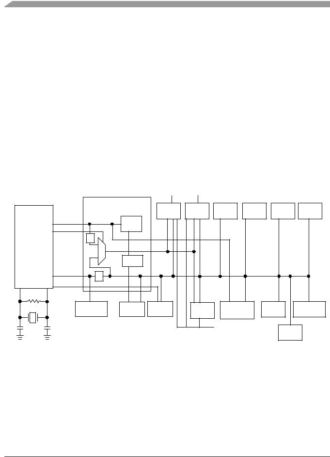
Chapter 1 Introduction
Table 1 lists the functional versions of the on-chip modules.
Table 1. Versions of On-Chip Modules
Module |
|
Version |
|
|
|
Cyclic Redundancy Check Generator |
(CRC) |
1 |
|
|
|
Analog-to-Digital Converter |
(ADC) |
1 |
|
|
|
Internal Clock Generator |
(ICG) |
4 |
|
|
|
Inter-Integrated Circuit |
(IIC) |
2 |
|
|
|
Keyboard Interrupt |
(KBI) |
1 |
|
|
|
Serial Communications Interface |
(SCI) |
4 |
|
|
|
Serial Peripheral Interface |
(SPI) |
3 |
|
|
|
Timer Pulse-Width Modulator |
(TPM) |
3 |
|
|
|
Central Processing Unit |
(CPU) |
2 |
|
|
|
Debug Module |
(DBG) |
2 |
|
|
|
1.3System Clock Distribution
|
|
|
|
TPM1CLK |
TPM2CLK |
|
|
|
|
|
|
SYSTEM |
|
TPM1 |
TPM2 |
IIC1 |
SCI1 |
SCI2 |
SPI1 |
|
|
CONTROL |
|
||||||
|
ICGERCLK |
LOGIC |
|
|
|
|
|
|
|
|
|
RTI |
|
|
|
|
|
|
|
|
FFE |
|
|
|
|
|
|
|
|
|
|
|
|
|
|
|
|
|
|
|
|
2 |
|
|
|
|
|
|
|
ICG |
|
XCLK** |
|
|
|
|
|
|
|
|
|
|
1 kHz |
|
|
|
|
|
|
|
ICGOUT |
2 |
BUSCLK |
|
|
|
|
|
|
|
|
|
|
|
|
|
|
|
|
|
ICGLCLK* |
|
|
|
|
|
|
|
|
|
|
CPU |
COP |
BDC |
TPM3 |
ADC1 |
|
RAM |
FLASH |
|
|
|
|
|
|
TPMCLK |
|
CRC |
|
|
|
|
|
|
|
|
|
|
*ICGLCLK is the alternate BDC clock source for the MC9S08AC60 Series.
**Fixed frequency clock.
Figure 1-2. System Clock Distribution Diagram
Some of the modules inside the MCU have clock source choices. Figure 1-2 shows a simplified clock connection diagram. The ICG supplies the clock sources:
•ICGOUT is an output of the ICG module. It is one of the following:
— The external crystal oscillator
MC9S08AC60 Series Data Sheet, Rev. 2
22 |
Freescale Semiconductor |

Chapter 1 Introduction
—An external clock source
—The output of the digitally-controlled oscillator (DCO) in the frequency-locked loop sub-module
—Control bits inside the ICG determine which source is connected.
•FFE is a control signal generated inside the ICG. If the frequency of ICGOUT > 4 × the frequency of ICGERCLK, this signal is a logic 1 and the fixed-frequency clock will be ICGERCLK/2. Otherwise the fixed-frequency clock will be BUSCLK.
•ICGLCLK — Development tools can select this internal self-clocked source (~ 8 MHz) to speed up BDC communications in systems where the bus clock is slow.
•ICGERCLK — External reference clock can be selected as the real-time interrupt clock source. Can also be used as the ALTCLK input to the ADC module.
MC9S08AC60 Series Data Sheet, Rev. 2
Freescale Semiconductor |
23 |

Chapter 1 Introduction
MC9S08AC60 Series Data Sheet, Rev. 2
24 |
Freescale Semiconductor |

Chapter 2
Pins and Connections
2.1Introduction
This chapter describes signals that connect to package pins. It includes a pinout diagram, a table of signal properties, and detailed discussion of signals.
2.2Device Pin Assignment
Figure 2-1. shows the 64-pin package assignments for the MC9S08AC60 Series devices.
MC9S08AC60 Series Data Sheet, Rev. 2
Freescale Semiconductor |
25 |

Chapter 2 Pins and Connections
|
|
|
|
|
|
PTC5/RxD2 |
|
PTC3/TxD2 |
PTC2/MCLK |
PTC1/SDA1 |
PTC0/SCL1 |
V |
PTG6/EXTAL |
|
PTG5/XTAL |
|
BKGD/MS |
V |
V |
PTD7/KBI1P7/AD1P15 |
PTD6/TPM1CLK/AD1P14 |
PTD5/AD1P13 |
PTD4/TPM2CLK/AD1P12 |
PTG4/KBI1P4 |
|||||||||||||
|
|
|
|
|
|
|
|
|
|
|
|
|
|
|
|
SS |
|
|
|
|
|
|
REFL |
REFH |
|
|
|
|
|
|
|
|
|
|
|||
|
|
|
|
|
|
64 |
|
|
|
|
|
|
|
|
|
|
|
|
|
|
|
|
|
|
|
|
|
|
|
|
|
|
|
|
|
49 |
|
|
PTC4 |
|
|
|
63 |
|
62 |
|
61 |
|
60 |
|
59 |
|
58 |
57 |
56 |
|
55 |
|
54 |
|
53 |
|
52 |
|
51 |
|
50 |
|
|
|
|||||
|
1 |
|
|
|
|
|
|
|
|
|
|
|
|
|
|
|
|
|
|
|
|
|
|
|
|
|
|
|
|
|
|
|
|
|
|||
IRQ/TPMCLK |
|
2 |
|
|
|
|
|
|
|
|
|
|
|
|
|
|
|
|
|
|
|
|
|
|
|
|
|
|
|
|
|
|
47 |
||||
|
|
|
|
|
|
|
|
|
|
|
|
|
|
|
|
|
|
|
|
|
|
|
|
|
|
|
|
|
|
|
|||||||
|
|
|
|
|
|
|
|
|
|
|
|
|
|
|
|
|
|
|
|
|
|
|
|
|
|
|
|
|
|
|
|
|
|
|
|
46 |
|
|
RESET |
|
3 |
|
|
|
|
|
|
|
|
|
|
|
|
|
|
|
|
|
|
|
|
|
|
|
|
|
|
|
|
|
|
||||
PTF0/TPM1CH2 |
|
4 |
|
|
|
|
|
|
|
|
|
|
|
|
|
|
|
|
|
|
|
|
|
|
|
|
|
|
|
|
|
|
45 |
||||
|
|
|
|
|
|
|
|
|
|
|
|
|
|
|
|
|
|
|
|
|
|
|
|
|
|
|
|
|
|
|
|||||||
PTF1/TPM1CH3 |
|
5 |
|
|
|
|
|
|
|
|
|
|
|
|
|
|
|
|
|
|
|
|
|
|
|
|
|
|
|
|
|
|
44 |
||||
|
|
|
|
|
|
|
|
|
|
|
|
|
|
|
|
|
|
|
|
|
|
|
|
|
|
|
|
|
|
|
|||||||
PTF2/TPM1CH4 |
|
6 |
|
|
|
|
|
|
|
|
|
|
|
|
|
|
|
|
|
|
|
|
|
|
|
|
|
|
|
|
|
|
43 |
||||
|
|
|
|
|
|
|
|
|
|
|
|
|
|
|
|
|
|
|
|
|
|
|
|
|
|
|
|
|
|
|
|||||||
PTF3/TPM1CH5 |
|
7 |
|
|
|
|
|
|
|
|
|
|
|
|
|
|
|
|
|
|
|
|
|
|
|
|
|
|
|
|
|
|
42 |
||||
|
|
|
|
|
|
|
|
|
|
|
|
|
|
|
|
|
|
|
|
|
|
|
|
|
|
|
|
|
|
|
|||||||
PTF4/TPM2CH0 |
|
8 |
|
|
|
|
|
|
|
|
|
|
|
|
64-Pin QFP |
|
|
|
|
|
|
|
|
|
|
41 |
|||||||||||
|
|
|
|
|
|
|
|
|
|
|
|
|
|
|
|
|
|
|
|
|
|
|
|||||||||||||||
|
|
|
|
|
|
|
|
|
|
|
|
|
|
|
|
|
|
|
|
|
|
|
|
|
|
|
|
|
|
||||||||
|
PTC6 |
|
9 |
|
|
|
|
|
|
|
|
|
|
|
|
64-Pin LQFP |
|
|
|
|
|
|
|
|
|
|
40 |
||||||||||
|
PTF7 |
|
10 |
|
|
|
|
|
|
|
|
|
|
|
|
|
|
|
|
|
|
|
|
|
|
|
|
|
|
|
|
|
|
39 |
|||
|
|
|
|
|
|
|
|
|
|
|
|
|
|
|
|
|
|
|
|
|
|
|
|
|
|
|
|
|
|
|
|
||||||
PTF5/TPM2CH1 |
|
11 |
|
|
|
|
|
|
|
|
|
|
|
|
|
|
|
|
|
|
|
|
|
|
|
|
|
|
|
|
|
|
38 |
||||
|
|
|
|
|
|
|
|
|
|
|
|
|
|
|
|
|
|
|
|
|
|
|
|
|
|
|
|
|
|
|
|||||||
|
PTF6 |
|
12 |
|
|
|
|
|
|
|
|
|
|
|
|
|
|
|
|
|
|
|
|
|
|
|
|
|
|
|
|
|
|
37 |
|||
|
|
|
|
|
|
|
|
|
|
|
|
|
|
|
|
|
|
|
|
|
|
|
|
|
|
|
|
|
|
|
|
||||||
PTE0/TxD1 |
|
13 |
|
|
|
|
|
|
|
|
|
|
|
|
|
|
|
|
|
|
|
|
|
|
|
|
|
|
|
|
|
|
36 |
||||
|
|
|
|
|
|
|
|
|
|
|
|
|
|
|
|
|
|
|
|
|
|
|
|
|
|
|
|
|
|
|
|||||||
|
|
|
|
|
|
|
|
|
|
|
|
|
|
|
|
|
|
|
|
|
|
|
|
|
|
|
|
|
|
|
|||||||
PTE1/RxD1 |
|
14 |
|
|
|
|
|
|
|
|
|
|
|
|
|
|
|
|
|
|
|
|
|
|
|
|
|
|
|
|
|
|
35 |
||||
|
|
|
|
|
|
|
|
|
|
|
|
|
|
|
|
|
|
|
|
|
|
|
|
|
|
|
|
|
|
|
|||||||
|
|
|
|
|
|
|
|
|
|
|
|
|
|
|
|
|
|
|
|
|
|
|
|
|
|
|
|
|
|
|
|||||||
PTE2/TPM1CH0 |
|
15 |
|
|
|
|
|
|
|
|
|
|
|
|
|
|
|
|
|
|
|
|
|
|
|
|
|
|
|
|
|
|
34 |
||||
|
|
|
|
|
|
|
|
|
|
|
|
|
|
|
|
|
|
|
|
|
|
|
|
|
|
|
|
|
|
|
|||||||
|
|
|
|
|
|
|
|
|
|
|
|
|
|
|
|
|
|
|
|
|
|
|
|
|
|
|
|
|
|
|
|||||||
PTE3/TPM1CH1 |
|
|
|
|
|
|
|
|
|
|
|
|
|
|
|
|
|
|
|
|
|
|
|
|
|
|
|
|
|
|
|
|
|
|
|
||
|
16 |
|
|
18 |
|
19 |
|
20 |
|
21 |
|
22 |
|
23 |
24 |
25 |
|
26 |
|
27 |
|
28 |
|
29 |
|
30 |
|
31 |
|
|
|
||||||
|
|
|
|
|
|
|
|
|
|
|
|
|
|
|
|
|
|
|
|
|
|||||||||||||||||
|
|
|
|
|
|
17 |
|
|
|
|
|
|
|
|
|
|
|
|
|
|
|
|
|
|
|
|
|
|
|
|
|
|
|
|
|
32 |
|
|
|
|
|
|
|
PTE4/SS1 |
|
PTE5/MISO1 |
PTE6/MOSI1 |
PTE7/SPSCK1 |
V |
V |
PTG0/KBI1P0 |
|
PTG1/KBI1P1 |
|
PTG2/KBI1P2 |
PTA0 |
PTA1 |
PTA2 |
PTA3 |
PTA4 |
PTA5 |
PTA6 |
|||||||||||||
|
|
|
|
|
|
|
|
|
|
|
|
|
|
SS |
DD |
|
|
|
|
|
|
|
|
|
|
|
|
|
|
|
|
|
|
|
|
||
48 PTG3/KBI1P3
PTD3/KBI1P6/AD1P11
PTD2/KBI1P5/AD1P10
VSSAD
VDDAD
PTD1/AD1P9
PTD0/AD1P8
PTB7/AD1P7
PTB6/AD1P6
PTB5/AD1P5
PTB4/AD1P4
PTB3/AD1P3
PTB2/AD1P2
PTB1/TPM3CH1/AD1P1
PTB0/TPM3CH0/AD1P0
33 PTA7
Figure 2-1. MC9S08AC60 Series in 64-Pin QFP or LQFP Package
MC9S08AC60 Series Data Sheet, Rev. 2
26 |
Freescale Semiconductor |

Chapter 2 Pins and Connections
Figure 2-2 shows the 48-pin QFN pin assignments for the MC9S08AC60 Series device.
|
PTC5/RxD2 |
PTC3/TxD2 |
PTC2/MCLK |
PTC1/SDA1 |
PTC0/SCL1 |
SS |
PTG6/EXTAL |
PTG5/XTAL |
BKGD/MS |
REFL |
REFH |
PTG4/KB1IP4 |
|
|
V |
V |
V |
|
|||||||||
PTC4 |
48 |
47 |
46 |
45 |
44 |
43 |
42 |
41 |
40 |
39 |
38 |
37 |
PTG3/KBI1P3 |
1 |
|
|
|
|
|
|
|
|
|
|
36 |
||
IRQ/TPMCLK |
2 |
|
|
|
|
|
|
|
|
|
|
35 |
PTD3/KBI1P6/AD1P11 |
RESET |
3 |
|
|
|
|
|
|
|
|
|
|
34 |
PTD2/KBI1P5/AD1P10 |
PTF0/TPM1CH2 |
4 |
|
|
|
|
|
|
|
|
|
|
33 |
VSSAD |
PTF1/TPM1CH3 |
5 |
|
|
|
|
|
|
|
|
|
|
32 |
VDDAD |
PTF4/TPM2CH0 |
6 |
|
|
|
48-Pin QFN |
|
|
|
31 |
PTD1/AD1P9 |
|||
PTF5/TPM2CH1 |
7 |
|
|
|
|
|
|
|
|
|
|
30 |
PTD0/AD1P8 |
PTF6 |
8 |
|
|
|
|
|
|
|
|
|
|
29 |
PTB3/AD1P3 |
PTE0/TxD1 |
9 |
|
|
|
|
|
|
|
|
|
|
28 |
PTB2/AD1P2 |
PTE1/RxD1 |
10 |
|
|
|
|
|
|
|
|
|
|
27 |
PTB1/TPM3CH1/AD1P1 |
PTE2/TPM1CH0 |
11 |
|
|
|
|
|
|
|
|
|
|
26 |
PTB0/TPM3CH0/AD1P0 |
PTE3/TPM1CH1 |
12 |
|
|
|
|
|
|
|
|
|
|
25 |
PTA7 |
|
13 |
14 |
15 |
16 |
17 |
18 |
19 |
20 |
21 |
22 |
23 |
24 |
|
|
PTE4/SS1 |
PTE5/MISO1 |
PTE6/MOSI1 |
PTE7/SPSCK1 |
SS |
DD |
PTG0/KBI1P0 |
PTG1/KBI1P1 |
PTG2/KBI1P2 |
PTA0 |
PTA1 |
PTA2 |
|
|
V |
V |
|
||||||||||
Figure 2-2. MC9S08AC60 Series in 48-Pin QFN Package
MC9S08AC60 Series Data Sheet, Rev. 2
Freescale Semiconductor |
27 |

Chapter 2 Pins and Connections
Figure 2-3. shows the 44-pin LQFP pin assignments for the MC9S08AC60 Series device.
|
|
|
|
|
PTC5/RxD2 |
|
PTC3/TxD2 |
PTC2/MCLK |
PTC1/SDA1 |
|
PTC0/SCL1 |
SS |
PTG6/EXTAL |
PTG5/XTAL |
|
BKGD/MS |
REFL |
||||||
|
|
|
|
|
|
|
V |
|
V |
||||||||||||||
|
|
|
|
|
44 |
|
|
|
|
|
|
|
|
|
|
|
|
|
|
|
|
|
|
|
PTC4 |
|
|
|
43 |
|
42 |
|
41 |
40 |
|
39 |
|
38 |
|
37 |
36 |
|
35 |
||||
|
1 |
|
|
|
|
|
|
|
|
|
|
|
|
|
|
|
|
|
|
|
|
||
IRQ/TPMCLK |
|
2 |
|
|
|
|
|
|
|
|
|
|
|
|
|
|
|
|
|
|
|
||
|
|
|
|
|
|
|
|
|
|
|
|
|
|
|
|
|
|
|
|
||||
|
|
|
|
|
|
|
|
|
|
|
|
|
|
|
|
|
|
|
|
|
|
|
|
|
RESET |
|
3 |
|
|
|
|
|
|
|
|
|
|
|
|
|
|
|
|
|
|
|
|
PTF0/TPM1CH2 |
|
4 |
|
|
|
|
|
|
|
|
|
|
|
|
|
|
|
|
|
|
|
||
|
|
|
|
|
|
|
|
|
|
|
|
|
|
|
|
|
|
|
|
||||
PTF1/TPM1CH3 |
|
5 |
|
|
|
|
|
|
|
|
|
|
|
|
|
|
|
|
|
|
|
||
|
|
|
|
|
|
|
|
|
|
|
|
|
|
|
|
|
|
|
|
||||
PTF4/TPM2CH0 |
|
6 |
|
|
|
|
|
|
|
44-Pin LQFP |
|
|
|
|
|
||||||||
|
|
|
|
|
|
|
|
|
|
|
|
|
|||||||||||
|
|
|
|
|
|
|
|
|
|
|
|
|
|
|
|
|
|
|
|
||||
PTF5/TPM2CH1 |
|
7 |
|
|
|
|
|
|
|
|
|
|
|
|
|
|
|
|
|
|
|
||
|
|
|
|
|
|
|
|
|
|
|
|
|
|
|
|
|
|
|
|
||||
PTE0/TxD1 |
|
8 |
|
|
|
|
|
|
|
|
|
|
|
|
|
|
|
|
|
|
|
||
|
|
|
|
|
|
|
|
|
|
|
|
|
|
|
|
|
|
|
|
||||
PTE1/RxD1 |
|
9 |
|
|
|
|
|
|
|
|
|
|
|
|
|
|
|
|
|
|
|
||
|
|
|
|
|
|
|
|
|
|
|
|
|
|
|
|
|
|
|
|
||||
|
|
|
|
|
|
|
|
|
|
|
|
|
|
|
|
|
|
|
|
||||
PTE2/TPM1CH0 |
|
10 |
|
|
|
|
|
|
|
|
|
|
|
|
|
|
|
|
|
|
|||
|
|
|
|
|
|
|
|
|
|
|
|
|
|
|
|
|
|
|
|||||
|
|
|
|
|
|
|
|
|
|
|
|
|
|
|
|
|
|
|
|||||
PTE3/TPM1CH1 |
|
|
|
|
|
|
|
|
|
|
|
|
|
|
|
|
|
|
|
|
|
||
|
|
|
|
|
|
|
|
|
|
|
|
|
|
|
|
|
|
|
|
|
|||
11 |
|
|
|
|
|
|
|
|
|
|
|
|
|
|
|
|
|
|
|
|
|||
|
|
|
|
|
|
13 |
|
14 |
|
15 |
16 |
|
17 |
|
18 |
|
19 |
20 |
|
21 |
|||
|
|
|
|
|
|
|
|
|
|
|
|
|
|
|
|
|
|
|
|
|
|
|
|
|
|
|
|
|
12 |
|
|
|
|
|
|
|
|
|
|
|
|
|
|
|
|
|
|
|
|
|
|
|
PTE4/SS1 |
|
PTE5/MISO1 |
PTE6/MOSI1 |
PTE7/SPSCK1 |
|
SS |
DD |
PTG0/KBI1P0 |
PTG1/KBI1P1 |
|
PTG2/KBI1P2 |
PTA0 |
||||||
|
|
|
|
|
|
|
V |
V |
|
||||||||||||||
|
|
|
|
|
|
|
|
|
|
|
|
||||||||||||
VREFH
34
33 PTG3/KBI1P3
32 PTD3/KBI1P6/AD1P11
31 PTD2/KBI1P5/AD1P10
30 VSSAD
29 VDDAD
28 PTD1/AD1P9
27  PTD0/AD1P8
26 PTB3/AD1P3
25  PTB2/AD1P2
24 PTB1/TPM3CH1/AD1P1
23 PTB0/TPM3CH0/AD1P0
22
PTA1
Figure 2-3. MC9S08AC60 Series in 44-Pin LQFP Package
MC9S08AC60 Series Data Sheet, Rev. 2
28 |
Freescale Semiconductor |

Chapter 2 Pins and Connections
Figure 2-4. shows the 32-pin LQFP pin assignments for the MC9S08AC60 Series device.
|
|
|
|
|
PTC1/SDA1 |
|
PTC0/SCL1 |
V |
PTG6/EXTAL |
PTG5/XTAL |
BKGD/MS |
V |
|
V |
|
|||||||
|
|
|
|
|
|
|
|
|
SS |
|
|
|
|
|
|
REFL |
|
REFH |
|
|||
|
|
|
|
32 |
|
|
|
|
|
|
|
|
|
|
|
|
|
|
|
|
|
|
|
|
|
|
|
|
31 |
|
30 |
|
29 |
|
28 |
|
27 |
|
26 |
25 |
|
|
|
||
IRQ/TPMCLK |
1 |
2 |
|
|
|
|
|
|
|
|
|
|
|
|
|
|
|
|
24 |
PTD3/KBI1P6/AD1P11 |
||
|
|
|
|
|
|
|
|
|
|
|
|
|
|
|
|
|
|
|
|
|||
|
|
|
|
|
|
|
|
|
|
|
|
|
|
|
|
|
|
|
|
|
|
|
|
|
|
|
|
|
|
|
|
|
|
|
|
|
|
|
|
|
|
|
|
|
|
|
RESET |
|
|
|
|
|
|
|
|
|
|
|
|
|
|
|
23 |
|
PTD2/KBI1P5/AD1P10 |
|||
PTF4/TPM2CH0 |
|
3 |
|
|
|
|
|
|
|
|
|
|
|
|
|
22 |
|
VSSAD |
||||
|
|
|
|
|
|
|
|
|
|
|
|
|
|
|
||||||||
|
|
|
|
|
|
|
|
|
|
|
|
|
|
|
||||||||
|
|
|
|
|
|
|
|
|
|
|
|
|
|
|
||||||||
PTF5/TPM2CH1 |
|
4 |
|
|
|
|
|
|
|
|
|
|
|
|
|
|
||||||
|
|
|
|
|
32-Pin LQFP |
|
21 |
|
VDDAD |
|||||||||||||
|
|
|
|
|
|
|
||||||||||||||||
PTE0/TxD1 |
|
5 |
|
|
|
|
|
|
||||||||||||||
|
|
|
|
|
|
20 |
|
|||||||||||||||
|
|
|
|
|
|
|
|
|
|
|
|
|
|
|
PTB3/AD1P3 |
|||||||
|
|
|
|
|
|
|
|
|
|
|
|
|
|
|
||||||||
PTE1/RxD1 |
|
6 |
|
|
|
|
|
|
|
|
|
|
|
|
|
19 |
|
PTB2/AD1P2 |
||||
|
|
|
|
|
|
|
|
|
|
|
|
|
|
|
||||||||
|
|
|
|
|
|
|
|
|
|
|
|
|
|
|
||||||||
|
|
|
|
|
|
|
|
|
|
|
|
|
|
|
||||||||
PTE2/TPM1CH0 |
|
7 |
|
|
|
|
|
|
|
|
|
|
|
|
|
18 |
|
PTB1/TPM3CH1/AD1P1 |
||||
|
|
|
|
|
|
|
|
|
|
|
|
|
|
|
||||||||
|
|
|
|
|
|
|
|
|
|
|
|
|
|
|
||||||||
|
|
|
|
|
|
|
|
|
|
|
|
|
|
|
||||||||
PTE3/TPM1CH1 |
|
8 |
|
|
|
|
|
|
|
|
|
|
|
|
|
|
||||||
|
|
|
|
|
|
|
|
|
|
|
|
|
|
17 |
|
PTB0/TPM3CH0/AD1P0 |
||||||
|
|
|
|
|
|
|
|
|
|
|
|
|
|
|
||||||||
|
|
|
|
|
|
|
|
|
|
|
|
|
|
|
||||||||
|
|
|
|
|
|
|
|
|
|
|
|
|
|
|
||||||||
|
|
|
|
|
|
10 |
|
11 |
|
12 |
|
13 |
|
14 |
|
15 |
16 |
|
|
|
||
|
|
|
|
|
|
|
|
|
|
|
|
|
||||||||||
|
|
|
|
9 |
|
|
|
|
|
|
|
|
|
|
|
|
|
|
|
|
|
|
|
|
|
|
|
|
|
|
|
|
|
|
|
|
|
|
|
|
|
|
|
|
|
|
|
|
|
|
PTE4/SS1 |
|
PTE5/MISO1 |
PTE6/MOSI1 |
PTE7/SPSCK1 |
SS |
DD |
PTG0/KBI1P0 |
|
PTG1/KBI1P1 |
|
|||||||
|
|
|
|
|
|
|
|
|||||||||||||||
|
|
|
|
|
|
V |
V |
|
|
|||||||||||||
|
|
|
|
|
|
|
|
|
|
|
|
|||||||||||
Figure 2-4. MC9S08AC60 Series in 32-Pin LQFP Package
2.3Recommended System Connections
Figure 2-5 shows pin connections that are common to almost all MC9S08AC60 Series application systems.
MC9S08AC60 Series Data Sheet, Rev. 2
Freescale Semiconductor |
29 |
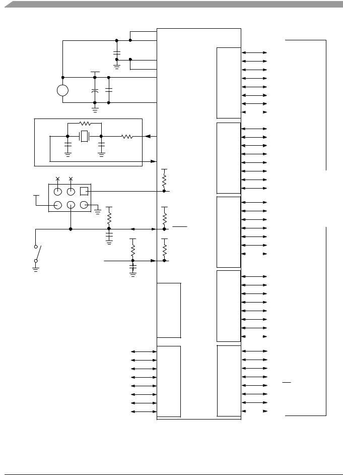
Chapter 2 Pins and Connections |
|
|
|
|
|
|
|
|
|
VREFH |
MC9S08AC60 |
|
|
|
CBYAD |
VDDAD |
|
|
|
|
0.1 μF |
|
|
SYSTEM |
VDD |
|
|
VSSAD |
|
|
|
VREFL |
|
||
POWER |
|
|
|
|
|
|
|
|
VDD |
|
|
+ |
|
|
|
|
|
+ |
|
CBY |
|
|
|
5 V |
|
|
|
||
CBLK |
|
|
|
||
|
10 μF |
|
0.1 μF |
|
|
|
|
|
|
VSS (x2) |
|
NOTE 1 |
RF |
|
|
|
|
|
|
RS |
|
|
|
|
|
|
XTAL |
|
|
|
|
|
|
|
|
C1 |
X1 |
C2 |
|
NOTE 2 |
|
|
|
|
|||
|
|
|
|
|
|
|
|
|
|
EXTAL |
|
|
|
|
|
NOTE 2 |
|
BACKGROUND HEADER |
|
|
|
|
|
VDD |
1 |
|
|
|
|
|
|
|
BKGD/MS |
||
|
|
VDD |
|
|
|
|
|
|
4.7 kΩ–10 kΩ |
|
|
|
|
|
0.1 μF VDD |
RESET |
|
|
|
|
|
|
|
OPTIONAL |
ASYNCHRONOUS |
4.7 kΩ– |
|
|
|
MANUAL |
10 kΩ |
|
|
||
RESET |
INTERRUPT |
|
|
IRQ |
|
|
INPUT |
|
0.1 μF |
NOTE 1 |
|
PTG0/KBI1P0 

PTG1/KBI1P1 

PTG2/KBI1P2 
 PORT
PORT
PTG3/KBI1P3 
 G
G
PTG4/KBI1P4 

PTG5/XTAL 

PTG6/EXTAL 

NOTES: |
|
|
|
1. Not required if |
PTF0/TPM1CH2 |
|
|
using the internal |
|
||
PTF1/TPM1CH3 |
|
||
clock option. |
|
||
2. These are the |
PTF2/TPM1CH4 |
|
|
same pins as |
PTF3/TPM1CH5 |
PORT |
|
PTG5 and PTG6 |
|||
PTF4/TPM2CH0 |
F |
||
3. RC filters on |
|||
PTF5/TPM2CH1 |
|
||
RESET and IRQ |
|
||
are recommended |
PTF6 |
|
|
for EMC-sensitive |
PTF7 |
|
|
applications. |
|
|
PORT
A
PORT
B
PORT
C
PORT
D
PORT
E
PTA0 |
|
|
PTA1 |
|
|
PTA2 |
|
|
PTA3 |
|
|
PTA4 |
|
|
PTA5 |
|
|
PTA6 |
|
|
PTA7 |
|
|
PTB0/AD1P0 |
|
|
PTB1/AD1P1 |
|
|
PTB2/AD1P2 |
|
|
PTB3/AD1P3 |
|
|
PTB4/AD1P4 |
|
|
PTB5/AD1P5 |
|
|
PTB6/AD1P6 |
I/O AND |
|
PTB7/AD1P7 |
PERIPHERAL |
|
PTC0/SCL1 |
INTERFACE TO |
|
PTC1/SDA1 |
APPLICATION |
|
PTC2/MCLK |
SYSTEM |
|
PTC3/TxD2 |
||
|
||
PTC4 |
|
|
PTC5/RxD2 |
|
|
PTC6 |
|
|
PTD0/AD1P8 |
|
|
PTD1/AD1P9 |
|
|
PTD2/KBI1P5/AD1P10 |
||
PTD3/KBI1P6/AD1P11 |
||
PTD4/TPM2CLK/AD1P12 |
||
PTD5/AD1P13 |
|
|
PTD6/TPM1CLK/AD1P14 |
||
PTD7/KBI1P7/AD1P15 |
||
PTE0/TxD1 |
|
|
PTE1/RxD1 |
|
|
PTE2/TPM1CH0 |
|
|
PTE3/TPM1CH1 |
|
|
PTE4/SS1 |
|
|
PTE5/MISO1 |
|
|
PTE6/MOSI1 |
|
|
PTE7/SPSCK1 |
|
|
Figure 2-5. Basic System Connections
MC9S08AC60 Series Data Sheet, Rev. 2
30 |
Freescale Semiconductor |
Loading...