

Page 1
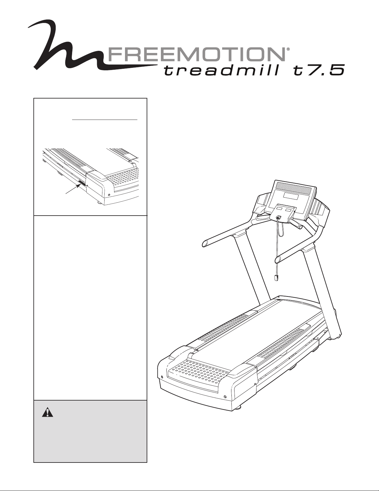
Model No. VMTL83607.5
Serial No.
Write the serial number in the space
above for reference.
Serial
Number
Decal
QUESTIONS?
If you have questions, or if parts are
damaged or missing, PLEASE CON-
TACT THE STORE WHERE YOU
PURCHASED THIS PRODUCT.
If you are unable to contact the
store, please see HOW TO
CONTACT CUSTOMER CARE on
the back cover of this manual.
USERʼS MANUAL
CAUTION
Read all precautions and instructions in this manual before
using this equipment. Keep this
manual for future reference.
www.freemotionfitness.com
Page 2
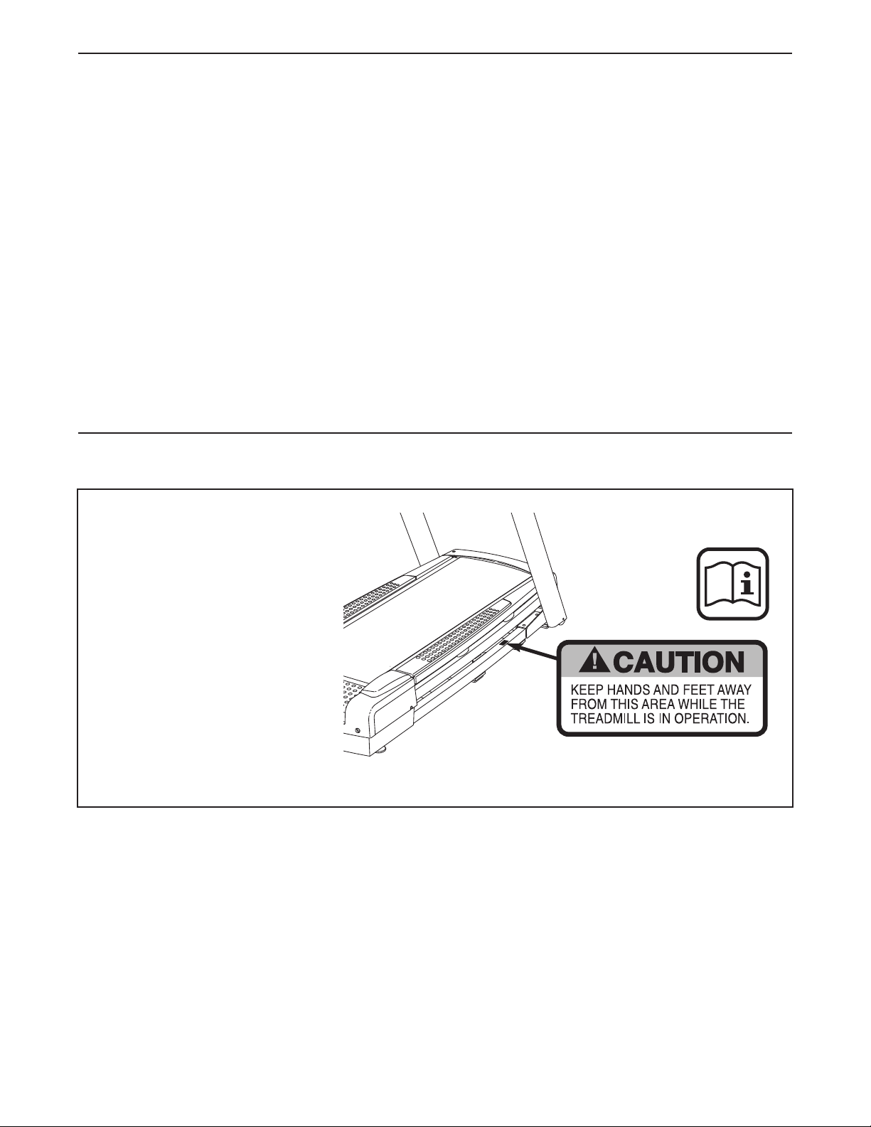
TABLE OF CONTENTS
WARNING DECAL PLACEMENT . . . . . . . . . . . . . . . . . . . . . . . . . . . . . . . . . . . . . . . . . . . . . . . . . . . . . . . . . . . . . .2
IMPORTANT PRECAUTIONS . . . . . . . . . . . . . . . . . . . . . . . . . . . . . . . . . . . . . . . . . . . . . . . . . . . . . . . . . . . . . . . . .3
EFORE YOU BEGIN . . . . . . . . . . . . . . . . . . . . . . . . . . . . . . . . . . . . . . . . . . . . . . . . . . . . . . . . . . . . . . . . . . . . . . .5
B
ASSEMBLY . . . . . . . . . . . . . . . . . . . . . . . . . . . . . . . . . . . . . . . . . . . . . . . . . . . . . . . . . . . . . . . . . . . . . . . . . . . . . . .6
HOW TO MOVE THE TREADMILL . . . . . . . . . . . . . . . . . . . . . . . . . . . . . . . . . . . . . . . . . . . . . . . . . . . . . . . . . . . .12
HOW TO UPGRADE THE CONSOLE . . . . . . . . . . . . . . . . . . . . . . . . . . . . . . . . . . . . . . . . . . . . . . . . . . . . . . . . . .13
OPERATION AND ADJUSTMENT . . . . . . . . . . . . . . . . . . . . . . . . . . . . . . . . . . . . . . . . . . . . . . . . . . . . . . . . . . . .14
PREVENTIVE MAINTENANCE . . . . . . . . . . . . . . . . . . . . . . . . . . . . . . . . . . . . . . . . . . . . . . . . . . . . . . . . . . . . . . .26
SIX-MONTH PREVENTIVE MAINTENANCE RECORD . . . . . . . . . . . . . . . . . . . . . . . . . . . . . . . . . . . . . . . . . . . .29
TROUBLESHOOTING . . . . . . . . . . . . . . . . . . . . . . . . . . . . . . . . . . . . . . . . . . . . . . . . . . . . . . . . . . . . . . . . . . . . . .30
EXERCISE GUIDELINES . . . . . . . . . . . . . . . . . . . . . . . . . . . . . . . . . . . . . . . . . . . . . . . . . . . . . . . . . . . . . . . . . . .32
PART LIST . . . . . . . . . . . . . . . . . . . . . . . . . . . . . . . . . . . . . . . . . . . . . . . . . . . . . . . . . . . . . . . . . . . . . . . . . . . . . . .33
EXPLODED DRAWING . . . . . . . . . . . . . . . . . . . . . . . . . . . . . . . . . . . . . . . . . . . . . . . . . . . . . . . . . . . . . . . . . . . . .35
HOW TO CONTACT CUSTOMER CARE . . . . . . . . . . . . . . . . . . . . . . . . . . . . . . . . . . . . . . . . . . . . . . . .Back Cover
LIMITED WARRANTY . . . . . . . . . . . . . . . . . . . . . . . . . . . . . . . . . . . . . . . . . . . . . . . . . . . . . . . . . . . . . . .Back Cover
WARNING DECAL PLACEMENT
The decal shown here has been
applied in the indicated locations. If the decal is missing or
illegible, see the back cover
of this manual and request a
free replacement decal. Apply
the decal in the location
shown. Note: The decal may
not be shown at actual size.
Note: There is one decal on
each side.
FREEMOTION is a registered trademark of ICON IP, Inc.
2
Page 3

IMPORTANT PRECAUTIONS
WARNING: To reduce the risk of serious injury, read all important precautions and in-
tructions in this manual and all warnings on your treadmill before using your treadmill. FreeMotion
s
Fitness assumes no responsibility for personal injury or property damage sustained by or through
the use of this product.
1. Before beginning any exercise program, consult your physician. This is especially important for persons over age 35 or persons with
pre-existing health problems.
2. It is the responsibility of the owner to ensure
that all users of the treadmill are adequately
informed of all warnings and precautions.
3. Use the treadmill only as described in this
manual.
4. Keep the treadmill indoors, away from moisture and dust. Do not place the treadmill in a
garage or covered patio, or near water.
5. Place the treadmill on a level surface, with at
least 8 ft. (2.4 m) of clearance behind it and 2
ft. (0.6 m) on each side. Do not place the
treadmill on any surface that blocks air openings. To protect the floor or carpet from damage, place a mat under the treadmill.
6. Do not operate the treadmill where aerosol
products are used or where oxygen is being
administered.
7. Do not operate the treadmill until it is properly assembled (see ASSEMBLY on page 6).
8. Inspect and properly tighten all parts of the
treadmill regularly.
9. Keep children under age 12 and pets away
from the treadmill at all times.
10. The treadmill should not be used by persons
weighing more than 350 lbs. (159 kg). Do not
allow more than one person on the treadmill
at a time.
11. Wear appropriate exercise clothes when
using the treadmill. Do not wear loose
clothes that could become caught in the
treadmill. Athletic support clothes are recommended for both men and women. Always
wear athletic shoes. Never use the treadmill
with bare feet, wearing only stockings, or in
sandals.
12. When connecting the power cord (see page
14), plug the power cord into a surge suppressor (not included) and plug the surge suppressor into a grounded circuit capable of
carrying 15 or more amps. No other appliance
should be on the same circuit. Do not use an
extension cord.
13. Use only a single-outlet surge suppressor that
meets all of the specifications described on
page 14. To purchase a surge suppressor,
please see the back cover of this manual and
order part number 146148, or see your local
electronics store.
14. Failure to use a properly functioning surge
suppressor could result in damage to the control system of the treadmill. If the control system is damaged, the walking belt may slow,
accelerate, or stop unexpectedly, which may
result in a fall and serious injury.
15. Keep the power cord and the surge suppressor away from heated surfaces.
16. Never move the walking belt while the power
is turned off. Do not operate the treadmill if
the power cord or plug is damaged or if the
treadmill is not working properly. (See TROUBLESHOOTING on page 30 if the treadmill is
not working properly.)
17. Read, understand, and test the emergency
stop procedure before using the treadmill (see
page 16).
18. Never start the treadmill while you are standing on the walking belt. Always hold the
handrails while using the treadmill.
19. The treadmill is capable of high speeds.
Adjust the speed in small increments to
avoid sudden jumps in speed.
3
Page 4

20. Never leave the treadmill unattended while it is
running. Always remove the key, unplug the
power cord, and press the power switch into
he off position when the treadmill is not in
t
use. (See the drawing on page 5 for the location of the power switch.)
21. Do not change the incline of the treadmill by
placing objects under it.
22. Never insert or drop any object into any
opening on the treadmill.
23. Make sure to perform all maintenance procedures outlined in this manual. Failure to do
so will void the warranty and may result in
damage to the treadmill.
SAVE THESE INSTRUCTIONS
DANGER: Always unplug the power
24.
cord immediately after use, before cleaning
the treadmill, and before performing the
maintenance and adjustment procedures de-
cribed in this manual. Servicing other than
s
the procedures in this manual should be performed by an authorized service representative only.
25. Over exercising may result in serious injury
or death. If you feel faint or if you experience
pain while exercising, stop immediately and
cool down.
4
Page 5
BEFORE YOU BEGIN
Congratulations for selecting the revolutionary
FREEMOTION®T7.5 treadmill. The T7.5 treadmill offers an impressive array of features designed to help
ou achieve your fitness goals in the convenience and
y
privacy of your home.
For your benefit, read this manual carefully before
using the treadmill. If you have questions after read-
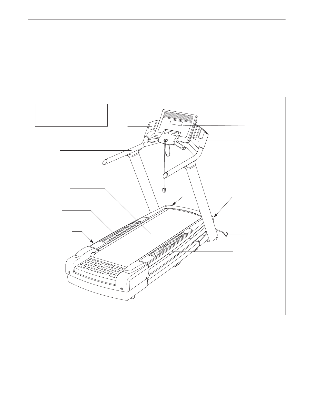
Length: 6 ft. 6 in. (198 cm)
Width: 2 ft. 9 in. (84 cm)
Handrail
Walking Belt
Accessory
Tray
ing this manual, please see the back cover of this
manual. To help us assist you, note the product model
number and serial number before contacting us. The
odel number and the location of the serial number
m
decal are shown on the front cover of this manual.
Before reading further, please familiarize yourself with
the parts that are labeled in the drawing below.
Console
Key/Clip
Roller
Adjustment
Screws
Foot Rail
Power Switch
Power Cord
Platform Cushion
5
Page 6
ASSEMBLY
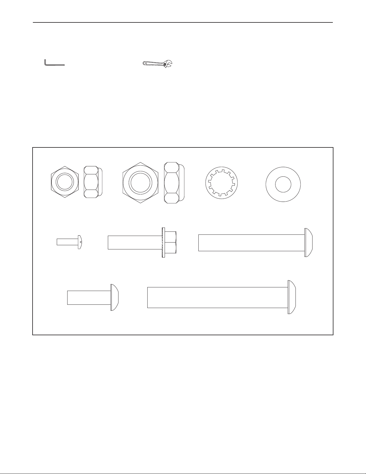
1/2" Jam Nut (5)–4
1/2" Star
Washer (7)–4
3/8" Nut (42)–2
3/8" Wheel
Washer (57)–2
3/8" x 2 1/2" Bolt (34)–2
1/2" x 3 1/4" Bolt (1)–4
5/16" x 1" Screw (2)–4
5/16" x 1 1/4"
Bolt (3)–8
#8 x 1/2"
Machine Screw
(8)–2
ssembly requires two persons. Set the treadmill in a cleared area and remove all packing materials. Do not
A
dispose of the packing materials until assembly is completed. Assembly can be completed using a 7/32" hex
key and an adjustable wrench .
ote: The underside of the treadmill walking belt is coated with high-performance lubricant. During shipping,
N
some lubricant may be transferred to the top of the walking belt or the shipping carton. This is normal and does
not affect treadmill performance. If there is lubricant on top of the walking belt, simply wipe off the lubricant with a
soft cloth and a mild, non-abrasive cleaner.
Use the drawings below to identify the assembly hardware. The number in parentheses below each drawing is
the key number of the part, from the PART LIST near the end of this manual. The number after the parentheses
shows the quantity needed for assembly. Note: Some small parts may have been preassembled. Extra hard-
ware may be included. To avoid damaging parts, do not use power tools for assembly.
6
Page 7
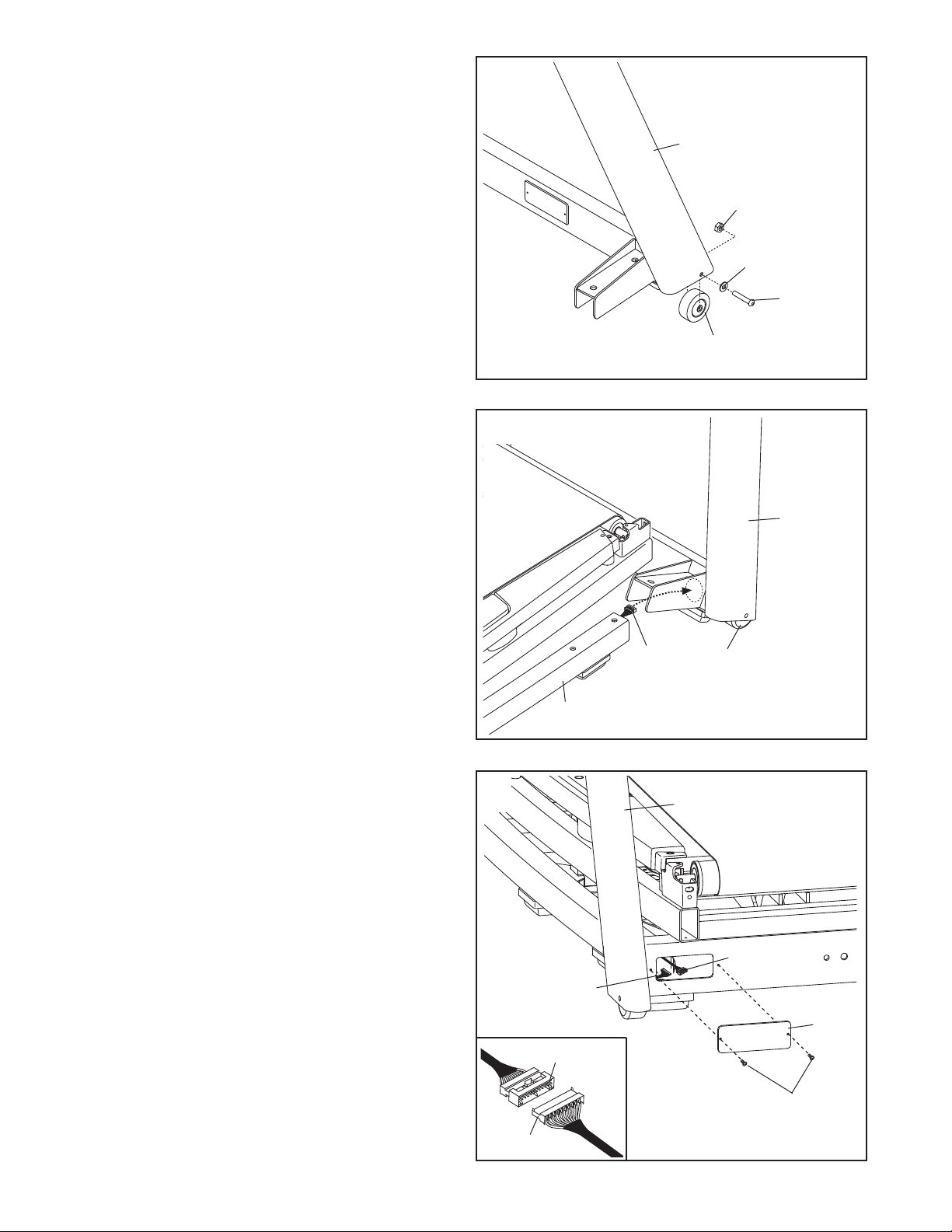
1. The Wheels (91) may be preattached. If they
are not, complete this step.
ith the help of a second person, carefully raise
W
the Upright (96) and insert a Wheel (91) into the
ottom of each side of the Upright. Be careful
b
not to pinch the 65" Wire Harness (not
shown) in the Upright.
Attach the Wheels (91) with two 3/8" x 2 1/2"
Bolts (34), two 3/8" Wheel Washers (57), and
two 3/8" Nuts (42) (only one of each is shown).
Do not overtighten the Nuts; the Wheels
must turn freely.
1
96
42
57
34
91
2. Place the Upright (96) near the front of the Base
Frame (75). Have a second person tip the
Upright back so that it rolls on the Wheels (91)
as shown. Insert the 80" Wire Harness (46) into
the round hole in the Upright.
3. Locate the 80" Wire Harness (46) and 65" Wire
Harness (48) in the Upright (96) access hole.
Connect the 80" Wire Harness (46) to the 65"
Wire Harness (48) at the front of the Upright
(96). See the inset drawing. The connectors
should slide together easily and snap into
place. If they do not, turn one connector and try
again. IF THE CONNECTORS ARE NOT INSERTED PROPERLY, THE CONSOLE MAY
BE DAMAGED WHEN THE POWER IS
TURNED ON.
2
96
46
75
3
48
91
96
46
Attach the Access Plate (9) to the Upright (96)
with two #8 x 1/2" Machine Screws (8).
9
46
8
48
7
Page 8
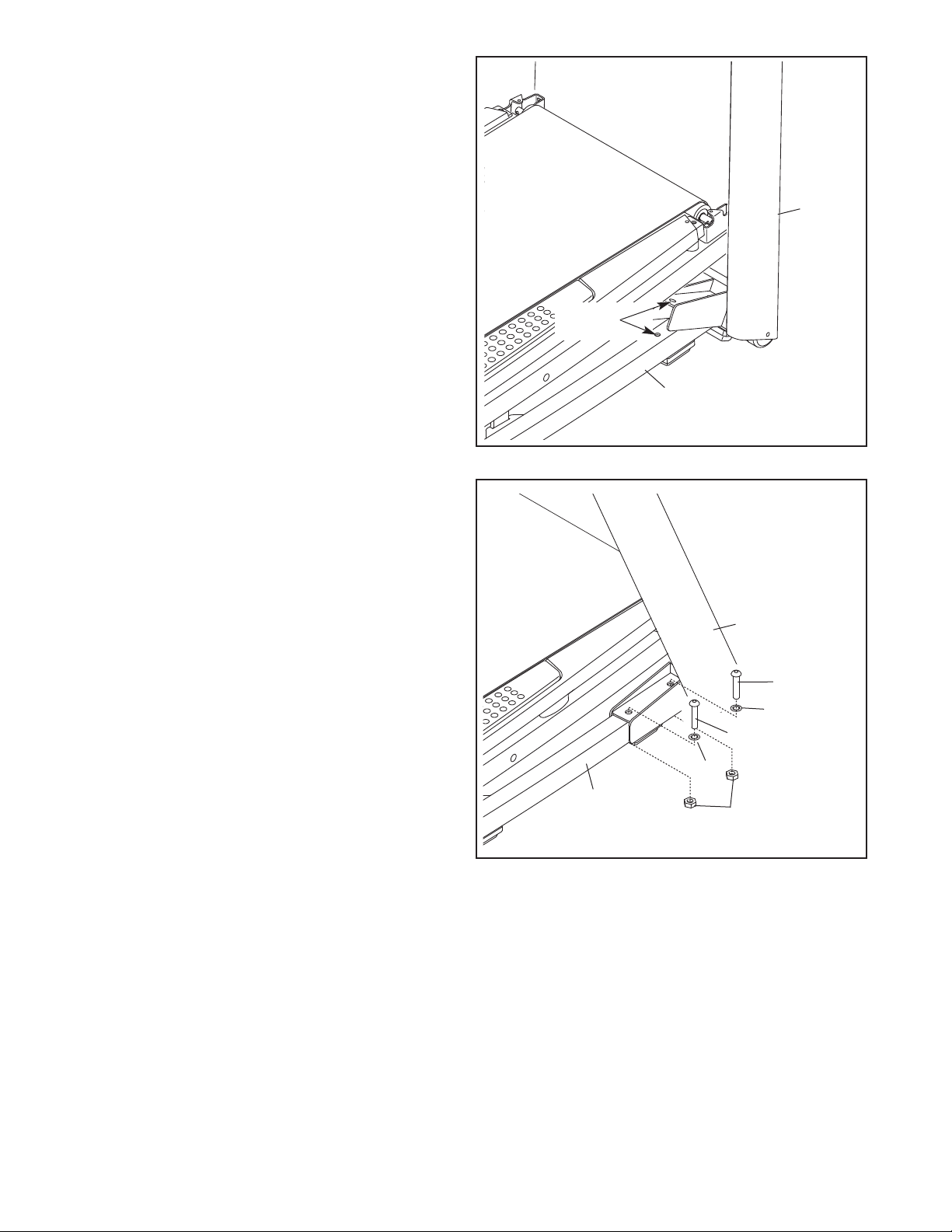
4. Align the holes in the Upright (96) above the
holes in the Base Frame (75). Lower the Upright
onto the Base Frame. Be careful not to pinch
our fingers or the Wire Harnesses (not
y
shown). Make sure to keep the holes aligned.
4
96
Holes
75
5. Tighten four 1/2" x 3 1/4" Bolts (1) with four 1/2"
Star Washers (7) and four 1/2" Jam Nuts (5)
(only two of each are shown) into the Upright
(96) and the Base Frame (75). Start all four
Bolts, and then tighten each of them.
5
96
1
7
1
7
75
5
8
Page 9
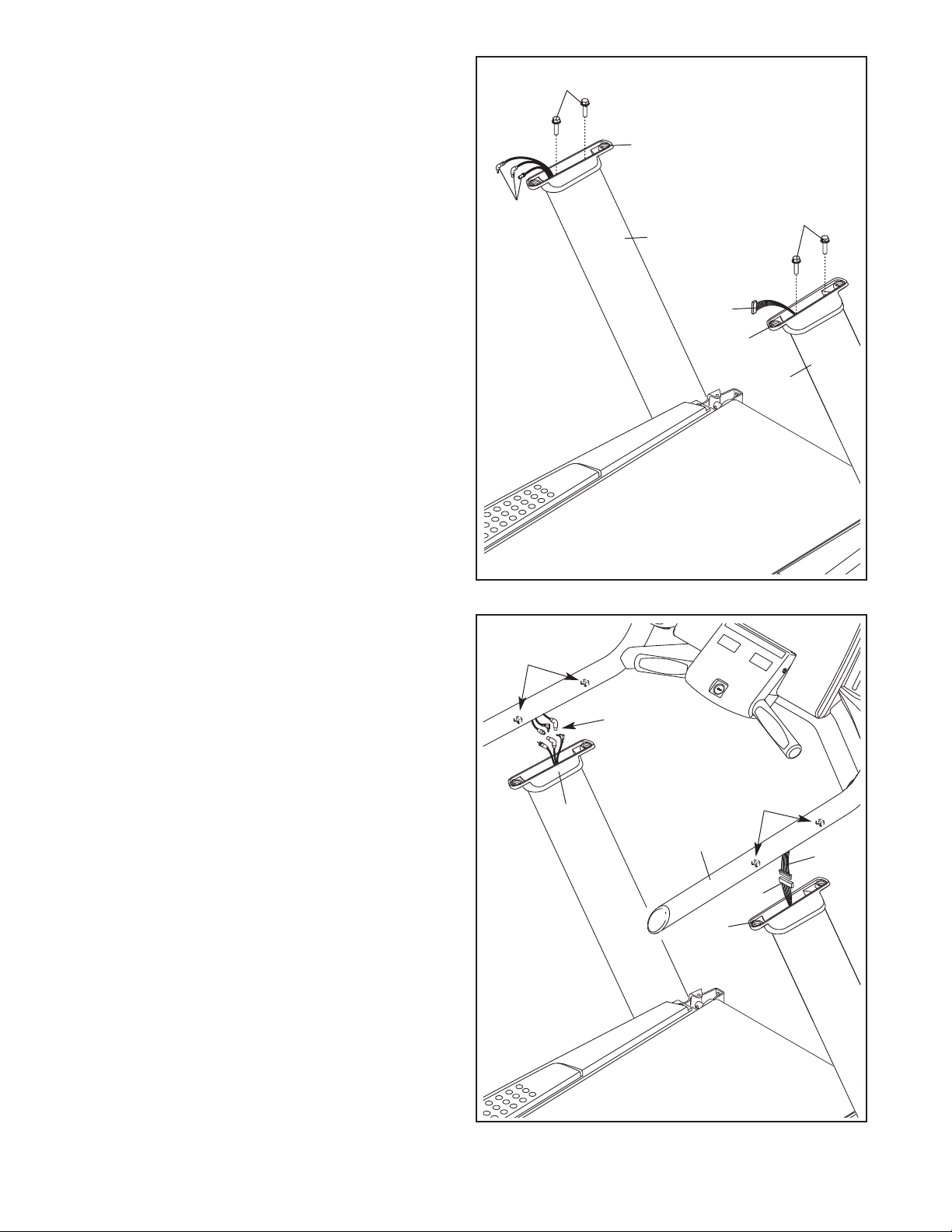
6. The Upright Brackets (98, 99) may be preattached. If they are not, complete this step.
dentify the Left Upright Bracket (99). Insert the
I
TV cables through the Left Upright Bracket.
ress the Left Upright Bracket onto the left side
P
of the Upright (96). Be careful not to pinch the
wires.
Insert the 65" Wire Harness (48) through the
Right Upright Bracket (98). Press the Right
Upright Bracket onto the right side of the Upright
(96). Be careful not to pinch the Wire
Harness.
6
ables
C
TV
3
99
3
96
48
Attach the Upright Brackets (98, 99) with four
5/16" x 1 1/4" Bolts (3).
7. Make sure the four 5/16" Cage Nuts (4) are in
the bottom of the Handrail (100) at the locations
shown. An extra 5/16" Cage Nut is included.
Have a second person hold the Handrail (100)
near the Upright Brackets (98, 99). Connect the
TV cables in the Handrail to the TV cables in the
Left Upright Bracket.
Connect the 65" Wire Harness (48) in the Right
Upright Bracket (98) to the 35" Wire Harness
(47). See the inset drawing in step 3. The
connectors should slide together easily and
snap into place. If they do not, turn one con-
nector and try again. IF YOU DO NOT CONNECT THE CONNECTORS PROPERLY, THE
CONSOLE MAY BECOME DAMAGED WHEN
YOU TURN ON THE POWER.
98
96
7
4
TV
Cables
99
100
98
4
47
48
9
Page 10
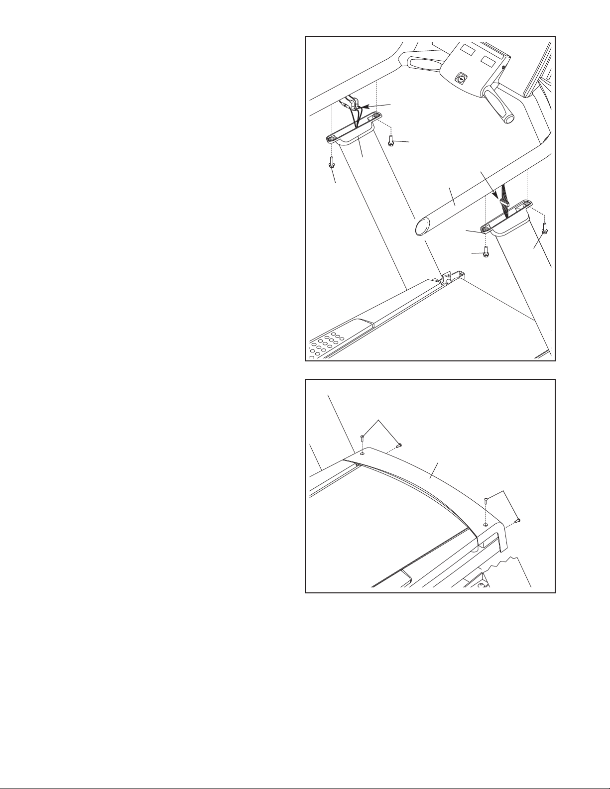
8. Insert the Wire Harnesses (47, 48) and each of
the TV cables into the Handrail (100) as you set
the Handrail on the Upright Brackets (98, 99).
e careful not to pinch the wires.
B
8
ttach the Handrail (100) to the Upright
A
Brackets (98, 99) with four 5/16" x 1 1/4" Bolts
(3). Start all four Bolts, and then tighten each
of them.
9. Attach the Front Roller Cover (68) with four
5/16" x 1" Screws (2).
TV
Cables
3
99
3
9
100
98
47, 48
3
3
2
68
2
10. Make sure that all parts are properly tightened before you use the treadmill. To protect the floor or carpet, place a mat beneath the treadmill.
10
Page 11
If you purchased the optional personal television (see HOW TO UPGRADE THE CONSOLE on page 13),
follow the steps below.
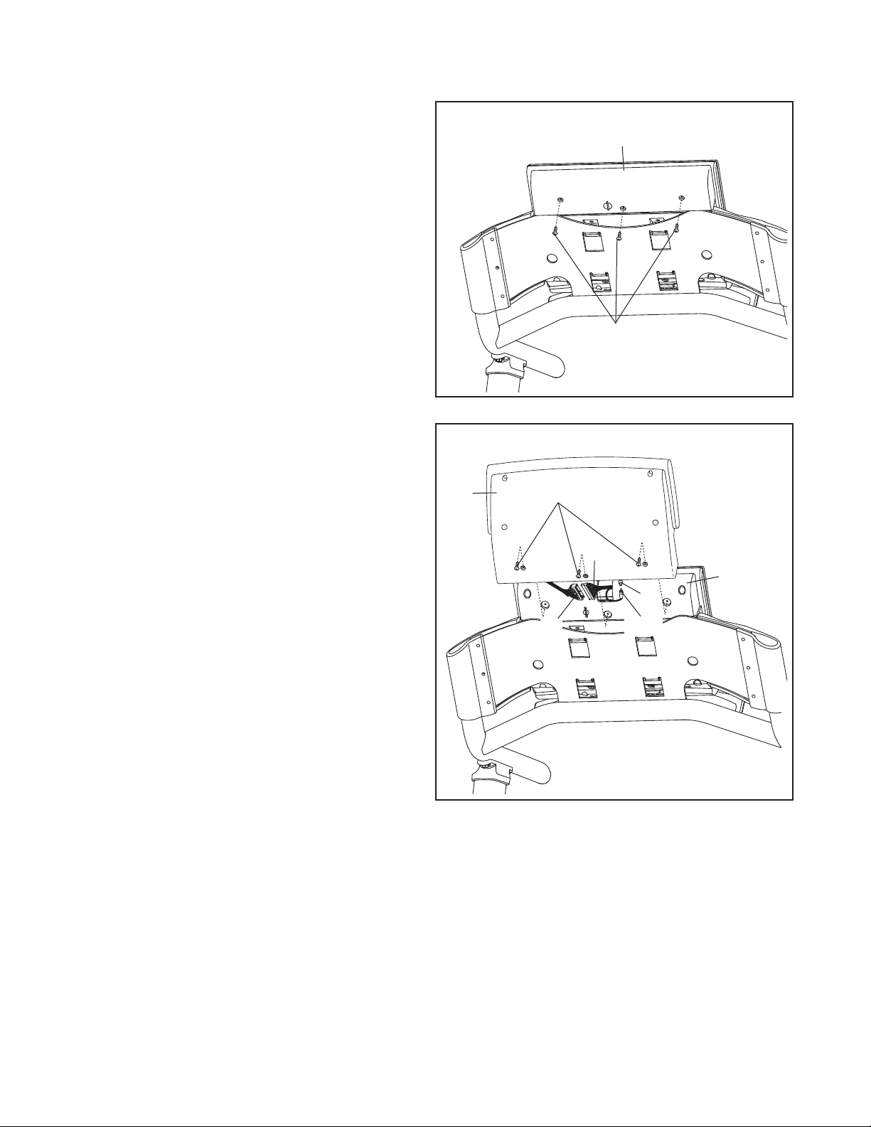
1. Remove the three #8 x 1/2" Console Cover
1
Screws (121) from the Console Cover (105).
Save the Screws for step 12. Discard the
Console Cover.
11
105
121
12. Have a second person hold the TV Console
(138) near the Console Back (49). Connect the
TV cable (A) in the TV Console to the 45" TV
Cable (125) in the Console Back.
Connect the wire harness (B) in the TV Console
(138) to the wire harness (C) in the Console
Back (49). See the inset drawing in step 3.
The connectors should slide together easily
and snap into place. If they do not, turn one
connector and try again. IF YOU DO NOT CONNECT THE CONNECTORS PROPERLY, THE
CONSOLE MAY BECOME DAMAGED WHEN
YOU TURN ON THE POWER.
Attach the TV Console (138) to the Console
Back (49) with the #8 x 1/2" Console Cover
Screws (121) you removed in step 11. Be care-
ful not to pinch the wires.
12
138
121
B
C
49
A
125
11
Page 12
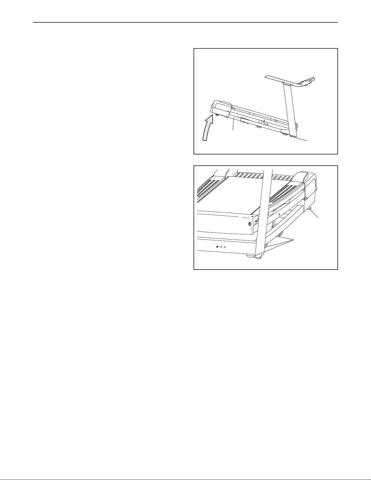
HOW TO MOVE THE TREADMILL
efore moving the treadmill, unplug the power cord.
B
Due to the size and weight of the treadmill, moving it
requires two or three persons. Hold the metal frame
firmly in the location shown at the right. CAUTION:
To decrease the possibility of damage to the treadmill or of injury, do not lift the frame by the plastic
front cover or by the handrail. Carefully roll the tread-
mill on the wheels to the desired location and then lower
it to the level position. CAUTION: To reduce the risk of
injury, use extreme caution while moving the treadmill. Do not attempt to move the treadmill over uneven surfaces.
After the treadmill is placed in the location where it will
be used, make sure that both leveling feet and the base
pads rest firmly on the floor (only one side is shown). If
the treadmill rocks even slightly, turn one of the leveling
feet clockwise or counterclockwise until the rocking motion is eliminated.
Frame
Wheels
Leveling
Foot
Base Pad
12
Page 13

HOW TO UPGRADE THE CONSOLE
This console features an optional personal television, which offers additional functionality. With the optional personal television, you can watch the television programs of your choice, or connect and use your own VCR or
VD player. To purchase the optional personal television, please see the back cover of this manual.
D
13
Page 14

OPERATION AND ADJUSTMENT
HE PRE-LUBRICATED WALKING BELT
T
Your treadmill features a walking belt coated with highperformance lubricant. IMPORTANT: Never apply sil-
cone spray or other substances to the walking
i
belt or the walking platform. Such substances will
cause excessive wear.
HOW TO PLUG IN THE POWER CORD
ance with all local codes and ordinances.
d
IMPORTANT: The treadmill is not compatible with
GFCI-equipped outlets and may not be compatible
with AFCI-equipped outlets.
This product is for use on a nominal 120-volt circuit
(see drawing 1). A temporary adapter may be used to
connect the surge suppressor to a 2-pole receptacle if
a properly grounded outlet is not available (see drawing 2).
DANGER: Improper connection
of the equipment-grounding conductor increases the risk of electric shock. Check with
a qualified electrician or serviceman if you
are unsure whether the product is properly
grounded. Do not modify the plug—if it will
not fit the outlet, have a proper outlet installed by a qualified electrician.
Your treadmill, like other electronic equipment, can be
damaged by sudden voltage changes in your homeʼs
power. To decrease the risk of damaging your
treadmill, always use a surge suppressor with your
treadmill (see drawing 1 at the right). To purchase
a surge suppressor, see precaution 13 on page 3.
Use only a single-outlet surge suppressor that is
UL 1449 listed as a transient voltage surge suppressor (TVSS). The surge suppressor must have a
UL-suppressed voltage rating of 400 volts or less
and a minimum surge dissipation of 450 joules.
The surge suppressor must be electrically rated for
120 volts AC and 15 amps. There must be a monitoring light on the surge suppressor to indicate
whether it is functioning properly. Failure to use a
properly functioning surge suppressor could damage the control system of the treadmill (see precaution 14 on page 3).
This product must be grounded. If it should malfunc-
tion or break down, grounding provides a path of least
resistance for electric current to reduce the risk of electric shock. This productʼs power cord has an equipment-grounding conductor and a grounding plug. Plug
the power cord into a surge suppressor, and plug
the surge suppressor into an appropriate outlet
that is properly installed and grounded in accor-
1
Grounded Outlet
2
Metal Screw
The temporary adapter should be used only until a
properly grounded outlet (see drawing 1) can be installed by a qualified electrician.
The green-colored rigid ear, lug, or the like extending
from the adapter must be connected to a permanent
ground such as a properly grounded outlet box cover.
The adapter must be held in place by a metal screw.
Some 2-pole receptacle outlet box covers are not
grounded. Contact a qualified electrician to determine if the outlet box cover is grounded before
using an adapter.
Grounded Outlet Box
Surge Suppressor
Grounding Pin
Grounding Pin
Grounding Plug
Grounded Outlet Box
Adapter
Lug
Grounding Plug
Surge Suppressor
14
Page 15

SPEED
CONSOLE DIAGRAM
FEATURES OF THE CONSOLE
The treadmill console offers an impressive array of
features designed to make your workouts more effective and enjoyable. When you use the manual mode of
the console, you can change the speed and incline of
the treadmill with the touch of a button. As you exercise, the console will display continuous exercise feedback.
In addition, the console features fourteen personal
trainer workouts. Each preset workout automatically
controls the speed and incline of the treadmill as it
guides you through an effective workout.
The console also offers twelve interactive trainer workouts that allow you to customize your workout. The interactive trainer workouts include three heart rate
workouts that control the speed and incline of the
treadmill to keep your heart rate near the target heart
rate settings. In addition, three fitness test workouts
measure your fitness level or your VO
2 max.
The console also features the iFit interactive workout
system. The iFit system accepts iFit cards with work-
outs that help you achieve specific fitness goals. For
example, lose unwanted pounds with the 8-week
Weight Loss workout. iFit workouts automatically control the treadmill. iFit cards are available separately. To
purchase iFit cards at any time, go to www.iFit.com
or call the telephone number on the back cover of
this manual. iFit cards are also available at select
stores.
Whether you select the manual mode or a preset workout, you can watch the television programs of your
choice on the optional personal television. You can
even listen to your favorite workout music or audio
books with the consoleʼs stereo sound system.
To turn on the power, see on page 16. To use the
manual mode, see page 16. To use a personal
trainer workout, see page 18. To use a walk/run
workout or a manual control workout, see page 20.
To use a fitness test workout, see page 21. To use
a heart rate workout, see page 22. To use a custom
workout, see page 23. To use an iFit workout, see
page 24. To use the maintenance mode, see page
25. To use the stereo sound system, see page 25.
15
Page 16

HOW TO TURN ON THE POWER
HOW TO USE THE MANUAL MODE
IMPORTANT: If the treadmill has been exposed to
old temperatures, allow it to warm to room tem-
c
perature before turning on the power. If you do not
o this, the console displays or other electrical
d
components may become damaged.
Plug in the power cord (see
page 14). Next, locate the
power switch on the treadmill frame near the power
cord. Make sure that the
switch is in the reset
position.
Next, stand on the foot rails
of the treadmill. Locate the
clip attached to the key, and
slide the clip securely onto
the waistband of your
clothes. Then, insert the
key into the console. After a
moment, the displays will
light. IMPORTANT: In an emergency, the key can be
pulled from the console, causing the walking belt
to slow to a stop. Test the clip by carefully taking a
few steps backward; if the key is not pulled from
the console, adjust the position of the clip.
IMPORTANT: If there is a sheet of plastic on the
face of the console, remove the plastic. To prevent
damage to the walking platform, wear clean athletic shoes while using the treadmill. The first time
the treadmill is used, observe the alignment of the
walking belt, and center the walking belt if necessary (see page 31).
Note: Your console will display speed and distance in
either miles or kilometers. For simplicity, all instructions
in this section refer to miles.
Reset
Key
Clip
1. Insert the key into the console.
See HOW TO TURN ON THE POWER at the left.
2. Select the manual mode.
Each time the key
is inserted, the
manual mode will
be selected. If you
have selected a
workout, press any
of the workout buttons repeatedly until zeros appear in the display.
3. Start the walking belt and adjust the speed.
To start the walking belt, press the Start/Stop button, the Speed increase button, or one of the Quick
Touch Speed buttons numbered 1 to 12. As you
exercise, change the speed of the walking belt as
desired by pressing the Speed increase and decrease buttons next to the Start/Stop button. Each
time you press a button, the speed setting will
change; if you hold down a button, the speed setting will change in larger increments. After you
press one of the Quick Touch Speed buttons, press
the Enter button or press the speed button again to
confirm the speed.
To stop or restart the walking belt, press the
Start/Stop button.
4. Change the incline of the treadmill as desired.
To change the incline of the treadmill, press the
Incline increase or decrease button. Each time you
press one of the buttons, the incline will gradually
change until it reaches the selected incline setting.
16
Page 17

5. Select a display mode and monitor your
progress with the display.
hen the manual
W
mode is selected,
he console offers
t
seven display
modes. The display mode that you
select will determine which workout information is
shown. Press the Display button repeatedly to select the desired display mode.
As you walk or run on the treadmill, the upper display can show the following workout information:
• The elapsed time.
• The distance that you have walked or run.
• The speed of the walking belt.
6. Measure your heart rate if desired.
Before using
he handgrip
t
pulse sensor,
emove the
r
sheets of plastic from the
metal contacts.
In addition,
make sure that
your hands are
clean.
To measure your heart rate, stand on the foot
rails. Hold the contacts for approximately ten
seconds—avoid moving your hands. When your
pulse is detected, your heart rate will be shown.
For the most accurate heart rate reading, continue to hold the contacts for about 15 seconds.
Contacts
• The incline level of the treadmill.
• The approximate number of calories you have
burned.
• The approximate number of calories burned per
hour.
• Your exercise intensity in METs. One MET is the
amount of energy you use while at rest.
• Your walking or running pace, in minutes per mile
or minutes per kilometer.
• Your power output in watts.
• An animation of a road.
Regardless of which display mode you select, the
speed or incline setting will appear in the display for
a few seconds each time you change the setting.
As you switch between workouts and the manual
mode, the console will keep track of the total distance that you have walked or run and the approximate number of calories you have burned. You can
keep your totals even when you switch to a new
workout. To reset the console, press the Clear button.
7. Turn on the fan if desired.
The fan has high and low speed settings. Press the
Fan button repeatedly to select a fan speed or to
turn off the fan. Note: If the fan is on when the
walking belt stops, the fan will automatically turn off
after a few minutes.
8. When you are finished exercising, remove the
key from the console.
Step onto the foot rails, press the Stop button, remove the key from the console, and put it in a secure
place.
When you are finished using the treadmill, press
the power switch into the off position and unplug
the power cord. IMPORTANT: If you do not do
this, the treadmillʼs electrical components may
wear prematurely.
17
Page 18

HOW TO USE A PERSONAL TRAINER WORKOUT
1. Insert the key into the console.
See HOW TO TURN ON THE POWER on page
6.
1
2. Select one of the personal trainer workouts.
To select a personal trainer
workout, press
the Random
Workouts button,
the Interval
Workouts button, or the Terrain Workouts button repeatedly until the name of the desired workout appears in the display. Random workouts use preset
random speed and incline settings. Interval workouts use speed settings to provide a personalized
workout. Terrain workouts use speed and incline
settings to simulate an actual walking experience.
When a workout is selected, the display will show
the name, the maximum incline setting, the maximum speed setting and the duration of the workout. The display will also show a profile of the
speed settings of the workout.
Press the Enter button to select the desired workout. Select your age, your weight, and the workout
duration using the Increase and Decrease buttons
next to the Enter button. Press the Enter button
after each selection. Note: To use the Interval
workouts, you must also enter your minimum and
maximum speed settings using the Quick Touch
peed buttons or the Speed Increase and
S
Decrease buttons.
3. Press the Start/Stop button to start the workout.
A moment after you press the Start/Stop button,
the treadmill will automatically adjust to the first
speed and incline settings of the workout. Hold the
handrails and begin walking.
Each workout is divided into segments. One speed
setting and one incline setting are programmed for
each segment. Note: The same speed and/or incline
setting may be programmed for consecutive segments.
During the workout,
the profile will
show your
progress. The
flashing segment
of the profile represents the current
segment of the workout. The height of the flashing
segment indicates the speed setting for the current
segment. At the end of each segment, the next segment of the profile will begin to flash and the speed
and incline settings will appear at the top of the display for a few moments to alert you.
Current Segment
18
Page 19

The workout will continue in this way until the last
segment of the profile flashes in the display and
the last segment ends. The walking belt will then
low to a stop.
s
f the speed or incline setting is too high or too low
I
at any time during the workout, you can manually
override the setting by pressing the Speed or
Incline buttons; however, when the next segment
of the workout begins, the treadmill will automatically adjust to the speed and incline settings for the next segment. Note: If you use an
Interval workout, the incline will not adjust automatically.
The display can show the speed of the walking belt,
the incline of the treadmill, a profile of the workout,
the time remaining in the workout, the distance you
ave walked or run, the approximate number of
h
calories you have burned, your exercise intensity in
ETs, the approximate number of calories burned
M
per hour, your pace, and your power output in
watts.
5. Measure your heart rate if desired.
See step 6 on page 17.
6. Turn on the fan if desired.
To stop or restart the workout at any time, press
the Start/Stop button.
4. Select a display mode and monitor your
progress with the display.
The console offers three display modes. The display mode that you select will determine which
workout information is shown. Press the Display
button repeatedly to select the desired display
mode.
See step 7 on page 17.
7. When you are finished exercising, remove the
key from the console.
See step 8 on page 17.
19
Page 20

HOW TO USE A WALK/RUN WORKOUT OR A
MANUAL CONTROL WORKOUT
. Insert the key into the console.
1
ee HOW TO TURN ON THE POWER on page
S
16.
2. Select one of the workouts.
To select a walk/run workout, press the Walk/Run
Workouts button repeatedly until the 5K Walk, the
10K Walk, or the Cross Country workout appears in
the display.
To select a manual control workout, press the
Manual Control
button repeatedly
until the Manual
Time, the Manual Distance, or the Manual Calories
workout appears in the display.
3. Press the Start/Stop button to start the workout.
A moment after you press the Start/Stop button,
he walking belt will begin moving. Hold the
t
handrails and begin walking.
During the workout, the profile will show the incline
of the walking belt. As you exercise, change the
speed and incline of the walking belt as desired by
pressing the Speed and Incline increase and decrease buttons.
The workout will continue until you reach your time,
distance, or calorie goal. The walking belt will then
slow to a stop.
To stop or restart the workout at any time, press
the Start/Stop button.
4. Select a display mode and monitor your
progress with the display.
See step 4 on page 19.
The display will show the name, the maximum incline setting, the maximum speed setting, and the
duration of the workout.
Press the Enter button to select the desired workout. Select your age and then your weight using
the Increase and Decrease buttons next to the
Enter button. Press the Enter button after each
selection. Note: To use the cross country workouts, you must also enter your distance goal. To
use a manual control workout, enter your time, distance, or calorie goal.
5. Measure your heart rate if desired.
See step 6 on page 17.
6. Turn on the fan if desired.
See step 7 on page 17.
7. When you are finished exercising, remove the
key from the console.
See step 8 on page 17.
20
Page 21

HOW TO USE A FITNESS TEST WORKOUT
The fitness test workouts measure your relative fitness
evel. For the most accurate results, use a fitness test
l
workout when you are not feeling tired, when you have
ot eaten for at least two hours, and when you have
n
not exercised for at least 24 hours.
The treadmill features three fitness workouts. The
Ebbeling Fitness Test measures VO
2 max, or aerobic
capacity, and lasts 9 minutes. The Gerkin Fitness Test
also measures VO2 max. The Gerkin Fitness Test begins with a three-minute warm-up period and ends
after either 14 minutes or when you reach a certain
heart rate. The FreeMotion Fitness Test measures
your fitness level on a scale of 1 to 10. The FreeMotion
Fitness Test ends after either 28 minutes or when you
reach a certain heart rate.
1. Put on a Polar®-compatible heart rate monitor
(not included).
To use a fitness test, you must wear a Polar-compatible heart rate monitor or use the handgrip pulse
sensor. Note: For best results, you should wear a
heart rate monitor. No heart rate monitor is included.
2. Insert the key into the console.
4. Press the Start/Stop button to start the workout.
moment after you press the Start/Stop button,
A
the treadmill will automatically adjust to the first
peed and incline settings of the fitness test. Begin
s
walking on the treadmill. Note: For the most accurate results, do not hold the handrails during a fitness test workout.
During the workout, the speed and incline of the
treadmill will periodically change. The speed setting or the incline setting will appear in the display
to alert you before each change. IMPORTANT:
The Speed and Incline buttons will not function
during a fitness test workout.
Note: If you press the Start/Stop button during the
fitness test, the fitness test will end.
When the workout ends, the walking belt will slow
to a stop and your fitness level or VO
2 max will ap-
pear in the display.
If your pulse is not detected during the workout, the
words CHECK HEART RATE MONITOR will appear in the display and the speed of the treadmill
may automatically decrease. If your pulse is still
not detected, the fitness test will be aborted.
See HOW TO TURN ON THE POWER on page
16.
3. Select a fitness test workout.
To select a fitness test workout, press the Fitness
Tests button repeatedly until the name of the desired fitness test appears in the display.
Press the Enter button to select the desired workout. Select your age and then your weight using
the Increase and Decrease buttons next to the
Enter button. Press the Enter button after each
selection. Note: To use the Ebbeling Fitness Test,
you must also enter your gender.
5. Select a display mode and monitor your
progress with the display.
See step 4 on page 19. Note: The fitness tests will
display your fitness level instead of your exercise
intensity in METs.
6. Turn on the fan if desired.
See step 7 on page 17.
7. When you are finished exercising, remove the
key from the console.
See step 8 on page 17.
21
Page 22

HOW TO USE A HEART RATE WORKOUT
CAUTION: If you have heart prob-
lems, or if you are over age 60 and have been
inactive, do not use the heart rate workouts. If
you are taking medication regularly, consult
our physician to find out whether the medica-
y
tion will affect your exercise heart rate.
mill will automatically adjust to the first speed and
incline settings of the workout. Hold the handrails
and begin walking.
The heart rate workouts are divided into several
ne-minute segments. One target heart rate setting
o
is programmed for each segment. The same target
heart rate setting may be programmed for consecutive segments. For a shorter workout, simply stop
the workout before it ends.
1. Put on a Polar®-compatible heart rate monitor
(not included).
To use a heart rate program, you must wear a
Polar-compatible heart rate monitor or use the
handgrip pulse sensor. Note: For best results, you
should wear a heart rate monitor. No heart rate
monitor is included.
2. Insert the key into the console.
See HOW TO TURN ON THE POWER on page
16.
3. Select one of the heart rate workouts.
To select a heart rate workout, press the Heart
Rate Control button repeatedly until the desired
workout appears in the display. Press the Enter
button to select the desired workout.
Select your age and then your weight using the
Increase and Decrease buttons next to the Enter
button. Press the Enter button after each selec-
tion. Note: To use the constant heart rate and variable heart rate workouts, you must also enter your
target maximum heart rate. If the target maximum
heart rate setting is changed, the intensity level of
the entire workout will change. Note: To calculate
your target maximum heart rate see EXERCISE
INTENSITY on page 32.
During all heart rate workouts, the console will regularly compare your heart rate to the target heart
rate setting. If your heart rate is too far below or
above the target heart rate setting for the current
segment, the speed of the walking belt will automatically increase or decrease to bring your heart
rate closer to the target heart rate setting.
If the speed or incline setting is too high or too low
at any time during the workout, you can adjust the
setting with the Speed or Incline buttons. However,
each time the console compares your heart
rate to the target heart rate setting, the speed
of the treadmill may automatically change to
bring your heart rate closer to the target heart
rate setting.
To stop or restart the workout at any time, press
the Start/Stop button.
5. Select a display mode and monitor your
progress with the display.
See step 4 on page 19.
6. Turn on the fan if desired.
See step 7 on page 17.
7. When you are finished exercising, remove the
key from the console.
4. Press the Start/Stop button to start the workout.
A moment after you press the Start/Stop button,
the walking belt will begin to move and the tread-
See step 8 on page 17.
22
Page 23

HOW TO USE A CUSTOM WORKOUT
1.
Insert the key into the console.
See HOW TO TURN ON THE POWER on page
6.
1
.
2
Select one of the custom workouts.
To select a custom workout, press the Custom
Workouts button repeatedly until the desired workout
appears in the display.
The display will show the name, the maximum incline setting, the maximum speed setting, and the
duration of the workout. Note: To create a custom
workout, see step 3 on page 25.
Press the Enter button to select the desired workout. Select your age and then your weight using
the Increase and Decrease buttons next to the
Enter button.
3.
Press the Start/Stop button to start the workout.
A moment after you press the Start/Stop button,
the treadmill will automatically adjust to the first
speed and incline settings that you programmed
previously. Hold the handrails and begin walking.
Each custom workout is divided into one-minute
segments. One speed setting and one incline setting are programmed for each segment.
During the workout, the profile will
show your
progress. The
flashing segment
of the profile represents the current segment of the workout. The height of the
flashing segment indicates the incline setting for the
Current Segment
current segment. At the end of each segment, a series of tones will sound, the next segment of the
profile will begin to flash, and the speed or incline
etting for the next segment will appear in the dis-
s
play to alert you.
The workout will continue in this way until the last
segment of the profile flashes in the display and
the last segment ends. The walking belt will then
slow to a stop.
If the speed or incline setting is too high or too low
at any time during the workout, you can manually
override the setting by pressing the speed or incline
buttons; however, when the next segment of the
workout begins, the treadmill will automatically
adjust to the speed and incline settings for the
next segment.
To stop or restart the workout at any time, press
the Start/Stop button. The speed of the walking belt
will gradually increase to the speed setting of the
current segment.
4. Select a display mode and monitor your
progress with the display
See step 4 on page 19.
5.
Measure your heart rate if desired.
See step 6 on page 17.
6.
Turn on the fan if desired.
See step 7 on page 17.
7.
When you are finished exercising, remove the
key from the console.
See step 8 on page 17.
.
23
Page 24

HOW TO USE AN IFIT WORKOUT
1. Insert the key into the console.
See HOW TO TURN ON THE POWER on page
6.
1
At the end of each one-minute segment, the speed
and incline settings for the next segment will appear
in the display and a series of tones will sound to
lert you. If a different speed and/or incline setting
a
is programmed for the next segment, three tones
ill sound.
w
2. Insert an iFit card and select a workout.
To use an iFit workout, insert an iFit card into the
iFit slot on the back of the console; make sure that
the iFit card is oriented so the missing corner is
facing downward and is inserted into the iFit slot.
iFit Slot
iFit Card
Next, select an iFit workout by pressing the
Increase and Decrease buttons next to the Enter
button. When an iFit workout is selected, the display will show the name of the workout, the maximum incline setting and the maximum speed setting of the workout, and the workout time.
If the speed or incline setting for the current segment is too high or too low, you can manually override the setting by pressing the Speed or Incline
buttons; however, when the next segment be-
gins, the treadmill will automatically adjust to
the speed and incline settings for the next segment.
To stop the workout at any time, press the
Start/Stop button. To restart the workout, press the
Start/Stop button or the Speed increase button.
The walking belt will begin to move. When the next
segment of the workout begins, the treadmill will automatically adjust to the speed and incline settings
for the next segment.
4. Select a display mode and monitor your
progress with the display.
See step 4 on page 19.
5. Measure your heart rate if desired.
See step 6 on page 17.
Each iFit workout is divided into one-minute segments. One speed setting and one incline setting
are programmed for each segment. Note: The
same speed and/or incline setting may be programmed for consecutive segments.
3. Press the Start/Stop button to start the workout.
A moment after you press the button, the treadmill
will automatically adjust to the first speed and incline settings of the workout. Hold the handrails
and begin walking.
6. Turn on the fan if desired.
See step 7 on page 17.
7. When you are finished exercising, remove the
key from the console.
See step 8 on page 17.
CAUTION: Always remove iFit cards from the
iFit slot when you are not using them.
24
Page 25

HOW TO USE THE MAINTENANCE MODE
The console has a maintenance mode that keeps track
f the total number of hours that the treadmill has been
o
operated and the total distance that the walking belt
as moved. The maintenance mode also allows you to
h
adjust the maximum workout time, the pause timeout,
and the sleep timeout. You can also select the desired
language and disable or enable the safety key.
1. Select the maintenance mode.
To select the maintenance mode, hold down the
Clear button and the Enter button for three seconds.
Press the Display button to move between
screens. Press the Back button to return to a previous screen. To change the settings, press the
Increase and Decrease buttons next to the Enter
button.
2. Set user preferences.
When you select the maintenance mode, the display will show the total number of hours and the
total number of miles (or kilometers) that the walking belt has moved. Press the Display button to
move to the next screen.
Press the Display button to move to the next
screen. You may be able to select one of five languages for the displays. If desired, select a lan-
uage for the displays.
g
. Create custom workouts.
3
If desired, create a custom workout. Press the
Display button until the desired custom workout is
shown. Then press the Enter button. Program a
speed setting and an incline setting for the first
one-minute segment by pressing the Speed and
Incline buttons. Press the Enter button to move to
the next segment and continue programming segments for 30 segments. Press the Enter button
after you have programmed the last segment.
Then press the Display button until you exit the information mode.
4. Enable or disable the safety key.
If desired, disable or enable the safety key. When
the safety key is enabled, the key must be inserted
into the console for the treadmill to turn on. To disable the safety key, push the Increase or Decrease
button. Note: To disable or enable the safety key,
you must remove the key from the console before
you enter the maintenance mode. For best results,
operate the treadmill with the safety key enabled.
If desired, set the maximum workout time for the
Random, Interval, Terrain, Manual Time, and Heart
Rate workouts using the Increase and Decrease
buttons.
Next, press the Display button to move the cursor
to the pause timeout. Set the pause timeout, if desired. The pause timeout begins when the walking
belt stops. When the pause timeout ends, the display will return to the main screen and your distance and calories count will be reset.
Press the Display button to move the cursor to the
sleep timeout. Set the sleep timeout, if desired.
The sleep timeout begins when the display returns
to the main screen. When the sleep timeout ends,
the incline will lower to the lowest setting and the
screen saver will appear.
Next, press the Display button to move to the next
screen. Set the default input, if desired. To use the
optional TV, select the TV mode. To use a VCR or
DVD player with the optional TV, select the RCA
mode. To use a personal media player, select the
MP3 mode.
To exit the maintenance mode at any time, remove the
key from the console.
HOW TO USE THE STEREO SOUND SYSTEM
To play music or audio books through the consoleʼs
stereo speakers, you must connect your MP3 player,
CD player, or other personal audio player to the console. Locate the audio wire and plug it into the MP3
jack near the Start/Stop button. Then, plug the other
end into a jack on your MP3 player, CD player, or
other personal audio player. Make sure that the
audio wire is fully plugged in.
Next, press the Play button on your MP3 player, CD
player, or other personal audio player. Then, adjust the
volume on your personal audio player.
If you are using a personal CD player and the CD
skips, set the CD player on the floor or another flat surface instead of on the console.
25
Page 26

PREVENTIVE MAINTENANCE
Regular maintenance is necessary for optimal performance and long life of the treadmill. Please read and
follow all instructions below. If the treadmill is not maintained as described, components may wear ex-
essively, the treadmill may be damaged, and the warranty will be voided. If you have questions about
c
maintenance, please see the back cover of this manual. CAUTION: Make sure to remove the key and unplug
he power cord before performing any maintenance procedures.
t
WEEKLY MAINTENANCE
1. Unplug the power cord. Inspect and properly tighten all external parts of the treadmill.
2. Apply a mild multi-purpose cleaner to a 100% cotton cloth and remove any dust and grime from the handrails,
upright, foot rails, frame, and motor hood. In addition, wipe the walking platform along the sides of the walking
belt. Do not wipe under the walking belt. Apply a small amount of mild multi-purpose cleaner to a 100% cotton cloth and wipe the console and the screens. Do not spray cleaner directly onto the treadmill or use
ammonia or acid-based cleaners.
3. Make sure that the walking belt is centered and properly tightened. If it is centered and runs smoothly, do not
make any adjustments. If the walking belt needs to be adjusted, see pages 30 and 31.
MONTHLY MAINTENANCE
1. Unplug the power cord. Remove the two 1/4" x 3/4" Screws
(23) and the two 1/2" x 1" Screws (37) attaching the Motor
Hood (82), and lift off the Motor Hood.
2. Using a hand-held vacuum, clean the area under the Motor
Hood (not shown). Be careful to avoid touching any com-
ponents. Check the Drive Belt (45) for wear and cracks. If
the Drive Belt needs to be replaced, please see the back
cover of this manual.
3. Plug in the power cord and insert the key into the console. Press the Start/Stop button. IMPORTANT: Be
careful to avoid injury; keep your hands away from moving parts and make sure that your clothes cannot become caught in moving parts. While the walking belt is moving, check the treadmill for unusual
noises or odors. If any of these problems exist, please see the back cover of this manual. Remove the key
and unplug the power cord. Reattach the Motor Hood (82) with the two 1/4" x 3/4" Screws (23) and the two
1/2" x 1" Screws (37).
1
23
37
82
37
2
45
23
26
Page 27

REPLACING THE WALKING BELT
When the walking belt becomes worn, it should be replaced. The walking belt will need to be replaced after every
0,000 to 15,000 miles (16,000 to 24,000 kilometers). See the Service Manual for replacement instructions.
1
Please see the back cover of this manual to order a new walking belt.
REPLACING THE WALKING PLATFORM
When both sides of the walking platform become worn, the walking platform should be replaced. The walking
platform will need to be replaced after every 20,000 to 30,000 miles (32,000 to 48,000 kilometers). Please see
the back cover of this manual to order a new walking platform. Follow the instructions below to replace the walking platform.
TURNING THE WALKING PLATFORM
Both sides of the walking platform are designed to be used as walking surfaces. Inspect the walking platform periodically for wear. If there is any wood showing through the phenolic coating, or if the surface is damaged, the
walking platform should be turned over. The walking platform will need to be turned over and the walking belt replaced (see above) after every 10,000 to 15,000 miles (16,000 to 24,000 kilometers). Follow the instructions
below to turn over the walking platform.
1. Remove the key and unplug the
power cord. Remove the four 5/16"
x 1" Screws (2) and the Front Roller
Cover (68). Remove the two 5/16" x
4 3/8" Screws (29) and the two
5/16" Star Washers (54).
2. Remove the Left and Right Foot
Rail Covers (58, 70). Remove the
#12 x 1" Screws (20) and the Left
and Right Foot Rails (59, 71).
Remove the 1/4" x 1 1/2" Screws
(111), the 3/8" x 1 3/4" Bolts (112),
and the 3/8" Platform Nuts (113).
Remove the #10 x 1 1/2" Bolts (21)
and the Roller Guards (74).
Lift the Front Roller (67) and slide it
out of the Walking Belt (64).
1
2
68
20
54
20
2
29
111
20
71
111
67
64
29
54
2
59
20
74
113
112
58
20
20
70
21
112
21
27
113
74
Page 28

3. Note: Be very careful to avoid
chipping or damaging the phenolic coating on the Walking
latform (63). Lift the Walking
P
Platform and the Walking Belt (64)
o the position shown by the dotted
t
lines. Slide the Walking Platform
out of the Walking Belt, turn it, and
then slide it back into the Walking
Belt. Note: If you are replacing the
Walking Platform, slide the new
Walking Platform into the Walking
Belt.
3
64
67
Lay down the Walking Platform (63)
and the Walking Belt (64). Slide the
Front Roller (67) back into the
Walking Belt.
4. See step 1. Reattach the 5/16" x 4 3/8" Screws (29) and the 5/16" Star Washers (54). Make sure that the
walking belt is centered. Do not fully tighten the Screws; the Screws should only be tight enough to
remove the slack from the walking belt.
5. See step 2. Reattach the Roller Guards (74), the Walking Platform (63), the Foot Rails (59, 71), and the Foot
Rail Covers (58, 70).
6. See step 1. Reattach the Front Roller Cover (68). Make sure that the Walking Belt (64) is centered on the
Front Roller (67). Then, partially tighten the 5/16" x 4 3/8" Screws (29) until the Walking Belt cannot be
pushed to the left or right on the Front Roller. Make sure to turn both Screws the same number of times.
7. The tension of the Walking Belt (64) now needs to be ad-
justed. Turn each 5/16" x 4 3/8" Screw (29) clockwise four
times. Center the Walking Belt if necessary (see page 31).
Then, step onto the Foot Rails (59, 71), insert the key into
the console, and press the Start/Stop button. Hold the
handrails and gently press one foot against the moving
Walking Belt. If the Walking Belt stops moving, remove the
key from the console and turn each Screw one more time.
Continue to test the tension of the Walking Belt until the
Walking Belt no longer slips. Make sure to keep the Walking
Belt centered. If the Front Roller (67) stops moving, do
not further tighten the Screws; please see the back cover
of this manual.
7
29
67
63
71
64
59
29
IMPORTANT: The ideal tension is just enough to prevent the walking belt from slipping. This will maximize the life of the walking belt, the roller, and the drive system. Overtightening the walking belt can
lead to premature walking belt failure and excess wear to the bearings and drive components.
28
Page 29

SIX-MONTH PREVENTIVE MAINTENANCE RECORD
Photocopy this form and use it to record the preventive maintenance performed on the treadmill. Each copy of the
orm can be used for six months (26 weeks). When maintenance is performed, write the date in the appropriate
f
spaces. Make sure to perform each maintenance procedure as described on pages 26 to 28. If the proce-
ures are not performed as described, components may wear excessively, the treadmill may be damaged,
d
and the warranty will be voided.
Week1
Week2
Week3
Week4
Week5
Week6
Week7
Week8
Week9
Week10
Week11
Week12
Weekly Maintenance
Inspect and
tighten all external parts of
the treadmill.
/ /
/ /
/ / / /
/ / / /
/ / / /
/ / / /
/ / / /
/ / / /
/ / / /
/ / / /
/ / / /
/ / / /
Clean the
treadmill.
/ /
/ /
Check the
walking belt for
proper tension
and alignment.
/ /
/ /
/ /
/ /
/ /
/ /
/ /
/ /
/ /
/ /
/ /
/ /
Monthly Maintenance
Remove the
motor hood and
vacuum the
motor compartment.
Check the
motor belt for
cracks and
other wear.
/ / / / / /
/ / / / / /
Check the
motor for arcing; check for
noises or
odors.
Week13
Week14
Week15
Week16
Week17
Week18
Week19
Week20
Week21
Week22
Week23
Week24
Week25
Week26
Walking Platform Turned/Replaced Walking Belt Replaced
/ / / /
/ / / /
/ / / /
/ / / /
/ / / /
/ / / /
/ / / /
/ / / /
/ / / /
/ / / /
/ / / /
/ / / /
/ / / /
/ / / /
/ /
/ /
/ /
/ /
/ /
/ /
/ /
/ /
/ /
/ /
/ /
/ /
/ /
/ /
/ /
/ / / / / /
/ / / /
/ / / / / /
/ / / / / /
/ / / /
/ /
29
Page 30

TROUBLESHOOTING
Most treadmill problems can be solved by following
the simple steps below. Find the symptom that
applies, and follow the steps listed. If further assis-
ance is needed, see the back cover of this manual.
t
YMPTOM: The power does not turn on
S
a. Make sure that the power cord is plugged into a
surge suppressor and that the surge suppressor is
plugged into a properly grounded outlet (see page
14). Use only a single-outlet surge suppressor that
meets all of the specifications described on page
14. IMPORTANT: The treadmill is not compati-
ble with GFCI-equipped outlets and may not be
compatible with AFCI-equipped outlets.
b. After the power cord has been plugged in, make
sure that the key is inserted into the console.
c. Check the power switch located on the treadmill
frame near the power cord. If the switch protrudes
as shown, the switch has tripped. To reset the
power switch, wait for five minutes and then press
the switch back in.
SYMPTOM: The walking belt slows when walked
on
. Use only a single-outlet surge suppressor that
a
meets all of the specifications described on page
4.
1
b. If the walking belt is overtightened, performance
may decrease and the walking belt may be damaged. If the walking belt is properly tightened, you
should be able to lift each edge of the walking belt
2 to 3 in. (5 to 7 cm) off the walking platform. If ad-
justments need to be made, first remove the
key and unplug the power cord. Using a 7/32"
hex key, turn both roller adjustment screws counterclockwise 1/4 of a turn. Then, plug in the power
cord, insert the key, and use the treadmill for a few
minutes. Be careful to keep the walking belt centered. Repeat until the walking belt is properly
tightened. Note: To tighten the walking belt, see
step c on page 31.
b
2 to 3 in.
c
Tripped
SYMPTOM: The power turns off during use
a. Check the power switch (see the drawing above). If
the switch has tripped, wait for five minutes and
then press the switch back in.
b. Make sure that the power cord is plugged in. If the
power cord is plugged in, unplug it, wait for five
minutes, and then plug it back in.
c. Remove the key from the console, and then
reinsert it.
d. If the treadmill still will not run, please see the back
cover of this manual.
Reset
Roller Adjustment Screws
c. If the walking belt still slows when walked on, see
the back cover of this manual.
30
Page 31

SYMPTOM: The walking belt is off-center or slips
when walked on
. If the walking belt has shifted to the right, re-
a
move the key and unplug the power cord. Using
7/32" hex key, turn the roller adjustment screws
a
in the directions shown, 1/4 of a turn each. Be
careful not to overtighten the walking belt. Then,
plug in the power cord, insert the key, and use the
treadmill for a few minutes. Repeat until the walking belt is centered.
a
b. If the walking belt has shifted to the left, re-
move the key and unplug the power cord. Using
a 7/32" hex key, turn the roller adjustment screws
in the directions shown, 1/4 of a turn each. Be
careful not to overtighten the walking belt. Then,
plug in the power cord, insert the key, and use the
treadmill for a few minutes. Repeat until the walking belt is centered.
c. If the walking belt slips when walked on, re-
move the key and unplug the power cord. Using
a 7/32" hex key, turn both roller adjustment screws
lockwise 1/4 of a turn. When the walking belt is
c
properly tightened, you should be able to lift each
dge of the walking belt 2 to 3 in. (5 to 7 cm) off
e
the walking platform. The center of the walking belt
should just touch the walking platform. Make sure
to keep the walking belt centered. Then, plug in the
power cord, insert the key, and run the treadmill for
a few minutes. Repeat until the walking belt is
properly tightened. Note: As you tighten the roller
adjustment screws, the front roller will move. If the
front roller stops moving, do not further tighten
the roller adjustment screws; please see the
back cover of this manual.
c
SYMPTOM: The incline of the treadmill does not
change correctly
b
a. The incline system may need to be calibrated. To
initiate the calibration routine, turn the power
switch off, wait 5 seconds, and then turn the power
switch back on. During the calibration routine, the
treadmill will automatically rise to the highest incline level and then return to the initial level.
b. If the incline system still does not function properly,
please see the back cover of this manual.
31
Page 32

EXERCISE GUIDELINES
WARNING: Before beginning any
xercise program, consult your physician.
e
This is especially important for persons over
the age of 35 or persons with pre-existing
health problems.
The pulse sensor is not a medical device.
Various factors may affect the accuracy of
heart rate readings. The pulse sensor is intended only as an exercise aid in determining
heart rate trends in general.
These guidelines will help you to plan your exercise
program. For detailed exercise information, obtain a
reputable book or consult your physician. Remember,
proper nutrition and adequate rest are essential for
successful results.
EXERCISE INTENSITY
Whether your goal is to burn fat or to strengthen your
cardiovascular system, exercising at the proper intensity is the key to achieving results. You can use your
heart rate as a guide to find the proper intensity level.
The chart below shows recommended heart rates for
fat burning and aerobic exercise.
Burning Fat—To burn fat effectively, you must exercise at a low intensity level for a sustained period of
time. During the first few minutes of exercise, your
body uses carbohydrate calories for energy. Only after
the first few minutes of exercise does your body begin
to use stored fat calories for energy. If your goal is to
burn fat, adjust the intensity of your exercise until your
heart rate is near the lowest number in your training
zone. For maximum fat burning, exercise with your
heart rate near the middle number in your training
zone.
Aerobic Exercise—If your goal is to strengthen your
cardiovascular system, you must perform aerobic exercise, which is activity that requires large amounts of
oxygen for prolonged periods of time. For aerobic exercise, adjust the intensity of your exercise until your
heart rate is near the highest number in your training
zone.
WORKOUT GUIDELINES
Warming Up—Start with 5 to 10 minutes of stretching
and light exercise. A warm-up increases your body
temperature, heart rate, and circulation in preparation
for exercise.
Training Zone Exercise—Exercise for 20 to 30 minutes with your heart rate in your training zone. (During
the first few weeks of your exercise program, do not
keep your heart rate in your training zone for longer
than 20 minutes.) Breathe regularly and deeply as you
exercise–never hold your breath.
To find the proper intensity level, find your age at the
bottom of the chart (ages are rounded off to the nearest ten years). The three numbers listed above your
age define your “training zone.” The lowest number is
the heart rate for fat burning, the middle number is the
heart rate for maximum fat burning, and the highest
number is the heart rate for aerobic exercise.
Cooling Down—Finish with 5 to 10 minutes of stretching. Stretching increases the flexibility of your muscles
and helps to prevent post-exercise problems.
EXERCISE FREQUENCY
To maintain or improve your condition, complete three
workouts each week, with at least one day of rest between workouts. After a few months of regular exercise, you may complete up to five workouts each
week, if desired. Remember, the key to success is to
make exercise a regular and enjoyable part of your
everyday life.
32
Page 33

PART LIST Model No. VMTL83607.5 R0311A
To locate the parts listed below, see the EXPLODED DRAWING near the end of this manual.
Key No. Qty. Description Key No. Qty. Description
141/2" x 3 1/4" Bolt
245/16" x 1" Screw
3
445/16" Cage Nut
541/2" Jam Nut
641/4" U-nut
741/2" Star Washer
84#8 x 1/2" Machine Scew
92Access Plate
10 4 Roller Bracket Screw
11 4 1/4" x 3/4" Screw
12 1 Console
13 1 Power Cord Ground Wire
14 1 Motor Ground Wire
15 8 #8 x 1/2" Screw
16 1 Electrical Board Ground Wire
17 22 #8 x 3/4" Screw
18 5 #8 x 1/2" Belly Pan Bolt
19 2 #6 x 1/4" Screw
20 10 #12 x 1" Screw
21 2 #10 x 1 1/2" Bolt
22 2 #10 x 3/4" Screw
23 2 1/4" x 3/4" Screw
24 2 Motor Screw
25 12 1/4" x 1/2" Screw
26 1 1/4" x 2" Bolt
27 2 1/4" x 3/4" Belt Guide Screw
28 2 1/2" Nut
29 2 5/16" x 4 3/8" Screw
30 4 3/8" x 1" Motor Screw
31 2 3/4" x 5/8" Screw
32 2 3/8" x 1" Screw
33 4 3/8" x 1 1/2" Screw
34 2 3/8" x 2 1/2" Bolt
35 2 3/8" x 5" Bolt
36 1 1/2" x 3" Bolt
37 2 1/2" x 1" Screw
38 2 3/4" Flat Washer
39 2 Frame Pin
40 2 1/4" Speed Sensor Nut
41 2 #8 Nut
42 2 3/8" Nut
43 1 Clevis Pin
44 1 1/4" Nut
45 1 Drive Belt
46 1 80" Wire Harness
47 1 35" Wire Harness
48 1 65" Wire Harness
49 1 Console Back
50 1 Cotter Pin
8 5/16" x 1 1/4" Bolt
51 1 Key/Clip
52 4 Motor Washer
3 4 1/5" Star Washer
5
54 2 5/16" Star Washer
55 4 3/8" Star Washer
56 1 Front Belly Pan
57 2 3/8" Wheel Washer
58 1 Left Foot Rail Cover w/Adhesive
59 1 Left Foot Rail
60 4 Platform Cushion
61 2 Belt Guide
62 2 Front Isolator
63 1 Walking Platform
64 1 Walking Belt
65 1 Left Roller Bracket
66 1 Right Roller Bracket
67 1 Front Roller
68 1 Front Roller Cover
69 1 Frame
70 1 Right Foot Rail Cover w/Adhesive
71 1 Right Foot Rail
72 2 Frame Bushing
73 1 Rear Roller
74 2 Roller Guard
75 1 Base Frame
76 6 Base Pad
77 2 Leveling Foot
78 1 Link Arm
79 1 Lift Frame
80 1 Incline Motor
81 1 Hood Cover w/Adhesive
82 1 Motor Hood
83 1 Controller
84 1 Magnet
85 2 Pulse Grip
86 1 Small Console
87 1 Power Cord
88 1 Dust Cover
89 1 Belly Pan
90 1 Power Cord Grommet
91 2 Wheel
92 1 Power Switch
93 3 3/8" Lock Nut
94 1 Drive Motor Isolator
95 1 Drive Motor
96 1 Upright
97 1 1/4" Roller Star Washer
98 1 Right Upright Bracket
99 1 Left Upright Bracket
100 1 Handrail
33
Page 34

Key No. Qty. Description Key No. Qty. Description
101 6 Accessory Tray Screw
102 1 Speed Sensor
103 3 1/4" x 1/2" Bracket Screw
104 1 Hand Grip Bracket
05 1 Console Cover
1
106 2 Caution Decal
107 2 Upper Handrail Cap
108 2 Lower Handrail Cap
109 4 Link Arm Bushing
110 2 #10 U-nut
111 2 1/4" x 1 1/2" Screw
112 2 3/8" x 1 3/4" Bolt
113 2 3/8" Platform Nut
114 2 #10 Star Washer
115 2 #8 x 3/4" Ground Bolt
116 5 #8 Locknut
117 7 8" Cable Tie
118 1 Wire Tie
119 1 #10 x 3/4" Wire Tie Screw
120 4 3/8" Flat Washer
121 5 #8 x 1/2" Console Cover Screw
Note: Specifications are subject to change without notice. For information about ordering replacement parts, see
the back cover of this manual. *These parts are not illustrated.
122 2 5/16" x 1 3/4" Screw
123 1 35" Audio Wire
124 1 35" A/V Wire
125 1 45" TV Cable
26 1 65" Audio Wire
1
127 1 65" A/V Wire
128 1 65" TV Wire
129 1 Right Accessory Tray
130 2 Lift Frame Bushing
131 4 Cable Nut
132 2 Runner Bushing
133 1 Fan Grill
134 1 Digital Player Tray
135 1 Fan
136 4 Fan Screw
137 1 Audio Wire
138 1 TV Console
139 1 TV Console Back
140 7 TV Console Screw
141 1 Left Accessory Tray
*–Userʼs Manual
34
Page 35

17
17
17
17
17
17
20
20
20
20
27
27
20
2
2
2
2
29
29
39
53
53
54
54
58
59
60
60
60
60
61
62
62
61
63
64
65
66
67
68
10
10
69
72
73
72
84
74
74
21
21
110
110
20
20
20
20
20
71
70
17
56
111
111
112
112
113
113
39
17
17
17
17
EXPLODED DRAWING A Model No. VMTL83607.5 R0311A
35
Page 36

5
5
5
25
25
31
75
76
76
77
77
106
106
130
31
46
80
5
79
38
43
50
36
38
93
35
109
78
109
109
109
35
130
93
93
28
28
25
25
76
76
EXPLODED DRAWING B Model No. VMTL83607.5 R0311A
36
Page 37

18
18
18
18
40
19
102
30
23
23
26
37
37
44
52
55
33
33
82
81
88
89
92
94
95
16
14
32
32
41
13
45
87
90
24
52
30
83
22
55
55
120
114
114
116
116
116
115
116
117
118
119
120
120
97
122
122
115
41
EXPLODED DRAWING C Model No. VMTL83607.5 R0311A
37
Page 38

125
124
123
1
1
34
34
42
42
96
91
91
48
57
57
8
9
131
128
127
131
126
7
7
7
99
3
3
128
127
126
100
47
129
101
101
108
108
1
01
141
101
101
107
11
11
3
3
98
48
47
1
1
7
3
3
3
3
25
25
76
76
4
4
4
4
8
9
107
EXPLODED DRAWING D Model No. VMTL83607.5 R0311A
38
Page 39

EXPLODED DRAWING E Model No. VMTL83607.5 R0311A
85
86
85
51
137
12
104
103
103
121
15
15
15
6
49
105
121
121
121
15
134
133
132
132
135
136
136
139
1
38
OPTIONAL TV CONSOLE
140
1
40
140
140
140
140
140
15
15
15
15
39
Page 40

HOW TO CONTACT CUSTOMER CARE
f you have questions after reading this manual, or if parts are damaged or missing, please contact the store
I
where you purchased this product. If you are unable to contact the store, contact Customer Care at one of the
phone numbers or addresses listed below. Please note the model number, serial number, and name of the
product (see the front cover of this manual) before contacting Customer Care. If you are ordering
eplacement parts, please also note the key number and description of each part (see the PART LIST and
r
the EXPLODED DRAWING near the end of this manual).
In the United States
Call: 1-866-799-8946, Mon.–Fri. 8 a.m.–5 p.m. MT
Email: fmfvmcustomerservice@freemotionfitness.com
Write:
FreeMotion Fitness
1500 South 1000 West
Logan, UT 84321-9813
United States
LIMITED WARRANTY
FreeMotion Fitness warrants this product to be free from defects in workmanship and material under normal use and service conditions. The warranty period commences on the invoice date of purchase. Any parts repaired or replaced during
this warranty period will be warranted for the remainder of the
original warranty period.
WARRANTY PERIODS AND COVERAGE
Residential Light Commercial
Frame: Lifetime Frame: 7 years
Motor: 10 years Motor: 3 years
Parts: 10 years Parts: 2 years
Labor: 2 years Labor: 1 year
Light commercial use is defined as a non-dues-paying institutional setting to include hotels, apartment fitness centers, corporate fitness centers, fire/police stations, and hospital/physical therapy settings. This product is not intended to be
used in large, heavy-use settings such as health clubs, colleges/universities, community centers, or military installations.
Use of this product in such facilities will void this warranty.
CONDITIONS AND LIMITATIONS
The following will void the warranty on this product:
1. This warranty applies only to the original owner and is nontransferable.
2. The labor warranty applies only to products sold in the US
and Canada. Contact your authorized FreeMotion Fitness
dealer for details on labor coverage in your country.
3. Any misuse, abuse, or improper service.
4. Users who weigh more than 350 lbs. (159 kg).
5. Damage caused by moving the product or improper storage including moving or storing the product on its side.
6. Use or storage of the product outdoors or in high-humidity
environments including spa and pool areas.
Outside the United States
Call: 001-435-786-3521
Email: intlcustomercare@freemotionfitness.com
7. Damage caused by improper wiring or insufficient electrical
current.
This warranty shall not apply to the following:
1. Cosmetic items including grips, seats, decals, and labels.
2. Pick-up, delivery, or freight charges involved with a repair.
3. Any problem as a result of improper assembly or delivery.
WHAT TO DO IF SERVICE IS REQUIRED
FreeMotion Fitness warranty service may be obtained by
contacting the authorized dealer from which you purchased
this product. Make sure to retain your original invoice and serial number information. If this product experiences a failure
under the warranty terms set forth, FreeMotion Fitness shall
provide at their option either repair, replacement, or refund of
the purchase price. FreeMotion Fitness compensates service
providers for warranty trips within their service area. You may
be charged additionally for service calls beyond this service
area.
FreeMotion Fitness is not responsible or liable for indirect,
special, or consequential damages arising out of or in connection with the use or performance of the product; damages
with respect to any economic loss, loss of property, loss of
revenues or profits, loss of enjoyment or use, or cost of removal or installation; or other consequential damages. Some
states do not allow the exclusion or limitation of consequential damages. Accordingly, the above limitation may not apply
to you. This warranty gives you specific rights, and you may
have other rights that vary from state to state.
TO CONTACT FREEMOTION FITNESS
See HOW TO CONTACT CUSTOMER CARE above.
Part No. 298357 R0311A Printed in USA © 2011 ICON IP, Inc.
 Loading...