

Page 1
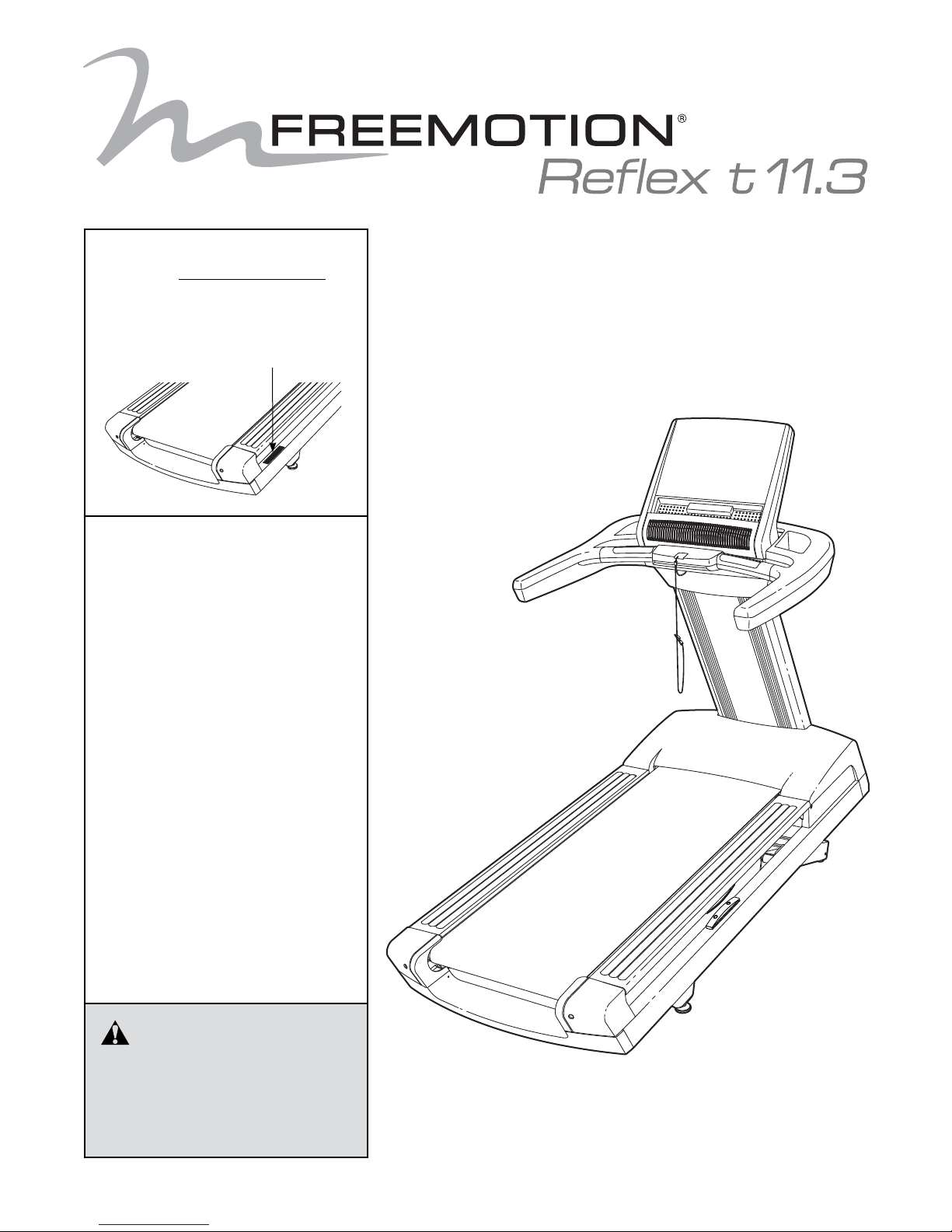
Model No. FMTL39813.2
Serial No.
Write the serial number in the space
above for reference.
Serial Number Decal
QUESTIONS?
If you have questions, or if parts
are damaged or missing,
please see HOW TO CONTACT
CUSTOMER CARE on the back
cover of this manual.
USER’S MANUAL
CAUTION
Read all precautions and instructions in this manual before using
this equipment. Save this manual
for future reference.
www.freemotionfitness.com
Page 2

TABLE OF CONTENTS
WARNING DECAL PLACEMENT . . . . . . . . . . . . . . . . . . . . . . . . . . . . . . . . . . . . . . . . . . . . . . . . . . . . . . . . . . . . . . .3
IMPORTANT PRECAUTIONS ..................................................................4
BEFORE YOU BEGIN. . . . . . . . . . . . . . . . . . . . . . . . . . . . . . . . . . . . . . . . . . . . . . . . . . . . . . . . . . . . . . . . . . . . . . . .6
PART IDENTIFICATION CHART. . . . . . . . . . . . . . . . . . . . . . . . . . . . . . . . . . . . . . . . . . . . . . . . . . . . . . . . . . . . . . . .7
ASSEMBLY . . . . . . . . . . . . . . . . . . . . . . . . . . . . . . . . . . . . . . . . . . . . . . . . . . . . . . . . . . . . . . . . . . . . . . . . . . . . . . . .8
HOW TO USE THE TREADMILL ..............................................................14
HOW TO USE THE CONSOLE . . . . . . . . . . . . . . . . . . . . . . . . . . . . . . . . . . . . . . . . . . . . . . . . . . . . . . . . . . . . . . .15
HOW TO MOVE THE TREADMILL ............................................................19
PREVENTIVE MAINTENANCE. . . . . . . . . . . . . . . . . . . . . . . . . . . . . . . . . . . . . . . . . . . . . . . . . . . . . . . . . . . . . . . .20
SIX-MONTH PREVENTIVE MAINTENANCE RECORD .............................................24
TROUBLESHOOTING ......................................................................25
EXERCISE GUIDELINES ....................................................................27
PART LIST. . . . . . . . . . . . . . . . . . . . . . . . . . . . . . . . . . . . . . . . . . . . . . . . . . . . . . . . . . . . . . . . . . . . . . . . . . . . . . . .30
EXPLODED DRAWING. . . . . . . . . . . . . . . . . . . . . . . . . . . . . . . . . . . . . . . . . . . . . . . . . . . . . . . . . . . . . . . . . . . . . .32
HOW TO CONTACT CUSTOMER CARE . . . . . . . . . . . . . . . . . . . . . . . . . . . . . . . . . . . . . . . . . . . . . . . . Back Cover
LIMITED WARRANTY. . . . . . . . . . . . . . . . . . . . . . . . . . . . . . . . . . . . . . . . . . . . . . . . . . . . . . . . . . . . . . . Back Cover
FREEMOTION is a registered trademark of ICON Health & Fitness, Inc.
2
Page 3
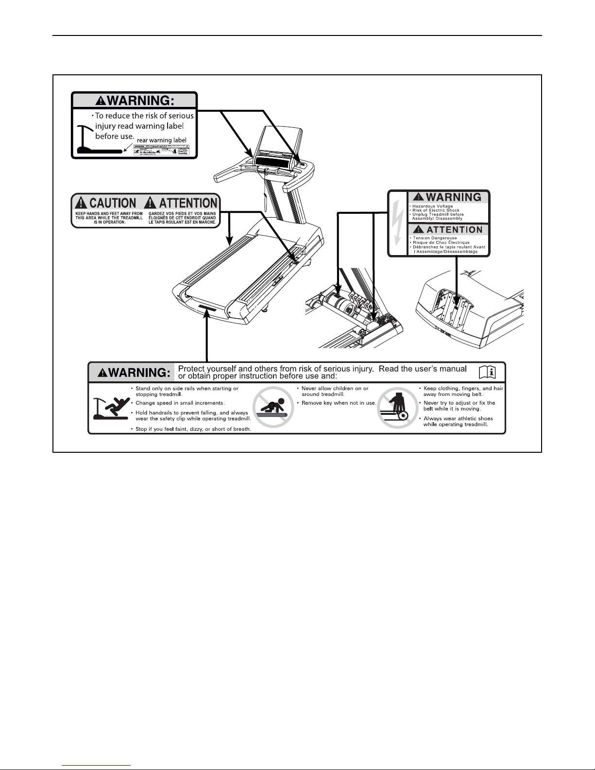
WARNING DECAL PLACEMENT
These drawings show the locations of the
warning decals. If a decal is missing or
illegible, see the back cover of this
manual and request a free replacement
decal. Apply the decal in the location
shown. Note: The decals may not be
shown at actual size.
3
Page 4

IMPORTANT PRECAUTIONS
WARNING: To reduce the risk of burns, re, electric shock, or injury to persons, read
all important precautions and instructions in this manual and all warnings on your treadmill before
using your treadmill. FreeMotion Fitness assumes no responsibility for personal injury or property
damage sustained by or through the use of this product.
1. Before beginning this or any exercise
program, consult your physician. This is
especially important for persons over age 35
or persons with pre-existing health problems.
2. It is the responsibility of the owner to ensure
that all users of this treadmill are adequately
informed of all warnings and precautions.
3. Use the treadmill only as described.
4. Keep the treadmill indoors, away from moisture and dust. Do not put the treadmill in a
garage or covered patio, or near water.
5. Place the treadmill on a level surface, with
at least 8 ft. (2.4 m) of clearance behind it
and 2 ft. (0.6 m) on each side. Do not place
the treadmill on any surface that blocks air
openings. To protect the floor or carpet from
damage, place a mat under the treadmill.
6. Do not operate the treadmill where aerosol
products are used or where oxygen is being
administered.
7. Keep children under age 12 and pets away
from the treadmill at all times.
8. The treadmill should be used only by persons weighing 400 lbs. (181 kg) or less.
9. Never allow more than one person on the
treadmill at a time.
10. Wear appropriate exercise clothes when
using the treadmill. Do not wear loose
clothes that could become caught in the
treadmill. Athletic support clothes are recommended for both men and women. Always
wear athletic shoes. Never use the treadmill
with bare feet, wearing only stockings, or in
sandals.
11. When connecting the power cord, follow the
instructions on page 13. No other appliance
should be on the same circuit as the treadmill.
Do not use an extension cord.
12. Keep the power cord away from heated
surfaces.
13. Never move the walking belt while the power
is turned off. Do not operate the treadmill
if the power cord or plug is damaged, or if
the treadmill is not working properly. (See
TROUBLESHOOTING on page 25 if the treadmill is not working properly.)
14. Read, understand, and test the emergency
stop procedure before using the treadmill (see
HOW TO TURN ON THE POWER on page 16).
15. Never start the treadmill while you are standing on the walking belt. Always hold the
handrails while using the treadmill.
16. The treadmill is capable of high speeds.
Adjust the speed in small increments to
avoid sudden jumps in speed.
17. The heart rate monitor is not a medical
device. Various factors, including the user’s
movement, may affect the accuracy of heart
rate readings. The heart rate monitor is
intended only as an exercise aid in determining heart rate trends in general.
18. Never leave the treadmill unattended while
it is running. Always remove the key, press
the power switch into the off position (see
the drawing on page 6 for the location of the
power switch), and unplug the power cord
when the treadmill is not in use.
4
Page 5

19. Do not attempt to move the treadmill until it
is properly assembled. (See ASSEMBLY on
page 8, and HOW TO MOVE THE TREADMILL
on page 19.) You must be able to safely lift 45
lbs. (20 kg) to move the treadmill.
20. Do not change the incline of the treadmill by
placing objects under the treadmill.
the treadmill, and before performing the
maintenance and adjustment procedures
described in this manual. Never remove the
motor hood unless instructed to do so by an
authorized service representative. Servicing
other than the procedures in this manual
should be performed by an authorized service representative only.
21. Inspect and properly tighten all parts of the
treadmill regularly.
22. Never insert or drop any object into any
opening on the treadmill.
23. DANGER: Always unplug the power
cord immediately after use, before cleaning
SAVE THESE INSTRUCTIONS
24. Over exercising may result in serious injury
or death. If you feel faint or if you experience
pain while exercising, stop immediately and
cool down.
5
Page 6
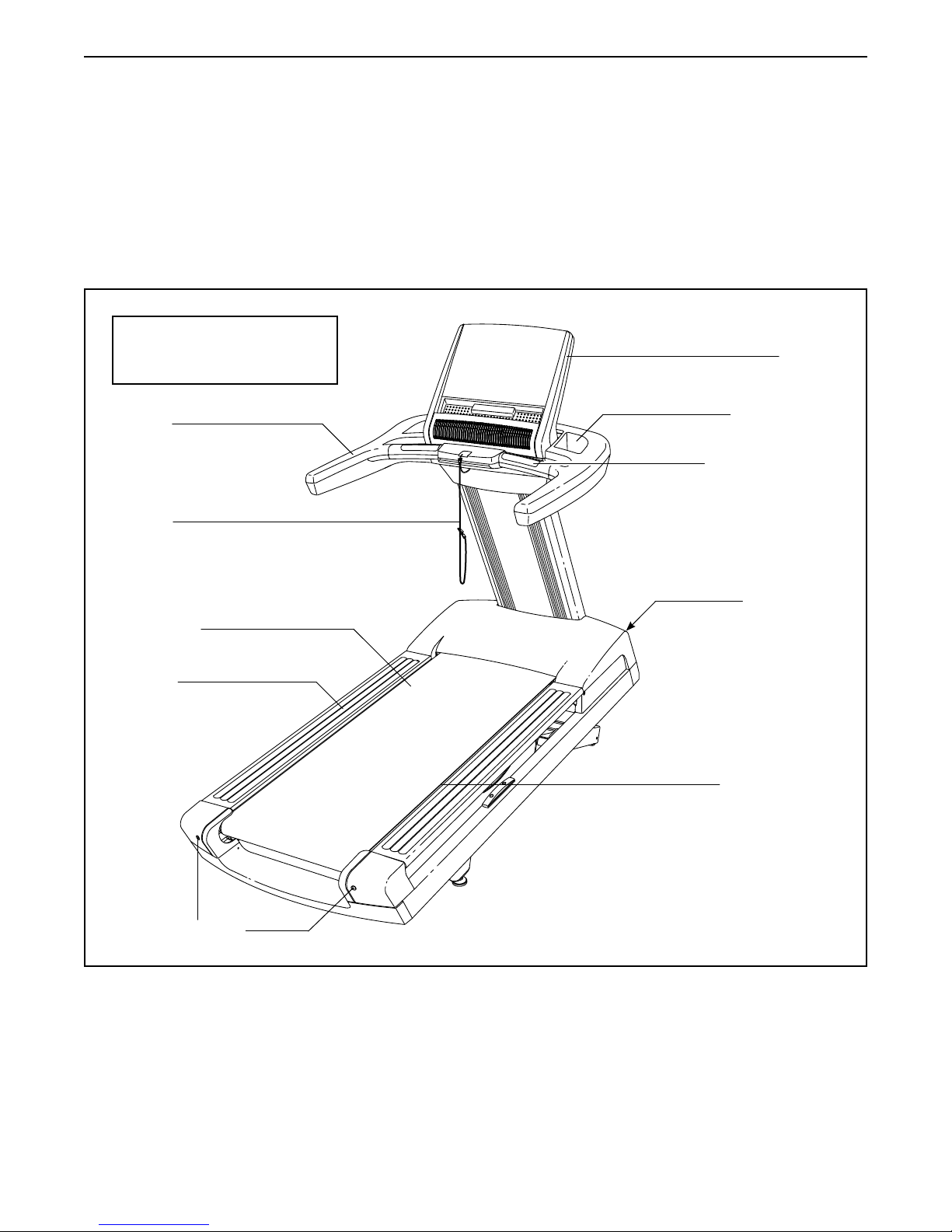
BEFORE YOU BEGIN
Thank you for selecting the revolutionary
FREEMOTION® REFLEX T 11.3 treadmill. The
REFLEX T 11.3 treadmill offers an impressive selection of features designed to make your workouts more
enjoyable and effective.
For your benet, read this manual carefully before
using the treadmill. If you have questions after
Length: 7 ft. 2 in. (218 cm)
Width: 2 ft. 10 in. (86 cm)
Handrail
Key/Clip
reading this manual, please see the back cover of this
manual. To help us assist you, note the product model
number and serial number before contacting us. The
model number and the location of the serial number
decal are shown on the front cover of this manual.
Before reading further, please review the drawing
below and familiarize yourself with the labeled parts.
Console
Accessory Tray
Heart Rate Monitor
Walking Belt
Foot Rail
Idler Roller
Adjustment Screws
Power Switch
Walking Platform
6
Page 7
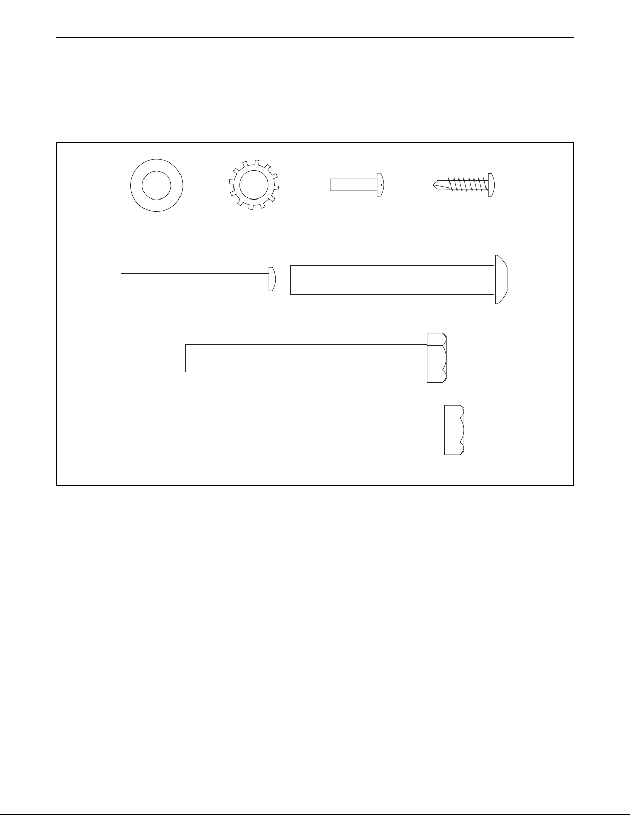
PART IDENTIFICATION CHART
Use the drawings below to identify small parts used for assembly. The number in parentheses below each drawing is the key number of the part, from the PART LIST near the end of this manual. The number following the key
number is the quantity used for assembly. Note: If a part is not in the hardware kit, check to see whether it is
preattached. Extra hardware may be included.
3/8" Flat
Washer (43)–5
#8 x 2" Screw
(106)–4
3/8" Star
Washer (2)–7
3/8" x 3 1/4" Screw (1)–6
3/8" x 3 3/4" Screw (11)–4
#8 x 5/8"
Screw (18)–2
3/8" x 2 3/4" Screw (27)–4
#8 x 3/4" Tek Screw
(28)–4
7
Page 8
ASSEMBLY
• Assembly requires two persons.
• Place all parts in a cleared area and remove the
packing materials. Do not dispose of the packing
materials until you nish all assembly steps.
• To identify small parts, see page 7.
• After shipping, there may be an oily substance
on the exterior of the treadmill. This is normal. If
there is an oily substance on the treadmill, wipe
it off with a soft cloth and a mild, non-abrasive
cleaner.
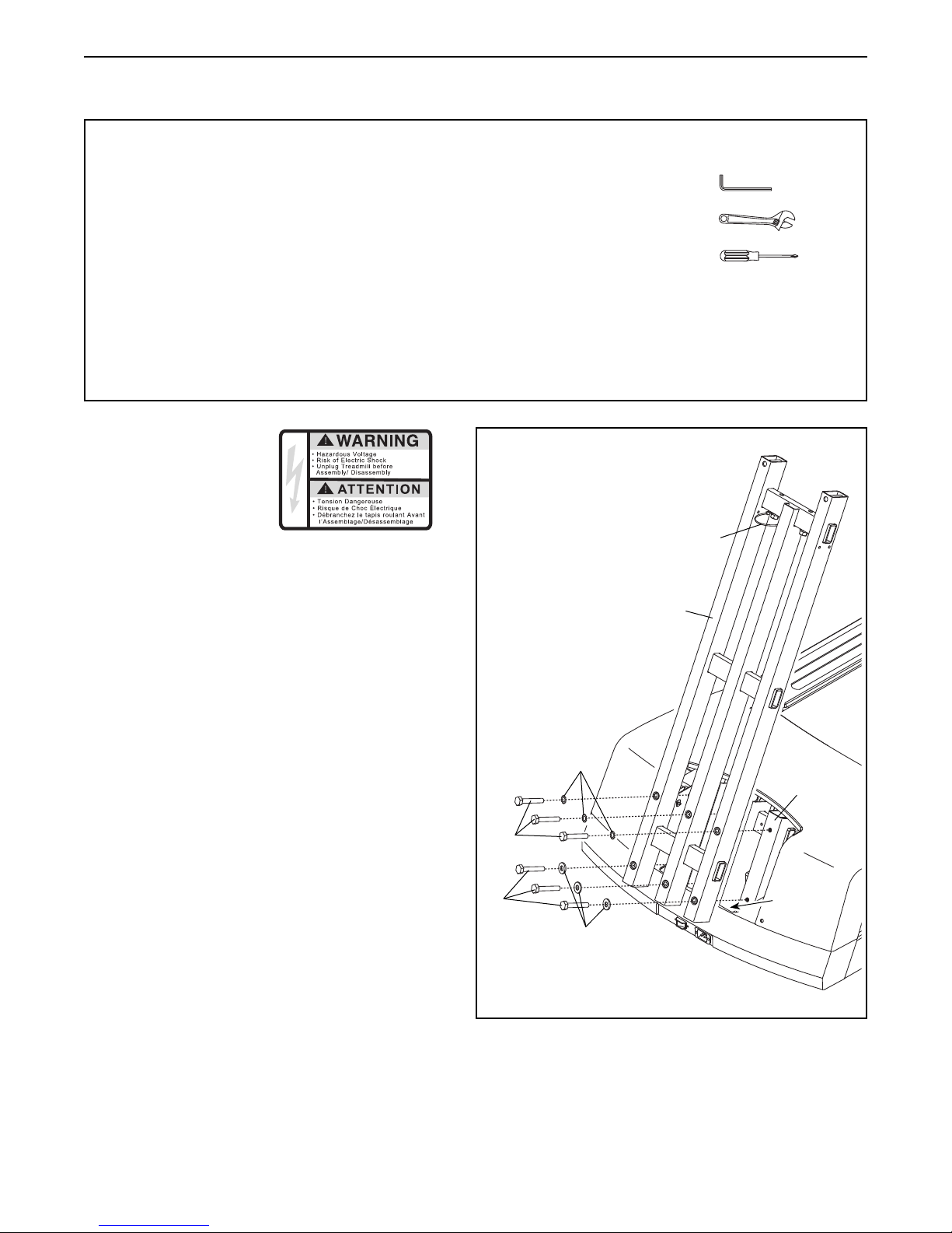
1. Make sure that
the power cord
is unplugged. Be
careful not to pinch
the power cord.
Slide the Upright Cover (not shown) off the
Upright (81).
• Assembly requires the following tools:
the included hex key
one adjustable wrench
one Phillips screwdriver
To avoid damaging parts, do not use power tools.
1
Plastic Ties
Orient the Upright (81) and the plastic ties as
shown. Set the Upright on the tabs on the Frame
(53). Then, attach the Upright with six 3/8" x 3
1/4" Screws (1), three 3/8" Star Washers (2),
and three 3/8" Flat Washers (43). Start all six
Screws, and then tighten them. Make sure
not to pinch any wires.
81
2
53
1
1
43
Tabs
8
Page 9
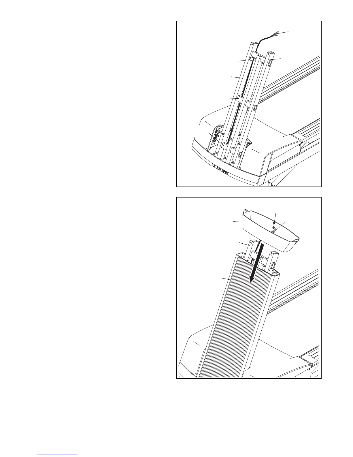
2. Insert the end of the Upright Wire (111) through
the looped plastic tie at the top of the Upright
(81). Make sure that the Upright Wire is
behind the crossbars on the Upright. Then,
gently pull upward on the Upright Wire as you
tighten the plastic ties around the Upright Wire.
2
Crossbar
Plastic Ties
Crossbar
111
Crossbar
81
3. Slide the Upright Cover (80) downward onto
the Upright (81). Make sure not to pinch the
Upright Wire (111). Make sure not to hit the
ceiling with the Upright Cover.
Next, orient the Upright Collar (105) so that the
sticker is on the indicated side. Slide the Upright
Collar onto the Upright Cover (80).
3
105
81
80
Sticker
111
9
Page 10
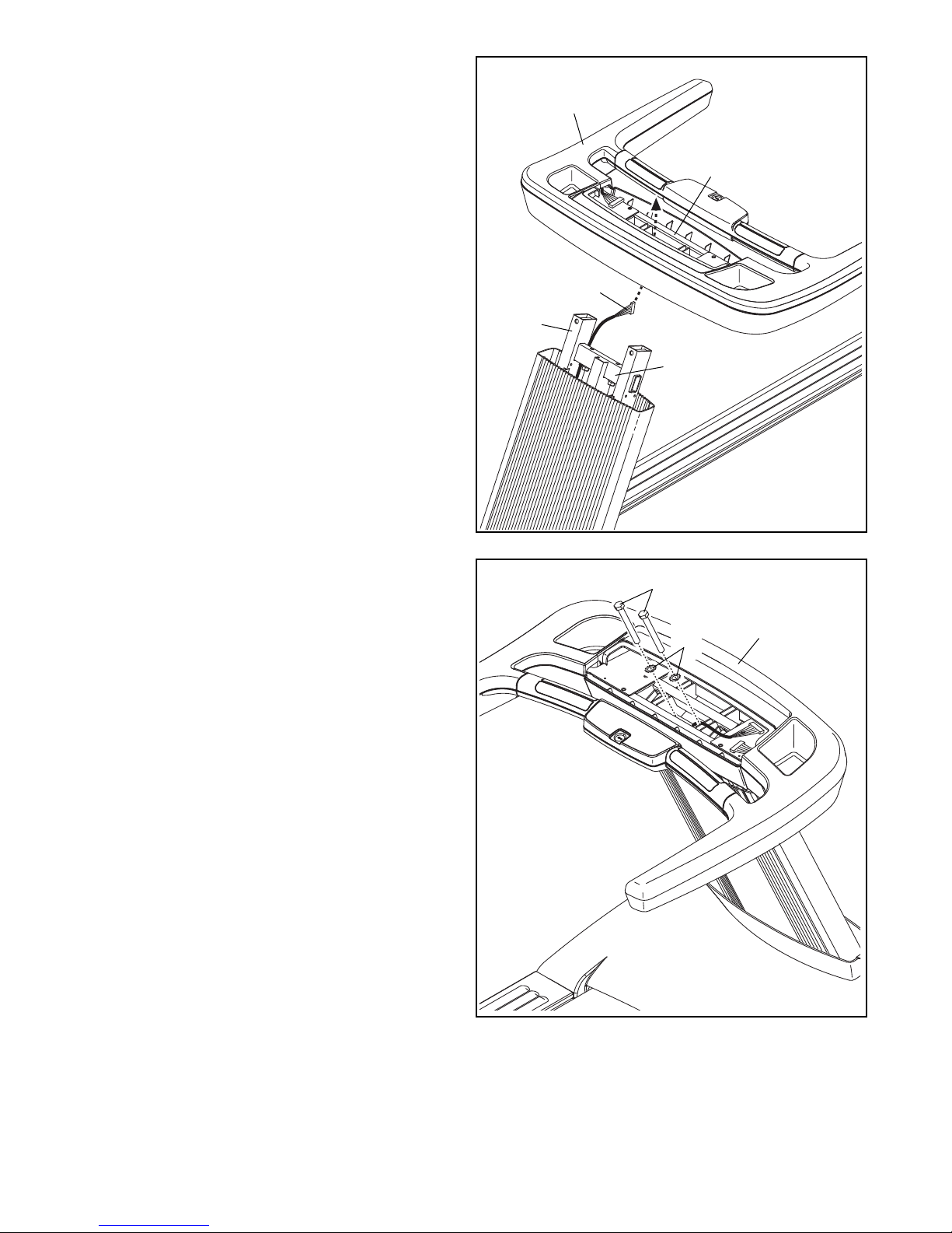
4. Have a second person hold the handrail assembly near the Upright (81). Insert the Upright Wire
(111) upward through the center of the handrail
assembly.
4
Handrail
Assembly
Then, slide the bracket on the handrail assem-
bly over the crossbar on the Upright (81), and
set the handrail assembly on the Upright. Make
sure not to pinch any wires.
5. Attach the handrail assembly with two 3/8" x
3 3/4" Screws (11) and two 3/8" Star Washers
(2). Do not fully tighten the Screws yet. Make
sure not to pinch any wires.
Bracket
111
81
Crossbar
5
11
Handrail
2
Assembly
10
Page 11
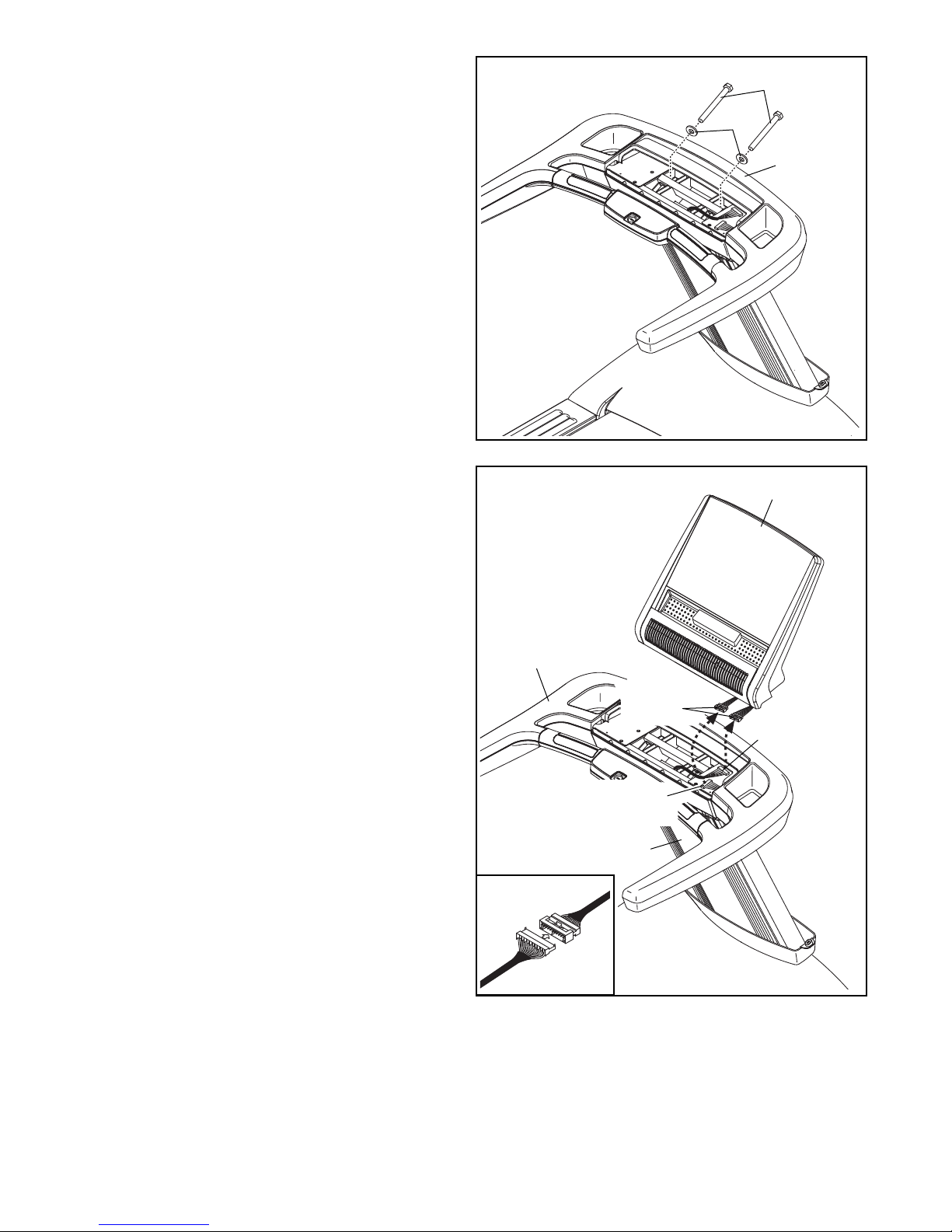
6. Tighten two 3/8" x 3 3/4" Screws (11) with two
3/8" Flat Washers (43) into the handrail assembly. Start both Screws, and then tighten them.
See step 5. Tighten the two 3/8" x 3 3/4"
Screws (11).
6
11
43
Handrail
Assembly
7. Have a second person hold the Console
Assembly (101) near the handrail assembly.
See the inset drawing. Connect the Upright
Wire (111) and the handrail wire to the console
wires. Make sure that the console wire and
the handrail wire that you are connecting have
connectors that are the same size. The connec-
tors should slide together easily and snap
into place. If they do not, turn one connector
and then try again. IF THE CONNECTORS
ARE NOT CONNECTED PROPERLY, THE
CONSOLE MAY BE DAMAGED WHEN THE
POWER IS TURNED ON.
Next, insert the excess wires downward into the
Upright Cover (80).
Then, set the Console Assembly (101) on the
handrail assembly. Make sure not to pinch any
wires.
7
Handrail
Assembly
101
Console
Wires
111
Handrail
Wire
80
11
Page 12

8. Tighten four 3/8" x 2 3/4" Screws (27) with two
3/8" Star Washers (2) into the handrail assembly.
8
Handrail
Assembly
27
2
2
27
9. Attach the Upright Collar (105) to the handrail
assembly with two #8 x 5/8" Screws (18).
10. With the help of second person, carefully tip the
treadmill onto one side. Remove any packing
materials from the bottom of the Frame (53).
Next, attach the two Rear Foot Covers (91)
to the Frame (53) with the four #8 x 3/4" Tek
Screws (28).
9
Handrail
Assembly
105
18
10
53
18
91
64
28
Then, fully thread the two Leveling Feet (64) into
the bottom of the Frame (53).
Carefully tip the treadmill back to the upright
position.
91
64
28
12
Page 13

11. If necessary, move the treadmill to the desired
location (see HOW TO MOVE THE TREADMILL
on page 19).
After the treadmill is placed in the location where
it will be used, make sure that the Leveling Feet
(64) rest firmly on the floor. If the treadmill rocks
even slightly, turn the nut on the Leveling Foot
clockwise or counterclockwise until the rocking
motion is eliminated.
11
64
12. Cut the tie holding the Power Cord (70) to the
Power Cord Cover (112).
Plug the Power Cord (70) into the treadmill.
Attach the Power Cord Cover (112) with four #8
x 2" Screws (106).
13. Make sure that all parts are properly tightened before you use the treadmill. If there are sheets of plastic
on the treadmill decals, remove the plastic. To protect the floor or carpet, place a mat under the treadmill. To
avoid damage to the console, keep the treadmill out of direct sunlight. Keep the included hex key in a secure
place; the hex key is used to adjust the walking belt (see pages 25 and 26). Note: Extra hardware may be
included.
12
112
70
106
106
13
Page 14

HOW TO USE THE TREADMILL
182993
WARRANTY INFORMATION
DANGER: Improper connec-
tion of the equipment-grounding conductor
increases the risk of electric shock. Check
with a qualied electrician or serviceman if
you are unsure whether the product is properly grounded. Do not modify the plug—if
it will not t the outlet, have a proper outlet
installed by a qualied electrician. Do not use
an adapter to connect the plug to an improper
receptacle.
HOW TO CONNECT THE POWER CORD
This product must be grounded. If it should mal-
function or break down, grounding provides a path of
least resistance for electric current to reduce the risk of
electric shock.
This product is for use on a dedicated, 20-amp,
120-volt circuit. No other appliance should be on
the same circuit. This product has a cord with an
equipment-grounding conductor and a grounding plug.
The warranty for this product does not cover damage
or equipment failure caused by electric wiring not in
compliance with electrical codes or the specications
in this manual, or failure to provide reasonable and
necessary maintenance as outlined in this manual.
Any failure or damage caused by unauthorized service;
misuse; accident; negligence; improper assembly or
installation; debris resulting from any destruction activi-
ties in the product’s environment; rust or corrosion as a
result of the product’s location; alterations or modica-
tions without written authorization; or failure on your
part to use, operate, and maintain the product as set
forth in this manual will void the warranty.
All terms of the warranty are void if this product
is moved beyond the continental borders of the
United States of America (excluding Alaska, Hawaii,
and Canada) and are then subject to the terms provided by that country’s local authorized FreeMotion
Fitness, Inc. representative.
Plug the grounding plug into a standard NEMA 5-20
receptacle. Do not modify the plug or the receptacle.
Do not use an adapter, a surge protector, or an extension cord. The receptacle must be grounded.
NEMA 5-20
Receptacle
14
Page 15

HOW TO USE THE CONSOLE
FEATURES OF THE CONSOLE
The treadmill console offers an impressive array of
features designed to make your workouts more effective and enjoyable. You can change the speed and
incline of the treadmill with the touch of a button. As
you exercise, the console will display instant exercise
feedback. You can even measure your heart rate using
the handgrip heart rate monitor.
To turn on the power, see page 16. To use the
manual mode, see page 16. To use the maintenance
mode, see page 18.
Note: The console can display speed and distance in
either miles or kilometers. To nd which unit of measurement is selected, see THE MAINTENANCE MODE
on page 18. For simplicity, all instructions in this
manual refer to miles.
IMPORTANT: If there are sheets of plastic on the
console, remove the plastic. To prevent damage
to the walking platform, wear clean athletic shoes
while using the treadmill. The rst time you use
the treadmill, observe the alignment of the walking
belt, and center the walking belt if necessary (see
page 26).
15
Page 16

HOW TO TURN ON THE POWER
HOW TO USE THE MANUAL MODE
IMPORTANT: If the treadmill has been exposed to
cold temperatures, allow it to warm to room temperature before turning on the power. If you do not
do this, you may damage the console displays or
other electrical components.
Plug in the power cord
(see page 14). Next,
locate the power switch
on the treadmill frame
near the power cord.
Press the power switch
into the on position.
IMPORTANT: The console features a display demo
mode, designed to be used if the treadmill is displayed in a store. If the displays light as soon as
you plug in the power cord and press the power
switch into the reset position, the demo mode is
turned on. To turn off the demo mode, hold down
the Stop button for a few seconds. If the displays
remain lit, see THE MAINTENANCE MODE on page
18 to turn off the demo mode.
Next, stand on the foot rails
of the treadmill. Find the clip
attached to the key and slide
the clip onto the waistband of
your clothes. Then, insert the
key into the console. After
a moment, the displays will
light. IMPORTANT: In an
emergency, the key can be pulled from the console,
causing the walking belt to slow to a stop. Test the
clip by carefully taking a few steps backward; if the
key is not pulled from the console, adjust the position of the clip.
On
Key
Clip
1. Insert the key into the console.
See HOW TO TURN ON THE POWER at the left.
2. Enter your age and weight if desired.
To enter your age, press the Age increase and
decrease buttons. To enter your weight, press the
Wt. increase and decrease buttons.
3. Start the walking belt.
To start the walking belt, press the Start button, the
Speed increase button, or one of the numbered
Speed buttons.
If you press the Start button or the Speed increase
button, the walking belt will begin to move at 1 mph.
As you exercise, change the speed of the walking
belt as desired by pressing the Speed increase
and decrease buttons. Each time you press one of
the buttons, the speed setting will change by 0.1
mph; if you hold down the button, the speed setting
will change in increments of 0.5 mph. Note: After
you press the button, it may take a moment for the
walking belt to reach the selected speed setting.
If you press one of the numbered Speed buttons,
the walking belt will gradually change speed until
it reaches the selected speed setting. To select a
speed setting that includes a decimal—such as 3.5
mph—press two numbered buttons in succession.
For example, to select a speed setting of 3.5 mph,
press the 3 button and then immediately press the
5 button.
To stop the walking belt, press the Stop button. The
time will begin to ash in the display. To restart the
walking belt, press the Start button or the Speed
increase button.
4. Change the incline of the treadmill as desired.
To change the incline of the treadmill, press the
Incline increase or decrease button or one of the
numbered Incline buttons. Each time you press one
of the buttons, the treadmill will gradually adjust to
the selected incline setting.
16
Page 17

5. Follow your progress with the displays.
6. Measure your heart rate if desired.
The matrix—
The matrix will
display a track that
represents 1/4 mile
(400 meters). As you
exercise, the indicators
around the track will appear in succession until the
entire track appears. The track will then disappear
and the indicators will again begin to appear in
succession.
The Incline display—This display will show the
incline of the treadmill.
The Time display—This display will show the
elapsed time.
The Distance display—This display will show the
distance that you have walked or run.
The Speed display—This display will show the
speed of the walking belt.
The Calories display—This display will show the
approximate number of calories you have burned.
The Pulse display—This display will show your
heart rate when you use the handgrip pulse sensor
(see step 6).
The Pace display—This display will show your
pace.
To reset the displays, press the Stop button, re-
move the key, and then reinsert the key. Note: If
the treadmill is not used for a few minutes, the displays will reset automatically.
Before using the handgrip heart rate monitor, re-
move the sheets of plastic from the metal contacts
on the pulse bar. In addition, make sure that your
hands are clean.
To measure
your heart rate,
stand on the
foot rails and
hold the pulse
bar with your
palms on the
metal contacts;
avoid moving
your hands.
When your
pulse is detected, several dashes will appear and
then your heart rate will be shown. For the most
accurate heart rate reading, continue to hold
the contacts for about 15 seconds.
7. Turn on the fan if desired.
The fan features several
speed settings and an
auto mode. When the
auto mode is selected, the
speed of the fan will automatically increase and decrease as the speed of
the walking belt increases and decreases.
Press the fan increase or decrease button to select
a fan speed or to turn off the fan. Note: If the fan
is on when the walking belt is stopped, the fan will
turn off automatically after a few minutes.
8. Step onto the foot rails, press the Stop button, and
adjust the incline of the treadmill to zero.
Contacts
17
Page 18

THE MAINTENANCE MODE
The console features a maintenance mode that keeps
track of treadmill information and allows you to personalize console settings.
TOT TIME—This display will show the total number of
hours that the treadmill has been used.
TOT DIST—This display will show the total number of
miles or kilometers that have been run on the machine.
To select the maintenance mode, hold down the
Stop button while inserting the key into the console,
and then release the Stop button. When the maintenance mode is selected, press the Age increase and
decrease buttons to access the optional screens.
Then, press the Wt. increase and decrease buttons to
change settings.
UNITS—This display will show which unit of measurement is selected. To view distance in miles, select
UNITS ENGLISH. To view distance in kilometers,
select UNITS METRIC.
PAUSE TIME—This display allows you to adjust the
amount of time that will pass before the console will
reset the displays after the walking belt has been
paused.
IDLE TIME—This display allows you to adjust the
amount of time that will pass before the console goes
to sleep after no buttons have been pressed.
BELT DIST—This display will show the total number of
miles or kilometers that the walking belt has moved.
RESET BELT—This display is used to reset the belt
distance after the walking belt is changed.
CONTRAST—This display allows you to adjust the
contrast level of the console.
CALIBRATE INCL—This display is used to calibrate
the incline system. To calibrate the incline system,
press the Wt. increase and decrease buttons.
Note: There are several other optional screens in the
maintenance mode meant to provide information about
your machine to service technicians.
To exit the maintenance mode, remove the key from
the console.
18
Page 19

HOW TO MOVE THE TREADMILL
Due to the size and weight of the treadmill, moving
it requires two or three persons.
Before moving the treadmill, plug in the power cord
and insert the key into the console (see HOW TO
TURN ON THE POWER on page 16). Raise the incline
to the highest position. Then, remove the key and
unplug the power cord.
1. Hold the handle firmly in the location shown
below. CAUTION: To decrease the possibility of
damage to the treadmill or of injury, do not lift
the treadmill by the handrail. Raise the handle
until the treadmill rolls freely on the wheels. Then,
carefully roll the treadmill to the desired location,
and lower it to the level position. CAUTION: To
reduce the risk of injury, use extreme caution
while moving the treadmill. Do not attempt to
move the treadmill over uneven surfaces.
1
2. After the treadmill is placed in the location where
it will be used, make sure that the leveling feet
rest firmly on the floor. If the treadmill rocks even
slightly, turn the nut on the leveling foot clockwise
or counterclockwise until the rocking motion is
eliminated.
2
Leveling Feet
Handle
Wheels
19
Page 20

PREVENTIVE MAINTENANCE
Regular maintenance is necessary for optimal performance and long life of the treadmill. Please read and
follow all instructions below. If the treadmill is not
maintained as described, components may wear
excessively, the treadmill may become damaged,
and the warranty will be voided. If you have ques-
tions about maintenance, see the back cover of this
manual. CAUTION: Make sure to remove the key
and unplug the power cord before performing any
maintenance procedures.
WEEKLY MAINTENANCE
1. Unplug the power cord. Inspect and properly
tighten all external parts of the treadmill.
2. Apply a mild multi-purpose cleaner to a 100%
cotton cloth and remove any dust and grime from
the handrails, upright, foot rails, frame, and motor
hood. In addition, wipe the walking platform along
the sides of the walking belt. Do not wipe under
the walking belt. Apply a small amount of mild
multi-purpose cleaner to a 100% cotton cloth and
wipe the console and the screen(s). Do not spray
cleaner directly onto the treadmill or use ammonia or acid-based cleaners.
2. Using a handheld vacuum, clean the area under
the Motor Hood (not shown). Be careful to avoid
touching any components. Then, check the Motor
Belt (57) for wear and cracks. If the Motor Belt needs
to be replaced, see the back cover of this manual.
2
3. Plug in the power cord and insert the key into the
console. Then, press the Start button. Be care-
ful to avoid injury; keep your hands away from
moving parts and make sure that your clothes
cannot become caught in moving parts. While
the walking belt is moving, check the treadmill for
unusual noises or odors. If any of these problems
exists, see the back cover of this manual.
57
3. Make sure that the walking belt is centered and
properly tightened. If it is centered and runs
smoothly, do not make any adjustments. If the walking belt needs to be adjusted, see pages 23 and 26.
MONTHLY MAINTENANCE
1. Unplug the power cord. Remove the four 5/16"
x 1/2" Screws (16) attaching the Motor Hood (66),
and lift off the Motor Hood.
1
66
16
16
16
Remove the key and unplug the power cord. See
step 1. Reattach the Motor Hood (66) with the 5/16"
x 1/2" Screws (16).
20
Page 21

REPLACING THE WALKING PLATFORM AND THE
WALKING BELT
Inspect the walking platform periodically for wear. If
there is any wood showing through the phenolic coating, or if the surface is damaged, the walking platform
should be replaced. When the walking belt becomes
worn, it should be replaced. The walking platform and
the walking belt should be replaced after every 10,000
to 15,000 miles (16,000 to 24,000 kilometers). Follow
the instructions below to replace the walking platform
and/or the walking belt. Make sure to keep track of
which holes the screws go in.
1. Remove the key and unplug the power cord.
Remove the four 5/16" x 1/2" Screws (16) and the
Motor Hood (66).
1
16
3. Remove the two 1/4" x 3/4" Bolts (9), the two 5/16"
x 1 1/2" Bolts (8), the two 3/8" Washers (32), and
the two 5/16" Locknuts (38).
Remove the two 3/8" x 2 1/2" Screws (7), the two
3/8" Lock Washers (not shown), and the two 3/8"
Flat Washers (not shown).
Remove the 1/4" x 2 1/2" Screw (85) and the 1/4"
Star Washer (89). Then, remove the Idler Roller
(63) and the Drive Roller (113).
If you are replacing the Walking Platform (44),
go to step 4.
If you are replacing only the Walking Belt (46),
remove the Walking Belt and slide the new Walking
Belt onto the Walking Platform (44). Then, follow
steps 1–3 in reverse order. Turn both 3/8" x 2 1/2"
Screws (7) clockwise four times only. Go to step 5.
66
16
2. Remove the four indicated 1/4" x 3/4" Bolts (9) and
the two M4 x 13mm Screws (138). Then, remove
the Rear Cap (59).
2
138
138
9
59
9
16
3
38
32
38
8
7
63
7
46
44
32
8
9
85
89
113
9
21
Page 22

4. Remove the Walking Belt (46) and the Walking
Platform (44) from the treadmill. Next, remove the
Walking Belt from the Walking Platform. Then,
remove the twelve 3/8" x 1 1/2" Bolts (5) and the
twelve 3/8" Locknuts (34), and slide the Rear and
Front Platform Brackets (47, 48) off the Walking
Platform. Remove and save the four #16 x 1 1/2"
Screws (147) and the two Platform Cushions (146).
Slide the Rear and Front Platform Brackets (47, 48)
onto the new Walking Platform (44).
Follow steps 1–4 in reverse order. If you are replac-
ing the Walking Belt (46), use the new Walking
Belt. Turn the 3/8" x 2 1/2" Screws (7) (see step 3)
clockwise four times only. Go to step 5.
4
147
34
44
146
5
146
5
5
48
34
5
5. The tension of the Walking Belt (46) now needs to
be adjusted. Look under the right or left edge of the
Walking Belt and nd the small arrow printed on
the Walking Belt; move the Walking Belt, if necessary, until you nd the arrow. Make sure that the
arrow is pointing toward the rear of the treadmill, as shown. If it is not, remove the Walking
Belt, turn it around, and slide it back onto the
Walking Platform (44). Do not tighten the Walking
Belt yet.
Move the Walking Belt (46), if necessary, until the
seam across the Walking Belt is underneath the
Walking Platform (44).
Using the hex key, turn both idler roller screws
counterclockwise, 1/4 of a turn. Tighten the
Walking Belt (46) until the marks on both sides of
the Walking Belt are exactly 36" apart.
5
46
36"
Arrow
34
47
147
44
46
34
Idler Roller Screws
22
Page 23

6. Center the Walking Belt (46) if necessary (see page
26). Then, plug in the power cord, step onto the
foot rails, insert the key into the console, and press
the Start button. Hold the handrails and gently
press one foot against the moving Walking Belt. If
the Walking Belt stops moving, remove the key
from the console, unplug the power cord, and
turn the two 3/8" x 2 1/2" Screws (7) clockwise one
time. Continue to test the tension of the Walking
Belt until the Walking Belt no longer slips. Make
sure to keep the Walking Belt centered. If the Idler
Roller (63) stops moving, do not further tighten
the Screws; please see the back cover of this
manual.
6
7
46
63
7
23
Page 24

SIX-MONTH PREVENTIVE MAINTENANCE RECORD
Photocopy this form and use it to record the preventive maintenance performed on the treadmill. Each copy of the
form can be used for six months (26 weeks). When maintenance is performed, write the date in the appropriate
spaces. Make sure to perform each maintenance procedure as described on pages 20 to 23. If the pro-
cedures are not performed as described, components may wear excessively, the treadmill may become
damaged, and the warranty will be voided.
Week 1
Week 2
Week 3
Week 4
Week 5
Week 6
Week 7
Week 8
Week 9
Week 10
Week 11
Week 12
Week 13
Week 14
Week 15
Week 16
Week 17
Week 18
Week 19
Week 20
Week 21
Weekly Maintenance
Inspect and
tighten all
external parts
of the treadmill.
/ / / /
/ /
/ / / /
/ / / /
/ / / /
/ / / /
/ / / /
/ / / /
/ / / /
/ / / /
/ / / /
/ / / /
/ / / /
/ / / /
/ / / /
/ / / /
/ / / /
/ / / /
/ / / /
/ / / /
/ / / /
Clean the
treadmill.
/ /
Check the
walking belt for
proper tension
and alignment.
/ /
/ /
/ /
/ /
/ /
/ /
/ /
/ /
/ /
/ /
/ /
/ /
/ /
/ /
/ /
/ /
/ /
/ /
/ /
/ /
/ /
Monthly Maintenance
Remove the
motor hood
and vacuum
the motor
compartment.
Check the
motor belt for
cracks and
other wear.
/ / / / / /
/ / / / / /
/ / / / / /
/ / / /
/ / / / / /
Check the
motor for arcing; check for
noises or odors.
/ /
Week 22
Week 23
Week 24
Week 25
Week 26
/ / / /
/ / / /
/ / / /
/ / / /
/ / / /
Walking Platform Replaced Walking Belt Replaced
/ /
/ /
/ /
/ /
/ /
/ /
/ / / / / /
/ / / /
24
Page 25

TROUBLESHOOTING
Most treadmill problems can be solved by following
the simple steps below. Find the symptom that
applies, and follow the steps listed. If further assistance is needed, see the back cover of this manual.
SYMPTOM: The power does not turn on
a. Make sure that the power cord is plugged into a
properly grounded outlet (see page 14).
b. After the power cord has been plugged in, make
sure that the key is inserted into the console.
c. Check the power
switch located on
the treadmill near
the power cord.
Make sure that the
power switch is
pressed into the on
position.
c
On
SYMPTOM: The power turns off during use
a. Check the power switch (see the drawing c at the
left). If the switch has tripped, wait for five minutes
and then press the switch to the on position.
b. Make sure that the power cord is plugged in. If the
power cord is plugged in, unplug it, wait for five
minutes, and then plug it back in.
c. Remove the key from the console, and then
reinsert it.
d. If the treadmill still will not run, please see the back
cover of this manual.
SYMPTOM: The incline of the treadmill does not
change correctly
a. Calibrate the incline system (see THE
MAINTENANCE MODE on page 18).
25
Page 26

SYMPTOM: The walking belt is off-center or slips
when walked on
a. If the walking belt is off-center, first remove the
key and UNPLUG THE POWER CORD. If the
walking belt has shifted to the left, use the hex
key to turn the left idler roller screw clockwise 1/2
of a turn; if the walking belt has shifted to the
right, turn the left idler roller screw counterclockwise 1/2 of a turn. Be careful not to overtighten the
walking belt. Then, plug in the power cord, insert
the key, and run the treadmill for a few minutes.
Repeat until the walking belt is centered.
a
b. If the walking belt slips when walked on, first
remove the key and UNPLUG THE POWER
CORD. Using the hex key, turn both idler roller
screws clockwise, 1/4 of a turn. To properly tighten
the treadmill, see step 5 on page 22. Be careful to
keep the walking belt centered. Then, plug in the
power cord, insert the key, and carefully walk on
the treadmill for a few minutes. Repeat until the
walking belt is properly tightened.
b
26
Page 27

EXERCISE GUIDELINES
WARNING: Before beginning this
or any exercise program, consult your physician. This is especially important for persons
over age 35 or persons with pre-existing
health problems.
The heart rate monitor is not a medical device.
Various factors may affect the accuracy of
heart rate readings. The heart rate monitor is
intended only as an exercise aid in determining heart rate trends in general.
These guidelines will help you to plan your exercise
program. For detailed exercise information, obtain a
reputable book or consult your physician. Remember,
proper nutrition and adequate rest are essential for
successful results.
EXERCISE INTENSITY
Whether your goal is to burn fat or to strengthen your
cardiovascular system, exercising at the proper intensity is the key to achieving results. You can use your
heart rate as a guide to find the proper intensity level.
The chart below shows recommended heart rates for
fat burning and aerobic exercise.
Burning Fat—To burn fat effectively, you must exercise at a low intensity level for a sustained period of
time. During the first few minutes of exercise, your
body uses carbohydrate calories for energy. Only after
the first few minutes of exercise does your body begin
to use stored fat calories for energy. If your goal is to
burn fat, adjust the intensity of your exercise until your
heart rate is near the lowest number in your training
zone. For maximum fat burning, exercise with your
heart rate near the middle number in your training
zone.
Aerobic Exercise—If your goal is to strengthen your
cardiovascular system, you must perform aerobic
exercise, which is activity that requires large amounts
of oxygen for prolonged periods of time. For aerobic
exercise, adjust the intensity of your exercise until your
heart rate is near the highest number in your training
zone.
WORKOUT GUIDELINES
Warming Up—Start with 5 to 10 minutes of stretch-
ing and light exercise. A warm-up increases your body
temperature, heart rate, and circulation in preparation
for exercise.
Training Zone Exercise—Exercise for 20 to 30 minutes with your heart rate in your training zone. (During
the first few weeks of your exercise program, do not
keep your heart rate in your training zone for longer
than 20 minutes.) Breathe regularly and deeply as you
exercise; never hold your breath.
To find the proper intensity level, find your age at the
bottom of the chart (ages are rounded off to the nearest ten years). The three numbers listed above your
age define your “training zone.” The lowest number is
the heart rate for fat burning, the middle number is the
heart rate for maximum fat burning, and the highest
number is the heart rate for aerobic exercise.
Cooling Down—Finish with 5 to 10 minutes of stretching. Stretching increases the flexibility of your muscles
and helps to prevent post-exercise problems.
EXERCISE FREQUENCY
To maintain or improve your condition, complete three
workouts each week, with at least one day of rest
between workouts. After a few months of regular exercise, you may complete up to five workouts each week,
if desired. Remember, the key to success is to make
exercise a regular and enjoyable part of your everyday
life.
27
Page 28

SUGGESTED STRETCHES
The correct form for several basic stretches is shown at the right. Move slowly as you stretch —never bounce.
1. Toe Touch Stretch
Stand with your knees bent slightly and slowly bend forward from
your hips. Allow your back and shoulders to relax as you reach down
toward your toes as far as possible. Hold for 15 counts, then relax.
Repeat 3 times. Stretches: Hamstrings, back of knees and back.
2. Hamstring Stretch
1
Sit with one leg extended. Bring the sole of the opposite foot toward
you and rest it against the inner thigh of your extended leg. Reach
toward your toes as far as possible. Hold for 15 counts, then relax.
Repeat 3 times for each leg. Stretches: Hamstrings, lower back and
groin.
3. Calf/Achilles Stretch
With one leg in front of the other, reach forward and place your hands
against a wall. Keep your back leg straight and your back foot flat on
the floor. Bend your front leg, lean forward and move your hips toward
the wall. Hold for 15 counts, then relax. Repeat 3 times for each leg.
To cause further stretching of the achilles tendons, bend your back leg
as well. Stretches: Calves, achilles tendons and ankles.
4. Quadriceps Stretch
With one hand against a wall for balance, reach back and grasp one
foot with your other hand. Bring your heel as close to your buttocks as
possible. Hold for 15 counts, then relax. Repeat 3 times for each leg.
Stretches: Quadriceps and hip muscles.
5. Inner Thigh Stretch
Sit with the soles of your feet together and your knees outward. Pull
your feet toward your groin area as far as possible. Hold for 15 counts,
then relax. Repeat 3 times. Stretches: Quadriceps and hip muscles.
2
3
4
5
28
Page 29

NOTES
29
Page 30

PART LIST
Key No. Qty. Description Key No. Qty. Description
Model No. FMTL39813.2 R0115A
1 6 3/8" x 3 1/4" Screw
2 8 3/8" Star Washer
3 2 #8 x 5/8" Machine Screw
4 1 #8 x 3/4" Ground Screw
5 12 3/8" x 1 1/2" Bolt
6 2 3/8" x 2 1/2" Bolt
7 2 3/8" x 2 1/2" Screw
8 6 5/16" x 1 1/2" Bolt
9 10 1/4" x 3/4" Bolt
10 4 1/4" x 1" Screw
11 4 3/8" x 3 3/4" Screw
12 2 1/4" x 1/2" Screw
13 2 1/2" x 3 1/2" Screw
14 1 1/2" x 1 5/8" Bolt
15 1 1/2" x 2 1/2" Bolt
16 4 5/16" x 1/2" Screw
17 5 #8 x 1/2" Tek Screw
18 10 #8 x 5/8" Screw
19 6 #8 x 2" Screw
20 2 #6 x 3/8" Machine Screw
21 18 #8 x 1/2" Machine Screw
22 2 #10 x 5/16" Machine Screw
23 5 #8 x 1/2" Washer Head Screw
24 18 #8 x 1/2" Screw
25 4 5/16" Standoff
26 4 #8 x 5/8" Machine Screw
27 4 3/8" x 2 3/4" Screw
28 4 #8 x 3/4" Tek Screw
29 4 #10 x 3/4" Screw
30 4 #8 Star Washer
31 12 #4 x 1/4" Screw
32 5 3/8" Washer
33 2 3/8" Lock Washer
34 14 3/8" Locknut
35 2 1/2" Jam Nut
36 4 #10 x 1" Screw
37 2 Cap Clip
38 2 5/16" Locknut
39 4 5/16" Flat Washer
40 4 1/4" Nut
41 1 Speed Disk
42 2 #8 Nut
43 5 3/8" Flat Washer
44 1 Walking Platform
45 2 Belt Guide
46 1 Walking Belt
47 1 Rear Platform Bracket
48 1 Front Platform Bracket
49 2 Platform Cushion
50 1 Reed Switch Bracket
51 1 Reed Switch
52 1 Controller
53 1 Frame
54 1 Drive Motor
55 4 Motor Bushing
56 1 Motor Mounting Plate
57 1 Motor Belt
58 1 Left Rear Cap Insert
59 1 Rear Cap
60 1 Left Cap Insert Bracket
61 1 Right Rear Cap Insert
62 2 Rear Platform Bracket Bearing
63 1 Idler Roller
64 2 Leveling Foot
65 1 Grommet
66 1 Motor Hood
67 1 Front Cap
68 1 Electronics Bracket
69 1 Power Switch
70 1 Power Cord
71 1 Receptical
72 1 Left Side Cover
73 1 Right Side Cover
74 2 Hood Bracket
75 1 Roller Cover
76 1 Incline Motor
77 2 Front Wheel
78 1 Lift Frame
79 4 Lift Frame Spacer
80 1 Upright Cover
81 1 Upright
82 1 Bottom Handrail Cover
83 1 Handrail Frame
84 4 #10 Star Washer
85 1 1/4" x 2 1/2" Screw
86 1 Handrail Cover
87 1 Pulse Assembly
88 1 Pulse Bar Crossbar
89 1 1/4" Star Washer
90 2 1/4" Jam Nut
91 2 Rear Foot Cover
92 1 Electronics Bracket
93 1 Filter
94 2 #6 x 1/4" Screw
95 1 Converter Board
96 12 Cable Tie
97 1 Console Frame
98 1 Console Back
99 1 Access Door
100 4 #4 x 3/8" Screw
30
Page 31

Key No. Qty. Description Key No. Qty. Description
101 1 Console Assembly
102 1 Rear Resistor Bracket
103 1 Resistor
104 1 Front Resistor Bracket
105 1 Upright Collar
106 4 #8 x 2" Screw
107 1 Key/Clip
108 4 Wheel Bushing
109 4 Flat Wheel Bushing
110 2 Lift Motor Washer
111 1 Upright Wire
112 1 Power Cord Cover
113 1 Drive Roller
114 2 Footrail
115 2 1/2" Washer
116 1 8" Wire Tie
117 1 Large Warning Decal
118 2 Wheel Axle
119 2 Caution Decal
120 3 Voltage Warning Decal
121 2 English Warning Decal
122 2 1/4" x 1/2" Bolt
123 2 #8 x 1/2" Small Machine Screw
124 4 #8 x 3/4" Screw
125 4 Platform Bracket Bushing
126 6 1/2" Standoff
127 10 #8 x 3/4" Washer Head Screw
128 2 Receptacle Bolt
129 1 Right Cap Insert Bracket
130 1 Fan Grill
131 4 #6 x 1/4" Machine Screw
132 1 Fan
133 1 Drive Roller Pulley
134 3 #10 x 1/4" Screw
135 1 Drive Motor Pulley
136 4 #6 Nut
137 6 5/16" x 7/8" Screw
138 2 M4 x 13mm Screw
139 1 3/8" x 4 1/2" Bolt
140 2 3/8" x 2 3/8" Screw
141 2 3/8" Nut
142 1 Idler Pulley
143 1 Idler Arm
144 2 Snap Ring
145 1 Idler Arm Pin
146 4 Platform Cushion
147 4 #16 x 1 1/4" Screw
* – User’s Manual
Note: Specifications are subject to change without notice. For information about ordering replacement parts, see
the back cover of this manual. *These parts are not illustrated.
31
Page 32

EXPLODED DRAWING A
24
26
53
39
55
54
Model No. FMTL39813.2 R0115A
21
21
137
129
24
139
32
24
57
133
141
120
119
40
95
10
9
140
141
5
143
49
65
5
144
142
12
9
140
8
23
145
136
56
137
32
28
58
33
61
137
137
91
7
138
59
9
28
64
146
147 147
146
137
9
9
117
9
64
36
146
36
36
147
146
36
147
85
89
119
113
114
10
49
9
5
5
48
12
44
45
34
114
34
34
5
5
125
62
8
34
45
5
5
47
38
32
22
8
134
34
46
24
120
137
34
38
135
60
22
32
39
32
33
41
21
138
62
50
55
42
51
21
20
42
8
125
63
7
91
32
Page 33

EXPLODED DRAWING B
Model No. FMTL39813.2 R0115A
127
106
112
16
127
122
102
74
24
128
23
70
127
24
75
37
37
23
30
68
127
30
24
67
136
23
16
71
94
69
30
23
17
66
16
122
104
74
90
24
127
73
127
127
103
90
31
72
127
123
93
31
26
92
126
123
24
126
79
31
115
31
52
24
13
16
17
108
35
35
109
110
78
15
34
110
14
76
109
108
118
6
109
108
118
77
6
34
115
79
17
77
108
109
33
Page 34

EXPLODED DRAWING C
Model No. FMTL39813.2 R0115A
24
29
84
88
24
87
24
121
24
19
18
82
29
84
83
19
86
121
11
11
2
43
11
43
2
21
27
19
2
21
27
18
105
96
18
18
18
81
80
18
3
27
19
2
18
19
43
27
18
21
3
18
1
2
1
1
43
111
21
18
116
34
Page 35

EXPLODED DRAWING D
Model No. FMTL39813.2 R0115A
124
131
107
101
130
132
131
21
98
124
21
97
21
99
25
100
124
100
4
124
21
21
21
21
21
35
Page 36

HOW TO CONTACT CUSTOMER CARE
If you have questions after reading this manual, or if parts are damaged or missing, please contact Customer
Care at one of the phone numbers or addresses listed below. Please note the model number, serial number,
and name of the product (see the front cover of this manual) before contacting Customer Care. If you are
ordering replacement parts, please also note the key number and description of each part (see the PART
LIST and the EXPLODED DRAWING near the end of this manual).
In the United States
Call: 1-800-201-2109 Mon.–Fri. 6 a.m.–6 p.m. MT
Email: customercare@freemotionfitness.com
Write:
FreeMotion Fitness
1500 South 1000 West
Logan, UT 84321-9813
United States
LIMITED WARRANTY
WARRANTY PERIODS AND COVERAGE
FreeMotion Fitness warrants this product to be free from
defects in workmanship and material under normal use and
service conditions. Parts and labor are warranted for one (1)
year, unless otherwise specified on the invoice.
The warranty period commences on the invoice date of
purchase. Any parts repaired or replaced during this warranty
period will be warranted for the remainder of the original warranty period.
CONDITIONS AND LIMITATIONS
The following will void the warranty on this product:
1. This warranty applies only to the original owner and is
non-transferable.
2. The labor warranty applies only to products sold in the US
and Canada. Contact your authorized FreeMotion Fitness
dealer for details on labor coverage in your country.
3. Any misuse, abuse, or improper service.
4. Users who weigh more than 400 lbs. (181 kg).
5. Damage caused by moving the product or improper storage including moving or storing the product on its side.
6. Use or storage of the product outdoors or in high-humidity
environments including spa and pool areas.
7. Damage caused by improper wiring or insufficient electrical
current. Note: This product may not have wiring.
This warranty shall not apply to the following:
1. Cosmetic items including grips, seats, decals, and labels.
Outside the United States
Call: 001-800-527-5417 or 001-435-786-3521
Mon.–Fri. 6 a.m.–3 p.m. USA Mountain Time
Email: intlcustomercare@freemotionfitness.com
2. Pick-up, delivery, or freight charges involved with a repair.
3. Any problem as a result of improper assembly or delivery.
WHAT TO DO IF SERVICE IS REQUIRED
FreeMotion Fitness warranty service may be obtained by
contacting the authorized dealer from which you purchased
this product. Make sure to retain your original invoice and
serial number information. If this product experiences a
failure under the warranty terms set forth, FreeMotion Fitness
shall provide at their option either repair, replacement, or
refund of the purchase price. FreeMotion Fitness compensates service providers for warranty trips within their service
area. You may be charged additionally for service calls
beyond this service area.
FreeMotion Fitness is not responsible or liable for indirect,
special, or consequential damages arising out of or in connection with the use or performance of the product; damages
with respect to any economic loss, loss of property, loss
of revenues or profits, loss of enjoyment or use, or cost of
removal or installation; or other consequential damages.
Some regions do not allow the exclusion or limitation of consequential damages. Accordingly, the above limitation may
not apply to you. This warranty gives you specific rights, and
you may have other rights that vary from region to region.
TO CONTACT FREEMOTION FITNESS
See HOW TO CONTACT CUSTOMER CARE above.
Part No. 365322 R0115A Printed in USA © 2015 ICON Health & Fitness, Inc.
 Loading...