

Page 1
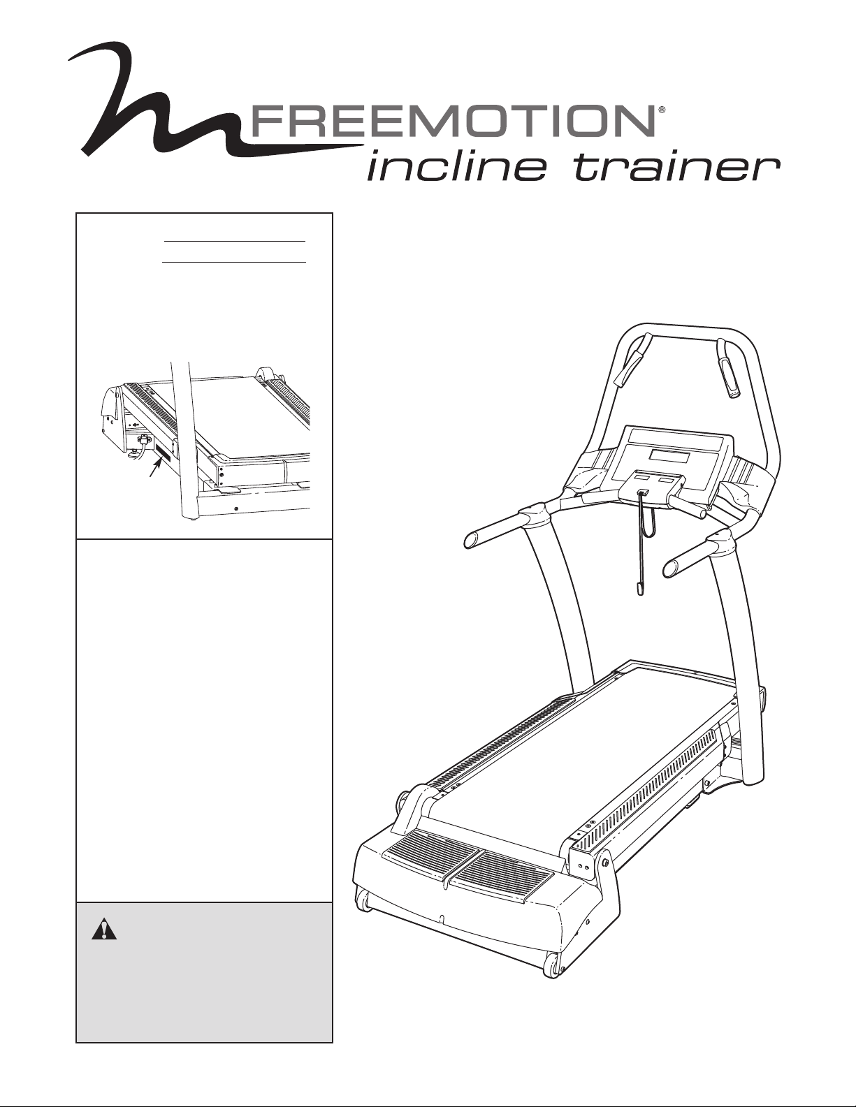
Model No.
Serial No.
The model number and serial number are found in the location shown
below. Write the model number and
serial number in the space above.
Serial
Number
Decal
QUESTIONS?
If you have questions, or if parts
are damaged or missing, please
see HOW TO CONTACT CUSTOMER CARE on the back cover
of this manual.
USERʼS MANUAL
CAUTION
Read all precautions and instructions in this manual before using
this equipment. Keep this manual
for future reference.
www.freemotionfitness.com
Page 2

TABLE OF CONTENTS
WARNING DECAL PLACEMENT . . . . . . . . . . . . . . . . . . . . . . . . . . . . . . . . . . . . . . . . . . . . . . . . . . . . . . . . . . . . . .3
IMPORTANT PRECAUTIONS . . . . . . . . . . . . . . . . . . . . . . . . . . . . . . . . . . . . . . . . . . . . . . . . . . . . . . . . . . . . . . . . .4
BEFORE YOU BEGIN . . . . . . . . . . . . . . . . . . . . . . . . . . . . . . . . . . . . . . . . . . . . . . . . . . . . . . . . . . . . . . . . . . . . . . .6
SSEMBLY . . . . . . . . . . . . . . . . . . . . . . . . . . . . . . . . . . . . . . . . . . . . . . . . . . . . . . . . . . . . . . . . . . . . . . . . . . . . . . .7
A
HOW TO CONNECT THE INCLINE TRAINER . . . . . . . . . . . . . . . . . . . . . . . . . . . . . . . . . . . . . . . . . . . . . . . . . . .11
HOW TO MOVE THE INCLINE TRAINER . . . . . . . . . . . . . . . . . . . . . . . . . . . . . . . . . . . . . . . . . . . . . . . . . . . . . . .12
HOW TO UPGRADE THE CONSOLE . . . . . . . . . . . . . . . . . . . . . . . . . . . . . . . . . . . . . . . . . . . . . . . . . . . . . . . . . .12
HOW TO USE THE BASIC CONSOLE . . . . . . . . . . . . . . . . . . . . . . . . . . . . . . . . . . . . . . . . . . . . . . . . . . . . . . . . .13
PREVENTIVE MAINTENANCE . . . . . . . . . . . . . . . . . . . . . . . . . . . . . . . . . . . . . . . . . . . . . . . . . . . . . . . . . . . . . . .23
SIX-MONTH PREVENTIVE MAINTENANCE RECORD . . . . . . . . . . . . . . . . . . . . . . . . . . . . . . . . . . . . . . . . . . . .26
TROUBLESHOOTING . . . . . . . . . . . . . . . . . . . . . . . . . . . . . . . . . . . . . . . . . . . . . . . . . . . . . . . . . . . . . . . . . . . . . .27
EXERCISE GUIDELINES . . . . . . . . . . . . . . . . . . . . . . . . . . . . . . . . . . . . . . . . . . . . . . . . . . . . . . . . . . . . . . . . . . .29
PART LIST . . . . . . . . . . . . . . . . . . . . . . . . . . . . . . . . . . . . . . . . . . . . . . . . . . . . . . . . . . . . . . . . . . . . . . . . . . . . . . .30
EXPLODED DRAWING . . . . . . . . . . . . . . . . . . . . . . . . . . . . . . . . . . . . . . . . . . . . . . . . . . . . . . . . . . . . . . . . . . . . .32
HOW TO CONTACT CUSTOMER CARE . . . . . . . . . . . . . . . . . . . . . . . . . . . . . . . . . . . . . . . . . . . . . . . .Back Cover
FREEMOTION is a registered trademark of ICON IP, Inc.
2
Page 3
HAZARDOUS
VOLTAGE
Disconnect power
before servicing.
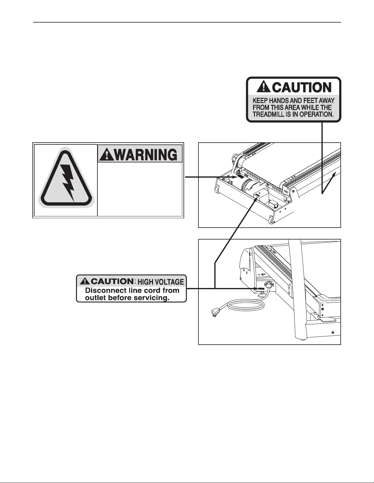
WARNING DECAL PLACEMENT
hese drawings show the locations of the warning decals. If a decal is missing or illegible, see the back cover
T
of this manual and request a free replacement decal. Apply the decal in the location shown. Note: The decals may not be shown at actual size.
Note: There
is one decal
on each side.
3
Page 4

IMPORTANT PRECAUTIONS
WARNING: To reduce the risk of serious injury, read all important precautions and in-
tructions in this manual and all warnings on your incline trainer before using your incline trainer.
s
FreeMotion Fitness assumes no responsibility for personal injury or property damage sustained by or
through the use of this product.
1. Before beginning any exercise program, consult your physician. This is especially important for persons over age 35 or persons with
pre-existing health problems.
2. It is the responsibility of the owner to ensure
that all users of the incline trainer are adequately informed of all warnings and precautions.
3. Use the incline trainer only as described in
this manual.
4. Place the incline trainer on a level surface,
with at least 8 ft. (2.4 m) of clearance behind it
and 2 ft. (0.6 m) on each side. Do not place
the incline trainer on a surface that blocks
any air openings. To protect the floor or carpet from damage, place a mat under the incline trainer.
5. Keep the incline trainer indoors, away from
moisture and dust. Do not place the incline
trainer in a garage or covered patio, or near
water.
6. Do not operate the incline trainer where
aerosol products are used or where oxygen is
being administered.
7. Keep children under age 12 and pets away
from the incline trainer at all times.
8. The incline trainer should be used only by
persons weighing 350 lbs. (159 kg) or less.
9. Never allow more than one person on the
incline trainer at a time.
10. Wear appropriate exercise clothes when
using the incline trainer. Do not wear loose
clothes that could become caught in the incline trainer. Athletic support clothes are recommended for both men and women. Always
wear athletic shoes. Never use the incline
trainer with bare feet, wearing only stockings,
or in sandals.
11. When connecting the power cord, follow the instructions on page 11. No other appliance
should be on the same circuit as the incline
trainer. Do not use an extension cord.
12. Keep the power cord away from heated surfaces.
13. Never move the walking belt while the power
is turned off. Do not operate the incline
trainer if the power cord or plug is damaged
or if the incline trainer is not working properly. (See TROUBLESHOOTING on page 27 if
the incline trainer is not working properly.)
14. Read, understand, and test the emergency
stop procedure before using the incline
trainer (see HOW TO TURN ON THE POWER
on page 14).
15. Never start the incline trainer while you are
standing on the walking belt. Always hold the
handrails while using the incline trainer.
16. The incline trainer is capable of high speeds.
Adjust the speed in small increments to avoid
sudden jumps in speed.
17. The pulse sensor is not a medical device.
Various factors, including the user's movement, may affect the accuracy of heart rate
readings. The pulse sensor is intended only
as an exercise aid in determining heart rate
trends in general.
18. Never leave the incline trainer unattended
while it is running. Always remove the key,
unplug the power cord, and switch the
reset/off circuit breaker to the off position
when the incline trainer is not in use. (See the
drawing on page 6 for the location of the circuit breaker.)
4
Page 5

19. Do not attempt to move the incline trainer
until it is properly assembled. (See ASSEM-
LY on page 7, and HOW TO MOVE THE IN-
B
CLINE TRAINER on page 12.) You must be
able to safely lift 45 lbs. (20 kg) to move the
incline trainer.
20. Do not change the incline of the incline
trainer by placing objects under it.
21. Never insert or drop any object into any
opening on the incline trainer.
22. Make sure to perform all maintenance proce-
dures outlined in this manual. Failure to do so
SAVE THESE INSTRUCTIONS
will void the warranty and may result in damage to the incline trainer.
23. Inspect and properly tighten all parts of the
ncline trainer regularly.
i
DANGER: Always unplug the power
24.
cord before cleaning the incline trainer and
before performing the maintenance and adjustment procedures described in this manual. Servicing other than the procedures in
this manual should be performed by an authorized service representative only.
5
Page 6
BEFORE YOU BEGIN
Congratulations for selecting the revolutionary
FREEMOTION®INCLINE TRAINER. The INCLINE
TRAINER offers an impressive array of features to
ake your workouts more effective and enjoyable.
m
For your benefit, read this manual carefully before
you use the incline trainer. If you have questions
after reading this manual, please see the back cover of
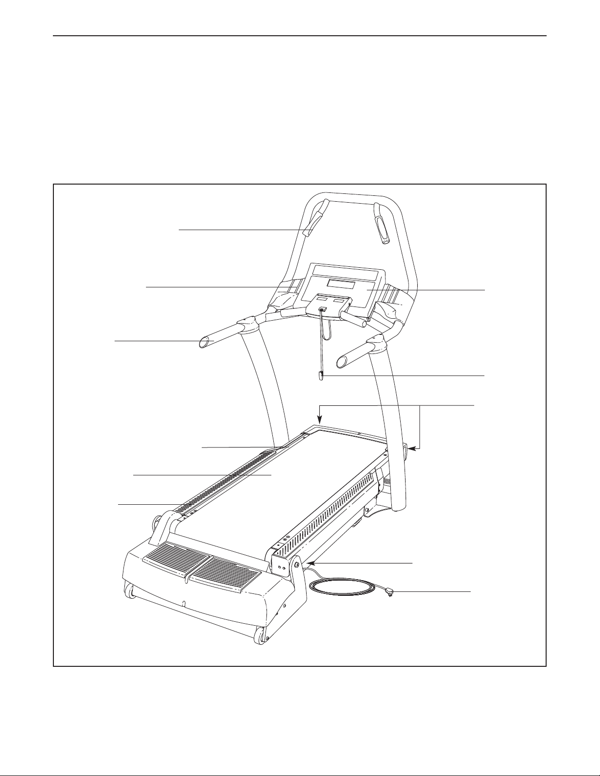
Handgrip Pulse Sensor
Accessory Tray
Handrail
this manual. To help us assist you, note the product
model number and serial number before contacting us.
The model number and serial number are found on the
erial number decal. The location of the serial number
s
decal is shown on the front cover of this manual.
Before reading further, please familiarize yourself with
the parts that are labeled in the drawing below.
Console
Cushioned Walking Platform
Walking Belt
Foot Rail
Key/Clip
Idler Roller
Adjustment Bolts
Reset/Off Circuit Breaker
Power Cord
6
Page 7
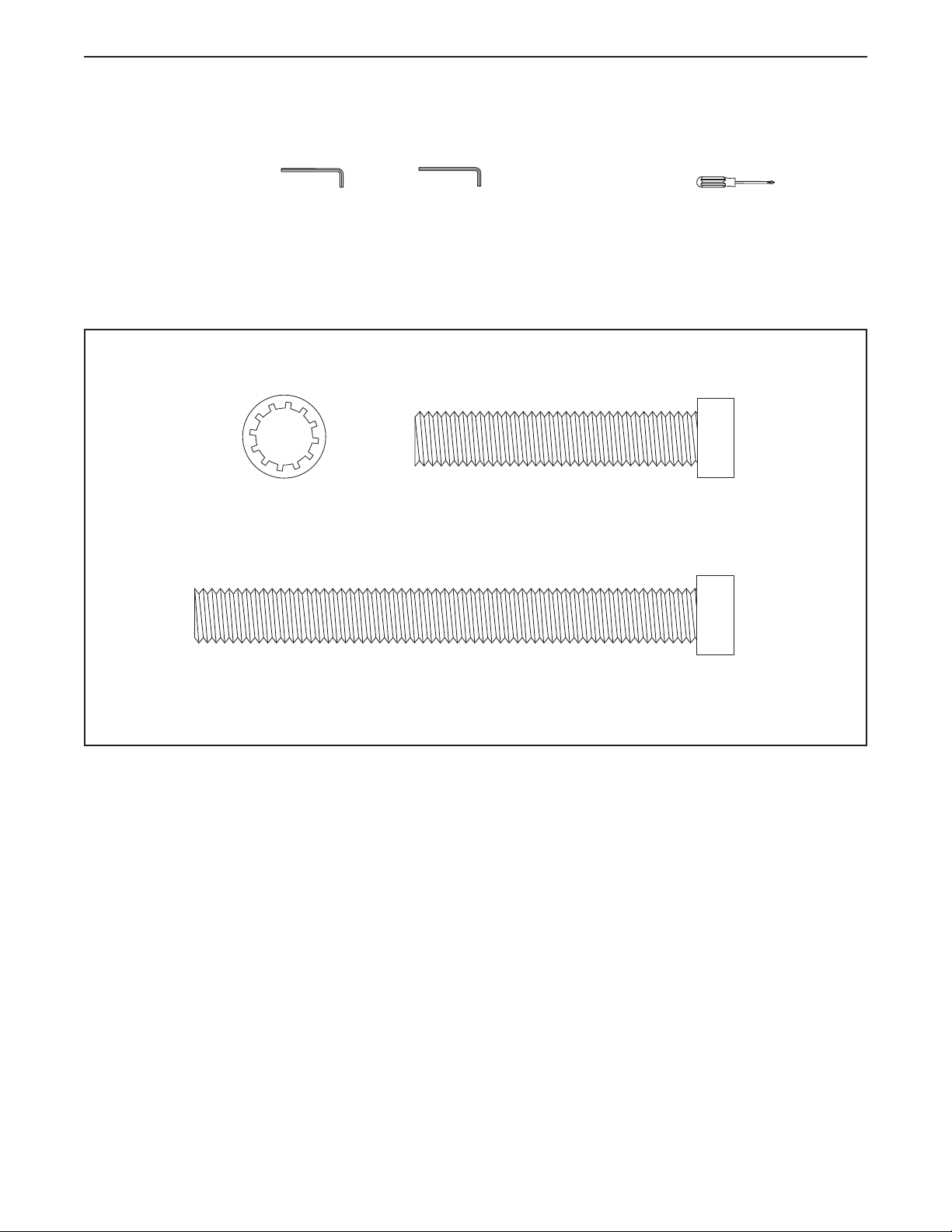
1/2" Star
Washer (124)–4
1/2" x 2 1/2" Bolt (95)–4
1/2" x 4 1/2" Bolt (96)–4
ASSEMBLY
Assembly requires two persons. Set the incline trainer in a cleared area and remove all packing materials. Do
not dispose of the packing materials until assembly is completed.
Assembly requires a 3/8" hex key , a 7/32" hex key , and a Phillips screwdriver .
Use the drawings below to identify the assembly hardware. The number in parentheses below each drawing is
the key number of the part, from the PART LIST near the end of this manual. The number after the parentheses
is the quantity needed for assembly. Note: If a part is not in the hardware kit, check to see if it is preattached
to one of the parts to be assembled. To avoid damaging plastic parts, do not use power tools for assembly. Extra hardware may be included.
7
Page 8
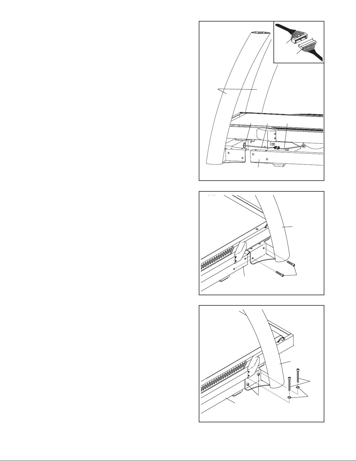
1. Place the Uprights (93) near the front of the Base Frame
(56) as shown.
onnect the 80" Wire Harness (127) and the 72" Wire
C
Harness (132) wires on the right side of the incline
rainer. See the inset drawing. The connectors should
t
slide together easily and snap into place. If they do
not, turn one connector and try again. IF THE CONNEC-
TORS ARE NOT INSERTED PROPERLY, THE CONSOLE MAY BE DAMAGED WHEN THE POWER IS
TURNED ON.
1
132
127
93
Insert the excess wire into the indicated hole in the
Uprights (93).
2. Slide the Uprights (93) onto the Base Frame (56), and
align the holes in the Uprights with the holes in the Base
Frame. Be careful to avoid pinching the wires.
Partially tighten two 1/2" x 2 1/2" Bolts (95) through the
bracket near the right Upright and into the Base Frame;
do not tighten the Bolts yet.
Repeat this step on the left side of the incline trainer;
there are no wires on the left side.
RIGHT
Hole
LEFT
2
132
56
127
93
3. Partially tighten two 1/2" x 4 1/2" Bolts (96) with two 1/2"
Star Washers (124) through the top of the bracket near
the right Upright (93) and into the Base Frame (56); do
not tighten the Bolts yet.
Repeat this step on the left side of the incline trainer.
Then, tighten the 1/2" x 4 1/2" Bolts (96) and the 1/2" x 2
1/2" Bolts (95) on both sides.
8
56
3
95
56
95
93
96
124
Page 9
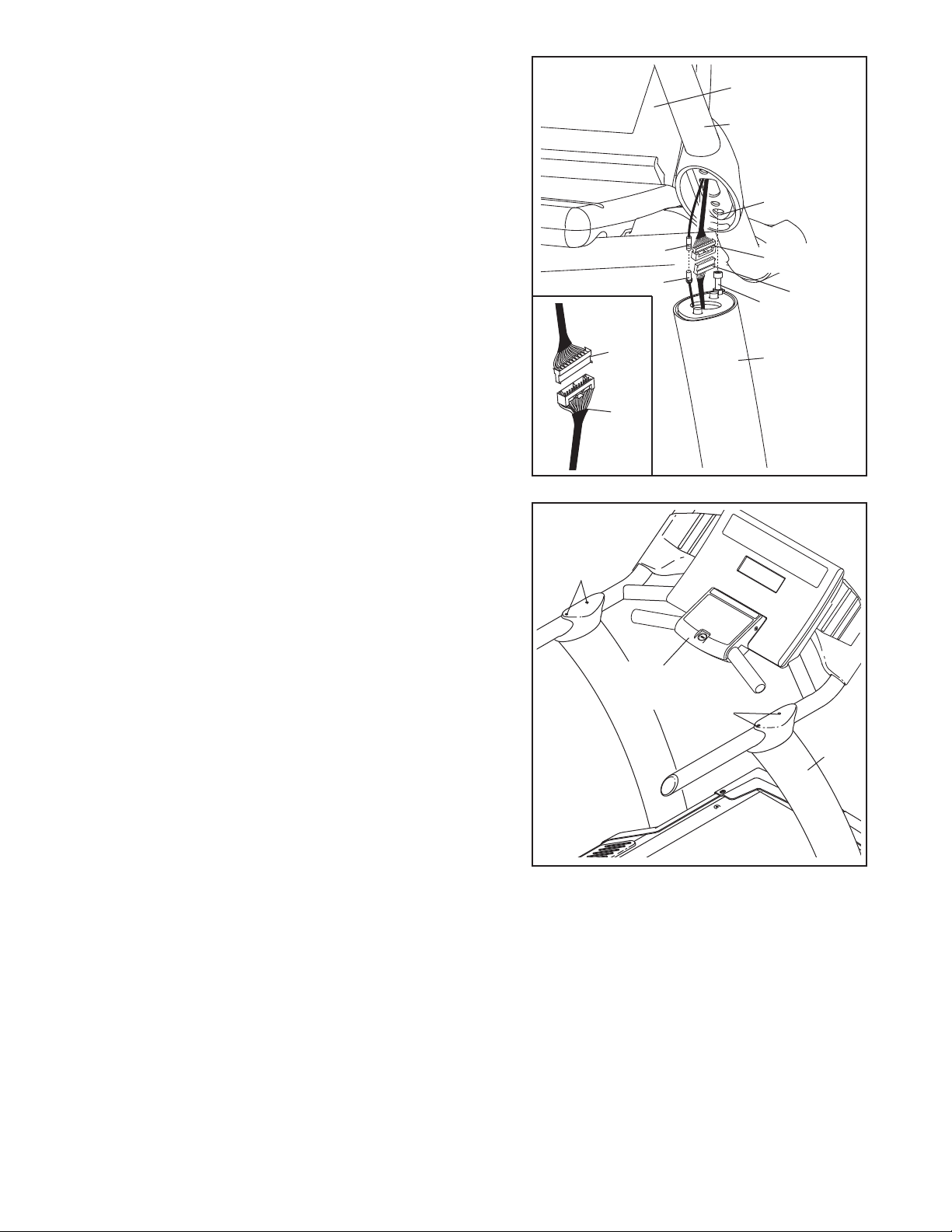
4. Locate the Bolt (B) on the top of each Upright (93). With
the help of a second person, set the console assembly
onto the top of the Uprights. Make sure that the Bolts
re inserted into the indicated holes in the bottom of
a
the console assembly (only one side is shown). Be
areful not to pinch any wires. Pull up on the Handrail
c
(103) and carefully tip the console assembly forward so
that you can see the indicated wires (132, 139). Make
sure the console assembly is held securely by the
Bolts.
Connect the 72" Wire Harness (132) to the 35" Wire
Harness (135). See the inset drawing. The connectors
should slide together easily and snap into place. If
they do not, turn one connector and try again. IF THE
CONNECTORS ARE NOT INSERTED PROPERLY,
THE CONSOLE MAY BE DAMAGED WHEN THE
POWER IS TURNED ON. If there is a 65" TV Cable
(125), connect the Cable to the 45" TV Cable (140).
Then, insert the wires down into the right Upright.
4
140
125
135
132
Console
Assembly
103
ole
H
135
B
93
132
5. With the help of a second person, pivot the console assembly to the position shown. Be careful to avoid
pinching your hands or the wires.
Align the 3/8" x 2 3/4" Bolts (102) with the holes in the
tops of the Uprights (93). Start all four Bolts, and then
firmly tighten them.
5
102
Console
Assembly
102
93
9
Page 10
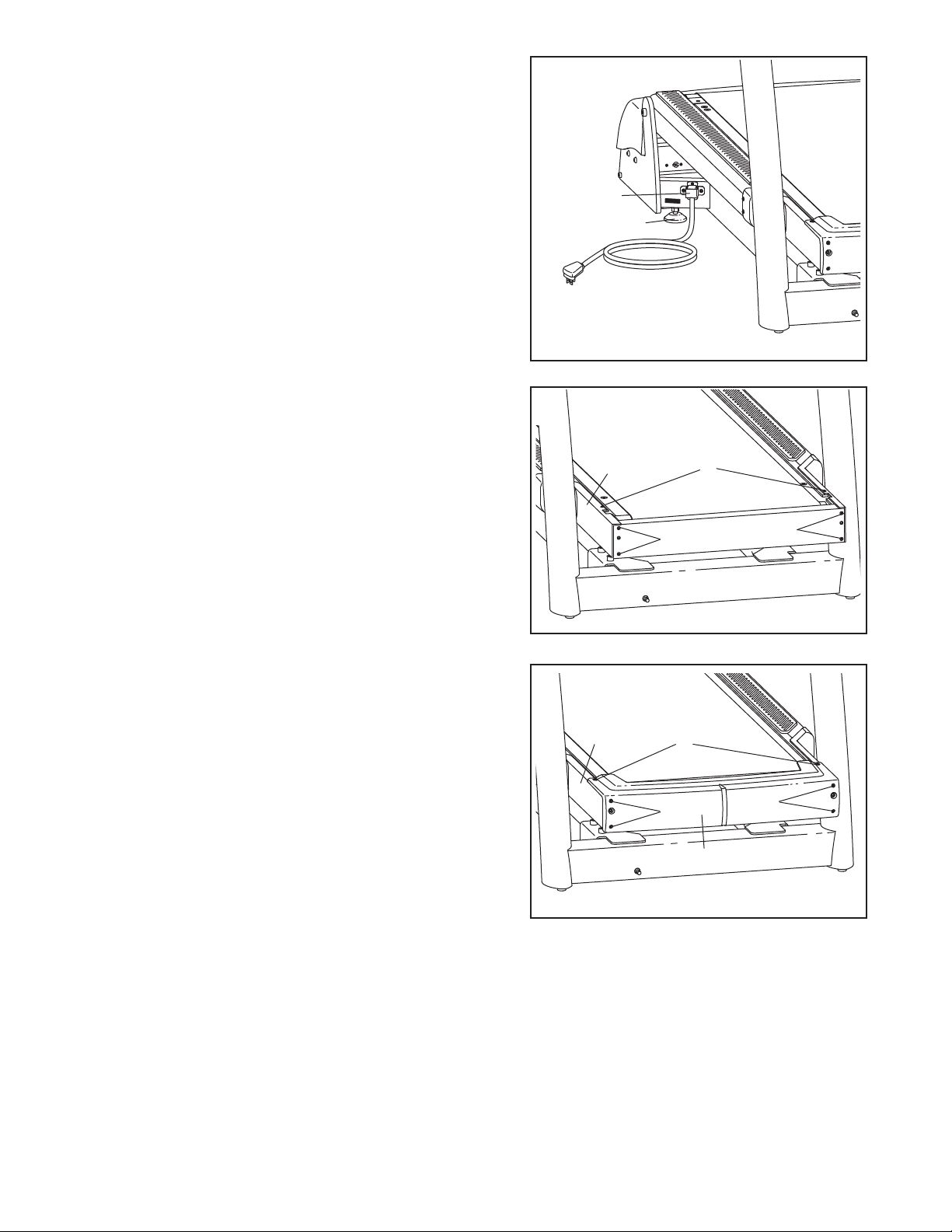
6. After the incline trainer is placed in the location where it
will be used (see HOW TO MOVE THE INCLINE
TRAINER on page 12), make sure that both Rear
Leveling Feet (38) and the Base Pads (not shown) rest
firmly on the floor. If the incline trainer rocks even
lightly, turn one Rear Leveling Foot clockwise or coun-
s
terclockwise until the rocking motion is eliminated.
Note: The Power Cord Bracket (64) must be attached at all times.
6
64
38
7. Remove the two #8 x 1/2" Washer Head Screws (2)
and the four #8 x 3/4" Screws (16) from the Frame
(22).
8. Attach the Front Cover (17) to the Frame (22) with the
two #8 x 1/2" Washer Head Screws (2) and the four #8
x 3/4" Screws (16) that you removed in step 7.
7
22
8
22
16
16
2
16
2
16
17
9. Make sure that all parts are properly tightened before you use the incline trainer. To protect the floor or
carpet, place a mat beneath the incline trainer.
10
Page 11
HOW TO CONNECT THE INCLINE TRAINER
HOW TO CONNECT THE POWER CORD IN THE UK
DANGER: Improper connection
his product must be earthed. If it should malfunc-
of the equipment-grounding conductor can
esult in an increased risk of electric shock.
r
Check with a qualified electrician or serviceman if you are in doubt as to whether the
product is properly grounded. Do not modify
the plug provided with the product—if it will
not fit the outlet, have a proper outlet
installed by a qualified electrician. Do not use
an adapter to connect the plug to an improper
receptacle.
HOW TO CONNECT THE POWER CORD IN THE
UNITED STATES
This product must be grounded. If it should malfunc-
tion or break down, grounding provides a path of least
resistance for electric current to reduce the risk of electric shock.
T
tion or break down, earthing provides a path of least
resistance for electric current to reduce the risk of electric shock.
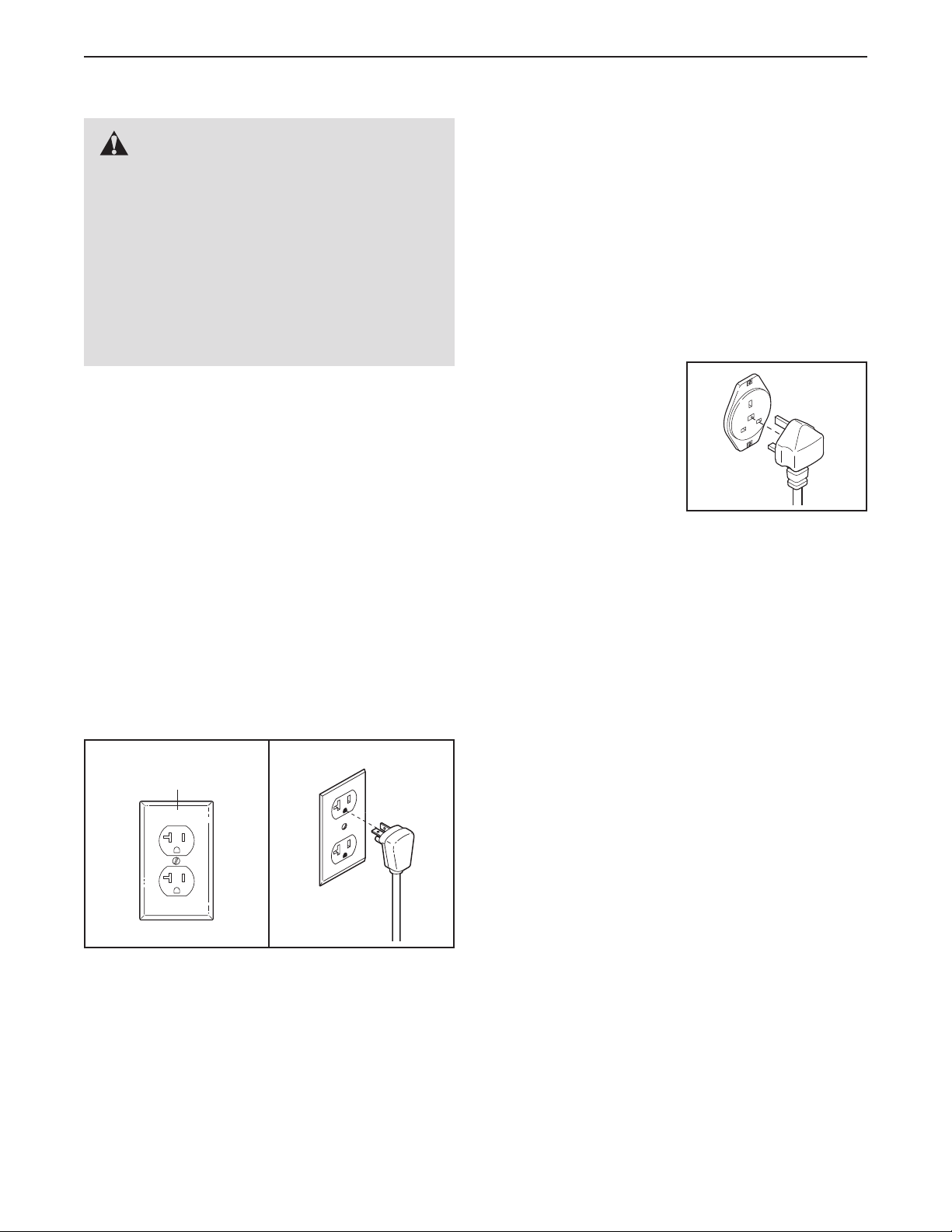
This product is for use on a dedicated, 10-amp,
240-volt circuit. No other appliance should be on
the same circuit. The product is equipped with a cord
having an equipment-earthing conductor and an earthing plug.
Plug the earthing plug
into a receptacle as
shown at the right. Do
not modify the plug or
the receptacle. Do not
use an adapter or an extension cord. The receptacle must be earthed.
This product is for use on a dedicated, 20-amp,
120-volt circuit. No other appliance should be on
the same circuit. This product is equipped with a cord
having an equipment-grounding conductor and a
grounding plug.
Plug the grounding plug into a standard NEMA 5-20
receptacle. Do not modify the plug or the receptacle.
Do not use an adapter, a surge protector, or an extension cord. The receptacle must be grounded.
NEMA 5-20
Receptacle
11
Page 12

HOW TO MOVE THE INCLINE TRAINER
Before moving the incline trainer, unplug the power
cord. Note: It may be necessary to disconnect a CATV
cable from the incline trainer, depending on how far the
incline trainer will be moved.
Due to the size and weight of the incline trainer, moving it requires two or three persons. Hold the metal
frame firmly in the location shown at the right. CAUTION: To decrease the possibility of damage to the
incline trainer or of injury, do not lift the frame by the
plastic front cover. Carefully roll the incline trainer on
the wheels to the desired location and then lower it back
to the level position. CAUTION: To reduce the risk of in-
jury, use extreme caution while moving the incline
trainer. Do not attempt to move the incline trainer
over uneven surfaces.
Front
Cover
Frame
Wheels
HOW TO UPGRADE THE CONSOLE
Your incline trainer has been preconfigured to operate with a basic console and with an optional personal television, which offers additional functionality. With the optional personal television, you can watch the television programs of your choice, or connect and use your own VCR or DVD player. To purchase the optional personal television, please see the back cover of this manual.
12
Page 13

HOW TO USE THE BASIC CONSOLE
FEATURES OF THE CONSOLE
The incline trainer console offers an impressive array
of features designed to make your workouts more effective and enjoyable. When you use the manual mode
of the console, you can change the speed and incline
of the incline trainer with the touch of a button. As you
exercise, the console will display continuous exercise
feedback. You can even measure your heart rate using
the handgrip pulse sensor.
In addition, the console features fourteen personal
trainer workouts. Each preset workout automatically
controls the speed and incline of the incline trainer as it
guides you through an effective workout.
The console also offers twelve interactive trainer workouts that allow you to customize your workout. The interactive trainer workouts include three heart rate
workouts that control the speed and incline of the incline trainer to keep your heart rate near the target
heart rate settings. In addition, three fitness test workouts measure your fitness level or your VO
The console also features the new iFit interactive workout system. The iFit system is compatible with incline
2 max.
trainer iFit interactive workout cards containing workouts designed to help you achieve specific fitness
goals. For example, lose unwanted pounds with the iFit
Weight Loss workout, or train for a long-distance run
with the iFit Marathon workout. iFit workouts automatically control the speed and incline of the incline trainer.
To purchase iFit cards, please see the front cover
of this manual or go to www.iFit.com. iFit cards are
also available at select stores.
Whether you select the manual mode or a workout,
you can watch the television programs of your choice
on the optional personal television. You can even listen
to your favorite workout music or audio books with the
consoleʼs sound system.
To turn on the power, see page 14. To use the manual mode, see page 14. To use a personal trainer
workout, see page 16. To use a walk/run workout or
a manual control workout, see page 17. To use a
fitness test workout, see page 18. To use a heart
rate workout, see page 19. To use a custom workout, see page 20. To use an iFit workout, see page
21. To use the maintenance mode, see page 22. To
use the sound system, see page 22.
13
Page 14

HOW TO TURN ON THE POWER
HOW TO USE THE MANUAL MODE
IMPORTANT: If the incline trainer has been ex-
osed to cold temperatures, allow it to warm to
p
room temperature before turning on the power. If
ou do not do this, the console displays or other
y
electrical components may become damaged.
Plug in the power cord
(see page 11). Next,
locate the reset/off circuit breaker on the incline trainer frame near
the power cord. Make
sure that the circuit
breaker is in the “reset”
position.
Next, stand on the foot
rails of the incline
trainer. Locate the clip
attached to the key
(see the drawing at the
right), and slide the clip
securely onto the
waistband of your
clothes. Then, insert the key into the console. After a
moment, the displays will light. IMPORTANT: In an
emergency situation, the key can be pulled from
the console, causing the walking belt to slow to a
stop. Test the clip by carefully taking a few steps
backward; if the key is not pulled from the console,
adjust the position of the clip.
Reset
Position
Key
Clip
1. Insert the key into the console.
See HOW TO TURN ON THE POWER at the left.
2. Select the manual mode.
Each time the key
is inserted, the
manual mode will
be selected. If you
have selected a
workout, press any
of the workout buttons repeatedly until zeros appear in the display.
3. Start the walking belt and adjust the speed.
To start the walking belt, press the Start/Stop button or the Speed increase button. As you exercise,
change the speed of the walking belt as desired by
pressing the Speed increase and decrease buttons
next to the Start/Stop button. Each time you press
a button, the speed setting will change; if you hold
down a button, the speed setting will change in
larger increments.
To stop or restart the walking belt, press the
Start/Stop button.
4. Change the incline of the incline trainer as desired.
IMPORTANT: If there is a sheet of clear plastic on
the face of the console, remove the plastic. To prevent damage to the walking platform, wear clean
athletic shoes while using the incline trainer. The
first time the incline trainer is used, observe the
alignment of the walking belt, and center the walking belt if necessary (see page 28).
Note: The console will display speed and distance in
either miles or kilometers. For simplicity, all instructions
in this section refer to miles.
To change the incline of the incline trainer, press
the Incline increase or decrease button, or one of
the numbered Quick Touch Incline buttons. Each
time you press one of the buttons, the incline will
gradually change until it reaches the selected incline setting. Note: You can lower the incline to a
setting below zero percent.
14
Page 15

5. Select a display mode and monitor your
progress with the display.
hen the manual
W
mode is selected,
he console offers
t
seven display
modes. The display
mode that you select will determine which workout information is
shown. Press the Display button repeatedly to select the desired display mode.
As you walk or run on the incline trainer, the upper
display can show the following workout information:
• The elapsed time.
• The distance that you have walked or run.
• The speed of the walking belt.
• The incline level of the incline trainer.
• The approximate number of calories you have
burned.
• The approximate number of calories burned per
hour.
• Your exercise intensity in METs. One MET is the
amount of energy you use while resting.
• Your walking or running pace, in minutes per mile
or minutes per kilometer.
As you switch between workouts and the manual
mode, the console will keep track of the total distance that you have walked or run and the approxi-
ate number of calories you have burned. You can
m
keep your totals even when you switch to a new
orkout. To reset the console, press the Clear but-
w
ton.
6. Measure your heart rate if desired.
Before using
the handgrip
pulse sensor,
remove the
sheets of clear
plastic from
the metal contacts. In addition, make
sure that your
hands are clean.
To measure your heart rate, stand on the foot
rails and hold the contacts for approximately ten
seconds—avoid moving your hands. When your
pulse is detected, your heart rate will be shown.
For the most accurate heart rate reading, continue to hold the contacts for about 15 seconds.
7. When you are finished exercising, remove the
key from the console.
Step onto the foot rails, press the Stop button, remove the key from the console, and put it in a secure
place.
Contacts
• An animation of a road.
Regardless of which display mode you select, the
speed or incline setting will appear in the display for
a few seconds each time you change the setting.
When you are finished using the incline trainer,
switch the reset/off circuit breaker to the “off” position and unplug the power cord. IMPORTANT: If
you do not do this, the incline trainerʼs electrical components may wear prematurely.
15
Page 16

HOW TO USE A PERSONAL TRAINER WORKOUT
1. Insert the key into the console.
See HOW TO TURN ON THE POWER on page
4.
1
2. Select one of the personal trainer workouts.
To select a personal trainer workout, press the
Random Workouts
button, the Interval
Workouts button,
or the Terrain Workouts button repeatedly until the
name of the desired workout appears in the display. Random workouts use preset random speed
and incline settings. Interval workouts use incline
settings to provide a personalized workout. Terrain
workouts use speed and incline settings to simulate an actual walking experience.
When a workout is selected, the display will show
the name, the maximum incline setting, the maximum speed setting and the duration of the workout. The display will also show a profile of the incline settings of the workout.
Press the Enter button to select the desired workout. Select your age and your weight using the
Increase and Decrease buttons next to the Enter
button. Press the Enter button after each selec-
tion. Note: To use the Interval workouts, you must
also enter your minimum and maximum incline settings using the Quick Touch Incline buttons or the
Incline increase and decrease buttons.
3. Press the Start/Stop button to start the workout.
A moment after you press the Start/Stop button,
the incline trainer will automatically adjust to the
first speed and incline settings of the workout. Hold
the handrails and begin walking.
Each workout is divided into segments. One speed
setting and one incline setting are programmed for
each segment. Note: The same speed and/or incline
setting may be programmed for consecutive segments.
During the workout, the profile will show your
progress. The flashing segment of the profile represents the current segment of the workout. The
height of the flashing segment indicates the incline
setting for the current segment. At
the end of each
egment, the next
s
segment of the pro-
ile will begin to
f
flash and the speed and incline settings will appear
at the top of the display for a few moments to alert
you.
The workout will continue in this way until the last
segment of the profile flashes in the display and
the last segment ends. The walking belt will then
slow to a stop.
If the speed or incline setting is too high or too low
at any time during the workout, you can manually
override the setting by pressing the Speed or
Incline buttons; however, when the next segment
of the workout begins, the incline trainer will automatically adjust to the speed and incline settings for the next segment. Note: If you use an
Interval workout, the speed will not adjust automatically.
To stop or restart the workout at any time, press
the Start/Stop button.
4. Select a display mode and monitor your
progress with the display.
The console offers three display modes. The display mode that you select will determine which
workout information is shown. Press the Display
button repeatedly to select the desired display
mode.
The display can show the speed of the walking belt,
the incline of the incline trainer, a profile of the
workout, the time remaining in the workout, the distance you have walked or run, the approximate
number of calories you have burned, your exercise
intensity in METs, the approximate number of calories burned per hour, your pace, and your power
output in watts.
5. Measure your heart rate if desired.
See step 6 on page 15.
6. When you are finished exercising, remove the
key from the console.
See step 7 on page 15.
Current Segment
16
Page 17

HOW TO USE A WALK/RUN WORKOUT OR A
MANUAL CONTROL WORKOUT
. Insert the key into the console.
1
ee HOW TO TURN ON THE POWER on page
S
14.
2. Select one of the workouts.
To select a walk/run workout, press the Walk/Run
Workouts button repeatedly until the 5K Walk, the
10K Run, or the Cross Country workout appears in
the display.
To select a manual
control workout,
press the Manual
Control button repeatedly until the
Manual Time, the
Manual Vertical Distance, or the Manual Calories
workout appears in the display.
3. Press the Start/Stop button to start the workout.
A moment after you press the Start/Stop button,
he incline trainer will begin moving. Hold the
t
handrails and begin walking.
During the workout, the profile will show the incline
of the walking belt. As you exercise, change the
speed and incline of the walking belt as desired by
pressing the Speed and Incline increase and decrease buttons.
The workout will continue until you reach your distance, time, vertical distance, or calorie goal. The
walking belt will then slow to a stop.
To stop or restart the workout at any time, press
the Start/Stop button.
4. Select a display mode and monitor your
progress with the display.
See step 4 on page 16.
The display will show the name, and the distance,
time, vertical distance, or calorie goal of the workout.
Press the Enter button to select the desired workout. Select your age and then your weight using
the Increase and Decrease buttons next to the
Enter button. Press the Enter button after each
selection. Note: To use the cross country workouts, you must also enter your distance goal. To
use a manual control workout, enter your time, vertical distance, or calorie goal.
5. Measure your heart rate if desired.
See step 6 on page 15.
6. When you are finished exercising, remove the
key from the console.
See step 7 on page 15.
17
Page 18

HOW TO USE A FITNESS TEST WORKOUT
4. Press the Start/Stop button to start the workout.
The fitness test workouts measure your relative fitness
evel. For the most accurate results, use a fitness test
l
workout when you are not feeling tired, when you have
ot eaten for at least two hours, and when you have not
n
exercised for at least 24 hours.
The incline trainer features three fitness workouts. The
Ebbeling Fitness Test measures VO
2 max, or aerobic
capacity, and lasts 9 minutes. The Gerkin Fitness Test
also measures VO2 max. The Gerkin Fitness Test begins with a three-minute warm-up period and ends after
either 14 minutes or when you reach a certain heart
rate. The FreeMotion Fitness Test measures your fitness level on a scale of 1 to 10. The FreeMotion
Fitness Test ends after either 28 minutes or when you
reach a certain heart rate.
1. Put on a Polar®-compatible chest pulse sensor
(not included).
To use a fitness test workout, you must wear a
Polar-compatible chest pulse sensor or use the
handgrip pulse sensor. Note: For best results, you
should wear a chest pulse sensor.
2. Insert the key into the console.
A moment after you press the Start/Stop button,
he incline trainer will automatically adjust to the
t
first speed and incline settings of the fitness test.
egin walking on the incline trainer. Note: For the
B
most accurate results, do not hold the handrails
during a fitness test workout.
During the workout, the speed and incline of the incline trainer will periodically change. The speed
setting or the incline setting will appear in the display to alert you before each change.
IMPORTANT: The Speed and Incline buttons
will not function during a fitness test workout.
Note: If you press the Start/Stop button during the
fitness test, the fitness test will end.
When the workout ends, the walking belt will slow
to a stop and your fitness level or VO
2 max will ap-
pear in the display.
If your pulse is not detected during the workout, the
words CHECK HEART RATE MONITOR will appear in the display and the speed of the incline
trainer may automatically decrease. If your pulse is
still not detected, the fitness test will be aborted.
See HOW TO TURN ON THE POWER on page 14.
3. Select a fitness test workout.
To select a fitness test workout, press the Fitness
Tests button repeatedly until the name of the desired fitness test appears in the display.
Press the Enter button to select the desired workout. Select your age and then your weight using
the Increase and Decrease buttons next to the
Enter button. Press the Enter button after each
selection. Note: To use the Ebbeling Fitness Test,
you must also enter your gender.
5. Select a display mode and monitor your
progress with the display.
See step 4 on page 16. Note: The fitness tests will
display your fitness level instead of your exercise
intensity in METs.
6. When you are finished exercising, remove the
key from the console.
See step 7 on page 15.
18
Page 19

HOW TO USE A HEART RATE WORKOUT
CAUTION: If you have heart prob-
lems, or if you are over 60 years of age and
ave been inactive, do not use the pulse work-
h
outs. If you are taking medication regularly,
consult your physician to find out whether the
medication will affect your exercise heart rate.
trainer will automatically adjust to the first speed
and incline settings of the workout. Hold the
handrails and begin walking.
The heart rate workouts are divided into several
ne-minute segments. One target heart rate setting
o
is programmed for each segment. The same target
heart rate setting may be programmed for consecutive segments. For a shorter workout, simply stop
the workout before it ends.
1. Put on a Polar®-compatible chest pulse sensor
(not included).
To use a heart rate workout, you must wear a
Polar-compatible chest pulse sensor or use the
handgrip pulse sensor. Note: For best results, you
should wear a chest pulse sensor.
2. Insert the key into the console.
See HOW TO TURN ON THE POWER on page
14.
3. Select one of the heart rate workouts.
To select a heart rate workout, press the Heart
Rate Control button repeatedly until the desired
workout appears in the display. Press the Enter
button to select the desired workout.
Select your age and then your weight using the
Increase and Decrease buttons next to the Enter
button. Press the Enter button after each selec-
tion. Note: To use the constant heart rate and variable heart rate workouts, you must also enter your
target maximum heart rate. If the target maximum
heart rate setting is changed, the intensity level of
the entire workout will change. Note: To calculate
your target maximum heart rate see EXERCISE
INTENSITY on page 29.
During all heart rate workouts, the console will regularly compare your heart rate to the target heart
rate setting. If your heart rate is too far below or
above the target heart rate setting for the current
segment, the speed of the walking belt will automatically increase or decrease to bring your heart
rate closer to the target heart rate setting.
If the speed or incline setting is too high or too low
at any time during the workout, you can adjust the
setting with the Speed or Incline buttons. However,
each time the console compares your heart rate to
the target heart rate setting, the speed of the incline trainer may automatically change to bring
your heart rate closer to the target heart rate setting.
To stop or restart the workout at any time, press
the Start/Stop button.
5. Select a display mode and monitor your
progress with the display.
See step 4 on page 16.
6. When you are finished exercising, remove the
key from the console.
See step 7 on page 15.
4. Press the Start/Stop button to start the workout.
A moment after the Start/Stop button is pressed,
the walking belt will begin to move and the incline
19
Page 20

HOW TO USE A CUSTOM WORKOUT
1. Insert the key into the console.
See HOW TO TURN ON THE POWER on page
4.
1
2. Select one of the custom workouts.
To select a custom workout, press the Custom
Workouts button repeatedly until the desired workout
appears in the display.
sents the current segment of the workout. The
height of the flashing segment indicates the incline
setting for the current segment. At the end of each
egment, a series of tones will sound, the next seg-
s
ment of the profile will begin to flash, and the speed
r incline setting for the next segment will appear in
o
the display to alert you.
The workout will continue in this way until the last
segment of the profile flashes in the display and
the last segment ends. The walking belt will then
slow to a stop.
The display will show the name, the maximum incline setting, the maximum speed setting, and the
duration of the workout. Note: To create a custom
workout, see step 3 on page 22.
Press the Enter button to select the desired workout. Select your age and then your weight using
the Increase and Decrease buttons next to the
Enter button.
3. Press the Start/Stop button to start the workout.
A moment after you press the Start/Stop button,
the incline trainer will automatically adjust to the
first speed and incline settings that you programmed previously. Hold the handrails and begin
walking.
Each custom workout is divided into one-minute
segments. One speed setting and one incline setting are programmed for each segment.
During the workout,
the profile will show
your progress. The
flashing segment
of the profile repre-
Current Segment
If the speed or incline setting is too high or too low
at any time during the workout, you can manually
override the setting by pressing the Speed or
Incline buttons; however, when the next segment
of the workout begins, the incline trainer will automatically adjust to the speed and incline settings for the next segment.
To stop or restart the workout at any time, press
the Start/Stop button. The speed of the walking belt
will gradually increase to the speed setting of the
current segment.
4. Select a display mode and monitor your
progress with the display.
See step 4 on page 16.
5. Measure your heart rate if desired.
See step 6 on page 15.
6. When you are finished exercising, remove the
key from the console.
See step 7 on page 15.
20
Page 21

HOW TO USE AN IFIT WORKOUT
3. Press the Start/Stop button to start the workout.
1. Insert the key into the console.
See HOW TO TURN ON THE POWER on page
4.
1
2. Insert an iFit card and select a workout.
To use an iFit workout, insert an iFit card into the
iFit slot in the back of the console; make sure that
the iFit card is oriented so the missing corner is
facing downward and is inserted into the iFit slot.
Plug headphones (not included) into the headphone jack near the Start/Stop button.
iFit Slot
iFit Card
A moment after you press the Start/Stop button,
he incline trainer will automatically adjust to the
t
first speed and incline settings of the workout. Hold
he handrails and begin walking.
t
At the end of each one-minute segment, the speed
and incline settings for the next segment will appear
in the display and a series of tones will sound to
alert you. If a different speed and/or incline setting
is programmed for the next segment, three tones
will sound.
If the speed or incline setting for the current segment is too high or too low, you can manually override the setting by pressing the Speed or Incline
buttons; however, when the next segment be-
gins, the incline trainer will automatically adjust to the speed and incline settings for the
next segment.
To stop the workout at any time, press the
Start/Stop button. To restart the workout, press the
Start/Stop button or the Speed increase button.
The walking belt will begin to move. When the next
segment of the workout begins, the incline trainer
will automatically adjust to the speed and incline
settings for the next segment.
Next, select an iFit workout by pressing the
Increase and Decrease buttons next to the Enter
button. When an iFit workout is selected, the display will show the name of the workout, the maximum incline setting and the maximum speed setting of the workout, and the workout time.
Each iFit workout is divided into one-minute segments. One speed setting and one incline setting
are programmed for each segment. Note: The
same speed and/or incline setting may be programmed for consecutive segments.
4. Select a display mode and monitor your
progress with the display.
See step 4 on page 16.
5. Measure your heart rate if desired.
See step 6 on page 15.
6. When you are finished exercising, remove the
key from the console.
See step 7 on page 15.
CAUTION: Always remove iFit cards from the
iFit slot when you are not using them.
21
Page 22

HOW TO USE THE MAINTENANCE MODE
3. Create a custom workout.
The console has a maintenance mode that keeps track
f the total number of hours that the incline trainer has
o
been operated and the total distance that the walking
elt has moved. The maintenance mode also allows
b
you to adjust the maximum workout time, the pause
timeout, and the sleep timeout. You can also select the
desired language and disable or enable the safety key.
1. Select the maintenance mode.
To select the maintenance mode, hold down the
Clear button and the Enter button for three seconds.
Press the Display button to move between
screens. Press the Back button to return to a previous screen. To change the settings, press the
Increase and Decrease buttons next to the Enter
button.
2. Set user preferences.
When you select the maintenance mode, the display will show the total number of hours and the
total number of miles (or kilometers) that the walking belt has moved. Press the Display button to
move to the next screen.
If desired, create a custom workout. Press the
isplay button until the desired custom workout is
D
shown. Then press the Enter button. Program a
peed setting and an incline setting for the first
s
one-minute segment by pressing the Speed and
Incline buttons. Press the Enter button to move to
the next segment and continue programming segments for 30 segments. Press the Enter button
after you have programmed the last segment.
Then press the Display button until you exit the information mode.
To exit the maintenance mode at any time, remove the
key from the console.
You can also disable or enable the safety key. When
the safety key is enabled, the key must be inserted into
the console for the incline trainer to turn on. To disable
or enable the safety key, remove the key from the console and hold down the Clear button and the Enter button for several seconds. Push the Increase or
Decrease button. To enable the safety key, insert the
key into the console. For best results, operate the incline trainer with the safety key enabled.
HOW TO USE THE SOUND SYSTEM
Next, press the Display button to move the cursor
to the pause timeout. Set the pause timeout, if desired. The pause timeout begins when the walking
belt stops. When the pause timeout ends, the display will return to the main screen and your distance and calories count will be reset.
Press the Display button to move the cursor to the
sleep timeout. Set the sleep timeout, if desired.
The sleep timeout begins when the display returns
to the main screen. When the sleep timeout ends,
the incline will lower to the lowest setting and the
screen saver will appear.
Next, press the Display button to move to the next
screen. Set the default input, if desired. To use the
optional TV, select the TV mode. To use a VCR or
DVD player with the optional TV, select the RCA
mode. To use a personal media player, select the
MP3 mode.
Press the Display button to move to the default volume. Set the default volume, if desired.
To play music or audio books through the consoleʼs
sound system, you must connect your MP3 player, CD
player, or other personal audio player to the console
and plug headphones (not included) into the console.
To use the sound system, you will need an audio wire
(not included). Plug the audio wire into the MP3 jack
near the Start/Stop button. Then, plug the other end
into a jack on your MP3 player, CD player, or other
personal audio player. Make sure that the audio wire
is fully plugged in. To purchase an audio wire,
please see the back cover of this manual.
Next, plug headphones into the headphone jack near
the Start/Stop button. Press the Play button on your
MP3 player, CD player, or other personal audio player.
Then, adjust the volume on your personal audio
player.
If you are using a personal CD player and the CD
skips, set the CD player on the floor or another flat surface instead of on the console.
22
Page 23

PREVENTIVE MAINTENANCE
Regular maintenance is necessary for optimal performance and long life of the incline trainer. Please read and
ollow all instructions below. If the incline trainer is not maintained as described, components may wear ex-
f
cessively, the incline trainer may be damaged, and the warranty will be voided. If you have questions
about maintenance, please see the back cover of this manual. CAUTION: Make sure to remove the key and
unplug the power cord before performing any maintenance procedures.
WEEKLY MAINTENANCE
1. Unplug the power cord. Inspect and properly tighten all external parts of the incline trainer.
2. Apply a mild multi-purpose cleaner to a 100% cotton cloth and remove any dust and grime from the handrails,
uprights, foot rails, frame, and motor hood. In addition, wipe the walking platform along the sides of the walking belt. Do not use cleaners under the walking belt. Apply a small amount of mild multi-purpose cleaner to
a 100% cotton cloth and wipe the console and the screens. Do not spray cleaner directly onto the incline
trainer or use ammonia or acid-based cleaners.
3. Make sure that the walking belt is centered and properly tightened. If it is centered and runs smoothly, do not
make any adjustments. If the walking belt needs to be adjusted, see pages 27 and 28.
MONTHLY MAINTENANCE
1. Unplug the power cord. Remove the 3/8" x 1 1/4" Bolts (37)
attaching the Motor Hood (91), and lift off the Motor Hood.
2. Using a hand-held vacuum, clean the area under the Motor
Hood (not shown). Be careful to avoid touching any com-
ponents. Check the Drive Motor Belt (82) for wear and cracks.
If the Drive Motor Belt needs to be replaced, please see the
back cover of this manual.
3. Plug in the power cord and insert the key into the console. Press the START button. Be careful to avoid in-
jury; keep your hands away from moving parts and make sure that your clothes cannot become
caught in moving parts. While the walking belt is moving, check the incline trainer for unusual noises or
odors. If any of these problems exists, please see the back cover of this manual. Remove the key and unplug the power cord. Reattach the Motor Hood (91) with the 3/8" x 1 1/4" Bolts (37).
1
37
91
37
2
82
4. Hold a clean, dry towel between the walking platform and the walking belt. Pull the towel from side to side
along the length of the walking platform. Rotate the walking belt and repeat this step until the entire walking
belt has been cleaned.
23
Page 24

TURNING THE WALKING PLATFORM
50"
Both sides of the walking platform are designed to be used as walking surfaces. Inspect the walking platform peri-
dically for wear. If there is any wood showing through the phenolic coating, or if the surface is damaged, the
o
walking platform should be turned over. The walking platform will need to be turned over and the walking belt re-
laced (see page 25) after every 16,000 to 24,000 kilometers (10,000 to 15,000 miles). Follow the instructions
p
below to turn over the walking platform.
1. Remove the key and unplug the
power cord. Remove the #8 x
3/4" Screws (16), #8 x 1/2"
Washer Head Screws (2) and the
Front Cover (17). Remove the 3/8"
x 5" Bolt (19) and the 3/8" Star
Washer (14) from each side of the
Idler Roller (13).
2. Remove the four 3/8" x 1 3/4"
Bolts (10) and the two 3/8" x 1 1/2"
Bolts (20). (Note: Be very careful
to avoid chipping or damaging
the phenolic coating on the
Walking Platform [23].) Lift the
Idler Roller (13) and slide it out of
the Walking Belt (18). Lift the
Walking Platform and the Walking
Belt to the position shown by the
dotted lines. Slide the Walking
Platform out of the Walking Belt,
turn it, and then slide it back into
the Walking Belt.
3. Lay down the Walking Platform (23) and the Walking Belt (18). Slide the Idler Roller (13) back into the Walking
Belt.
1–4
18
10
23
10
18
2
23
20
13
20
16
14
17
2
16
19
16
4. Reattach the Bolts (10, 20). Thread the 3/8" x 5" Bolt (19) with the 3/8" Star Washer (14) into the Idler Roller
(13). Reattach the Front Cover (17) with the #8 x 3/4" Screws (16) and the #8 x 1/2" Washer Head Screws (2).
5. Next, the Walking Belt (18) will need to be adjusted to the
proper tension. Using chalk, make two marks on the Walking
Belt exactly 50 in. (1.25 m) apart, as shown in the drawing.
Tighten both 3/8" x 5" Bolts (19, see the drawing above) until
the two chalk marks move apart an additional 3/16 to 1/4 in.
(5 to 6 mm). As you tighten the 3/8" x 5" Bolts, the Idler Roller
(13) will move. If the Idler Roller stops moving, do not fur-
ther tighten the Bolts; please see the back cover of this
manual. Make sure to keep the Walking Belt centered.
5
18
13
24
Page 25

REPLACING THE WALKING BELT
When the walking belt becomes worn, it should be replaced. The walking belt will need to be replaced after every
0,000 to 15,000 miles (16,000 to 24,000 kilometers). See the Service Manual for replacement instructions.
1
Please see the back cover of this manual to order a new walking belt.
REPLACING THE WALKING PLATFORM
When both sides of the walking platform become worn, the walking platform should be replaced. The walking
platform will need to be replaced after every 20,000 to 30,000 miles (32,000 to 48,000 kilometers). Please see the
back cover of this manual to order a new walking platform. Follow the instructions on page 24 to replace the walking platform.
25
Page 26

SIX-MONTH PREVENTIVE MAINTENANCE RECORD
Photocopy this form and use it to record the preventive maintenance performed on the incline trainer. Each copy of
the form can be used for six months (26 weeks). When maintenance is performed, write the date in the appropriate
paces. Make sure to perform each maintenance procedure as described on pages 23 to 25. If the proce-
s
dures are not performed as described, components may wear excessively, the incline trainer may be damaged, and the warranty will be voided.
Week1
Week2
Week3
Week4
Week5
Week6
Week7
Week8
Week9
Week10
Week11
Week12
Weekly Maintenance
Inspect and
tighten all external parts of
the incline
trainer.
/ /
/ /
/ / / /
/ / / /
/ / / /
/ / / /
/ / / /
/ / / /
/ / / /
/ / / /
/ / / /
/ / / /
Clean the
incline
trainer.
/ /
/ /
Check the
walking belt for
proper tension
and alignment.
/ /
/ /
/ /
/ /
/ /
/ /
/ /
/ /
/ /
/ /
/ /
/ /
Monthly Maintenance
Remove the
motor hood and
vacuum the
motor compartment.
Check the
motor belt for
cracks and
other wear.
/ / / / / /
/ / / / / /
Check the
motor for arcing; check for
noises or
odors.
Week13
Week14
Week15
Week16
Week17
Week18
Week19
Week20
Week21
Week22
Week23
Week24
Week25
Week26
Walking Platform Turned/Replaced Walking Belt Replaced
/ / / /
/ / / /
/ / / /
/ / / /
/ / / /
/ / / /
/ / / /
/ / / /
/ / / /
/ / / /
/ / / /
/ / / /
/ / / /
/ / / /
/ /
/ /
/ /
/ /
/ /
/ /
/ /
/ /
/ /
/ /
/ /
/ /
/ /
/ /
/ /
/ / / / / /
/ / / /
/ / / / / /
/ / / / / /
/ / / /
/ /
26
Page 27

TROUBLESHOOTING
ost incline trainer problems can be solved by following the steps below. Find the symptom that applies,
M
and follow the steps listed. If further assistance is needed, please see the back cover of this manual.
1. SYMPTOM: THE POWER DOES NOT TURN ON
a. Make sure that the power cord is plugged into a properly grounded outlet. (See page 11.)
b. Make sure that the key is inserted into the console.
c. Check the reset/off circuit breaker located on the incline trainer near the
power cord. Make sure that the reset/off circuit breaker is switched to the
“reset” position.
2. SYMPTOM: THE POWER TURNS OFF DURING USE
a. Check the reset/off circuit breaker located on the incline trainer near the power cord. (See drawing c above.)
Make sure that the reset/off circuit breaker is switched to the “reset” position.
b. Make sure that the power cord is plugged in.
c. Remove the key from the console. Reinsert the key into the console.
d. Check the walking belt and the walking platform for excessive wear. Replace the walking belt or the walking
platform if necessary.
e. If the power still turns off during use, please see the back cover of this manual.
3. SYMPTOM: THE WALKING BELT SLOWS WHEN WALKED ON
a. If the walking belt is overtightened, performance may
decrease and the walking belt may be damaged. If
the walking belt is properly tightened, you should be
able to lift each side of the walking belt 1 to 2 in. (2.5
to 5 cm) off the walking platform. If adjustments
need to be made, first remove the key and unplug
the power cord. Using a 7/32" hex key, turn both
idler roller adjustment bolts counterclockwise 1/4 of a
turn. Then, plug in the power cord, insert the key,
and use the incline trainer for a few minutes. Be careful to keep the walking belt centered. Repeat until the
walking belt is properly tightened. Note: To tighten
the walking belt, see step 4. c. on page 28.
a
Idler Roller Adjustment Bolts
c
Reset
Position
2.5 to 5 cm
b. If the walking belt still slows when walked on, please see the back cover of this manual.
27
Page 28

4. SYMPTOM: THE WALKING BELT IS OFF-CENTER OR SLIPS WHEN WALKED ON
a. If the walking belt has shifted to the right, remove the
ey and unplug the power cord. Using a 7/32" hex key,
k
turn the idler roller adjustment bolts in the directions
hown, 1/4 of a turn each. Be careful not to overtighten the
s
walking belt. Then, plug in the power cord, insert the key,
and use the incline trainer for a few minutes. Repeat until
the walking belt is centered.
b. If the walking belt has shifted to the left, remove the
key and unplug the power cord. Using a 7/32" hex key,
turn the idler roller adjustment bolts in the directions
shown, 1/4 of a turn each. Be careful not to overtighten the
walking belt. Then, plug in the power cord, insert the key,
and use the incline trainer for a few minutes. Repeat until
the walking belt is centered.
c. If the walking belt slips when walked on, remove the
key and unplug the power cord. Using a 7/32" hex key,
turn both idler roller adjustment bolts clockwise 1/4 of a
turn. When the walking belt is properly tightened, you
should be able to lift each side of the walking belt 1 to 2 in.
(2.5 to 5 cm) off the walking platform. The center of the
walking belt should just touch the walking platform. Make
sure to keep the walking belt centered. Then, plug in the
power cord, insert the key, and run the incline trainer for a
few minutes. Repeat until the walking belt is properly tightened. Note: As you tighten the idler roller adjustment bolts,
the idler roller will move. If the idler roller stops moving,
do not further tighten the idler roller adjustment bolts;
please see the back cover of this manual.
a
Right
b
Left
c
5. SYMPTOM: THE WALKING BELT STOPS OR THE INCLINE CANNOT BE ADJUSTED EVEN THOUGH
THE CONSOLE REMAINS LIT
a. This indicates that a controller error may have occurred. To correct the problem, turn the power switch off,
wait 5 seconds and then turn the power switch back on. During the calibration routine, the incline trainer will
automatically travel to the lowest incline level and then return to level.
6. SYMPTOM: THE INCLINE SYSTEM DOES NOT FUNCTION PROPERLY OR THE INCLINE SYSTEM DOES
NOT APPEAR TO BE AT THE INCLINE LEVEL SHOWN IN THE MAIN DISPLAY
a. The incline system may need to be calibrated. To initiate the calibration routine, turn the power switch off,
wait 5 seconds and then turn the power switch back on. During the calibration routine, the incline trainer will
automatically travel to the lowest incline level and then return to level.
b. If the incline system still does not function properly, please see the back cover of this manual.
28
Page 29

EXERCISE GUIDELINES
WARNING: Before beginning any
xercise program, consult your physician.
e
This is especially important for persons over
age 35 or persons with pre-existing health
problems.
The pulse sensor is not a medical device.
Various factors may affect the accuracy of
heart rate readings. The pulse sensor is intended only as an exercise aid in determining
heart rate trends in general.
These guidelines will help you to plan your exercise
program. For detailed exercise information, obtain a
reputable book or consult your physician. Remember,
proper nutrition and adequate rest are essential for
successful results.
Burning Fat—To burn fat effectively, you must exercise at a low intensity level for a sustained period of
time. During the first few minutes of exercise, your
body uses carbohydrate calories for energy. Only after
the first few minutes of exercise does your body begin
to use stored fat calories for energy. If your goal is to
burn fat, adjust the intensity of your exercise until your
heart rate is near the lowest number in your training
zone. For maximum fat burning, exercise with your
heart rate near the middle number in your training
zone.
Aerobic Exercise—If your goal is to strengthen your
cardiovascular system, you must perform aerobic exercise, which is activity that requires large amounts of
oxygen for prolonged periods of time. For aerobic exercise, adjust the intensity of your exercise until your
heart rate is near the highest number in your training
zone.
EXERCISE INTENSITY
Whether your goal is to burn fat or to strengthen your
cardiovascular system, exercising at the proper intensity is the key to achieving results. You can use your
heart rate as a guide to find the proper intensity level.
The chart below shows recommended heart rates for
fat burning and aerobic exercise.
To find the proper intensity level, find your age at the
bottom of the chart (ages are rounded off to the nearest ten years). The three numbers listed above your
age define your “training zone.” The lowest number is
the heart rate for fat burning, the middle number is the
heart rate for maximum fat burning, and the highest
number is the heart rate for aerobic exercise.
WORKOUT GUIDELINES
Warming Up—Start with 5 to 10 minutes of stretching
and light exercise. A warm-up increases your body
temperature, heart rate, and circulation in preparation
for exercise.
Training Zone Exercise—Exercise for 20 to 30 minutes with your heart rate in your training zone. (During
the first few weeks of your exercise program, do not
keep your heart rate in your training zone for longer
than 20 minutes.) Breathe regularly and deeply as you
exercise–never hold your breath.
Cooling Down—Finish with 5 to 10 minutes of stretching. Stretching increases the flexibility of your muscles
and helps to prevent post-exercise problems.
EXERCISE FREQUENCY
To maintain or improve your condition, complete three
workouts each week, with at least one day of rest between workouts. After a few months of regular exercise, you may complete up to five workouts each
week, if desired. Remember, the key to success is to
make exercise a regular and enjoyable part of your
everyday life.
29
Page 30

PART LIST R
o locate the parts listed below, see the EXPLODED DRAWING near the end of this manual.
T
Key No. Qty. Description Key No. Qty. Description
0909A
12Side Cover
26#8 x 1/2" Washer Head Screw
34Center Isolator
463/8" Jam Nut
5 16 Plastic Insert
62Belt Guide
72Belt Guide Spacer
821/4" x 3/4" Hex Head Bolt
92Front Isolator
10 4 3/8" x 1 3/4" Bolt
11 1 Left Foot Pad
12 1 Right Foot Pad
13 1 Idler Roller
14 2 3/8" Star Washer
15 1 Controller Box
16 8 #8 x 3/4" Screw
17 1 Front Cover
18 1 Walking Belt
19 2 3/8" x 5" Bolt
20 2 3/8" x 1 1/2" Bolt
21 1 Drive Roller Assembly
22 1 Frame
23 1 Walking Platform
24 2 Plastic Platform Spacer
25 2 #10 x 3/4" Screw
26 1 Right Drive Roller Guard
27 2 #10 Cage Nut
28 1 Left Rear Cap
29 1 #8 x 1/2" Machine Screw
30 2 3/8" x 3" Bolt
31 1 Drive Motor Ground Wire
32 1 Right Rear Cap
33 2 Resistor Nut
34 8 #10 x 1/2" Screw
35 4 .188" Screw
36 1 Resistor
37 4 3/8" x 1 1/4" Bolt
38 2 Rear Leveling Foot
39 2 1/2" Flange Nut
40 2 Frame Pivot Bushing
41 2 5/8" x 1" Bolt
42 4 Drive Motor Spacer
43 4 5/16" Flat Washer
44 4 5/16" x 1" Bolt
45 1 Sensor Bracket
46 2 #4 Nut
47 1 Speed Sensor
48 2 #4 x 3/8" Bolt
49 2 #10 x 1/2" Bolt
50 2 Sensor Bracket Insert
51 2 Handgrip
52 1 Drive Motor
53 1 Drive Motor Isolator
54 2 3/4" x 1/2" Bolt
55 2 Torsion Bar Bushing
56 1 Base Frame
57 2 Base Frame Pad
58 4 1/4" x 3/4" Button Head Bolt
59 4 Incline Link Bushing
60 2 1/2" x 2 1/2" Bolt
61 2 3/4" Nut
62 1 Torsion Bar
63 1 Reset/Off Circuit Breaker
64 1 Power Cord Bracket
65 1 Power Cord Receptacle
66 2 #6 x 1/2" Screw
67 2 #8 x 1 5/8" Screw
68 1 Power Cord
69 1 5/16" Nut
70 1 Incline Link Bar
71 1 3/8" x 2 1/4" Bolt
72 2 Incline Motor Bushing
73 1 Incline Motor
74 1 Incline Motor Pin
75 1 Cotter Pin
76 1 Hood Support Bracket
77 1 Right Hood Cover
78 1 Left Hood Cover
79 2 3/8" x 2 1/2" Bolt
80 2 5/16" Jam Nut
81 2 Wheel
82 1 Drive Motor Belt
83 2 #6 x 1/4" Screw
84 2 Receptacle/Filter Ground Wire
85 14 1/4" x 3/4" Bolt
86 1 Pulse Wire
87 5 #10 x 1" Screw
88 8 #8 x 1/2" Screw
89 3 High Voltage Decal
90 2 Incline Motor Bushing
91 1 Motor Hood
92 2 Upright Cap
93 1 Upright
94 2 #8 Star Washer
95 4 1/2" x 2 1/2" Bolt
96 4 1/2" x 4 1/2" Bolt
97 2 Console Ground Wire
98 4 Pulse Sensor
99 4 #6 x 1" Screw
100 4 Pulse Sensor Base
30
Page 31

Key No. Qty. Description Key No. Qty. Description
101 2 Grip
102 4 3/8" x 2 3/4" Bolt
103 1 Handrail
04 2 Handrail Endcap
1
105 1 Key/Clip
06 7 1/4" x 1/2" Screw
1
107 5 #8 x 1/2" Console Screw
108 4 Upright Base Pad
109 1 Left Accessory Tray
110 1 Right Accessory Tray
111 2 Incline Motor/PCB Ground Wire
112 1 Controller Ground Wire
113 1 Console Back
114 1 Handgrip Bracket
115 1 Console
116 1 Console Cover
117 4 Electronics Nut
118 2 Cable Tie
119 1 Incline Motor Spacer
120 2 Filter Screw
121 2 Caution Decal
122 1 Hazardous Warning Decal
123 1 65" TV Cable
124 4 1/2" Star Washer
125 1 Filter
126 4 1/2" Stand-off
127 1 80" Wire Harness
128 1 PCB Board
129 1 Electronics Board
130 2 #8 Nut
131 1 Left Drive Roller Guard
132 1 72" Wire Harness
133 2 1/4" x 3/4" Bolt
34 4 1/4" U-Nut
1
135 1 35" Wire Harness
36 1 TV Console
1
137 1 TV Console Back
138 2 Deck Maintenance Decal
139 2 Roller Bushing
140 1 45" TV Cable
141 7 TV Console Screw
*–Ferrite Clamp
*–10" Green/Yellow Wire
*–24" Green/Yellow Wire
*–7 & 8 Pin Wire Harness
*–8" 12AWG Black Wire
*–4" 12AWG White Wire
*–5" 14AWG Blue Wire
*–Lift Motor Wire
*–4" 14AWG Red Wire
*–4" 14AWG Black Wire
*–4" 14AWG White Wire
*–26" 14AWG Blue Wire
*–16" 14AWG Blue Wire
*–6" 12AWG Blue Wire
*–6" 12AWG White Wire
*–14/14 Blue Wire
*–14/14 White Wire
*–12" Wire Harness
Note: Specifications are subject to change without notice. See the back cover of this manual for information about
ordering replacement parts. *These parts are not illustrated.
31
Page 32

1
2
3
4
5
6
7
8
9
4
20
5
2
16
2
16
5
14
19
17
12
13
18
20
5
19
5
5
14
1
4
9
2
4
3
5
8
7
6
3
4
22
11
10
25
26
27
23
24
30
16
32
30
28
16
131
27
25
24
10
4
3
21
138
138
139
139
Part 1 of 4
EXPLODED DRAWING R0909A
32
Page 33

15
87
87
126
34
34
36
87
126
126
129
117
117
128
35
125
120
112
117
79
37
41
40
39
38
81
77
78
79
38
39
37
91
76
72
73
75
71
69
68
74
56
62
63
67
66
64
65
41
40
55
58
54
5
53
55
54
44
43
42
57
52
44
43
42
43
42
50
49
45
46
48
47
57
58
61
60
59
85
85
85
70
122
121
89
80
80
81
82
89
121
89
33
33
119
90
90
34
118
29
31
130
83
16
94
94
84
111
114
116
127
Part 2 of 4
33
Page 34

115
106
114
116
107
107
107
134
113
88
107
105
132
132
123
106
92
92
93
95
95
95
34
108
96
96
108
34
124
124
124
51
51
88
88
88
88
88
88
88
123
Part 3 of 4
34
Page 35

130
97
137
136
OPTIONAL TV CONSOLE
141
110
85
85
104
103
99
100
98
101
100
99
109
98
98
99
100
99
100
101
98
133
104
85
85
85
106
106
133
135
86
140
135
102
102
86
86
141
141
141
141
141
141
106
106
Part 4 of 4
35
Page 36

HOW TO CONTACT CUSTOMER CARE
If you have questions after reading this manual, or if parts are damaged or missing, please contact Customer
Care at the phone number or address listed below. Please note the model number, serial number, and name
f the product (see the front cover of this manual) before contacting Customer Care. If you are ordering
o
replacement parts, please also note the key number and description of each part (see the PART LIST and
he EXPLODED DRAWING near the end of this manual).
t
Call toll-free: 1-800-201-2109, Mon.–Fri. 8 a.m.–5 p.m. MT
Write: FreeMotion Fitness, 1500 S. 1000 W., Logan, UT 84321-9813
Part No. 278867 R0909A Printed in USA © 2009 ICON IP, Inc.
 Loading...