

FreeMotion FMTK7256P-AU3, FMTK7256P-CA3, FMTK7256P-CN3, FMTK7256P-EN3, FMTK7256P-HG3 Owner's Manual
...Page 1
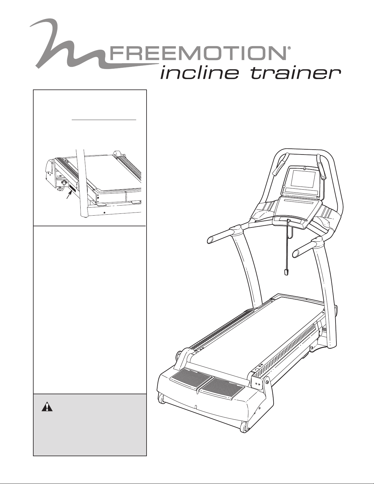
Model No. FMTK7256P.3/
FMTK7506P.3
Serial No.
Write the serial number in the
space above for future reference.
Serial
Number
Decal
QUESTIONS?
If you have questions, or if parts
are damaged or missing, please
see HOW TO CONTACT CUSTOMER CARE on the back cover
of this manual.
USERʼS MANUAL
CAUTION
Read all precautions and instructions in this manual before using
this equipment. Keep this manual
for future reference.
www.freemotionfitness.com
Page 2

TABLE OF CONTENTS
MPORTANT PRECAUTIONS . . . . . . . . . . . . . . . . . . . . . . . . . . . . . . . . . . . . . . . . . . . . . . . . . . . . . . . . . . . . . . . . .3
I
WARNING DECAL PLACEMENT . . . . . . . . . . . . . . . . . . . . . . . . . . . . . . . . . . . . . . . . . . . . . . . . . . . . . . . . . . . . . .5
BEFORE YOU BEGIN . . . . . . . . . . . . . . . . . . . . . . . . . . . . . . . . . . . . . . . . . . . . . . . . . . . . . . . . . . . . . . . . . . . . . . .6
ASSEMBLY . . . . . . . . . . . . . . . . . . . . . . . . . . . . . . . . . . . . . . . . . . . . . . . . . . . . . . . . . . . . . . . . . . . . . . . . . . . . . . .7
HOW TO MOVE THE INCLINE TRAINER . . . . . . . . . . . . . . . . . . . . . . . . . . . . . . . . . . . . . . . . . . . . . . . . . . . . . . .11
OW TO CONNECT THE INCLINE TRAINER . . . . . . . . . . . . . . . . . . . . . . . . . . . . . . . . . . . . . . . . . . . . . . . . . . .12
H
HOW TO UPGRADE THE CONSOLE . . . . . . . . . . . . . . . . . . . . . . . . . . . . . . . . . . . . . . . . . . . . . . . . . . . . . . . . . .13
HOW TO USE THE BASIC CONSOLE . . . . . . . . . . . . . . . . . . . . . . . . . . . . . . . . . . . . . . . . . . . . . . . . . . . . . . . . .14
PREVENTIVE MAINTENANCE . . . . . . . . . . . . . . . . . . . . . . . . . . . . . . . . . . . . . . . . . . . . . . . . . . . . . . . . . . . . . . .33
SIX-MONTH PREVENTIVE MAINTENANCE RECORD . . . . . . . . . . . . . . . . . . . . . . . . . . . . . . . . . . . . . . . . . . . .36
TROUBLESHOOTING . . . . . . . . . . . . . . . . . . . . . . . . . . . . . . . . . . . . . . . . . . . . . . . . . . . . . . . . . . . . . . . . . . . . . .37
EXERCISE GUIDELINES . . . . . . . . . . . . . . . . . . . . . . . . . . . . . . . . . . . . . . . . . . . . . . . . . . . . . . . . . . . . . . . . . . .39
PART LIST . . . . . . . . . . . . . . . . . . . . . . . . . . . . . . . . . . . . . . . . . . . . . . . . . . . . . . . . . . . . . . . . . . . . . . . . . . . . . . .42
EXPLODED DRAWING . . . . . . . . . . . . . . . . . . . . . . . . . . . . . . . . . . . . . . . . . . . . . . . . . . . . . . . . . . . . . . . . . . . . .44
HOW TO CONTACT CUSTOMER CARE . . . . . . . . . . . . . . . . . . . . . . . . . . . . . . . . . . . . . . . . . . . . . . . .Back Cover
FREEMOTION is a registered trademark of ICON IP, Inc.
2
Page 3

IMPORTANT PRECAUTIONS
WARNING:
structions in this manual and all warnings on your incline trainer before using your incline trainer.
FreeMotion Fitness assumes no responsibility for personal injury or property damage sustained by
r through the use of this product.
o
1. It is the responsibility of the owner to ensure
that all users of the incline trainer are adequately informed of all warnings and precautions.
2. Use the incline trainer only as described in
this manual.
3. Place the incline trainer on a level surface,
with at least 2.4 m (8 ft.) of clearance behind
it and 0.6 m (2 ft.) on each side. Do not place
the incline trainer on a surface that blocks
any air openings. To protect the floor or carpet from damage, place a mat under the incline trainer.
4. Keep the incline trainer indoors, away from
moisture and dust. Do not place the incline
trainer in a garage or covered patio, or near
water.
5. Do not operate the incline trainer where
aerosol products are used or where oxygen
is being administered.
6. Do not operate the incline trainer until it is
properly and fully assembled (see ASSEMBLY on page 7).
7. Regularly inspect and tighten all parts of the
incline trainer.
8. Keep children under the age of 12 and pets
away from the incline trainer at all times.
To reduce the risk of serious injury, read all important precautions and in-
10. Never allow more than one person on the
incline trainer at a time.
11. Wear appropriate exercise clothes when
using the incline trainer. Do not wear loose
clothes that could become caught in the incline trainer. Athletic support clothes are recommended for both men and women. Always
wear athletic shoes. Never use the incline
trainer with bare feet, wearing only stockings, or in sandals.
12. When connecting the power cord, follow the
instructions on page 12. No other appliance
should be on the same circuit as the incline
trainer. Do not use an extension cord.
13. Keep the power cord away from heated surfaces.
14. Never move the walking belt while the power
is turned off. Do not operate the incline
trainer if the power cord or plug is damaged
or if the incline trainer is not working properly. (See TROUBLESHOOTING on page 37 if
the incline trainer is not working properly.)
15. Read, understand, and test the emergency
stop procedure before using the incline
trainer (see GETTING STARTED on page 17).
16. Never start the incline trainer while you are
standing on the walking belt. Always hold the
handrails while using the incline trainer.
9. The incline trainer should not be used by persons weighing more than 159 kg (350 lbs).
17. The incline trainer is capable of high speeds.
Adjust the speed in small increments to
avoid sudden jumps in speed.
3
Page 4

18. The pulse sensor is not a medical device.
arious factors, including the user's move-
V
ment, may affect the accuracy of heart rate
readings. The pulse sensor is intended only
as an exercise aid in determining heart rate
trends in general.
9. Never leave the incline trainer unattended
1
while it is running.
20. Do not change the incline of the incline
trainer by placing objects under it.
22. Make sure to perform all maintenance proceures outlined in this manual. Failure to do
d
so will void the warranty and may result in
damage to the incline trainer.
23.
DANGER: Always unplug the power
ord before cleaning the incline trainer and
c
before performing the maintenance and adjustment procedures described in this manual. Servicing other than the procedures in
this manual should be performed by an authorized service representative only.
21. Never insert or drop any object into any
opening on the incline trainer.
24. Over exercising may result in serious injury
or death. If you feel faint or if you experience
pain while exercising, stop immediately and
cool down.
4
Page 5
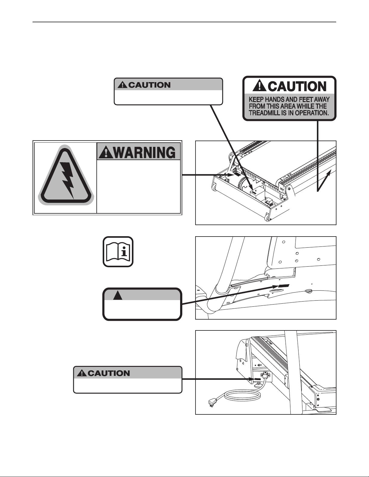
HAZARDOUS
VOLTAGE
Disconnect power
before servicing.
Do not remove or insert this plug while the
safety key is inserted in the console. Touch
metal frame before removing or inserting plug.
Static sensitive components may be affected.
WARNING
!
:
HIGH VOLTAGE
Disconnect line cord from
outlet before servicing.
:
HIGH VOLTAGE
Disconnect line cord from
outlet before servicing.
WARNING DECAL PLACEMENT
hese drawings show the location(s) of the warning decal(s). If a decal is missing or illegible, see the back
T
cover of this manual and request a free replacement decal. Apply the decal in the location shown.
Note: The decal(s) may not be shown at actual size.
Note: There
is one decal
on each side
5
Page 6
BEFORE YOU BEGIN
Thank you for selecting the revolutionary
FREEMOTION®INCLINE TRAINER. The INCLINE
TRAINER provides an impressive selection of features
esigned to make your workouts at home more effec-
d
tive and enjoyable.
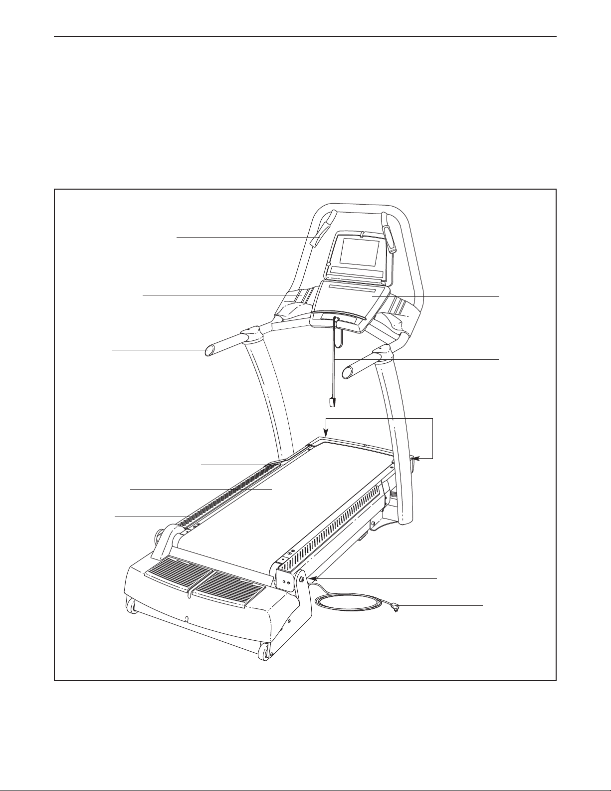
For your benefit, read this manual carefully before
you use the incline trainer. If you have questions
Handgrip Pulse Sensor
Accessory Tray
Handrail
after reading this manual, please see the back cover of
this manual. To help us assist you, note the product
model number and serial number before contacting us.
he model number and the location of the serial num-
T
ber decal are shown on the front cover of this manual.
Before reading further, please familiarize yourself with
the parts that are labeled in the drawing below.
Console
Key/Clip
Cushioned Walking Platform
Walking Belt
Foot Rail
Roller Adjustment Bolts
On/Off Circuit Breaker
Power Cord
6
Page 7
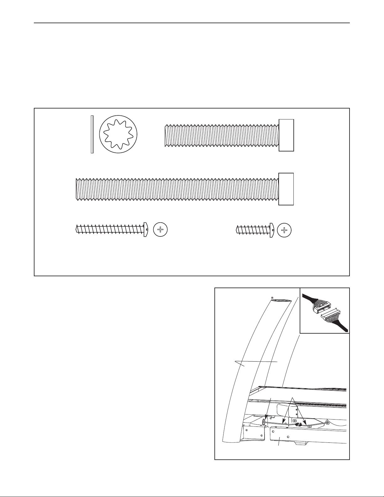
Console Plate Screw
(94)–4*
Display Mounting Screw
(114)–5*
*These Screws are included only with the Workout TV console INCLINE TRAINER.
1/2" Star
Washer (124)–4
Side Base Bolt (95)–4
Top Base Bolt (96)–4
ASSEMBLY
Assembly requires two persons. Set the incline trainer in a cleared area and remove all packing materials. Do
not dispose of the packing materials until assembly is completed. Assembly can be completed using a 3/8"
ex key, a 7/32" hex key, and a Phillips screwdriver.
h
For help identifying assembly hardware, see the drawings below. Note: If a part is not found in the hardware
kit, check to see if the part has been preattached. To avoid damaging plastic parts, do not use power
tools for assembly.
1. Place the Uprights (93) near the front of the Base Frame
(56) as shown.
Connect the indicated wires on the right side of the incline trainer. See the inset drawing. The connectors
should slide together easily and snap into place. If
they do not, turn one connector and try again. IF THE
CONNECTORS ARE NOT INSERTED PROPERLY,
THE CONSOLE MAY BE DAMAGED WHEN THE
POWER IS TURNED ON.
Insert the excess wire into the indicated hole in the
Upright (93).
1
93
Hole
LEFT
7
RIGHT
Wires
56
Page 8
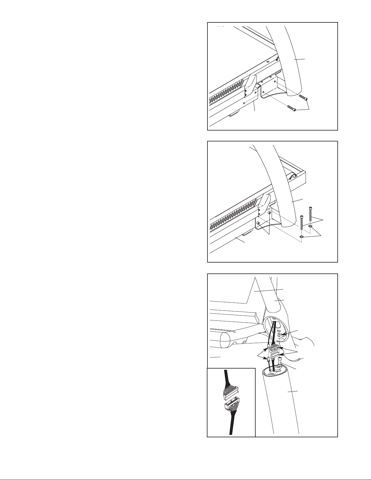
2. Slide the Uprights (93) onto the Base Frame (56), and
align the holes in the Uprights with the holes in the Base
Frame. Be careful to avoid pinching the wires. Finger
ighten two Side Base Bolts (95) through the bracket
t
near the right Upright and into the Base Frame; do not
ighten the Side Base Bolts yet.
t
Repeat this step on the left side of the incline
trainer; there are no wires on the left side.
2
93
3. Finger tighten two Top Base Bolts (96) with two 1/2" Star
Washers (124) through the top of the bracket near the
right Upright (93) and into the Base Frame (56); do not
tighten the Top Base Bolts yet.
Repeat this step on the left side of the incline
trainer.
Then, tighten the Top Base Bolts (96) and the Side Base
Bolts (95) on both sides.
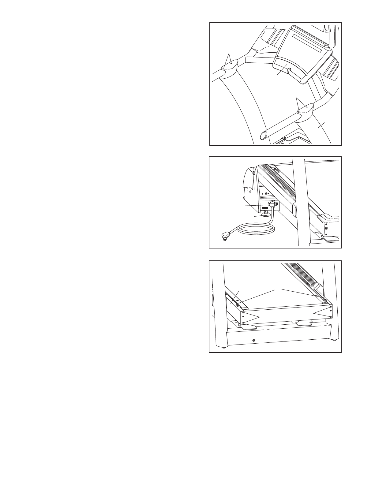
4. Locate the Bolt (B) on the top of each Upright (93). With
the help of a second person, set the console assembly
onto the top of the Uprights. Make sure that the Bolts
are inserted into the indicated holes in the bottom of
the console assembly (only one side is shown). Be
careful not to pinch any wires. Pull up on the Handrail
(103) and carefully tip the console assembly forward so
that you can see the indicated wires. Make sure the
console assembly is held securely by the Bolts.
56
3
95
56
4
Console
Assembly
103
95
93
96
124
Hole
Connect the wire in the right Upright (93) and the wire in
the console assembly. See the inset drawing. The
connectors should slide together easily and snap
into place. If they do not, turn one connector and try
again. IF THE CONNECTORS ARE NOT INSERTED
PROPERLY, THE CONSOLE MAY BE DAMAGED
WHEN THE POWER IS TURNED ON. If there is a TV
cable, connect the TV cable in the console assembly to
the TV cable in the right Upright. Then, insert the wires
down into the right Upright.
8
TV Cables
Wires
B
93
Page 9
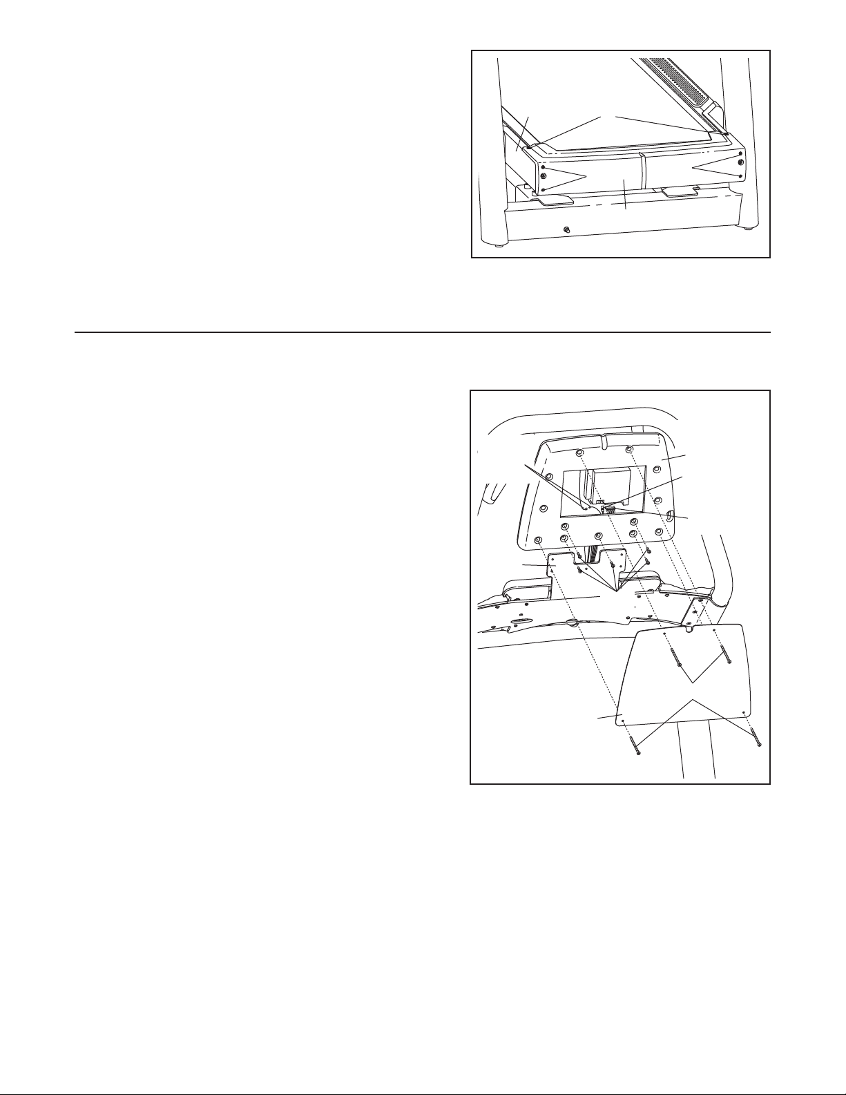
5. With the help of a second person, pivot the console assembly to the position shown. Be careful to avoid
pinching your hands or the wires.
5
Align the Handrail Bolts (102) with the holes in the tops
f the Uprights (93). Start all four Handrail Bolts, and
o
then firmly tighten them.
6. After the incline trainer is placed in the location where it
will be used (see HOW TO MOVE THE INCLINE
TRAINER on page 11), make sure that both Rear
Leveling Feet (38) and the Base Pads (not shown) rest
firmly on the floor. If the incline trainer rocks even
slightly, turn the right Rear Leveling Foot clockwise or
counterclockwise until the rocking motion is eliminated.
Note: The Power Cord Bracket (64) must be attached
at all times.
102
Console
ssembly
A
102
93
6
64
38
7. Remove the two Cover Screws (2) and the four Front
Cover Screws (16) from the Frame (22).
7
22
16
2
16
9
Page 10
8. Attach the Front Cover (17) to the Frame (22) with the
two Cover Screws (2) and the four Front Cover Screws
(16).
8
22
2
6
1
17
9. Make sure that all parts are properly tightened before you use the incline trainer. To protect the floor or
carpet, place a mat beneath the incline trainer.
If you purchase the Workout TV console, follow the steps below to assemble the console.
1. Unplug the power cord. Remove the four Console
Plate Screws (94) and the Basic Console Plate (not
shown). Remove the five #8 x 3/4" Screws (85) from the
back of the Basic Console (not shown), and remove the
Basic Console from the incline trainer. Disconnect all
wires connecting the Basic Console to the incline trainer.
2. Insert the wire harness, the TV cable, and the ground
wire into the bottom of the TV Console Assembly (A) as
you slide the TV Console Assembly onto the bracket on
the Handrail (103). Connect the wire harness, the TV
cable, and the ground wire to the back of the TV
Console Assembly. Make sure to connect the connec-
tors properly.
Ground
Wires
103
85
16
A
TV Cable
Wire
Harness
Align the indicated five holes in the back of the TV
Console Assembly (A) with the five holes in the bracket
on the Handrail (103). Attach the TV Console Assembly
with five #8 x 3/4" Screws (85). Be careful not to pinch
any wires.
Attach the TV Console Plate (118) to the TV Console
Assembly (A) with four Console Plate Screws (94).
94
118
10
Page 11
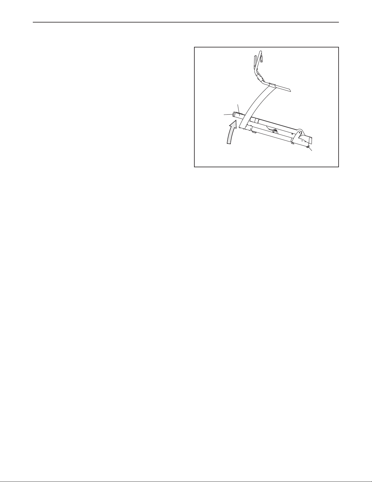
HOW TO MOVE THE INCLINE TRAINER
Before moving the incline trainer, unplug the power
cord. Note: It may be necessary to disconnect a CATV
cable and a network wire from the incline trainer, depending on how far the incline trainer will be moved.
Due to the size and weight of the incline trainer,
moving it requires two or three persons. Hold the
metal frame firmly in the location shown at the right.
CAUTION: To decrease the possibility of damage to
the incline trainer or of injury, do not lift the frame
by the plastic front cover. Carefully roll the incline
trainer on the wheels to the desired location and then
lower it back to the level position. CAUTION: To reduce
the risk of injury, use extreme caution while moving
the incline trainer. Do not attempt to move the incline trainer over uneven surfaces.
Front
Cover
Frame
Wheels
11
Page 12
HOW TO CONNECT THE INCLINE TRAINER
HOW TO CONNECT THE POWER CORD IN THE UK
DANGER: Improper connection of
the equipment-grounding conductor can result
n an increased risk of electric shock. Check
i
with a qualified electrician or serviceman if
you are in doubt as to whether the product is
properly grounded. Do not modify the plug
provided with the product—if it will not fit the
outlet, have a proper outlet installed by a qualified electrician. Do not use an adapter to connect the plug to an improper receptacle.
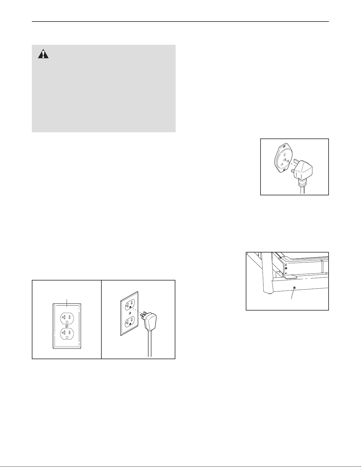
HOW TO CONNECT THE POWER CORD IN THE
UNITED STATES
This product must be grounded. If it should malfunc-
tion or break down, grounding provides a path of least
resistance for electric current to reduce the risk of electric shock.
This product must be earthed. If it should malfunc-
ion or break down, earthing provides a path of least
t
resistance for electric current to reduce the risk of elec-
ric shock.
t
This product is for use on a dedicated, 10-amp,
240-volt circuit. No other appliance should be on
the same circuit. The product is equipped with a cord
having an equipment-earthing conductor and an earthing plug.
Plug the earthing plug
into a receptacle as
shown at the right. Do
not modify the plug or
the receptacle. Do not
use an adapter or an extension cord. The receptacle must be earthed.
This product is for use on a dedicated, 20-amp,
120-volt circuit. No other appliance should be on
the same circuit. This product is equipped with a cord
having an equipment-grounding conductor and a
grounding plug.
Plug the grounding plug into a standard NEMA 5-20
receptacle. Do not modify the plug or the receptacle.
Do not use an adapter, a surge protector, or an extension cord. The receptacle must be grounded.
NEMA 5-20
Receptacle
HOW TO CONNECT A CATV CABLE
If your incline trainer has the Workout TV console,
a CATV cable must be connected to the incline trainer
for cable TV stations to be viewed.
Locate the cable
jack on the front of
the incline trainer.
Connect the CATV
cable to the cable
jack (in the UK use
a PAL adapter [not
included]). Route
the cable so that it
will not be pinched
or crushed by the lift mechanism or the frame.
A satellite receiver, VCR, or DVD player can also be
connected to the incline trainer. Connect a CATV cable
from the coaxial output on your equipment (usually labeled TV OUT or RF OUT) to the cable jack on the
front of the incline trainer.
Cable Jack
Note: Audio/video equipment without coaxial outputs
(some satellite receivers and DVD players) will require
an RF modulator to work correctly. RF modulators are
not available from FreeMotion Fitness, but are available at electronics stores. See the owner's manual for
the equipment you wish to connect to determine if an
RF modulator is needed, or contact your local
audio/visual service provider.
12
Page 13
F
SA
HOW TO UPGRADE THE CONSOLE
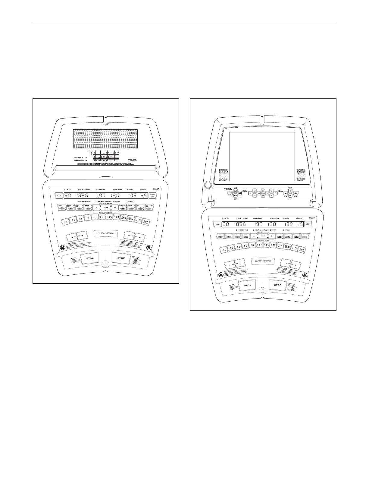
Your incline trainer has been pre-configured to operate with the Basic console or the Workout TV console (see
the drawings below). To learn about the features of the Basic console, see page 14. To learn about the features
f the Workout TV console, see the userʼs manual included with the Workout TV console.
o
o upgrade your console and expand the capabilities of the incline trainer whenever you choose, please
T
see the back cover of this manual.
Basic Console
Workout TV Console
13
Page 14
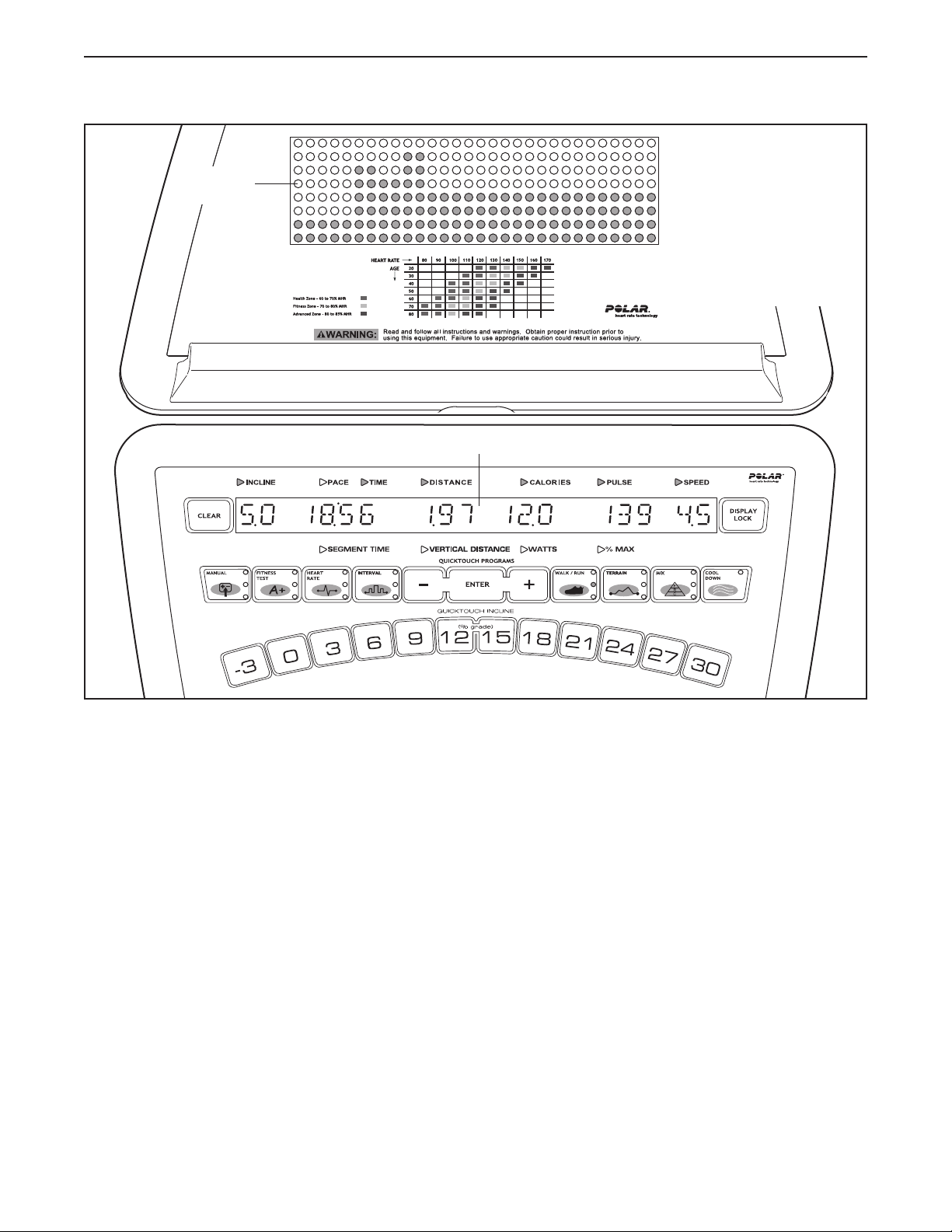
HOW TO USE THE BASIC CONSOLE
atrix
M
Main Display
Note: If there is a
sheet of clear plastic
on the face of the
onsole, remove it.
c
FEATURES OF THE CONSOLE
The Basic console offers an impressive array of features designed to help you get the greatest benefits
from your exercise.
When the QUICK START mode is selected, the speed
and incline of the incline trainer can be changed with
the touch of a button. As you exercise, the console will
provide continuous exercise feedback. You can even
measure your heart rate using the built-in pulse sensor.
In addition, the console offers a wide selection of workout programs. Each program automatically controls the
speed and/or incline of the incline trainer to give you
an effective workout.
The console also offers three HEART RATE programs
that adjust the speed and incline of the incline trainer
to keep your heart rate near target levels during your
workouts, and three unique FITNESS TEST programs
that measure your relative fitness level. Note: The
HEART RATE programs and the FITNESS TEST programs require the use of a Polar
pulse sensor (not included).
Before using the incline trainer, please read
OVERVIEW OF THE CONSOLE beginning on page
15. To use the QUICK START mode, see page 17.
To use a MANUAL program, see page 18. To use a
FITNESS TEST program, see page 20. To use a
HEART RATE program, see page 22. To use an INTERVAL program, see page 24. To use a
WALK/RUN program, see page 26. To use a TERRAIN program, see page 27. To use a FITNESS or
RANDOM program, see page 28. To use a CUSTOM
program, see page 29. To use the maintenance
mode, see page 30.
®
-compatible chest
14
Page 15
OVERVIEW OF THE CONSOLE
For your benefit, please read all of the instructions
n pages 15 and 16 before you use the incline
o
trainer.
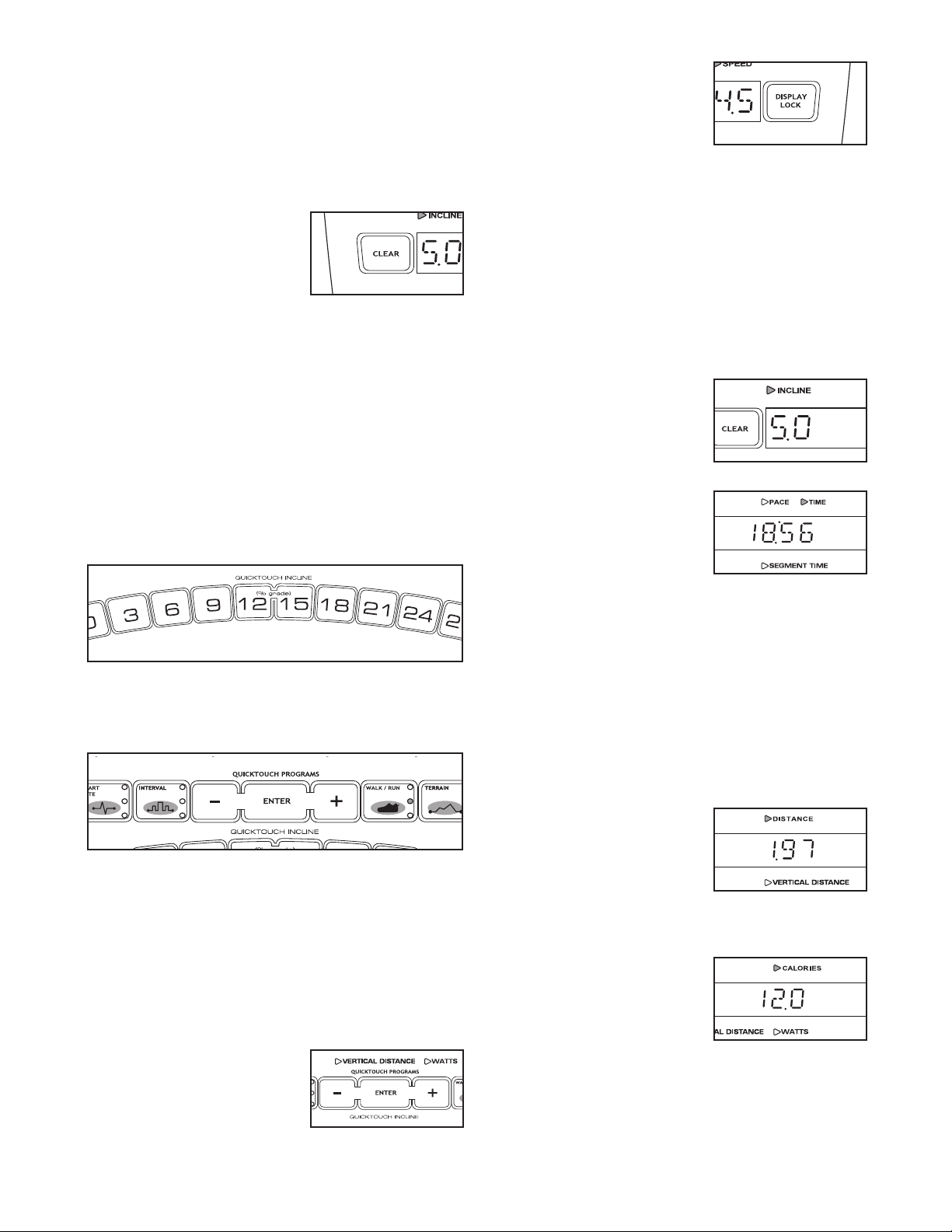
THE BUTTONS
The CLEAR button—This
button is used to reset the
console. When this button is
pressed, the main display
will be reset and the words
SELECT PROGRAM TO
BEGIN will appear in the main display. Note: If one
program is started and then a different program is selected, the main display will not be reset unless the
CLEAR button is pressed before the second program
is selected.
The QUICKTOUCH INCLINE buttons—These buttons control the incline of the walking belt. To change
the incline quickly, press the QUICKTOUCH INCLINE
buttons. Note: After the buttons are pressed, it may
take a moment for the incline trainer to reach the selected incline setting.
The QUICKTOUCH PROGRAMS buttons—These
buttons are used to select the various programs.
The DISPLAY LOCK
button—This button can be
used during your workout to
eep the main display from
k
scanning from one number to
he next every few seconds.
t
Each time the DISPLAY LOCK button is pressed during your workout, the word LOCKED or UNLOCKED
will briefly appear in the main display.
THE MAIN DISPLAY
The main display will display a variety of text messages to guide you through your workouts. In addition,
the main display will display the following information
while you exercise:
Incline—The left end of the
main display will show the incline setting of the incline
trainer.
Pace/Time/Segment Time—
When the QUICK START
mode, the MANUAL VERTICAL DISTANCE program,
the MANUAL CALORIE program, or any of the
WALK/RUN programs are selected, this section of the
main display will show your pace, in minutes per mile
or minutes per kilometer, the elapsed time, and the
elapsed time in the current segment. The display will
change from one number to the next every few seconds. When any other program is selected, the main
display will show your pace, the time remaining in the
program, and the time remaining in the current segment of the program. The display will change from one
number to the other every few seconds.
The COOL DOWN button—This button is designed to
help you cool down after a workout. When you press
the COOL DOWN button, the speed of the walking belt
will automatically adjust to 3 mph (or 4.8 kph) and the
incline will adjust to 0% for a three-minute cool-down
walk. Note: If the walking belt is already moving at less
than 3 mph (or 4.8 kph), the speed of the walking belt
will not change.
The ENTER button and +
and – buttons—These but-
tons are used to enter information into the console.
Distance/Vertical
Distance—This section of
the main display will show
the distance that you have
walked or run, in miles or
kilometers, and the number
of vertical feet you have climbed.
Calories/Watts—This section of the main display will
show the approximate number of calories you have
burned and your power output in watts. The display will
change from one number to the other every few seconds.
15
Page 16

Pulse/% Max—When you
use the handgrip pulse sensor or a Polar®-compatible
hest pulse sensor (not in-
c
cluded), this section of the
ain display will show your
m
heart rate. When a HEART RATE program is selected,
the display will show your heart rate and the corresponding percentage of your age-predicted maximum
heart rate (see step 7 on page 22 for an explanation of
your age-predicted maximum heart rate). The display
will change from one number to the other every few
seconds. Note: The display will only show the percentage of your age-predicted maximum heart rate if you
have entered your age.
Speed—The right end of the
main display will show the
speed of the walking belt, in
miles per hour or kilometers
per hour.
THE PULSE SENSOR
If there are sheets of
clear plastic on the
metal contacts on the
pulse sensor, peel off
the plastic. To mea-
sure your heart rate,
stand on the foot rails
and hold the contacts
with both hands; your
palms must be resting on the upper contacts, and your
fingers must be touching the lower contacts. Avoid
moving your hands. When your pulse is detected, the
PULSE indicator above the main display will begin to
flash, and then your heart rate will be shown. For the
most accurate heart rate reading, hold the contacts for
at least 15 seconds without moving your hands.
Contacts
CAUTION: Before operating the
console, read the following precautions.
Do not stand on the walking belt when turn-
•
ing on the power.
Always wear the clip (see the drawing on
•
page 17) while operating the incline trainer.
• Adjust the speed in small increments to
avoid sudden jumps in speed.
• The pulse sensor is not a medical device.
Various factors may affect the accuracy of
heart rate readings. The pulse sensor is intended only as an exercise aid in determining heart rate trends in general.
• If you have heart problems, or if you are over
60 years of age and have been inactive, do
not use the HEART RATE or FITNESS TEST
programs. If you are taking medication regularly, consult your physician to find whether
the medication will affect your exercise heart
rate.
• To reduce the possibility of electric shock,
keep the console dry. Avoid spilling liquids
on the console and place only a sealed water
bottle in the water bottle holder.
If your heart rate is not shown, make sure that your
hands are positioned as described. Be careful not to
move your hands excessively or to squeeze the contacts too tightly. For optimal performance, clean the
contacts using a soft cloth; never use alcohol, abrasives, or chemicals.
16
Page 17

GETTING STARTED
HOW TO USE THE QUICK START MODE
1. Plug in the power cord.
See HOW TO CONNECT THE POWER CORD on
age 12.
p
2. Move the on/off circuit breaker to the “on”
position.
Locate the on/off
circuit breaker on
the incline trainer
near the power
cord. Switch the
on/off circuit
breaker to the
“on” position.
3. Insert the key into the console.
Note: The console can be set to be used without
the key. See page 32 for instructions. If the console has been set to be used without the key, this
step does not apply.
Find the key and the clip
on the console and attach the clip to the waistband of your clothes.
Next, insert the key into
the console. IMPOR-
TANT: In an emergency
situation, the key can be pulled from the console, causing the walking belt to slow to a stop.
Test the clip by carefully taking a few steps
backward; if the key is not pulled from the console, adjust the position of the clip.
Insert the key into the console again. After a moment, various displays and indicators on the console will light.
“On”
Position
Key
Clip
If you do not plan to use a program, the QUICK
TART mode will allow you to simply start exercising
S
and adjust the speed and incline of the incline trainer
anually.
m
1. Insert the key into the console.
See GETTING STARTED at the left.
2. Select the QUICK START mode.
To select the QUICK START mode, press the
QUICK START button.
A moment after the button is pressed, the walking
belt will begin to move at 1 mph. Hold the handrails
and begin walking.
3. Change the speed and incline as desired.
As you exercise, change the speed of the walking
belt as desired by pressing the SPEED + and –
buttons. Each time a button is pressed, the speed
setting will change by 0.1 mph; if a button is held
down, the speed setting will change in rapid increments. Note: After the buttons are pressed, it may
take a moment for the incline trainer to reach the
selected speed setting.
To change the incline of the incline trainer, press
the INCLINE + and – buttons. Each time a button
is pressed, the incline will change by 0.5%. Note:
After the buttons are pressed, it may take a moment for the incline trainer to reach the selected incline setting.
To change the incline quickly, press the QUICKTOUCH INCLINE buttons. Note: After the buttons
are pressed, it may take a moment for the incline
trainer to reach the selected incline setting.
17
Page 18

4. Follow your progress with the matrix and the
main display.
he matrix will show your progress and the incline
T
settings that you select. When you begin exercis-
ng, the left column of the matrix will begin to flash.
i
After 30 seconds, a tone will sound and the column
to the right will begin to flash.
Flashing Column
Each time you change the incline of the walking
belt, additional indicators will light or darken in the
flashing column, and in all columns to the right of
the flashing column.
HOW TO USE A MANUAL PROGRAM
The MANUAL TIME program allows you to enter a
ime goal for your workout. The program will then
t
count down the time remaining in your workout as you
ontrol the speed and incline of the incline trainer.
c
The MANUAL VERTICAL DISTANCE program allows
you to enter a vertical distance goal for your workout.
The program will calculate the vertical distance you
have walked or run in your workout as you control the
speed and incline of the incline trainer.
The MANUAL CALORIE program allows you to enter a
calorie-burning goal for your workout. The program
calculates the calories you have burned in your workout as you control the speed and incline of the incline
trainer.
1. Insert the key into the console.
See GETTING STARTED on page 17.
After every 30 seconds that you exercise, a tone
will sound and the next column to the right will
begin to flash. When you have exercised for 7 1/2
minutes, the same column will continue to flash,
and all columns of indicators will shift one position
to the left. The columns of indicators will continue
to shift to the left after every 30 seconds, until you
are finished exercising.
See THE MAIN DISPLAY on page 15.
5. Measure your heart rate if desired.
See THE PULSE SENSOR on page 16.
6. When you are finished exercising, stop the
walking belt and remove the key.
Step onto the foot rails and press the STOP button.
Next, remove the key from the console and put the
key in a secure place.
When the incline trainer is not in use, switch the
on/off circuit breaker near the power cord to the off
position and unplug the power cord.
2. Select a MANUAL program.
Press the MANUAL button one, two, or three times
to select the MANUAL TIME, MANUAL VERTICAL
DISTANCE, or MANUAL CALORIE program. The
name of the program will appear in the main display. The words ENTER AGE and the current age
setting will then be shown.
3. Enter your age.
A moment after the program is selected, the words
ENTER AGE and an age setting of 35 will appear
in the main display. To enter your age, press the +
and – buttons beside the ENTER button; hold
down the buttons to enter your age quickly. When
your age is shown, press the ENTER button.
18
Page 19

4. Enter your weight.
Next, the words ENTER WEIGHT and a weight
etting of 185 pounds will appear in the main dis-
s
play. To enter your weight, press the + and – but-
ons beside the ENTER button; hold down the but-
t
tons to enter your weight quickly. When your
weight is shown, press the ENTER button.
To stop the walking belt, press the STOP button.
The time will begin to flash in the main display. To
restart the walking belt, press the QUICK START
utton or the SPEED + button and then adjust the
b
speed as desired.
7. Change the incline of the incline trainer as desired.
5. Enter a program goal.
If you have selected the MANUAL TIME program,
the words ENTER TIME and a time setting of 15
minutes will appear in the main display. To change
the length of time that the program will last, press
the + and – buttons beside the ENTER button.
Then, press the ENTER button.
If you have selected the MANUAL VERTICAL DISTANCE program, the words ENTER VERTICAL
DISTANCE and a vertical distance setting of 500
feet will appear in the main display. To change the
vertical feet you want to walk or run during your
workout, press the + and – buttons beside the
ENTER button. Then, press the ENTER button.
If you have selected the MANUAL CALORIE program, the words ENTER CALORIES and a calorieburning goal setting of 100 calories will appear in
the main display. To change the approximate number of calories that you want to burn during your
workout, press the + and – buttons beside the
ENTER button. Then, press the ENTER button.
6. Press the QUICK START button to start the program.
To change the incline of the incline trainer, press
the INCLINE + and – buttons. Each time a button
is pressed, the incline will change by 0.5%. To
change the incline quickly, press the QUICKTOUCH INCLINE buttons. Note: After the buttons
are pressed, it may take a moment for the incline
trainer to reach the selected incline setting.
8. Follow your progress with the matrix and the
main display.
See step 4 on page 18.
9. Measure your heart rate if desired.
See THE PULSE SENSOR on page 16.
10. When the program is completed, remove the
key.
Step onto the foot rails. Remove the key from the
console and put the key in a secure place.
When the incline trainer is not in use, switch the
on/off circuit breaker near the power cord to the off
position and unplug the power cord.
A moment after the button is pressed, the walking
belt will begin to move at 1 mph. Hold the handrails
and begin walking.
As you exercise, change the speed of the walking
belt as desired by pressing the SPEED + and –
buttons. Each time a button is pressed, the speed
setting will change by 0.1 mph; if a button is held
down, the speed setting will change in rapid increments. Note: After the buttons are pressed, it may
take a moment for the incline trainer to reach the
selected speed setting.
19
Page 20

HOW TO USE A FITNESS TEST PROGRAM
3. Select a FITNESS TEST program.
The FITNESS TEST programs measure your approxi-
ate VO
m
ax, or aerobic capacity. VO
2 m
2 m
ax is a
measure of your ability to take in and utilize oxygen to
enerate energy for endurance activities such as run-
g
ning and cycling. In technical terms, VO
2 max is the
maximum volume of oxygen, in milliliters, that your
body can use in one minute, per kilogram of body
weight. A high VO2 max indicates a high level of cardiorespiratory fitness. Note: To learn more about VO2
max, refer to a reputable book or consult your physician.
For the most accurate results, use a FITNESS TEST
program when you are not feeling tired, when you
have not eaten for at least two hours, and when you
have not exercised for at least 24 hours.
The GERKIN FITNESS TEST is completed when your
heart rate stays greater than 85% of your age-predicted maximum heart rate for 15 seconds, or when
the program reaches 11 minutes. Note: The GERKIN
FITNESS TEST begins with a 3-minute warm-up.
The EBBELING FITNESS TEST is completed in 9 minutes.
Press the FITNESS TEST button one, two, or three
imes to select the GERKIN FIT TEST, the EBBEL-
t
ING FIT TEST, or the FREEMOTION FIT TEST.
When a FITNESS TEST program is selected, the
name of the FITNESS TEST will appear in the
main display. The words ENTER AGE and the current age setting will then be shown.
During a FITNESS TEST program, the matrix will
show a moving graphic that represents your heart
rate. Each time a heartbeat is detected, an additional peak will appear in the graphic.
The FREEMOTION FITNESS TEST is completed
when your heart rate reaches greater than 70% of your
age-predicted maximum heart rate, or when the program reaches 30 minutes.
Follow the steps below to use a FITNESS TEST program.
1. Put on a Polar®-compatible chest pulse sensor
(not included).
You must wear a chest pulse sensor to use a
FITNESS TEST program.
2. Insert the key into the console.
See GETTING STARTED on page 17.
4. Enter your age.
See step 3 on page 18.
5. Enter your weight.
See step 4 on page 19.
If you have selected the EBBELING FITNESS
TEST, continue to step 6. If you have selected
the GERKIN FITNESS TEST or the FREEMOTION FITNESS TEST, skip to step 7.
20
Page 21

6. Enter your gender.
If you selected the EBBELING FITNESS TEST,
ou will be prompted to enter your gender. Either
y
the word MALE or the word FEMALE will appear in
he main display. To enter your gender, press the +
t
and – buttons beside the ENTER button. When
your gender is shown, press the ENTER button.
7. Press the QUICK START button to start the program.
A moment after the button is pressed, the incline
trainer will automatically adjust to the first speed
and incline settings for the program. Hold the
handrails and begin walking.
Each FITNESS TEST is divided into several segments of different lengths. One speed setting and
one incline setting are programmed for each segment. The console will guide you through the FITNESS TEST and record your heart rate input to determine your relative fitness level.
When the EBBELING FITNESS TEST is completed, the walking belt will slow to a stop and your
VO2 max will be shown in the main display.
When the FREEMOTION FITNESS TEST is com-
leted, the walking belt will slow to a stop and your
p
2 max and your fitness level will be shown in the
VO
main display. Note: There are ten fitness levels; fitness level 10 is the highest.
Note: The SPEED and INCLINE buttons will not
function while a FITNESS TEST program is selected. If your pulse is not detected during the program, the letters PLS will flash in the main display.
If this occurs, try the program again on another
day. Make sure that you are wearing a chest pulse
sensor as described in step 1 on page 20.
The FITNESS TEST programs cannot be stopped
temporarily and then restarted. However, the programs can be stopped at any time with the STOP
button. The main display will then show the words
FIT TEST ABORTED.
When the GERKIN FITNESS TEST is completed,
the walking belt will slow to a stop and your VO
2
max and your fitness level will be shown in the
main display. Note: There are 11.4 fitness levels;
fitness level 11.4 is the highest.
8. When the program is completed, remove the
key.
See step 10 on page 19.
21
Page 22

HOW TO USE A HEART RATE PROGRAM
4. Enter your age.
HEART RATE programs automatically control the
peed and incline of the incline trainer to keep your
s
heart rate near a target level while you exercise.
ollow the steps below to use a HEART RATE pro-
F
gram.
®
1. Put on a Polar
-compatible chest pulse sensor
(not included).
You must wear a chest pulse sensor to use a
HEART RATE program.
2. Insert the key into the console.
See GETTING STARTED on page 17.
3. Select a HEART RATE program.
Press the HEART RATE button one, two, or three
times to select the CONSTANT HEART RATE,
VARIABLE HEART RATE, or FAT BURN program.
Note: The CONSTANT HEART RATE program will
keep your heart rate near a percentage that you
select. The VARIABLE HEART RATE program will
keep your heart rate within a target range during
your workout. The FAT BURN program will keep
your heart rate near 65% of your age-predicted
maximum heart rate (see step 7 at the right for an
explanation of your age-predicted maximum heart
rate).
See step 3 on page 18.
5. Enter your weight.
See step 4 on page 19.
If you have selected the VARIABLE HEART
RATE program, continue to step 6. If you have
selected the CONSTANT HEART RATE program, skip to step 7. If you have selected the
FAT BURN program, skip to step 8.
6. Enter a minimum target heart rate setting.
The words MIN PERCENT and the minimum target
heart rate setting for the program will be shown in
the main display. If desired, you can change the
minimum target heart rate setting by pressing the +
and – buttons beside the ENTER button. The buttons can be held down to change the minimum
heart rate setting quickly. Then, press the ENTER
button.
7. Enter a target heart rate setting.
The words MAX PERCENT and the target heart
rate setting for the program will be shown in the
main display. The target heart rate setting represents a percentage of your age-predicted maxi-
mum heart rate. Your age-predicted maximum
heart rate is 220 minus your age. For example, if
you are 30 years old, your age-predicted maximum
heart rate is 190 beats per minute (220 – 30 =
190). If you are 30 years old, a target heart rate
setting of 50 is equal to 95 beats per minute (50%
of 190 is 95).
When a HEART RATE program is selected, the
name of the program will appear in the main display. The words ENTER AGE and the current age
setting will then be shown.
During HEART RATE programs, the matrix will
show a moving graphic that represents your heart
rate. Each time a heartbeat is detected, an additional peak will appear in the graphic.
If desired, you can change the target heart rate
setting by pressing the + and – buttons beside the
ENTER button. The buttons can be held down to
change the target heart rate setting quickly. The
target heart rate setting can be from 45% to 85% of
your age-predicted maximum heart rate. Then,
press the ENTER button.
22
Page 23

8. Enter a program time.
The words ENTER TIME and a time setting of 15
inutes will appear in the main display. To change
m
the length of time that the program will last, press
he + and – buttons beside the ENTER button.
t
Then, press the ENTER button.
9. Press the QUICK START button to start the program.
A moment after the button is pressed, the incline
trainer will automatically adjust to the first speed
and incline settings for the program. Hold the
handrails and begin walking.
Each HEART RATE program is divided into 30second segments. (The main display will show
both the time remaining in the program and the
time remaining in the current segment of the program.) One target heart rate setting is programmed
for each segment. (During the CONSTANT HEART
RATE program, the same target heart rate setting
will be programmed for all segments.)
next segment. The speed and/or incline setting will
flash in the main display to alert you before the
speed and/or incline changes. The program will
ontinue until no time remains in the program. The
c
walking belt will then slow to a stop.
Note: The SPEED and INCLINE buttons will not
function while a HEART RATE program is selected. If your pulse is not detected during the program, the letters PLS will flash in the main display
and the speed and incline of the incline trainer may
automatically decrease until your pulse is detected.
If this occurs, see the instructions included with
your chest pulse sensor.
To stop the program at any time, press the STOP
button. HEART RATE programs should not be
stopped temporarily and then restarted. To use a
HEART RATE program again, reselect the program and start it at the beginning.
10. Follow your progress with the main display.
See THE MAIN DISPLAY on page 15.
When only four seconds remain in the first segment of the program, a series of tones will sound
and then the speed and/or incline of the incline
trainer will change, if needed, to bring your heart
rate closer to the target heart rate setting for the
11. When the program is completed, remove the
key.
See step 10 on page 19.
23
Page 24

HOW TO USE AN INTERVAL PROGRAM
6. Enter a minimum incline setting.
The INTERVAL programs will automatically adjust the
ncline of the walking belt as they guide you through an
i
effective interval training workout.
1. Insert the key into the console.
See GETTING STARTED on page 17.
2. Select an INTERVAL program.
Press the INTERVAL button one, two, or three
times to select the INTERVAL 1 TO 1, INTERVAL
1 TO 2, or INTERVAL 1 TO 3 program. When an
INTERVAL program is selected, the name of the
program will appear in the main display. The words
ENTER AGE and the current age setting will then
be shown.
When an INTERVAL program is selected, the matrix will show a graph representing the incline settings for the program.
The words MIN INCLINE and the minimum incline
etting will appear in the main display. To enter the
s
minimum incline you want to walk or run during
our workout, press the + and – buttons beside the
y
ENTER button; hold down the buttons to enter the
minimum incline quickly. Then press the ENTER
button.
7. Enter a maximum incline setting.
The words MAX INCLINE and the maximum incline
setting will appear in the main display. To enter the
maximum incline you want to walk or run during
your workout, press the + and – buttons beside the
ENTER button; hold down the buttons to enter the
maximum incline quickly. Then press the ENTER
button.
8. Press the QUICK START button to start the program.
A moment after the button is pressed, the walking
belt will begin to move at 3 mph and the incline
trainer will automatically adjust to the first incline
setting for the program. Hold the handrails and
begin walking.
3. Enter your age.
See step 3 on page 18.
4. Enter your weight.
See step 4 on page 19.
5. Enter a program time.
See step 8 on page 23.
Each program is divided into several time segments of different lengths. The main display will
show both the time remaining in the program and
the time remaining in the current segment of the
program. One incline setting is programmed for
each segment. The incline setting for the first segment is shown in the flashing left column of the
matrix. The incline settings for upcoming segments
are shown in the columns to the right.
After every 30 seconds that you exercise, a tone
will sound and the next column to the right will
begin to flash.
Note: If the length of the program exceeds the
number of columns in the matrix, the same column
will continue to flash, and all columns of indicators
will shift one position to the left once you have exercised for 7 1/2 minutes. The columns of indicators will continue to shift to the left after every 30
seconds, until you are finished exercising.
24
Page 25

Note: You can manually override the incline setting
for the current segment by pressing the INCLINE
buttons. Every few times an INCLINE button is
ressed, an additional indicator will light or darken
p
in the flashing column. (If any of the columns to the
ight of the flashing column have the same number
r
of lit indicators as the flashing column, an additional indicator may light or darken in those
columns as well.) IMPORTANT: When the next
segment of the program begins, the incline
trainer will automatically adjust to the incline
setting for the next segment.
pressed, the speed will change by 0.1 mph. Note:
After the buttons are pressed, it may take a moment for the walking belt to reach the selected
peed setting.
s
0. Follow your progress with the main display.
1
See THE MAIN DISPLAY on page 15.
11. Measure your heart rate if desired.
See THE PULSE SENSOR on page 16.
To stop the program, press the STOP button. The
time will begin to flash in the main display. To
restart the program, press the QUICK START button.
9. Change the speed of the walking belt as desired.
To change the speed of the walking belt, press the
SPEED + and – buttons. Each time a button is
12. When the program is completed, remove the
key.
See step 10 on page 19.
25
Page 26

HOW TO USE A WALK/RUN PROGRAM
4. Enter your weight.
The 5K program is designed to help you train for a 5K
ace.
r
he 10K program is designed to help you train for a
T
10K race.
The CROSS COUNTRY program is designed to help
you train for a race of a length of your choice.
1. Insert the key into the console.
See GETTING STARTED on page 17.
2. Select a WALK/RUN program.
Press the WALK/RUN button one, two, or three
times to select the 5K, 10K, or CROSS COUNTRY
program. When a WALK/RUN program is selected,
the name of the program will appear in the main
display. The words ENTER AGE and the current
age setting will then be shown.
See step 4 on page 19.
If you have selected the 5K or 10K program,
kip to step 6. If you have selected the CROSS
s
COUNTRY program, continue to step 5.
5. Enter a distance goal.
If you have selected the CROSS COUNTRY program, the words ENTER DISTANCE and a distance setting of 10 miles will appear in the main
display. To change the distance you want to walk
or run during your workout, press the + and – buttons beside the ENTER button. Then, press the
ENTER button.
6. Enter a program time.
See step 8 on page 23. Note: The speed of your
workout depends on the program time that you
enter.
7. Press the QUICK START button to start the program.
When a WALK/RUN program is selected, the matrix will show a graph representing the speed settings for the program.
3. Enter your age.
See step 3 on page 18.
A moment after the button is pressed, the walking
belt will begin to move at the calculated start
speed. Hold the handrails and begin walking.
If the speed of the walking belt is too fast or too
slow, you can change it by pressing the SPEED +
and – buttons. Note: This will change the length of
time of your program.
8. Change the incline of the incline trainer as desired.
See step 7 on page 19.
9. Follow your progress with the main display.
See THE MAIN DISPLAY on page 15.
10. Measure your heart rate if desired.
See THE PULSE SENSOR on page 16.
11. When the program is completed, remove the
key.
26
See step 10 on page 19.
Page 27

HOW TO USE A TERRAIN PROGRAM
6. Enter a maximum incline setting.
During the HILL program, the incline of the incline
rainer will depend on the vertical distance goal and
t
the speed setting that you set. The incline will remain
onstant with only minor adjustments throughout the
c
program to help you reach your vertical distance goal.
During the PEAKS program, the incline will increase
and decrease. The number of times that the incline will
increase and decrease will depend on the maximum
incline setting and the program length that you select.
During the ALL-TERRAIN program, the incline will
sharply increase and then sharply decrease repeatedly. The number of times that the incline will increase
and decrease will depend on the maximum incline setting and the program length that you select.
1. Insert the key into the console.
See GETTING STARTED on page 17.
2. Select a TERRAIN program.
Press the TERRAIN button one, two, or three times
to select the HILL, PEAKS, or ALL-TERRAIN program. When a TERRAIN program is selected, the
name of the program will appear in the main display. The words ENTER AGE and the current age
setting will then be shown. When a TERRAIN program is selected, the matrix will show a graph representing the incline settings for the program.
The words MAX INCLINE and the incline setting
ill appear in the main display. To enter a different
w
maximum incline setting for your workout, press
he + and – buttons beside the ENTER button; hold
t
down the buttons to enter the maximum incline
quickly. Then, press the ENTER button and skip
to step 9.
7. Enter a vertical distance goal.
The words VERTICAL DISTANCE and the vertical
distance goal will appear in the main display. To
enter a different vertical distance goal, press the +
and – buttons beside the ENTER button; hold
down the buttons to enter the goal quickly. Then,
press the ENTER button.
8. Enter a speed setting.
The words ENTER SPEED and the speed setting
will appear in the main display. To enter a different
speed setting, press the + and – buttons beside
the ENTER button; hold down the buttons to enter
the speed quickly. Then, press the ENTER button.
9. Press the QUICK START button to start the program.
3. Enter your age.
See step 3 on page 18.
4. Enter your weight.
See step 4 on page 19.
5. Enter a program time.
See step 8 on page 23.
If you have selected the PEAKS or ALL-TERRAIN program, continue to step 6. If you have
selected the HILL program, skip to step 7.
A moment after the button is pressed, the walking
belt will begin to move at 3 mph for the PEAKS or
ALL-TERRAIN program, or at the speed setting
you entered for the HILL program. Hold the
handrails and begin walking.
If the speed of the walking belt is too fast or too
slow, you can change it by pressing the SPEED +
and – buttons.
10. Follow your progress with the main display.
See THE MAIN DISPLAY on page 15.
11. Measure your heart rate if desired.
See THE PULSE SENSOR on page 16.
12. When the program is completed, remove the
key.
See step 10 on page 19.
27
Page 28

HOW TO USE A FITNESS OR RANDOM PROGRAM
4. Enter your weight.
The FITNESS program controls the speed and incline
f the incline trainer to create a workout with a warm-
o
up period, a steady workout, and a cool-down period.
The RANDOM program creates a different incline program every time it is selected for a variety of workouts.
1. Insert the key into the console.
See GETTING STARTED on page 17.
2. Select the FITNESS program or the RANDOM
program.
Press the MIX button once or twice to select the
FITNESS program or the RANDOM program.
When a FITNESS or RANDOM program is selected, the name of the program will appear in the
main display. The words ENTER AGE and the current age setting will then be shown.
See step 4 on page 19.
If you have selected a RANDOM program, con-
inue to step 5. If you have selected a FITNESS
t
program, skip to step 7.
5. Enter a maximum incline setting.
See step 7 on page 24.
6. Enter a program time.
See step 8 on page 23.
7. Press the QUICK START button to start the program.
A moment after the button is pressed, the walking
belt will begin to move at 5 mph for the FITNESS
program, or at 3 mph for the RANDOM program.
Hold the handrails and begin walking.
The speed of the walking belt will fluctuate between 5 and 8 mph throughout the FITNESS program; the speed of the walking belt will be 3 mph
for the entire RANDOM program.
When a FITNESS program is selected, the matrix
will show a graph representing the speed settings
for the program.
When a RANDOM program is selected, the matrix
will show a graph representing the incline settings
for the program.
3. Enter your age.
See step 3 on page 18.
If the speed of the walking belt is too fast or too
slow, you can change it by pressing the SPEED +
and – buttons.
8. Change the incline of the incline trainer as desired.
See step 7 on page 19.
9. Follow your progress with the main display.
See THE MAIN DISPLAY on page 15.
10. Measure your heart rate if desired.
See THE PULSE SENSOR on page 16.
11. When the program is completed, remove the
key.
See step 10 on page 19.
28
Page 29

HOW TO USE A CUSTOM PROGRAM
1. Insert the key into the console.
See GETTING STARTED on page 17.
2. Select the CUSTOM programs.
To select the CUSTOM programs, press the MIX
button repeatedly. The name of the currently selected CUSTOM program will appear in the main
display. There are three CUSTOM programs. To
select a different CUSTOM program, press the +
and – buttons beside the ENTER button. When
you see the CUSTOM program you want, press
the ENTER button.
Note: The matrix will show the incline settings
of the program. If only three rows of indicators
appear in the matrix, see HOW TO USE THE
MAINTENANCE MODE on page 30, and follow
the instructions to step 6.
3. Enter your age.
See step 3 on page 18.
4. Enter your weight.
See step 4 on page 19.
Each CUSTOM program is divided into several
segments. One speed setting and one incline setting is programmed for each segment. (The same
peed and/or incline setting may be programmed
s
for two or more consecutive segments.) The incline
etting for the first segment is shown in the flashing
s
column of the matrix. The incline settings for the
next several segments are shown in the columns
to the right.
After every 30 seconds that you exercise, a tone
will sound and the next column to the right will
begin to flash.
Note: If the length of the program exceeds the
number of columns in the matrix, the same column
will continue to flash, and all columns of indicators
will shift one position to the left once you have exercised for 7 1/2 minutes. The columns of indicators will continue to shift to the left after every 30
seconds, until you are finished exercising.
To stop the program temporarily, press the STOP
button. The time will begin to flash. To restart the
program, press the QUICK START button.
6. Follow your progress with the main display.
See THE MAIN DISPLAY on page 15.
7. Measure your heart rate if desired.
See THE PULSE SENSOR on page 16.
8. When the program is completed, remove the
key.
5. Press the QUICK START button to start the program.
A moment after the button is pressed, the incline
trainer will automatically adjust to the first speed
and incline settings of the program. Hold the
handrails and begin walking.
See step 10 on page 19.
29
Page 30

HOW TO USE THE MAINTENANCE MODE
The console features a maintenance mode that allows
ou to access information and to view and change var-
y
ious default settings. Follow the steps below to use the
aintenance mode.
m
1. Insert the key into the console.
See GETTING STARTED on page 17.
2. Hold down the ENTER button and the CLEAR
button simultaneously for two seconds to select the maintenance mode.
When the maintenance mode is selected, the
words MAINTENANCE MODE will appear in the
main display. The word HOURS and the total number of hours that the incline trainer has been used
will then be shown.
5. Press the ENTER button again and set the
delay time for the timeout mode.
ny time that the incline trainer is not used for sev-
A
eral minutes, the console will enter a timeout mode
nd the words SELECT PROGRAM TO BEGIN will
a
appear in the main display. To set the number of
seconds before the console will enter the timeout
mode, press the + and – buttons above the
ENTER button. The delay time can be from 15 to
120 seconds.
6. Press the ENTER button again to create the
CUSTOM programs.
The words CUSTOM PROGRAM will appear in the
main display.
3. Press the ENTER button to view the total distance that the walking belt has moved.
4. Press the ENTER button again and set a maximum program time.
To set a maximum program time, press the + and
– buttons beside the ENTER button. The maximum
program time can be up to 90 minutes.
You can design up to three CUSTOM programs.
To select a CUSTOM program, press the + and –
buttons beside the ENTER button. When you see
the CUSTOM program you want to design (PROGRAM 1, PROGRAM 2, or PROGRAM 3), press
the ENTER button.
Note: If the CUSTOM program has not yet been
defined, only three rows of indicators will appear in the matrix.
30
Page 31

Enter a name for the program. The name can have
up to twelve characters, including spaces. To enter
a name, press the + and – buttons beside the
NTER button until the desired character appears
E
in the display. Then, press the ENTER button. If
ou select the wrong character, press the CLEAR
y
button. Continue entering a name in this way.
Then, press the ENTER button.
Next, enter a program time by pressing the + and –
buttons beside the ENTER button. Then, press the
ENTER button.
See the matrix. Each CUSTOM program is divided
into 30-second segments. One speed setting and
one incline setting can be programmed for each
segment. The incline setting for the first segment is
shown in the flashing column of the matrix.
Enter a maximum incline setting for the first segment of the program by pressing the QUICKTOUCH INCLINE buttons and the + and – buttons
beside the ENTER button. Next, enter a speed setting for the first segment of the program by pressing the SPEED + and – buttons. Then, press the
ENTER button. Note: The maximum incline setting
will appear in the first column of the matrix. The
speed settings of the program will not appear in the
matrix.
7. Press the ENTER button again and set the
delay time for the sleep timeout mode.
ny time that the incline trainer is not used for sev-
A
eral minutes, the console will enter a sleep timeout
ode. To set the number of minutes before the
m
console will enter the sleep timeout mode, press
the + and – buttons above the ENTER button. The
delay time can be from 1 to 10 minutes.
If you have the Basic console, skip to step 9. If
you have the Workout TV console, continue to
step 8.
8. Press the ENTER button again and enable or
disable the TV.
To make the TV available for use, press the + or –
button above the ENTER button until the words TV
ON appear in the main display. To prevent the TV
from being used, press the + or – button until the
words TV OFF appear.
9. Hold down the ENTER button and the CLEAR
button simultaneously for two seconds to exit
the maintenance mode.
Program a speed setting and an incline setting for
the second segment as described above.
Continue programming speed and incline settings
for the remaining segments. After you have entered the last incline setting, the words CUSTOM
PROGRAM CREATED will appear in the main display. The speed and incline settings that you have
programmed and the number of segments that you
have programmed will then be saved in memory
and you will be returned to the maintenance mode.
To exit the maintenance mode at any time, hold
down the ENTER button and the CLEAR button simultaneously for two seconds.
31
Page 32

HOW TO DISABLE THE SAFETY KEY
If your INCLINE TRAINER is connected to a 120-volt
ircuit, you can disable the safety key so the INCLINE
c
TRAINER does not require the use of a key. If your
NCLINE TRAINER is connected to a 220-volt cir-
I
cuit, you cannot disable the safety key.
1. Remove the key from the console.
Make sure the key is not inserted into the console;
the main display will appear blank.
To allow the INCLINE TRAINER to be used without
the safety key, press the + or – button until the
words SAFETY KEY DISABLED appear. Note: The
ext time the key is inserted into the console, the
n
safety key will automatically be enabled and the
onsole will require the use of the safety key again.
c
To require the use of the safety key with the console, press the + or – button above the ENTER
button until the words SAFETY KEY ENABLED appear in the main display, or insert the key into the
console.
2. Hold down the ENTER button and the CLEAR
button simultaneously for two seconds to select the maintenance mode.
When the maintenance mode is selected, the
words MAINTENANCE MODE will appear in the
main display.
3. Press the ENTER button repeatedly to enable
or disable the safety key.
Press the ENTER button repeatedly until the words
SAFETY KEY ENABLED appear in the main display.
4. Hold down the ENTER button and the CLEAR
button simultaneously for two seconds to exit
the maintenance mode.
To exit the maintenance mode, hold down the
ENTER button and the CLEAR button simultaneously for two seconds.
32
Page 33

PREVENTIVE MAINTENANCE
Regular maintenance is necessary for optimal performance and long life of the incline trainer. Please
ead and follow all instructions below. If the incline trainer is not maintained as described, components
r
may wear excessively, the incline trainer may be damaged, and the warranty will be voided. If you have
questions about maintenance, please see the back cover of this manual. CAUTION: Make sure to remove the
key and unplug the power cord before performing any maintenance procedures.
WEEKLY MAINTENANCE
1. Unplug the power cord. Inspect and properly tighten all external parts of the incline trainer.
2. Apply a mild multi-purpose cleaner to a 100% cotton cloth and remove any dust and grime from the handrails,
uprights, foot rails, frame, and motor hood. In addition, wipe the walking platform along the sides of the walking belt. Do not use cleaners under the walking belt. Apply a small amount of mild multi-purpose cleaner to
a 100% cotton cloth and wipe the console and the screens. Do not spray cleaner directly onto the incline
trainer or use ammonia or acid-based cleaners.
3. Make sure that the walking belt is centered and properly tightened. If it is centered and runs smoothly, do not
make any adjustments. If the walking belt needs to be adjusted, see pages 37 and 38.
MONTHLY MAINTENANCE
1. Unplug the power cord. Remove the Hood Support Bolts
(37) attaching the Motor Hood (91), and lift off the Motor
Hood.
2. Using a hand-held vacuum, clean the area under the Motor
Hood (not shown). Be careful to avoid touching any com-
ponents. Check the Drive Motor Belt (82) for wear and
cracks. If the motor belt needs to be replaced, please see the
back cover of this manual.
3. Plug in the power cord and insert the key into the console. Press the QUICK START button. Be careful to
avoid injury; keep your hands away from moving parts and make sure that your clothes cannot become caught in moving parts. While the walking belt is moving, check the incline trainer for unusual noises
or odors. If any of these problems exists, please see the back cover of this manual. Remove the key and unplug the power cord. Reattach the Motor Hood (91) with the Hood Support Bolts (37).
1
37
91
2
82
37
4. Hold a clean, dry towel between the walking platform and the walking belt. Pull the towel from side to side
along the length of the walking platform. Rotate the walking belt and repeat this step until the entire walking
belt has been cleaned.
33
Page 34

TURNING THE WALKING PLATFORM
50"
Both sides of the walking platform are designed to be used as walking surfaces. Inspect the walking platform peri-
dically for wear. If there is any wood showing through the phenolic coating, or if the surface is damaged, the
o
walking platform should be turned over. The walking platform will need to be turned over and the walking belt re-
laced (see page 35) after every 16,000 to 24,000 kilometers (10,000 to 15,000 miles). Follow the instructions
p
below to turn over the walking platform.
1. Remove the key and unplug the
power cord. Remove the Front
Cover Screws (16), Cover Screws
(2) and the Front Cover (17).
Remove the Front Roller
Adjustment Bolt (19) and the Front
Roller Washer (14) from each side
of the Front Roller (13).
2. Remove the four Rear Walking
Platform Bolts (10) and the two
Front Walking Platform Bolts (20).
(Note: Be very careful to avoid
chipping or damaging the phenolic coating on the Walking
Platform [23].) Lift the Front
Roller (13) and slide it out of the
Walking Belt (18). Lift the Walking
Platform and the Walking Belt to
the position shown by the dotted
lines. Slide the Walking Platform
out of the Walking Belt, turn it, and
then slide it back into the Walking
Belt.
1–4
18
10
23
10
18
2
23
20
13
16
20
14
17
2
16
19
16
3. Lay down the Walking Platform (23) and the Walking Belt (18). Slide the Front Roller (13) back into the
Walking Belt.
4. Reattach the Walking Platform Bolts (10, 20). Thread the Front Roller Adjustment Bolts (19) with the Washers
(14) into the Roller (13). Reattach the Front Cover (17) with the Front Cover Screws (16) and Cover Screws
(2).
5. Next, the Walking Belt (18) will need to be adjusted to the
proper tension. Using chalk, make two marks on the Walking
Belt exactly 1.25 m (50 in.) apart, as shown in the drawing.
Tighten both Front Roller Adjustment Bolts (19, see the drawing above) until the two chalk marks move apart an additional
5 to 6 mm (3/16 to 1/4 in.). As you tighten the Roller
Adjustment Bolts, the Front Roller (13) will move. If the Front
Roller stops moving, do not further tighten the Roller
Adjustment Bolts; please see the back cover of this manual. Make sure to keep the Walking Belt centered.
5
18
13
34
Page 35

REPLACING THE WALKING BELT
When the walking belt becomes worn, it should be replaced. The walking belt will need to be replaced after every
6,000 to 24,000 kilometers (10,000 to 15,000 miles). See the Service Manual for replacement instructions.
1
Please see the back cover of this manual to order a new walking belt.
REPLACING THE WALKING PLATFORM
When both sides of the walking platform become worn, the walking platform should be replaced. The walking
platform will need to be replaced after every 32,000 to 48,000 kilometers (20,000 to 30,000 miles). Please see
the back cover of this manual to order a new walking platform. Follow the instructions on page 34 to replace the
walking platform.
35
Page 36

SIX-MONTH PREVENTIVE MAINTENANCE RECORD
Photocopy this form and use it to record the preventive maintenance performed on the incline trainer. Each copy
of the form can be used for six months (26 weeks). When maintenance is performed, write the date in the appropriate spaces. Make sure to perform each maintenance procedure as described on pages 33 to 35. If the
rocedures are not performed as described, components may wear excessively, the incline trainer may
p
be damaged, and the warranty will be voided.
Week1
Week2
Week3
Week4
Week5
Week6
Week7
Week8
Week9
Week10
Week11
Week12
Weekly Maintenance
Inspect and
tighten all external parts of
the incline
trainer.
/ /
/ /
/ / / /
/ / / /
/ / / /
/ / / /
/ / / /
/ / / /
/ / / /
/ / / /
/ / / /
/ / / /
Clean the
incline
trainer.
/ /
/ /
Check the
walking belt for
proper tension
and alignment.
/ /
/ /
/ /
/ /
/ /
/ /
/ /
/ /
/ /
/ /
/ /
/ /
Monthly Maintenance
Remove the
motor hood and
vacuum the
motor compartment.
Check the
motor belt for
cracks and
other wear.
/ / / / / /
/ / / / / /
Check the
motor for arcing; check for
noises or
odors.
Week13
Week14
Week15
Week16
Week17
Week18
Week19
Week20
Week21
Week22
Week23
Week24
Week25
Week26
Walking Platform Turned/Replaced Walking Belt Replaced
/ / / /
/ / / /
/ / / /
/ / / /
/ / / /
/ / / /
/ / / /
/ / / /
/ / / /
/ / / /
/ / / /
/ / / /
/ / / /
/ / / /
/ /
/ /
/ /
/ /
/ /
/ /
/ /
/ /
/ /
/ /
/ /
/ /
/ /
/ /
/ /
/ / / / / /
/ / / /
/ / / / / /
/ / / / / /
/ / / /
/ /
36
Page 37

TROUBLESHOOTING
ost incline trainer problems can be solved by following the steps below. Find the symptom that applies,
M
and follow the steps listed. If further assistance is needed, please see the back cover of this manual.
1. SYMPTOM: THE POWER DOES NOT TURN ON
a. Make sure that the power cord is plugged into a properly grounded outlet. (See page 12.)
b. Make sure that the key is inserted into the console.
c. Check the on/off circuit breaker located on the incline trainer near the
power cord. Make sure that the on/off circuit breaker is switched to the “on”
position.
2. SYMPTOM: THE POWER TURNS OFF DURING USE
a. Check the on/off circuit breaker located on the incline trainer near the power cord. (See drawing 1. c.
above.) Make sure that the on/off circuit breaker is switched to the “on” position.
b. Make sure that the power cord is plugged in.
c. Remove the key from the console. Reinsert the key into the console.
d. Check the walking belt and the walking platform for excessive wear. Replace the walking belt or the walking
platform if necessary.
e. If the power still turns off during use, please see the back cover of this manual.
3. SYMPTOM: THE WALKING BELT SLOWS WHEN WALKED ON
a. If the walking belt is overtightened, performance may
decrease and the walking belt may be damaged. If
the walking belt is properly tightened, you should be
able to lift each side of the walking belt 2.5 to 5 cm (1
to 2 in.) off the walking platform. If adjustments
need to be made, first remove the key and unplug
the power cord. Using a 7/32" hex key, turn both
roller adjustment bolts counterclockwise 1/4 of a turn.
Then, plug in the power cord, insert the key, and use
the incline trainer for a few minutes. Be careful to
keep the walking belt centered. Repeat until the walking belt is properly tightened. Note: To tighten the
walking belt, see step 4. c. on page 38.
a
c
“On”
Position
2.5 to 5 cm
Roller Adjustment Bolts
b. If the walking belt still slows when walked on, please see the back cover of this manual.
37
Page 38

4. SYMPTOM: THE WALKING BELT IS OFF-CENTER OR SLIPS WHEN WALKED ON
a. If the walking belt has shifted to the right: Remove the
ey and unplug the power cord. Using a 7/32" hex key,
k
turn the roller adjustment bolts in the directions shown, 1/4
f a turn each. Be careful not to overtighten the walking
o
belt. Then, plug in the power cord, insert the key, and use
the incline trainer for a few minutes. Repeat until the walking belt is centered.
b. If the walking belt has shifted to the left: Remove the
key and unplug the power cord. Using a 7/32" hex key,
turn the roller adjustment bolts in the directions shown, 1/4
of a turn each. Be careful not to overtighten the walking
belt. Then, plug in the power cord, insert the key, and use
the incline trainer for a few minutes. Repeat until the walking belt is centered.
c. If the walking belt slips when walked on: Remove the
key and unplug the power cord. Using a 7/32" hex key,
turn both roller adjustment bolts clockwise 1/4 of a turn.
When the walking belt is properly tightened, you should be
able to lift each side of the walking belt 2.5 to 5 cm (1 to 2
in.) off the walking platform. The center of the walking belt
should just touch the walking platform. Make sure to keep
the walking belt centered. Then, plug in the power cord, insert the key, and run the incline trainer for a few minutes.
Repeat until the walking belt is properly tightened. Note:
As you tighten the roller adjustment bolts, the front roller
will move. If the front roller stops moving, do not fur-
ther tighten the roller adjustment bolts; please see the
back cover of this manual.
a
Right
b
Left
c
5. SYMPTOM: THE WALKING BELT STOPS OR THE INCLINE CANNOT BE ADJUSTED EVEN THOUGH
THE CONSOLE REMAINS LIT
a. This indicates that a controller error may have occurred. To correct the problem, turn the power switch off,
wait 5 seconds and then turn the power switch back on.
6. SYMPTOM: THE INCLINE SYSTEM DOES NOT FUNCTION PROPERLY OR THE INCLINE SYSTEM DOES
NOT APPEAR TO BE AT THE INCLINE LEVEL SHOWN IN THE MAIN DISPLAY
a. The incline system may need to be calibrated. To initiate the calibration routine, turn the power switch off,
wait 5 seconds and then turn the power switch back on. During the calibration routine, the incline trainer will
automatically travel to the lowest incline level and then return to level.
b. If the incline system still does not function properly, please see the back cover of this manual.
38
Page 39

EXERCISE GUIDELINES
WARNING: B
or any exercise program, consult your physician. This is especially important for persons
over age 35 or persons with pre-existing
health problems.
The pulse sensor is not a medical device.
Various factors may affect the accuracy of
heart rate readings. The pulse sensor is intended only as an exercise aid in determining
heart rate trends in general.
These guidelines will help you to plan your exercise
program. For detailed exercise information, obtain a
reputable book or consult your physician. Remember,
proper nutrition and adequate rest are essential for
successful results.
efore beginning this
Burning Fat—To burn fat effectively, you must exer-
ise at a low intensity level for a sustained period of
c
time. During the first few minutes of exercise, your
body uses carbohydrate calories for energy. Only after
the first few minutes of exercise does your body begin
o use stored fat calories for energy. If your goal is to
t
burn fat, adjust the intensity of your exercise until your
heart rate is near the lowest number in your training
zone. For maximum fat burning, exercise with your
heart rate near the middle number in your training
zone.
Aerobic Exercise—If your goal is to strengthen your
cardiovascular system, you must perform aerobic exercise, which is activity that requires large amounts of
oxygen for prolonged periods of time. For aerobic exercise, adjust the intensity of your exercise until your
heart rate is near the highest number in your training
zone.
EXERCISE INTENSITY
Whether your goal is to burn fat or to strengthen your
cardiovascular system, exercising at the proper intensity is the key to achieving results. You can use your
heart rate as a guide to find the proper intensity level.
The chart below shows recommended heart rates for
fat burning and aerobic exercise.
To find the proper intensity level, find your age at the
bottom of the chart (ages are rounded off to the nearest ten years). The three numbers listed above your
age define your “training zone.” The lowest number is
the heart rate for fat burning, the middle number is the
heart rate for maximum fat burning, and the highest
number is the heart rate for aerobic exercise.
WORKOUT GUIDELINES
Warming Up—Start with 5 to 10 minutes of stretching
and light exercise. A warm-up increases your body
temperature, heart rate, and circulation in preparation
for exercise.
Training Zone Exercise—Exercise for 20 to 30 minutes with your heart rate in your training zone. (During
the first few weeks of your exercise program, do not
keep your heart rate in your training zone for longer
than 20 minutes.) Breathe regularly and deeply as you
exercise–never hold your breath.
Cooling Down—Finish with 5 to 10 minutes of stretching. Stretching increases the flexibility of your muscles
and helps to prevent post-exercise problems.
EXERCISE FREQUENCY
To maintain or improve your condition, complete three
workouts each week, with at least one day of rest between workouts. After a few months of regular exercise, you may complete up to five workouts each
week, if desired. Remember, the key to success is to
make exercise a regular and enjoyable part of your
everyday life.
39
Page 40

SUGGESTED STRETCHES
The correct form for several basic stretches is shown at the right.
Move slowly as you stretch—never bounce.
1. Toe Touch Stretch
tand with your knees bent slightly and slowly bend forward from
S
your hips. Allow your back and shoulders to relax as you reach
down toward your toes as far as possible. Hold for 15 counts,
then relax. Repeat 3 times. Stretches: Hamstrings, back of knees
and back.
2. Hamstring Stretch
Sit with one leg extended. Bring the sole of the opposite foot toward you and rest it against the inner thigh of your extended leg.
Reach toward your toes as far as possible. Hold for 15 counts,
then relax. Repeat 3 times for each leg. Stretches: Hamstrings,
lower back and groin.
3. Calf/Achilles Stretch
With one leg in front of the other, reach forward and place your
hands against a wall. Keep your back leg straight and your back
foot flat on the floor. Bend your front leg, lean forward and move
your hips toward the wall. Hold for 15 counts, then relax. Repeat
3 times for each leg. To cause further stretching of the achilles
tendons, bend your back leg as well. Stretches: Calves, achilles
tendons and ankles.
1
2
3
4
4. Quadriceps Stretch
With one hand against a wall for balance, reach back and grasp
one foot with your other hand. Bring your heel as close to your
buttocks as possible. Hold for 15 counts, then relax. Repeat 3
times for each leg. Stretches: Quadriceps and hip muscles.
5. Inner Thigh Stretch
Sit with the soles of your feet together and your knees outward.
Pull your feet toward your groin area as far as possible. Hold for
15 counts, then relax. Repeat 3 times. Stretches: Quadriceps and
hip muscles.
5
40
Page 41

NOTES
41
Page 42

PART LIST— R0909A
Model No. FMTK7256P.3/FMTK7506P.3
Key No. Qty. Description Key No. Qty. Description
12Side Cover
26Cover Screw
34Center Isolator
46Isolator Nut
5 18 Plastic Insert
62Belt Guide
72Belt Guide Spacer
82Belt Guide Bolt
92Front Isolator
10 4 Walking Platform Bolt, Rear
11 1 Left Foot Pad
12 1 Right Foot Pad
13 1 Front Roller
14 2 Front Roller Washer
15 1 Controller Box
16 12 #8 x 3/4" Screw
17 1 Front Cover
18 1 Walking Belt
19 2 Front Roller Adjustment Bolt
20 2 Walking Platform Bolt, Front
21 1 Drive Roller Assembly
22 1 Frame
23 1 Walking Platform
24 2 Plastic Platform Spacer
25 2 Rear Roller Guard Screw
26 1 Right Rear Roller Guard
27 2 Cage Nut
28 1 Left Rear Endcap
29 1 Basic Console Plate
30 2 Rear Roller Adjustment Bolt
31 1 TV Console
32 1 Right Rear Endcap
33 2 1/4" Stand-off
34 8 #10 x 1/2" Screw
35 10 .188" Screw
36 1 Resistor
37 4 Hood Support Bolt
38 2 Rear Leveling Foot
39 2 Leveling Foot Nut
40 2 Frame Pivot Bushing
41 2 Frame Pivot Bolt
42 4 Drive Motor Spacer
43 4 Drive Motor Washer
44 4 Drive Motor Bolt
45 1 Sensor Bracket
46 2 Speed Sensor Nut
47 1 Speed Sensor
48 2 Speed Sensor Bolt
49 2 Sensor Bracket Bolt
50 2 Sensor Bracket Insert
51 4 U-Nut
52 1 Drive Motor
53 1 Drive Motor Isolator
54 2 Torsion Bar Bolt
55 2 Torsion Bar Bushing
56 1 Base Frame
57 2 Base Frame Pad
58 4 Base Frame Pad Screw
59 4 Incline Link Bushing
60 2 Incline Link Bolt
61 2 Incline Link Nut
62 1 Torsion Bar
63 1 On/Off Circuit Breaker
64 1 Power Cord Bracket
65 1 Power Cord Receptacle
66 2 Receptical Bolt
67 1 TV Console Back
68 1 Power Cord
69 1 Torsion Bar Pivot Nut
70 1 Incline Link Bar
71 1 Torsion Bar Pivot Bolt
72 4 Incline Motor Bushing
73 1 Incline Motor
74 1 Incline Motor Pin
75 1 Cotter Pin
76 1 Hood Support Bracket
77 1 Right Hood Cover
78 1 Left Hood Cover
79 2 Wheel Bolt
80 2 Hex Nut
81 2 Wheel
82 1 Drive Motor Belt
83 1 Drive Motor Flywheel
84 1 Drive Motor Pulley
85 14 1/4" x 3/4" Screw
86 4 #8 x 3/4" Machine Screw
87 8 Electronics Screw
88 2 Circuit Breaker Screw
89 3 High Voltage Decal
90 2 Incline Motor Spacer
91 1 Motor Hood
92 2 Upright Cap
93 1 Upright
94 4 Console Plate Screw
95 4 Side Base Bolt
96 4 Top Base Bolt
97 4 Deck Maintenance Decal
98 4 Pulse Sensor
99 4 Pulse Sensor Screw
100 4 Pulse Sensor Base
42
Page 43

Key No. Qty. Description Key No. Qty. Description
101 2 Grip
102 4 Handrail Bolt
103 1 Handrail
104 2 Handrail Endcap
105 1 Key/Clip
106 4 Accessory Tray Mounting Screw
107 2 Roller Insert w/Hole
108 4 Upright Base Pad
109 1 Left Accessory Tray
110 1 Right Accessory Tray
111 1 Basic Console
112 1 Basic Console Back
113 1 Audio Jack
114 2 Roller Insert
115 1 Console
116 12 Console Screw
117 1 Console Back
118 1 TV Console Plate
119 1 Incline Motor Pin Spacer
120 2 1/2" Electronics Screw
121 2 Caution Decal
122 1 Hazardous Warning Decal
123 1 Warning Decal
124 4 1/2" Star Washer
125 1 Filter
126 6 1/2" Stand-off
127 5 Tall Stand-off
128 1 Power Board
129 1 Electronics Board
130 6 Locknut
131 1 Left Rear Roller Guard
132 1 Static Decal
133 1 Console Back Star Washer
134 1 3/4" Console Back Screw
*–Ferrite Clamp
*–Console/Matrix Wire Harness
*–Pulse Grip Wire Harness
*–Pulse Wire Harness
*–Pulse Circuit Board
*–CSAFE Circuit Board
*–Main PCB Circuit Board
*–Pulse EKG Decal
*–45" TV Cable
*–65" TV Cable
*–Jack to Jack CAT5 Wire
*–72" TV CAT5 Wire
*–Console Controller Assembly
*–12" Green/Yellow Wire
*–24" Green/Yellow Wire
*–8" 14AWG Green/Yellow Wire
*–7 & 8 Pin Wire Harness
*–8" 12AWG Black Wire
*–5" 14AWG Blue Wire
*–Lift Motor Wire
*–4" 14AWG Red Wire
*–4" 14AWG Black Wire
*–4" 14AWG White Wire
*–26" 14AWG Blue Wire
*–16" 14AWG Blue Wire
*–6" 12AWG Blue Wire
*–6" 14AWG White Wire
*–14/14 Blue Wire
*–14/14 White Wire
*–7" Filter Wire
*–Console Adapter
*–12" Wire Harness
*–10" 12AWG White Wire
*–18" 12AWG Green/Yellow Wire
*–9 Pin Wire
*–9/14 Pin Wire
*–Cardio Board Wire
Note: Specifications are subject to change without notice. Please see the back cover of this manual for information about ordering replacement parts. *These parts are not illustrated.
43
Page 44

1
2
3
4
5
6
7
8
9
4
20
5
2
16
2
16
5
14
19
17
12
13
18
20
5
19
5
5
14
1
4
9
2
4
3
5
8
7
6
3
4
22
11
10
25
26
27
23
24
30
16
32
30
28
16
131
27
25
24
10
4
3
21
97
97
107
107
114
114
EXPLODED DRAWING A— R0909A
Model No. FMTK7256P.3/FMTK7506P.3
44
Page 45

79
37
41
40
39
38
81
77
78
79
38
39
37
91
76
72
73
75
71
69
68
74
56
62
63
34
66
64
65
41
40
55
58
54
5
53
55
54
44
43
42
57
52
44
43
42
43
42
50
49
45
46
48
47
57
58
61
60
59
85
85
85
70
122
121
89
80
80
81
82
84
83
89
121
89
120
125
33
33
119
90
90
88
72
15
35
87
87
126
127
128
34
34
36
86
120
126
126
127
129
130
87
EXPLODED DRAWING B— R0909A
Model No. FMTK7256P.3/FMTK7506P.3
45
Page 46

92
92
93
95
95
95
34
108
96
96
108
34
124
124
124
31
67
116
116
16
16
16
116
86
94
94
94
118
116
113
51
51
111
112
116
116
116
94
94
94
29
16
16
16
BASIC CONSOLE
TV CONSOLE
EXPLODED DRAWING C— R0909A
Model No. FMTK7256P.3/FMTK7506P.3
46
Page 47

109
85
98
99
100
99
100
101
98
110
85
85
85
85
104
104
106
103
106
106
98
99
100
98
101
100
99
102
102
106
115
116
117
116
116
116
116
116
116
116
123
105
134
133
114
EXPLODED DRAWING D— R0909A
Model No. FMTK7256P.3/FMTK7506P.3
47
Page 48

HOW TO CONTACT CUSTOMER CARE
If you have questions after reading this manual, or if parts are damaged or missing, please contact Customer
Care at one of the phone numbers or addresses listed below. Please note the model number, serial number,
nd name of the product (see the front cover of this manual) before contacting Customer Care. If you are
a
ordering replacement parts, please also note the key number and description of each part (see the PART
IST and the EXPLODED DRAWING near the end of this manual).
L
In the United States and Canada
Call: 1-800-201-2109, Mon.–Fri. 8 a.m.–5 p.m. MT
Write:
FreeMotion Fitness
1500 South 1000 West
Logan, UT 84321-9813
United States
Outside the United States and Canada
Call: 001-435-786-3521
Email: intlcustomercare@freemotionfitness.com
Part No. 285716 R0909A Printed in USA © 2009 ICON IP, Inc.
 Loading...