

Page 1
Model No. FMEX81912.0
Serial No.
Write the serial number in the space
above for reference.
Serial Number
Decal
QUESTIONS?
If you have questions, or if parts
are damaged or missing, please
see HOW TO CONTACT
CUSTOMER CARE on the back
cover of this manual.
USER’S MANUAL
CAUTION
Read all precautions and instructions in this manual before using
this equipment. Keep this manual
for future reference.
www.freemotionfitness.com
Page 2
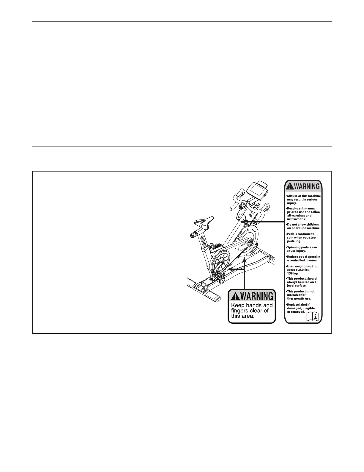
TABLE OF CONTENTS
WARNING DECAL PLACEMENT . . . . . . . . . . . . . . . . . . . . . . . . . . . . . . . . . . . . . . . . . . . . . . . . . . . . . . . . . . . . . . .2
IMPORTANT PRECAUTIONS . . . . . . . . . . . . . . . . . . . . . . . . . . . . . . . . . . . . . . . . . . . . . . . . . . . . . . . . . . . . . . . . . .3
BEFORE YOU BEGIN. . . . . . . . . . . . . . . . . . . . . . . . . . . . . . . . . . . . . . . . . . . . . . . . . . . . . . . . . . . . . . . . . . . . . . . . 4
ASSEMBLY . . . . . . . . . . . . . . . . . . . . . . . . . . . . . . . . . . . . . . . . . . . . . . . . . . . . . . . . . . . . . . . . . . . . . . . . . . . . . . . .5
HOW TO USE THE TRAINING BIKE . . . . . . . . . . . . . . . . . . . . . . . . . . . . . . . . . . . . . . . . . . . . . . . . . . . . . . . . . . . .7
COMPLIANCE INFORMATION. . . . . . . . . . . . . . . . . . . . . . . . . . . . . . . . . . . . . . . . . . . . . . . . . . . . . . . . . . . . . . . .23
PART LIST. . . . . . . . . . . . . . . . . . . . . . . . . . . . . . . . . . . . . . . . . . . . . . . . . . . . . . . . . . . . . . . . . . . . . . . . . . . . . . . . 24
EXPLODED DRAWING. . . . . . . . . . . . . . . . . . . . . . . . . . . . . . . . . . . . . . . . . . . . . . . . . . . . . . . . . . . . . . . . . . . . . .26
HOW TO CONTACT CUSTOMER CARE . . . . . . . . . . . . . . . . . . . . . . . . . . . . . . . . . . . . . . . . . . . . . . . . Back Cover
LIMITED WARRANTY. . . . . . . . . . . . . . . . . . . . . . . . . . . . . . . . . . . . . . . . . . . . . . . . . . . . . . . . . . . . . . . Back Cover
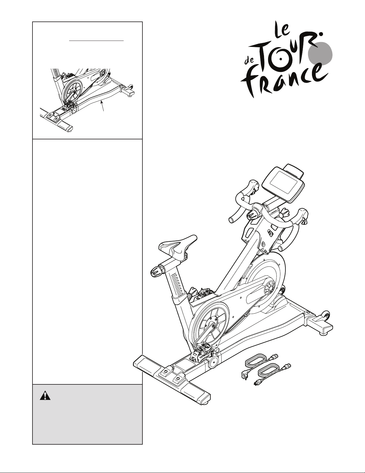
WARNING DECAL PLACEMENT
This drawing shows the location(s) of the warning
decal(s). If a decal is missing or illegible, see the
back cover of this manual and request a free
replacement decal. Apply the decal in the location shown. Warning decals in other languages
are included. Apply the warning decals on top of
the English warnings in the indicated location(s) if
desired. Note: The decal(s) may not be shown at
actual size.
FREEMOTION is a registered trademark of ICON IP, Inc.
2
Page 3

IMPORTANT PRECAUTIONS
WARNING: To reduce the risk of burns, fire, electric shock, or injury to persons, read all
important precautions and instructions in this manual and all warnings on your training bike before
using your training bike. FreeMotion Fitness assumes no responsibility for personal injury or property damage sustained by or through the use of this product.
1. It is the responsibility of the owner to ensure
that all users of the training bike are adequately informed of all precautions.
2. Before beginning any exercise program,
consult your physician. This is especially
important for persons over age 35 or persons
with pre-existing health problems.
3. Use the training bike only as described in
this manual.
4. The training bike is intended for use in a
supervised environment only.
5. Keep the training bike indoors, away from
moisture and dust. Do not put the training
bike in a garage or covered patio, or near
water.
6. Place the training bike on a level surface with
at least 2 ft. (0.6 m) of clearance around the
training bike. To protect the floor or carpet
from damage, place a mat under the training
bike.
7. Inspect and properly tighten all parts regularly. Replace any worn parts immediately.
8. Keep children under age 12 and pets away
from the training bike at all times.
9. When connecting the power cord (see page
7), plug the power cord into a grounded
circuit.
10. Do not modify the power cord or use an
adapter to connect the power cord to an
improper receptacle. Keep the power cord
away from heated surfaces. Do not use an
extension cord.
11. Do not operate the training bike if the power
cord or plug is damaged, or if the training
bike is not working properly.
12. DANGER: Always unplug the power
cord and press the power switch to the off
position when the training bike is not in
use and before cleaning the training bike.
Servicing other than the procedures in this
manual should be performed by an authorized service representative only.
13. Wear appropriate clothes while exercising;
do not wear loose clothes that could become
caught on the training bike. Always wear
athletic shoes for foot protection.
14. The training bike should not be used by persons weighing more than 350 lbs. (159 kg).
15. Be careful when mounting and dismounting
the training bike.
16. The heart rate monitor is not a medical
device. Various factors, including the user’s
movement, may affect the accuracy of heart
rate readings. The heart rate monitor is
intended only as an exercise aid in determining heart rate trends in general.
17. Always keep your back straight while using
the training bike; do not arch your back.
18. Over exercising may result in serious injury
or death. If you feel faint or if you experience
pain while exercising, stop immediately and
cool down.
SAVE THESE INSTRUCTIONS
3
Page 4
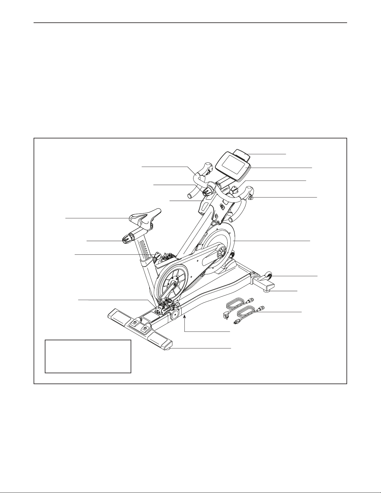
BEFORE YOU BEGIN
Congratulations for selecting the revolutionary
LE TOUR DE FRANCE® training bike. The LE TOUR
DE FRANCE training bike is unlike any ordinary exercise bike. With full adjustability, a Wi-Fi cycling console,
an incline system that simulates actual road terrain,
and an array of other innovative features, the LE TOUR
DE FRANCE training bike is designed to let you enjoy
the outdoor cycling experience indoors.
For your benefit, read this manual carefully before
you use the training bike. If you have questions after
Handlebar
Carriage Knob
Water Bottle Holder*
Saddle
reading this manual, please see the back cover of this
manual. To help us assist you, note the product model
number and serial number before contacting us. The
model number and the location of the serial number
decal are shown on the front cover of this manual.
Before reading further, please familiarize yourself with
the parts that are labeled in the drawing below.
Accessory Holder
Console
Post Knob
Shifter
Carriage Knob
Post Knob
Pedal/Strap
Length: 4 ft. 8 in. (142 cm)
Width: 2 ft. 1 in. (64 cm)
Weight: 137 lbs. (62 kg)
Flywheel
Wheel
Leveling Foot
Power Cord
Power Switch
Leveling Foot
*Water bottle is not included
4
Page 5
ASSEMBLY
• Assembly requires two persons.
• Place all parts in a cleared area and remove the
packing materials. Do not dispose of the packing
materials until you complete all assembly steps.
• If a part is not in the hardware kit, check to see if
it has been preassembled.
• To avoid damaging parts, do not use power tools.
1. Attach the Rear Stabilizer (4) to the Base (2) with
two M10 x 60mm Bolts (115), two M10 Washers
(112), and two M10 Locknuts (116).
• Assembly requires the following tools (not
included):
one 3 mm hex key
one 6 mm hex key
one Phillips screwdriver
one adjustable wrench
1
115
2
2. Attach the Front Stabilizer (3) to the Base (2)
with two M10 x 60mm Bolts (115), two M10
Washers (112), and two M10 Locknuts (116).
4
112
116
2
115
2
3
112
116
5
Page 6
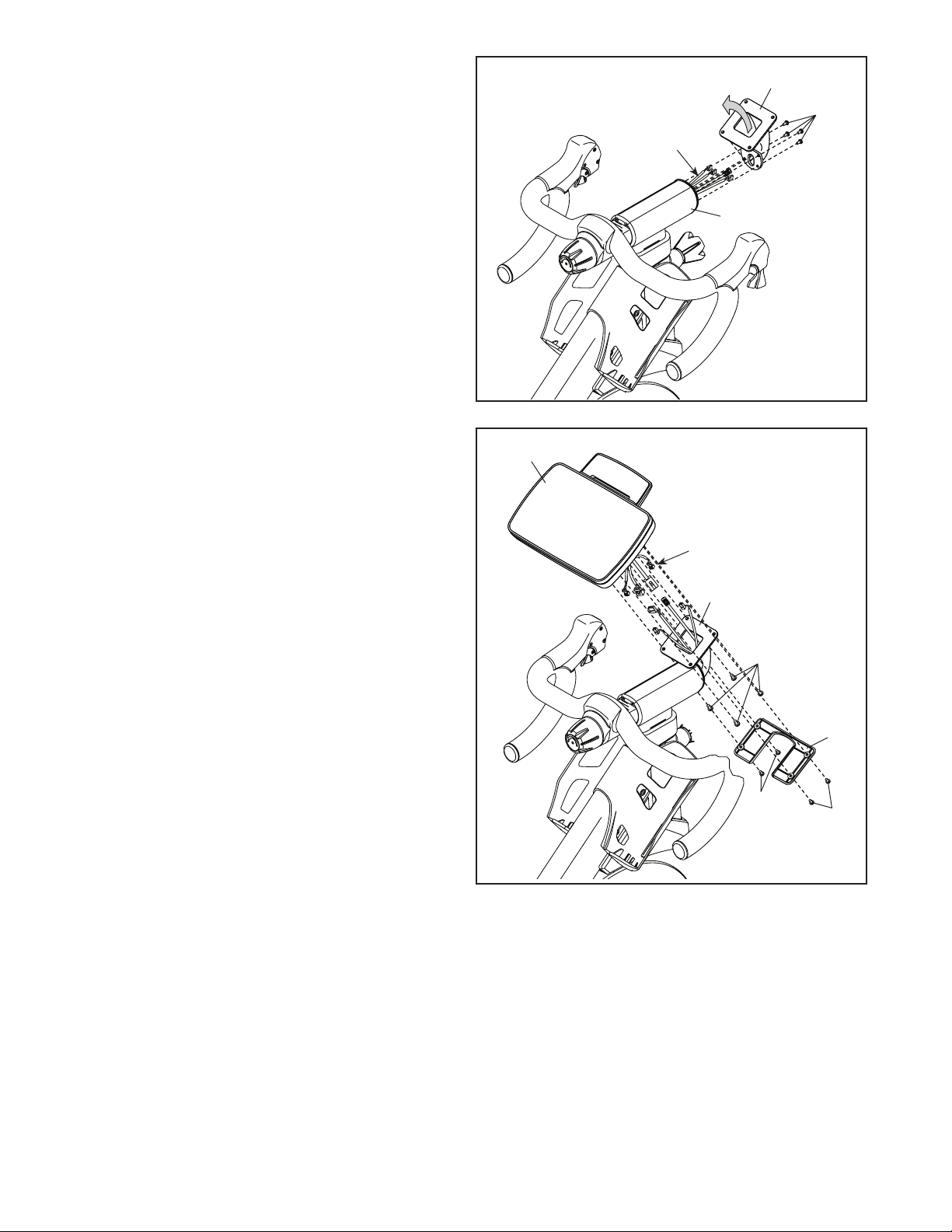
3. While a second person holds the Console Mount
(66) near the Handlebar Post (7), route the frame
wires and cable upward through the Console
Mount.
Avoid pinching the wires and cable. Attach the
Console Mount (66) to the Handlebar Post (7)
with four M4 x 6mm Screws (129).
3
Wires and
Cable
66
129
7
Avoid
pinching
the wires
and cable
4. While a second person holds the Console (10)
near the Console Mount (66), connect the console wires and cable to the matching frame wires
and cable; make sure to connect the console
wire that has a tag to the frame wire that has
a tag.
Insert the excess wires and cable into the
Console (10) and the Console Mount (66).
Tip: Avoid pinching the wires and cable.
Attach the Console (10) to the Console Mount
(66) with four M5 x 10mm Button Screws (125).
Then, attach the Console Cover (11) to the
Console Mount (66) with four M4 x 8mm Pan
Head Screws (12).
4
10
Avoid pinching the
wires and cable
Wires and Cable
66
125
11
12
12
5. After the training bike is assembled, inspect it to make sure that it is assembled correctly and that it
functions properly. Make sure that all parts are properly tightened before you use the training bike.
Note: Extra parts may be included. Place a mat beneath the training bike to protect the floor.
6
Page 7
HOW TO USE THE TRAINING BIKE
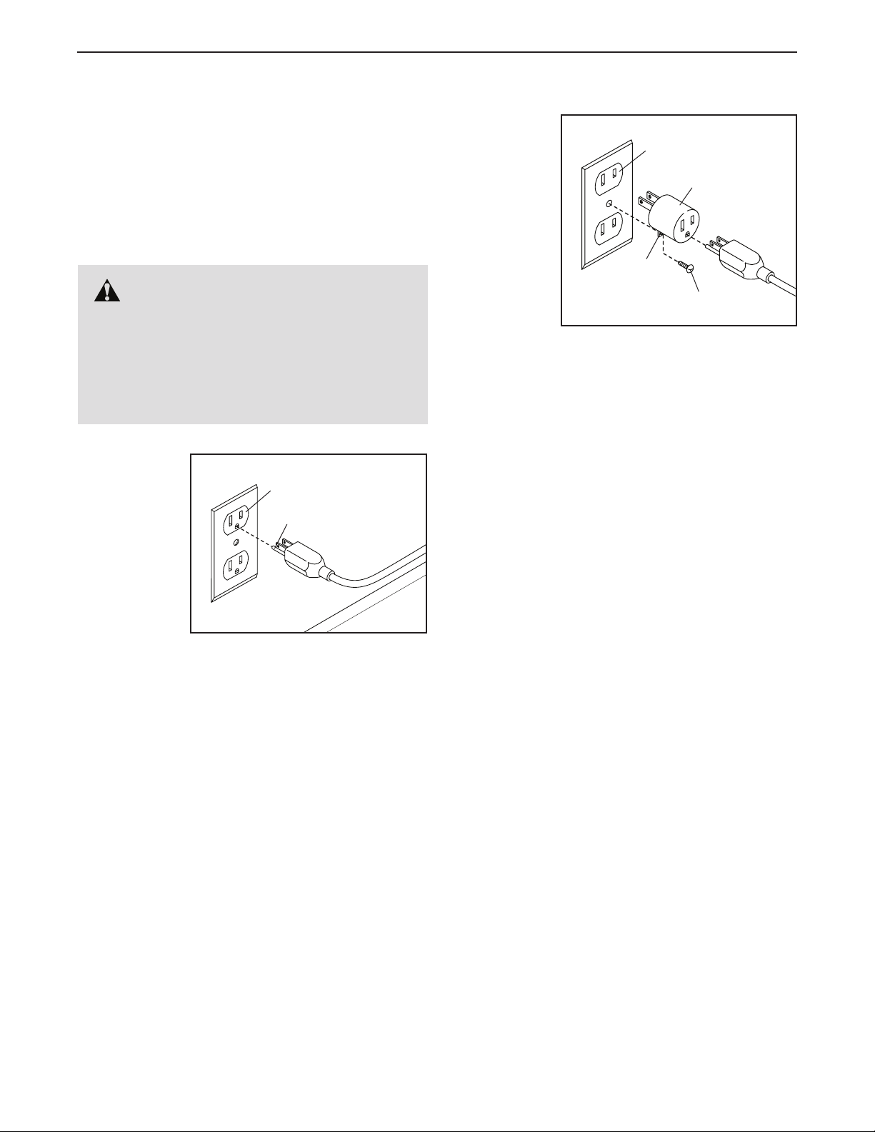
HOW TO PLUG IN THE POWER CORD IN THE
UNITED STATES OR CANADA
This product must be grounded. If it should malfunc-
tion or break down, grounding provides a path of least
resistance for electric current to reduce the risk of
electric shock. The power cord has a plug with a
grounding pin.
DANGER: Improper connection of
the power cord increases the risk of electric
shock. Do not modify the plug—if it will not fit
an outlet, have a proper outlet installed by a
qualified electrician. If you are unsure whether
the product is properly grounded, contact a
qualified electrician.
Plug the
power cord
into an
appropriate
outlet that
is properly
installed and
grounded in
accordance
with all local
codes and
ordinances.
The outlet must be on a nominal 120-volt circuit.
Grounded Outlet
Grounding Pin
A temporary
adapter may
be used to
connect the
power cord
to a 2-pole
receptacle
as shown
at the right
if a properly
grounded
outlet is not
available.
The lug or wire extending from the adapter must
be connected with a metal screw to a permanent
ground such as a properly grounded outlet box cover.
Some 2-pole receptacle outlet box covers are not
grounded. Before using an adapter, contact a qualified electrician to determine whether the outlet
box cover is grounded before using an adapter.
The temporary adapter should be used only until
a properly grounded outlet can be installed by a
qualified electrician.
WARRANTY INFORMATION
The warranty for this product does not cover damage
or equipment failure caused by electric wiring not in
compliance with electrical codes or the specifications
in this manual, or failure to provide reasonable and
necessary maintenance as outlined in this manual.
Any failure or damage caused by unauthorized service;
misuse; accident; negligence; improper assembly or
installation; debris resulting from any destruction activities in the product’s environment; rust or corrosion as a
result of the product’s location; alterations or modifications without written authorization; or failure on your
part to use, operate, and maintain the product as set
forth in this manual will void the warranty.
2-pole Receptacle
Adapter
Lug
Metal Screw
7
Page 8
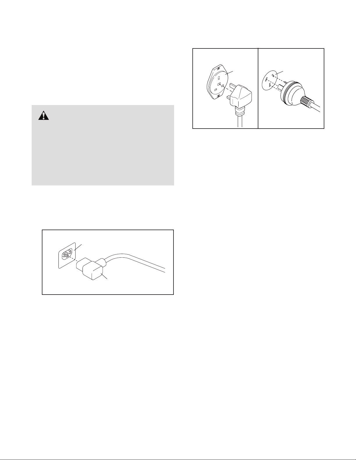
HOW TO PLUG IN THE POWER CORD IN EUROPE
OR AUSTRALIA
This product must be earthed. If it should malfunc-
tion or break down, earthing provides a path of least
resistance for electric current to reduce the risk of
electric shock. This product’s power cord has an
equipment-earthing conductor and an earthing plug.
IMPORTANT: If the power cord is damaged, it must
be replaced with a manufacturer-recommended
power cord.
DANGER: Improper connection of
the equipment-earthing conductor can result
in an increased risk of electric shock. Check
with a qualified electrician or serviceman if
you are in doubt as to whether the product
is properly earthed. Do not modify the plug
provided with the product—if it will not fit
the outlet, have a proper outlet installed by a
qualified electrician
Follow the steps below to plug in the power cord.
1. Plug the indicated end of the power cord into the
socket on the frame.
Socket on Frame
2. Plug the power cord into an appropriate outlet that
is properly installed and earthed in accordance with
all local codes and ordinances.
UK
Outlet
WARRANTY INFORMATION
The warranty for this product does not cover damage
or equipment failure caused by electric wiring not in
compliance with electrical codes or the specifications
in this manual, or failure to provide reasonable and
necessary maintenance as outlined in this manual.
Any failure or damage caused by unauthorized service;
misuse; accident; negligence; improper assembly or
installation; debris resulting from any destruction activities in the product’s environment; rust or corrosion as a
result of the product’s location; alterations or modifications without written authorization; or failure on your
part to use, operate, and maintain the product as set
forth in this manual will void the warranty.
Australia
Outlet
Power Cord
8
Page 9
FEATURES OF THE TRAINING BIKE
Measuring Watts
Each training bike is individually calibrated to measure
your power output and to allow you to monitor your
watts and RPMs directly on the console.
By monitoring your watts and RPMs, you can see how
hard you are training and make sure that you are challenging yourself and improving.
The Incline System
The training bike can incline and decline up to 20 percent to realistically simulate outdoor terrain. When you
create maps of your actual training routes on iFit.com
(see the console instructions beginning on page 11
for more information), the training bike will automatically incline and decline to match the terrain of your
training routes.
The Handlebar Shifters
The training bike allows you to shift gears just like
you do on your road bike. The right and left handlebar
shifters simulate front and rear derailleurs that you can
configure to match the gearing setup of your road bike
(see the console instructions beginning on page 11
for more information).
Pedaling Form Features
The training bike has multiple features to help you
develop correct pedaling form:
Freewheel—The training bike has a freewheel that
simulates a road bike rather than a fixed-drive spin
bike. This discourages you from letting your feet coast
through the top and bottom of your pedal stroke.
Flywheel—The flywheel on the training bike has the
correct inertia to allow you to pedal smoothly while
encouraging you to use good pedaling form.
HOW TO ADJUST THE GEOMETRY OF THE
TRAINING BIKE
The training bike can be adjusted to match the geometry of your road bike to promote correct form and to
ensure proper training of the muscles. Note: Make
adjustments in small increments, and then pedal
the training bike to test the adjustments.
How to Adjust the Angle of the Saddle
You can adjust the angle of the saddle to the position that is most comfortable. You can also adjust the
saddle forward or backward for increased comfort or to
adjust the distance to the handlebar.
To adjust the
saddle, first loosen
the hex nuts on the
saddle clamp a few
turns. Next, tilt the
saddle upward or
downward or slide
the saddle forward
or backward to the
desired position.
Then, retighten the hex nuts.
How to Adjust the Saddle Carriage
To a d ju s t t he po s ition of the saddle
carriage, loosen
the carriage knob,
move the saddle
carriage forward
or backward to the
desired position,
and then firmly
tighten the carriage
knob.
Carriage
Knob
Saddle
Clamp
Hex
Nuts
9
Page 10

How to Adjust the Saddle Post
How to Adjust the Handlebar Carriage
For effective training, the saddle should be at the
proper height. As you pedal, there should be a slight
bend in your knees when the pedals are in the lowest
position.
To a d ju s t t he sa d dl e
post, first loosen the
post knob and pull
it outward. Then,
move the saddle
post upward or
downward, release
the post knob into
an adjustment
hole in the saddle
post, and firmly
tighten the post knob. Make sure that the post knob is
engaged in an adjustment hole. IMPORTANT: Do not
adjust the saddle post beyond the stop mark on the
saddle post.
How to Adjust the Handlebar Post
To a d ju s t t he
handlebar post,
first loosen the
post knob and pull
it outward. Then,
move the handlebar post upward or
downward, release
the post knob into
an adjustment hole
in the handlebar
post, and firmly tighten the post knob. Make sure that
the post knob is engaged in an adjustment hole.
IMPORTANT: Do not adjust the handlebar post
beyond the stop mark on the handlebar post.
Post
Knob
Post
Knob
To adjust the
position of the
handlebar, loosen
the carriage knob,
move the handlebar
forward or backward to the desired
position, and then
firmly tighten the
carriage knob.
HOW TO LEVEL THE TRAINING BIKE
If the training bike rocks slightly on your floor during
use, turn one or both of the leveling feet on the front or
rear stabilizer (see the drawing on page 4) until the
rocking motion is eliminated.
HOW TO USE THE PEDALS
To u s e t he to e c a ge si d e o f t he pe da ls ( s ee th e d r aw ing on page 4), insert your shoes into the toe cages
and pull the ends of the toe straps. To adjust the toe
straps, press and hold the tabs on the buckles, adjust
the toe straps to the desired position, and then release
the tabs.
To u s e t he cl i p- i n s id e o f t h e p ed al s, y o u m us t w e ar
cycling shoes. To clip into the pedals, press the cleats
on your cycling shoes firmly into the slots in the pedals
until they snap into place. To unclip from the pedals,
twist your cycling shoes outward from the pedals.
HOW TO MAINTAIN THE TRAINING BIKE
Inspect and tighten all parts of the training bike regularly. Replace any worn parts immediately.
To c l ea n t h e t ra i ni n g b ik e , u se a da mp c l ot h a n d a
small amount of mild detergent.
Carriage
Knob
For maximum performance and safety, replace the
pedals every year. To purchase pedals, see the back
cover of this manual.
IMPORTANT: To avoid damage to the training bike
and to prevent injury to the user, use only manufacturer-supplied pedals. Other pedals may not be
designed for use in fitness clubs or indoor cycling
studios and may be dangerous.
10
Page 11

CONSOLE DIAGRAM
MAKE YOUR FITNESS GOALS A REALITY WITH
IFIT.COM
With your new iFit-compatible fitness equipment, you
can use an array of features on iFit.com to make your
fitness goals a reality:
Exercise anywhere in the world with
customizable Google Maps.
Download training workouts designed to
help you reach your personal goals.
Measure your progress by competing
against other users in the iFit community.
Upload your workout results to the iFit cloud
and track your accomplishments.
Set calorie, time, or distance goals for your
workouts.
Watch high-definition videos with simulated
workouts.
Choose and download sets of weight-loss
workouts
Go to iFit.com to learn more.
11
Page 12

FEATURES OF THE CONSOLE
HOW TO TURN ON THE POWER
The advanced console offers an array of features
designed to make your workouts more effective and
enjoyable.
When you use the manual mode of the console, you
can change the incline (resistance) of the training bike
and change gears with the touch of a button.
While you exercise, the console will display continuous exercise feedback, including watts and pedaling
cadence feedback.
During your workout, you can do intervals at any time
to measure your performance over short periods of
time. The console will record and display your results
for each interval.
You ca n als o me as ur e y ou r he ar t r at e us in g a n op ti ona l
heart rate monitor.
In addition, the console offers twenty-four Le Tour de
France workouts. Each workout automatically changes
the incline (resistance) of the training bike to match the
real terrain of the Le Tour de France bicycle race and
allows you to change gears to maintain your desired
pedaling cadence.
The console also features new iFit technology that
enables the console to communicate with your wireless
network. With iFit technology, you can download personalized workouts, create your own workouts, track
your workout results, and access many other features.
See www.iFit.com for complete information.
You ca n ev en c onn ec t yo ur M P3 p la yer o r CD p la ye r
to the console sound system and listen to your favorite
music or audio books while you exercise.
IMPORTANT: If the training bike has been exposed
to cold temperatures, allow it to warm to room temperature before you turn on the power. If you do
not do this, you may damage the console displays
or other electrical components.
Plug in the power cord (see
HOW TO PLUG IN THE
POWER CORD on page
7). Next, locate the
power switch on the frame
near the power cord. Press
the power switch to the
reset position.
The display will then turn on and the console will be
ready for use.
Note: When you turn on the power for the first time,
the incline system may calibrate automatically.
The training bike will move upward and downward as
it calibrates. When the training bike stops moving, the
incline system is calibrated.
IMPORTANT: If the incline system does not calibrate automatically, see step 4 on page 21 and
manually calibrate the incline system.
IMPORTANT: The console features a display demo
mode, designed to be used if the training bike is
displayed in a store. If the demo mode is turned on,
the console will not turn off and the display will not
be reset when you fi nish exercising. To turn off the
demo mode, see step 8 on page 19.
Reset
Position
To turn on the power, see this page. To l e a r n h o w to
use the touch screen, see page 13. To set up the
console, see page 13.
12
Page 13

HOW TO USE THE TOUCH SCREEN
The console features a tablet with a full-color touch
screen. The following information will help you become
familiar with the tablet’s advanced technology:
• The console functions similarly to other tablets. You
can slide or flick your finger against the screen to
move certain images on the screen, such as the
displays in a workout. However, you cannot zoom in
and out by sliding your fingers on the screen.
the console must be connected to a wireless
network. See HOW TO USE THE WIRELESS
NETWORK MODE on page 22 to connect the
console to your wireless network.
2. Check for firmware updates.
First, see step 1 on page 19 and step 2 on page
21 and select the maintenance mode. Then,
see step 3 on page 21 and check for firmware
updates.
• To type information into a text box, first touch the text
box to view the keyboard. To use numbers or other
characters on the keyboard, touch the ?123 button. To view more characters, touch the Alt button.
To uc h t h e Al t b u tt o n a ga i n t o r et u rn t o th e n u mb e r
keyboard. To return to the letter keyboard, touch the
ABC button. To use a capital character, touch the
button with an upward-facing arrow. To use multiple
capital characters, touch the arrow button again. To
return to the lowercase keyboard, touch the arrow
button a third time. To clear the last character, touch
the button with a backward-facing arrow and an X.
• Use these buttons
on the console to
navigate the tablet.
Press the home button to return to the
main menu. Press the
center button to access the settings menu (see page
19). Press the back button to return to the previous screen.
• If it is difficult for you to touch the correct buttons
on the screen, the screen may not be properly
calibrated. To calibrate the screen, see step 5 on
page 21.
HOW TO SET UP THE CONSOLE
Before using the training bike for the first time, follow
the steps below to set up the console.
1. Connect to a wireless network.
Note: To access the Internet, download iFit work-
outs, and use some other features of the console,
3. Calibrate the incline system.
First, see step 1 on page 19 and step 2 on page
21 and select the maintenance mode. Then,
see step 4 on page 21 and calibrate the incline
system of the training bike.
4. Create an iFit account.
On your computer, smartphone, tablet, or other
Internet-capable device, open an Internet browser
and go to www.iFit.com. Follow the prompts on the
website to sign up for your iFit membership. If you
have an activation code, select the code activation
option.
The console is now ready for you to begin training. The
following pages explain the various workouts and other
features that the console offers.
To use the manual mode, see page 14. To use a
Le Tour de France workout, see page 15. To use
a set-a-goal workout, see page 16. To use an iFit
workout, see page 17.
To use the sound system, see page 18. To use
the Internet browser, see page 18. To use the
equipment settings mode, see page 19. To use
the maintenance mode, see page 21. To use the
wireless network mode, see page 22.
Note: If there is a sheet of plastic on the display,
remove the plastic.
The console can display speed and distance in either
miles or kilometers. To fi nd which unit of measurement
is selected, see step 16 on page 20.
13
Page 14

HOW TO USE THE MANUAL MODE
1. Touch the screen or begin pedaling to activate
the console.
See HOW TO TURN ON THE POWER on
page 12.
2. Select the main menu.
When you turn on the console, the main menu will
appear on the screen after the console boots up.
Touch the home button at the bottom of the screen
to return to the main menu at any time.
Touch the Start button to start a manual workout.
3. Change the incline (resistance) of the training
bike as desired.
As you pedal, change the incline (resistance) of the
training bike by pressing the Grade increase and
decrease buttons on the console.
You ca n al so c han ge t he i nc li ne o f t he t ra in in g
bike by pressing the shifter buttons. To increase
the incline, press the front and rear buttons on the
right shifter simultaneously; to decrease the incline,
press the front and rear buttons on the left shifter
simultaneously.
Note: After you press a button, it will take a
moment for the training bike to reach the selected
incline level. You will hear the incline motor
while the incline is changing. This is normal.
Change gears by pressing the buttons on the
shifters. Note: After you press a button, it will take
a moment for the training bike to change to the
selected gear. To avoid damaging th e s h i f t -
ers, do not pull on the shifters or squeeze the
shifters.
Press the buttons on the left shifter to change the
front gear; press the buttons on the right shifter to
change the rear gear.
On the left shifter, press the front button to increase
the resistance; press the rear button to decrease
the resistance.
On the right shifter, press the front button to
increase the resistance; press the rear button to
decrease the resistance.
The numbers of the currently selected front and
rear gears will appear in the display on the screen.
5. Follow your progress.
The console offers several display modes. The
display mode that you select will determine which
workout information is shown.
To s e le c t t he de s ir e d d is p la y m o de , si mp l y f li c k o r
slide the screen. You can also view additional workout information by touching the red boxes on the
screen.
If desired, adjust the volume level by pressing the
Volume increase and decrease buttons on the
console.
CAUTION: The training bike can move through
a broad range of incline levels. Hold the handlebars and be prepared for the training bike to
move when you change the incline.
4. Change gears as desired.
You can set up the training bike to simulate
your road bike. To select the gearing option(s)
for the training bike, see step 7 on page 19.
Note: The training bike simulates gears; there are
no actual gears.
To pause the workout, stop pedaling or touch either
the back button or the home button at the bottom
of the screen. To continue the workout, touch the
Resume button. To end the workout session, touch
the End Workout button.
When you touch the End Workout button, a work-
out summary will appear on the screen. After you
view the workout summary, touch the Finish button
to return to the main menu. You may also be able
to either save or publish your results using one of
the options on the screen.
14
Page 15

6. Do intervals if desired.
2. Select the main menu.
During a workout, you can use the interval screen
to measure your performance for short periods of
time. To select the interval screen, simply flick or
slide the screen.
To b e gi n a n i n te r va l , t ou c h t he St ar t bu t to n . To en d
the current interval, touch the Lap button. You can
add as many intervals as desired to your workout.
The console will record data for each interval that
you can view at any time during your workout. The
interval screen will show a list of the recorded intervals. Scroll the screen to view data for the desired
interval.
7. Wear a heart rate monitor and measure your
heart rate if desired.
You ca n we ar a n o pt io na l he ar t ra te mo ni to r to
measure your heart rate. Note: The console is
compatible with ANT + and POLAR heart rate
monitors.
When your heart beat is detected, your heart rate
will be shown in the display on the screen.
8. When you are fi nished exercising, unplug the
power cord.
See step 2 on page 14.
3. Select a Le Tour de France workout.
To select a Le Tour de France workout, first touch
the cyclist button at the bottom of the screen. The
workouts menu will appear on the screen.
Next, select the Tour de France button. Then,
select the desired workout. Note: It may be necessary to scroll the screen to view all the workout
options.
The screen will show the name, the estimated
duration, and the distance of the workout. The
screen will also show the approximate number of
calories you will burn during the workout and a map
of the workout. Note: You may be able to select
other variables for the workout on this screen.
4. Start the workout.
Touch the Start Workout button to start the workout.
The workout may have a warm-up segment. To
skip the warm-up segment, touch the Skip button.
To s e le c t w ar m -u p s e gm e nt op t io n s fo r th e t r ai n in g
bike, see step 17 on page 20.
When you are fi nished exercising, press the power
switch to the off position and unplug the power
cord. IMPORTANT: If you do not do this, the
electrical components of the training bike may
wear prematurely.
HOW TO USE A LE TOUR DE FRANCE WORKOUT
1. Touch the screen or begin pedaling to activate
the console.
See HOW TO TURN ON THE POWER on
page 12.
Each workout is divided into several segments.
One incline level (resistance) is programmed for
each segment. Note: The same incline level may
be programmed for consecutive segments.
During the workout, the screen will show a map of
the route and a marker indicating your progress.
To uc h t h e b ut t on s o n t h e s cr e en to s el ec t t h e
desired map options.
The profiles display will show your progress. To
view the profiles display, flick or slide the screen.
15
Page 16

At the end of the first segment of the workout, the
incline will automatically adjust to the incline level
for the next segment.
When the incline changes, the resistance of the
pedals will also change. To maintain a steady
pedaling cadence, change gears by pressing the
buttons on the shifters.
Note: You can manually override the incline set-
tings by pressing the Grade buttons. To return to
the programmed incline settings of the workout, touch the Follow Workout button.
HOW TO USE A SET-A-GOAL WORKOUT
1. Touch the screen or begin pedaling to activate
the console.
See HOW TO TURN ON THE POWER on
page 12.
2. Select the main menu.
See step 2 on page 14.
3. Select a set-a-goal workout.
Note: The calorie goal is an estimate of the
number of calories that you will burn during the
workout. The actual number of calories that you
burn will depend on various factors such as
your weight. In addition, your pedaling cadence
will affect the number of calories you burn.
To p a us e t h e w or k ou t , s to p p e da l in g or t o uc h e i th e r
the back button or the home button at the bottom
of the screen. To continue the workout, touch the
Resume button. To end the workout, touch the End
Workout button.
The workout will continue in this way until the last
segment ends. A workout summary will appear on
the screen. After you view the workout summary,
touch the Finish button to return to the main menu.
You ma y al so b e a bl e to e it he r sa ve or p ub li sh y ou r
results using one of the options on the screen.
5. Follow your progress.
See step 5 on page 14.
6. Do intervals if desired.
See step 6 on page 15.
To s e le c t a s e t- a -g o al wo r ko u t, to uc h th e S e t A
Goal button on the screen.
To set a customized goal for your workout, touch
the button for the desired goal. Then, touch the
increase and decrease buttons on the screen to
enter your goal and to select other variables for the
workout. The screen will show the duration and distance of the workout, and the approximate number
of calories you will burn during the workout.
4. Start the workout.
The workout may have a warm-up segment. To
skip the warm-up segment, touch the Skip button.
To s e le c t w ar m -u p s e gm e nt op t io n s fo r th e t r ai n in g
bike, see step 17 on page 20.
Touch the Start button to start the workout.
The workout will function in the same way as the
manual mode (see page 14).
Note: You can manually override the incline set-
tings by pressing the Grade buttons. To return to
the programmed incline settings of the workout, touch the Follow Workout button.
7. Wear a heart rate monitor and measure your
heart rate if desired.
See step 7 on page 15.
8. When you are fi nished exercising, unplug the
power cord.
See step 8 on page 15.
The workout will continue until you reach the goal
that you set. A workout summary will appear on
the screen. After you view the workout summary,
touch the Finish button to return to the main menu.
You ma y al so b e a bl e to e it he r sa ve or p ub li sh y ou r
results using one of the options on the screen.
16
Page 17

Note: The calorie goal is an estimate of the
number of calories that you will burn during
the workout. The actual number of calories that
you burn will depend on various factors, such
as your weight. In addition, if you manually
change gears or the incline during the workout, the number of calories you burn will be
affected.
5. Follow your progress.
See step 5 on page 14.
6. Do intervals if desired.
See step 6 on page 15.
7. Wear a heart rate monitor and measure your
heart rate if desired.
See step 7 on page 15.
8. When you are fi nished exercising, unplug the
power cord.
button. Touch the Cancel button to exit the login
screen. Note: Usernames and passwords are
case-sensitive.
To s w it c h u se r s w it h in yo u r i Fi t a cc ou nt , t o uc h t h e
user button at the bottom of the screen. If more
than one user is associated with the account, a list
of users will appear. Touch the name of the desired
user.
4. Select an iFit workout.
To d o wn l oa d a n i F it wo r ko u t i n y ou r sc he d ul e ,
touch the Map, Train, Video, or Lose Wt. button
to download the next workout of that type in your
schedule. Note: You may be able to access demo
workouts through these options, even if you do not
log in to an iFit account.
To c o mp e te in a r ac e t h at yo u h a ve p re vi o us l y
scheduled, touch the Compete button. To view your
Workout History, touch the Track button. To use a
set-a-goal workout, touch the Set A Goal button
(see page 16).
See step 8 on page 15.
HOW TO USE AN IFIT WORKOUT
Note: To use an iFit workout, you must have access
to a wireless network (see HOW TO USE THE
WIRELESS NETWORK MODE on page 22). An iFit
account is also required.
1. Touch the screen or begin pedaling to activate
the console.
See HOW TO TURN ON THE POWER on
page 12.
2. Select the main menu.
See step 2 on page 14.
3. Log in to your iFit account.
If you have not already done so, touch the
Login button to log in to your iFit account. The
screen will ask for your iFit.com username and
password. Enter them and touch the Login
Before some workouts will download, you must add
them to your schedule on iFit.com.
For more information about the iFit workouts,
please see www.iFit.com.
When you select an iFit workout, the screen will
show the name, the estimated duration, and the
distance of the workout. The screen will also show
the approximate number of calories you will burn
during the workout. If you select a competition
workout, the display will count down to the beginning of the race.
5. Start the workout.
See step 4 on page 15.
An audio coach may guide you through some work-
outs (see HOW TO USE THE SOUND SYSTEM on
page 18).
Note: You can manually override the incline set-
tings by pressing the Grade buttons. To return to
the programmed incline settings of the workout, touch the Follow Workout button.
17
Page 18

6. Follow your progress.
HOW TO USE THE INTERNET BROWSER
See step 5 on page 14. The screen may also
show a map of the trail you are walking or running. Touch the buttons on the screen to select the
desired map options.
During a competition workout, the screen will show
the speeds of the racers and the distances they
have traveled. The screen will also show the numbers of seconds that the other racers are ahead of
you or behind you.
7. Do intervals if desired.
See step 6 on page 15.
8. Wear a heart rate monitor and measure your
heart rate if desired.
See step 7 on page 15.
9. When you are fi nished exercising, unplug the
power cord.
See step 8 on page 15.
Note: To use the Internet browser, you must have
access to a wireless network including a wireless
router (802.11b/g/n) with SSID broadcast enabled (hidden networks are not supported).
To o p en th e I n te r ne t b r ow s er , t ou c h th e gl o be bu t to n a t
the bottom of the screen. Then, select a website.
To n a vi g at e t h e I nt e rn e t b ro w se r, to uc h th e B a ck ,
Refresh, and Forward buttons on the screen. To exit
the Internet browser, touch the Return button on the
screen.
To u s e t he ke y bo a rd , s e e H OW T O U SE T HE T OU CH
SCREEN on page 13.
To e n te r a di ff er en t w e b a dd r es s i n t h e U RL b a r, f i rs t ,
slide your finger down the screen to view the URL bar,
if necessary. Then, touch the URL bar, use the keyboard to enter the address, and touch the Go button.
Note: While you are using the Internet browser, the
incline, gear, and volume buttons will still function, but
the workout buttons will not function.
For more information about iFit, go to
www.iFit.com.
HOW TO USE THE SOUND SYSTEM
To l i st e n t o t he co n so l e a ud i o w it h yo ur pe r so n al he a dphones or ear buds, plug your headphones into the
audio jack on the console.
Note: If you have questions after following these
instructions, go to www.support.iFit.com for
assistance.
18
Page 19

HOW TO USE THE EQUIPMENT SETTINGS MODE
5. Enable or disable the Internet browser.
Note: Some of the features described may not be
enabled. Occasionally, a firmware update may cause
your console to function slightly differently.
1. Select the settings main menu.
Turn on the console and select the main menu (see
steps 1 and 2 on page 14).
Then, draw a
square clockwise
on the screen to
access the settings main menu.
Note: You can
also press the
center button on
the console to
access the settings main menu.
2. Select the equipment settings mode.
In the settings main menu, touch the Equipment
Settings button.
Note: It may be necessary to scroll the screen to
view all the menu options.
To e n ab l e o r d is a bl e t h e I nt e rn e t br ow se r, fi r st
touch the Browser button. Next, touch the Enable
checkbox or the Disable checkbox. Then, touch the
back button on the screen.
6. Select a time for the cadence timeout.
The console features a cadence timeout feature; if
no buttons are touched or pressed and the pedals
do not move for a set amount of time, the console
will prompt you to resume or end the workout.
To s e le c t t he am o un t o f t i me th e c on so le wi l l w ai t
before it prompts you to resume or end the workout, touch the Cadence Timeout button and select
the desired time. Then, touch the back button on
the screen.
7. Select the gearing options.
The gearing on the training bike can be set up
to simulate a variety of gearing options used on
road bikes.
To select a front gearing option, fi rst touch
the Choose Front Gears button. Next, select the
desired front gearing option for the training bike.
Then, touch the back button on the screen.
3. Enable or disable the auto relogin feature.
Enable this feature to have the console automati-
cally log in to your iFit account when you turn on
the power. Note: This feature is recommended for
private owners of the training bike only.
To e n ab l e o r d is a bl e t h e a ut o r e lo gi n fe a tu r e, fi r st
touch the Auto Relogin button. Next, touch the
Enable checkbox or the Disable checkbox. Then,
touch the back button on the screen.
4. Enable or disable automatic console updates.
To e n ab l e o r d is a bl e a u to m at i c c on so le u p da t es ,
first touch the Auto Update button. Next, touch the
Enable checkbox or the Disable checkbox. Then,
touch the back button on the screen.
Note: To select a time for automatic console
updates, see step 15.
To select a rear gearing option, fi rst touch the
Choose Rear Gears button. Next, select the
desired rear gearing option for the training bike.
Then, touch the back button on the screen.
IMPORTANT: For detailed information about
gearing options, consult a road cycling book or
other road cycling resource.
8. Turn on or turn off the display demo mode.
The console features a display demo mode,
designed to be used if the training bike is displayed
in a store. While the demo mode is turned on, the
screen will show a demo presentation.
To turn on or turn off the display demo mode, first
touch the Demo Mode button. Next, touch the On
checkbox or the Off checkbox. Then, touch the
back button on the screen.
19
Page 20

9. Select a language.
15. Select an update time.
To s e le c t a l a ng u ag e , t ou c h t he La ng ua ge bu t to n
and select the desired language. Then, follow the
prompts on the screen. Note: This feature may not
be enabled.
10. Enable or disable a passcode.
The console features a child safety passcode,
designed to prevent unauthorized users from using
the training bike.
To e n ab l e o r d is a bl e a pa s sc o de , t ou ch t h e
Passcode button. To enable a passcode, touch the
Enable checkbox. Then, enter a 4-digit passcode
of your choice. Touch the Save button to use this
passcode. Touch the Cancel button to return to the
equipment settings mode and not use a passcode.
To d i sa b le th e p a ss c od e , t ou c h t he D is ab l e c he c kbox. Then, touch the back button on the screen.
Note: If a passcode is enabled, the console will
regularly ask for you to enter the passcode. The
console will remain locked until the correct passcode is entered. IMPORTANT: If you forget your
passcode, enter the following master passcode
to unlock the console: 1985.
13. Enable or disable street view.
During some workouts, the screen may show a
map. To enable or disable the street view feature of
the maps, first touch the Street View button. Next,
touch the Enable checkbox or the Disable checkbox. Then, touch the back button on the screen.
To s e le c t a t i me fo r a u to m at i c c on so le u p da t es ,
touch the Update Time button and select the
desired time. Then, touch the back button on the
screen.
When you select an update time, you must also
enable automatic console updates (see step 4).
IMPORTANT: You must still unplug the power
cord after using your training bike. Set the
update time for a time when you normally
use your training bike and will be available to
unplug the power cord after an update.
16. Select the unit of measurement.
To uc h t h e U S/ M et r ic bu t to n t o v i ew t he s e le c te d
unit of measurement. Next, touch the checkbox for
the desired unit of measurement. Then, touch the
back button on the screen.
17. Select a warm-up segment option.
When you select a workout, there may be a warm-
up segment before the workout begins. To select a
time for the for the warm-up segment or to disable
the warm-up segment, touch the Warm Up Time
button and select the desired option. Then, touch
the back button on the screen.
18. Exit the equipment settings mode.
To e x it th e e q ui p me n t s et t in g s m od e, t ou c h t he
back button on the screen.
14. Select a time zone.
To s e le c t a t i me zo n e, to u ch th e T im ez on e b ut t on
and select the desired time zone. Then, touch the
back button on the screen.
20
Page 21

HOW TO USE THE MAINTENANCE MODE
Note: Some of the features described may not be
enabled. Occasionally, a firmware update may cause
your console to function slightly differently.
1. Select the settings main menu.
See step 1 on page 19.
2. Select the maintenance mode.
The training bike will automatically rise to the maxi-
mum incline level, lower to the minimum incline
level, and then return to the starting position. This
will calibrate the incline system.
IMPORTANT: Keep pets, feet, and other objects
away from the training bike while the incline
system is calibrating.
When the incline system is calibrated, touch the
back button on the screen.
In the settings main menu, touch the Maintenance
button to enter the maintenance mode.
The maintenance mode main screen will show
information about the console and the wireless
network.
3. Update the console firmware.
For the best results, regularly check for firmware
updates.
To uc h t h e F ir m wa r e U pd a te bu t to n t o ch ec k f o r
firmware updates using your wireless network. The
update will begin automatically. Note: If there are
no firmware updates available, touch the back button on the screen.
IMPORTANT: To avoid damaging the training
bike, do not turn off the power while the firmware is being updated.
The screen will show the progress of the update.
When the update is complete, the training bike will
turn off and then turn back on. If it does not, press
the power switch into the off position. Wait for several seconds, and then press the power switch into
the reset position. Note: It may take a few minutes
for the console to be ready for use.
Note: Occasionally, a firmware update may cause
your console to function slightly differently. These
updates are always designed to improve your training experience.
5. Calibrate the screen.
If the screen is not properly calibrated, it will be
difficult for you to touch the correct buttons on the
screen. To calibrate the screen, touch the Calibrate
Screen button. A small target will appear on the
screen.
Using a pencil eraser or other small object, touch
the center of the target. Then, touch the rest of the
targets. After several seconds, the console will exit
the screen calibration mode. Note: This feature
may not be enabled.
6. View machine information.
To uc h t h e M ac h in e I n fo bu t to n t o v ie w in f or m at i on
about your training bike. After you view the information, touch the back button on the screen.
7. Find keycodes.
This option is intended to be used by service
technicians to identify whether a certain button is
working correctly.
8. Enter a custom IP address.
If your network does not automatically generate IP
addresses, touch the Custom IP button to enter a
custom IP address. Note: This feature may not be
enabled.
9. Exit the maintenance mode.
4. Calibrate the incline system of the training bike.
To uc h t h e C al i br a te In c li n e b ut t on . Th e n, to u ch th e
Begin button to calibrate the incline system.
To e x it th e m a in t en a nc e m o de , t o uc h th e b ac k
button on the screen.
21
Page 22

HOW TO USE THE WIRELESS NETWORK MODE
The console features a wireless network mode that
allows you to set up a wireless network connection.
When a list of networks appears, touch the desired
network. Note: You will need to know your network
name (SSID). If your network has a password, you
will also need to know the password.
Note: You must have your own wireless network and
an 802.11b/g/n router with SSID broadcast enabled
(hidden networks are not supported).
1. Select the settings main menu.
See step 1 on page 19.
2. Select the wireless network mode.
In the settings main menu, touch the Network
Setup button to enter the wireless network mode.
Note: You can also touch the wireless symbol but-
ton at the bottom of the screen to enter the wireless
network mode.
3. Enable Wi-Fi.
Make sure that the Wi-Fi checkbox is marked with
a green checkmark. If it is not, touch the Wi-Fi
menu option once and wait for a few seconds. The
console will search for available wireless networks.
4. Set up and manage a wireless network
connection.
An information box will ask if you want to connect
to the wireless network. Touch the Connect button
to connect to the network or touch the Cancel button to return to the list of networks. If the network
has a password, touch the password entry box. A
keyboard will appear on the screen. To view the
password as you type it, touch the Show Password
checkbox.
To use the keyboard, see HOW TO USE THE
TOUCH SCREEN on page 13.
The Wi-Fi menu option will inform you when the
console is connected to your wireless network.
To d i sc o nn e ct fr o m a w i re l es s n e tw or k, s e le c t t he
wireless network and then touch the Forget button.
If you are having problems connecting to an
encrypted network, make sure that your password
is correct. Note: Passwords are case-sensitive.
Note: The iFit mode supports unsecured and
secured (WEP, WPA, and WPA2) encryption. A
broadband connection is recommended; performance depends on connection speed.
When Wi-Fi is enabled, the screen will show a list
of available networks. Note: It may take several
seconds for the list of wireless networks to appear.
Make sure that the checkbox on the Network
notification menu option is marked with a green
checkmark to have the console notify you when a
wireless network is within range and available.
Note: If you have questions after following
these instructions, go to www.support.iFit.com
for assistance.
5. Exit the wireless network mode.
To e x it th e w i re l es s n e tw o rk mo d e, t ou ch th e b a ck
button on the screen.
22
Page 23

COMPLIANCE INFORMATION
UNITED STATES
This equipment has been tested and found to comply
with the limits for a Class B digital device, pursuant to
part 15 of the FCC Rules. These limits are designed
to provide reasonable protection against harmful
interference in a residential installation. This equipment generates, uses, and can radiate radio frequency
energy and, if not installed and used in accordance
with the instructions, may cause harmful interference to
radio communications. However, there is no guarantee
that interference will not occur in a particular installation. If this equipment does cause harmful interference
to radio or television reception, which can be determined by turning the equipment off and on, try to
correct the interference by one or more of the following
measures:
• Reorient or relocate the receiving antenna.
• Increase the separation between the equipment and
the receiver.
• Connect the equipment into an outlet on a circuit dif-
ferent from that to which the receiver is connected.
• Consult the dealer or an experienced radio/TV tech-
nician for help.
CANADA
This device complies with RSS-210 of the Industry
Canada (IC) Rules. Operation is subject to the following two conditions: (1) This device may not cause
harmful interference, and (2) this device must accept
any interference received, including interference that
may cause undesired operation. CAUTION: The
device for operation in the band 2.412–2.462 GHz is
only for indoor use.
Radiation Exposure Statement: This equipment complies with IC radiation exposure limits set forth for an
uncontrolled environment. This equipment should be
installed and operated with minimum distance 20 cm
between the radiator and your body. Information can
be obtained at: http://www.hc-sc.gc.ca/ewh-semt/pubs/
radiation/radio_guide-lignes_direct-eng.php
ICES-003/NMB-003 Statement: This device complies
with Canadian ICES-003 Class B.
Note: The console contains IC ID: 3673A-339918.
FCC CAUTION: To assure continued compliance,
use only shielded interface cables when connecting to computer or peripheral devices. Changes or
modifications not expressly approved by the party
responsible for compliance could void the user’s
authority to operate this equipment.
IMPORTANT: To satisfy exposure compliance
requirements, the antenna and transmitter in the
console must be at least 8 in. (20 cm) from all
persons and must not be near or connected to any
other antenna or transmitter.
Note: The console contains FCC ID: OMC339918.
23
Page 24

PART LIST
K e y N o . Q t y . D e s c r i p t i o n K e y N o . Q t y . D e s c r i p t i o n
Model No. FMEX81912.0 R0114B
1 1 Frame
2 1 Base
3 1 Front Stabilizer
4 1 Rear Stabilizer
5 2 Stabilizer Guard
6 2 Pivot Clamp
7 1 Handlebar Post
8 1 Handlebar Selector
9 1 M5 x 16mm Screw
10 1 Console
11 1 Console Cover
12 4 M4 x 8mm Pan Head Screw
13 1 Saddle Post
14 1 Saddle Selector
15 3 M5 x 16mm Flat Head Screw
16 1 Pulley/Crank
17 6 M4 x 12mm Screw
18 5 M8 x 12mm Screw
19 1 Bottom Bracket
20 1 Pivot Bracket
21 1 Left Crank
22 1 Flywheel Assembly
23 1 Small Pulley
24 1 Flywheel Retaining Ring
25 1 Carbon Drive Belt
26 2 Adjustment Assembly
27 2 3/8" Axle Nut
28 1 Fender
29 1 Frame Guard
30 1 Left Belt Guard
31 2 Guard Cap
32 1 Right Belt Guard
33 1 Magnet/Cover
34 1 Front Base Shield
35 1 Rear Base Shield
36 2 Pivot Cover
37 1 Lift Cover
38 1 Head Cover
39 2 Crank Screw
40 1 Accessory Tray
41 2 Knob Pin Washer
42 1 Saddle Wear Strip
43 1 Saddle Carriage Cover
44 2 Saddle Post Cover
45 1 Rear Saddle Post Sleeve
46 1 Front Saddle Post Sleeve
47 1 Rear Handlebar Post Sleeve
48 1 Front Handlebar Sleeve
49 2 Wheel Assembly
50 2 Cap A
51 2 Cap B
52 2 Lower Wedge
53 2 Upper Wedge
54 1 Saddle
55 2 Pedal Washer
56 1 Pedal Set
57 27 M4 Small Washer
58 1 Lift Assembly
59 1 Lift Boot
60 1 Left Pivot Shield
61 1 Right Pivot Shield
62 1 Lift Shroud
63 1 Lift Shroud Ring
64 1 Right Pivot Shield Cover
65 1 Left Pivot Shield Cover
66 1 Console Mount
67 1 Saddle Carriage
68 1 Saddle Adjustment Bracket
69 2 Bracket Bushing
70 1 Saddle Adjustment Shaft
71 2 Knob Pin
72 2 Post Knob
73 2 M5 x 20mm Screw
74 2 Knob Cap
75 1 Resistance Motor
76 1 Motor Bracket
77 1 Limit Switch
78 1 Brake Pivot
79 2 Limit Switch Nut
80 1 Brake Magnet
81 2 M4 x 7mm Screw
82 1 M5 Small Washer
83 22 M4 x 16mm Screw
84 1 Brake Bracket
85 1 Right Brake Cover
86 1 Left Brake Cover
87 4 Rear Cover Screw
88 1 M3 x 6mm Screw
89 4 Leveling Foot
90 2 Carriage Knob
91 2 30mm Thrust Washer
92 2 Knob Cover
93 1 Wear Strip Set
94 1 Handlebar Wear Strip
95 2 Handlebar Post Cover
96 1 Handlebar/Carriage Cover
97 1 Handlebar/Carriage
98 1 Handlebar/Carriage Bracket
99 1 Handlebar Adjustment Shaft
100 1 Left Shifter Assembly
24
Page 25

K e y N o . Q t y . D e s c r i p t i o n K e y N o . Q t y . D e s c r i p t i o n
101 2 Shifter Brace
102 1 Right Shifter Assembly
103 1 Left Shifter Cap
104 1 Left Shifter Cover
105 8 M5 x 25mm Screw
106 1 Right Shifter Cap
107 1 Right Shifter Cover
108 4 M4 x 25mm Screw
109 4 M4 x 20mm Screw
110 6 M4 x 8mm Screw
111 1 Lower Pivot Bolt
112 4 M10 Washer
113 1 M8 Thin Locknut
114 1 Upper Pivot Bolt
115 4 M10 x 60mm Bolt
116 4 M10 Locknut
117 2 M4 Small Washer
118 1 M3.5 x 12mm Screw
119 4 M8 x 35mm Screw
120 2 M5 x 16mm Patch Screw
121 4 M4 Large Washer
122 1 Brake Pivot Screw
123 1 Resistance Pivot Bolt
124 2 M4 Locknut
125 4 M5 x 10mm Button Screw
126 7 M4 x 16mm Button Screw
127 1 M4 x 55mm Screw
128 12 M4 x 9mm Screw
129 8 M4 x 6mm Screw
130 2 M8 Washer
131 2 M4 Black Washer
132 4 M6 Washer
133 2 M6 Locknut
134 2 M6 x 30mm Bolt
135 4 M4.5 Washer
136 2 M2 x 4mm Screw
137 2 M4 x 40mm Screw
138 2 M5 Star Washer
139 2 M5 Large Washer
140 2 M5 x 10mm Screw
141 2 M3 x 35mm Screw
142 12 Standoff
143 1 Power Receptacle
144 1 Power Switch
145 1 Power Control Board
146 1 Power Wire
147 1 Ethernet Cable
148 1 Resistance Motor Wire
149 1 Speed Sensor Wire
150 1 Handlebar Power Wire
151 1 Handlebar Ethernet Cable
152 1 Left Shifter Wire
153 1 Right Shifter Wire
154 1 North America Power Cord
155 2 M3 x 16mm Bolt
156 2 M3 Nut
157 1 M5 Locknut
158 1 Power Wire
159 2 M4 x 12mm Pan Head Screw
160 1 Europe Power Cord
161 1 Retention Ring
162 1 M8 Thin Washer
* – User’s Manual
Note: Specifications are subject to change without notice. For information about ordering replacement parts, see
the back cover of this manual. *These parts are not illustrated.
25
Page 26

EXPLODED DRAWING A
Model No. FMEX81912.0 R0114B
92
120
39
83
127
21
57
90
56
91
55
57
108
108
129
103
129
83
98
68
57
69
30
17
130
44
70
128
101
99
42
57
100
93
43
126
110
126
104
97
13
31
33
44
45
53
105
52
53
52
128
107
157
82
15
14
10
128
95
41
126
28
94
128
15
8
9
26
27
48
72
71
137
135
121
78
87
75
81
83
93
88
106
102
54
67
15
118
37
46
71
41
29
1
40
72
126
73
96
7
128
95
128
47
126
121
121
74
121
122
142
123
80
84
138
140
79
76
25
125
139
11
73
86
77
66
22
12
23
74
135
136
83
24
87
124
38
129
26
27
85
83
31
147
146
148
152
151
149
150
153
26
19
16
32
57
83
55
57
16
57
83
56
110
18
39
18
Page 27

EXPLODED DRAWING B
Model No. FMEX81912.0 R0114B
35
141
145
65
142
119
59
64
114
60
61
62
63
58
34
115
110
36
57
57
51
57
109
115
5
4
112
161
116
6
131
20
57
83
143
57
158
83
144
156
117
5
89
155
57
83
159
109
50
113
57
83
2
160
162
57
57
83
57
111
57
154
50
57
49
133
3
89
36
110
112
116
132
49
132
134
51
89
27
Page 28

HOW TO CONTACT CUSTOMER CARE
If you have questions after reading this manual, or if parts are damaged or missing, please contact Customer
Care at one of the phone numbers or addresses listed below. Please note the model number, serial number,
and name of the product (see the front cover of this manual) before contacting Customer Care. If you are
ordering replacement parts, please also note the key number and description of each part (see the PART
LIST and the EXPLODED DRAWING near the end of this manual).
In the United States
Call: 1-800-201-2109, Mon.–Fri. 7 a.m.–6 p.m. MT
Email: customercare@freemotionfitness.com
Write:
FreeMotion Fitness
1500 South 1000 West
Logan, UT 84321-9813
United States
LIMITED WARRANTY
WARRANTY PERI ODS AND CO VER AGE
FreeMotion Fitness warrants this product to be free from
defects in workmanship and material under normal use and
service conditions. Parts and labor are warranted for one (1)
year, unless otherwise specified on the invoice.
The warranty period commences on the invoice date of
purchase. Any parts repaired or replaced during this warranty
period will be warranted for the remainder of the original warranty period.
CONDITIONS AND LIMITATIONS
The following will void the warranty on this product:
1. This warranty applies only to the original owner and is
non-transferable.
2. The labor warranty applies only to products sold in the US
and Canada. Contact your authorized FreeMotion Fitness
dealer for details on labor coverage in your country.
3. Any misuse, abuse, or improper service.
4. Users who weigh more than the maximum user weight
listed in this manual.
5. Damage caused by moving the product or improper storage including moving or storing the product on its side.
6. Use or storage of the product outdoors or in high-humidity
environments including spa and pool areas.
7. Damage caused by improper wiring or insufficient electrical current. Note: This product may not have wiring.
This warranty shall not apply to the following:
1. Cosmetic items including grips, decals, and labels.
Outside the United States
Call: 001-800-527-5417 or 001-435-786-3521,
Mon.–Fri. 6 a.m.–6 p.m. USA Mountain Time
Email: intlcustomercare@freemotionfitness.com
2. Pick-up and delivery or freight charges involved with a
repair.
3. Any problem as a result of improper assembly or delivery.
WHAT TO DO IF SERVICE IS REQUIRED
FreeMotion Fitness warranty service may be obtained by
contacting the authorized dealer from which you purchased
this product. Make sure to retain your original invoice and
serial number information. If this product experiences a failure under the warranty terms set forth, FreeMotion Fitness
shall provide at their option either repair, replacement, or
refund of the purchase price. FreeMotion Fitness compensates service providers for warranty trips within their service
area. You may be charged additionally for service calls
beyond this service area.
FreeMotion Fitness is not responsible or liable for indirect,
special, or consequential damages arising out of or in connection with the use or performance of the product; damages
with respect to any economic loss, loss of property, loss
of revenues or profits, loss of enjoyment or use, or cost of
removal or installation; or other consequential damages.
Some regions do not allow the exclusion or limitation of consequential damages. Accordingly, the above limitation may
not apply to you. This warranty gives you specific rights, and
you may have other rights that vary from region to region.
TO CONTACT FREEMOTION FITNESS
See HOW TO CONTACT CUSTOMER CARE above.
Part No. 342999 R0114B Printed in Taiwan © 2014 ICON IP, Inc.
 Loading...